
Research on Thread Seal Failure Mechanism of Casing Hanger in Shale Gas Wells and Prevention Measures
Abstract
:1. Introduction
2. Introduction of Failure Case in the Field
3. Experimental
3.1. Material and Specimen Preparation
3.2. Microstructure Characterization
3.3. Tensile and Impact Tests
4. Results and Discussion
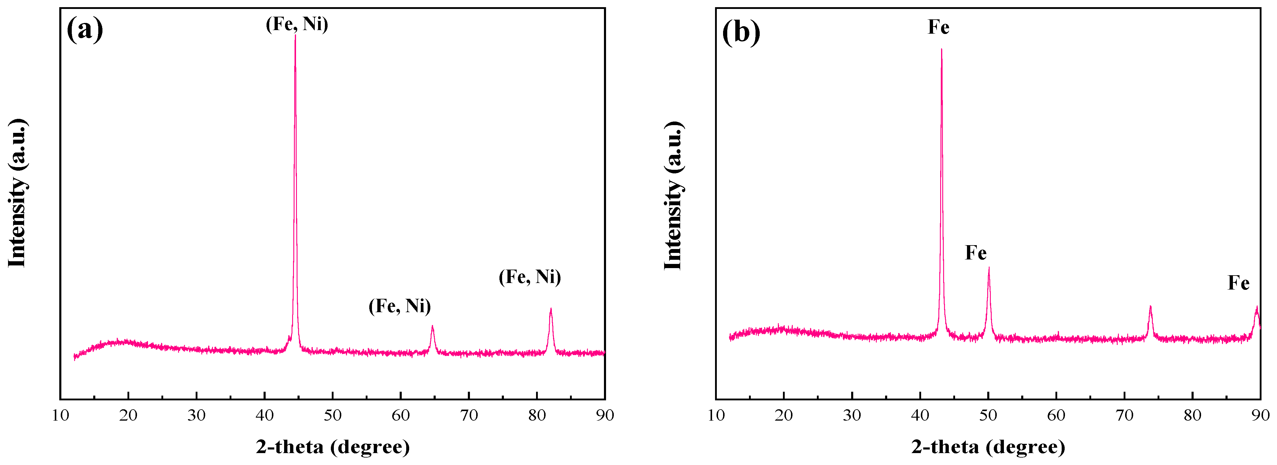
4.1. Microstructure
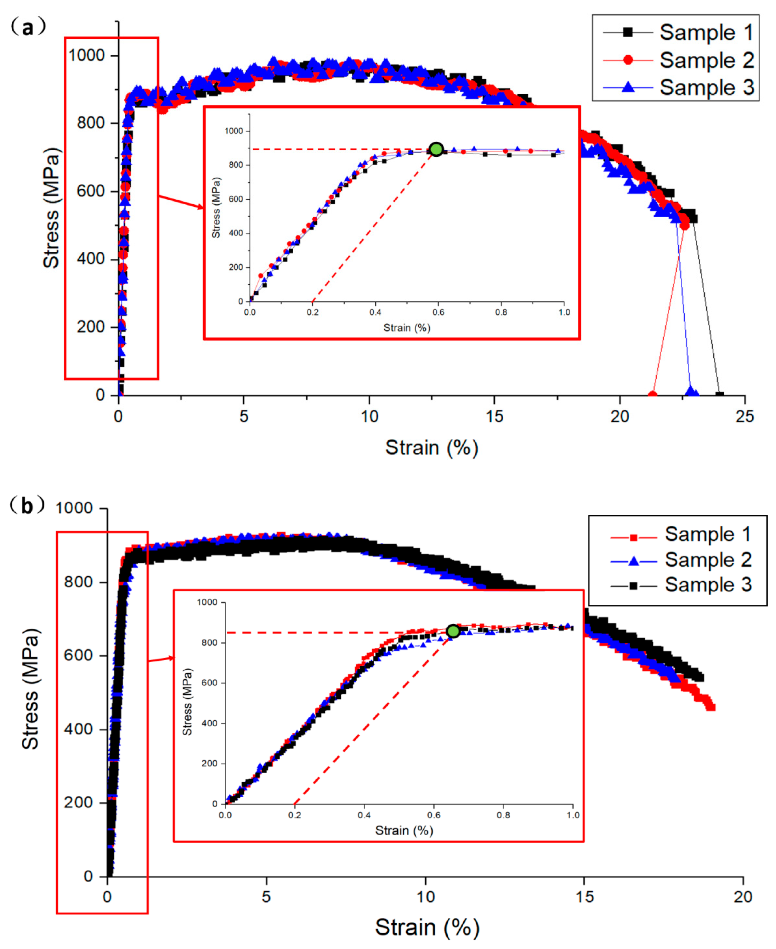
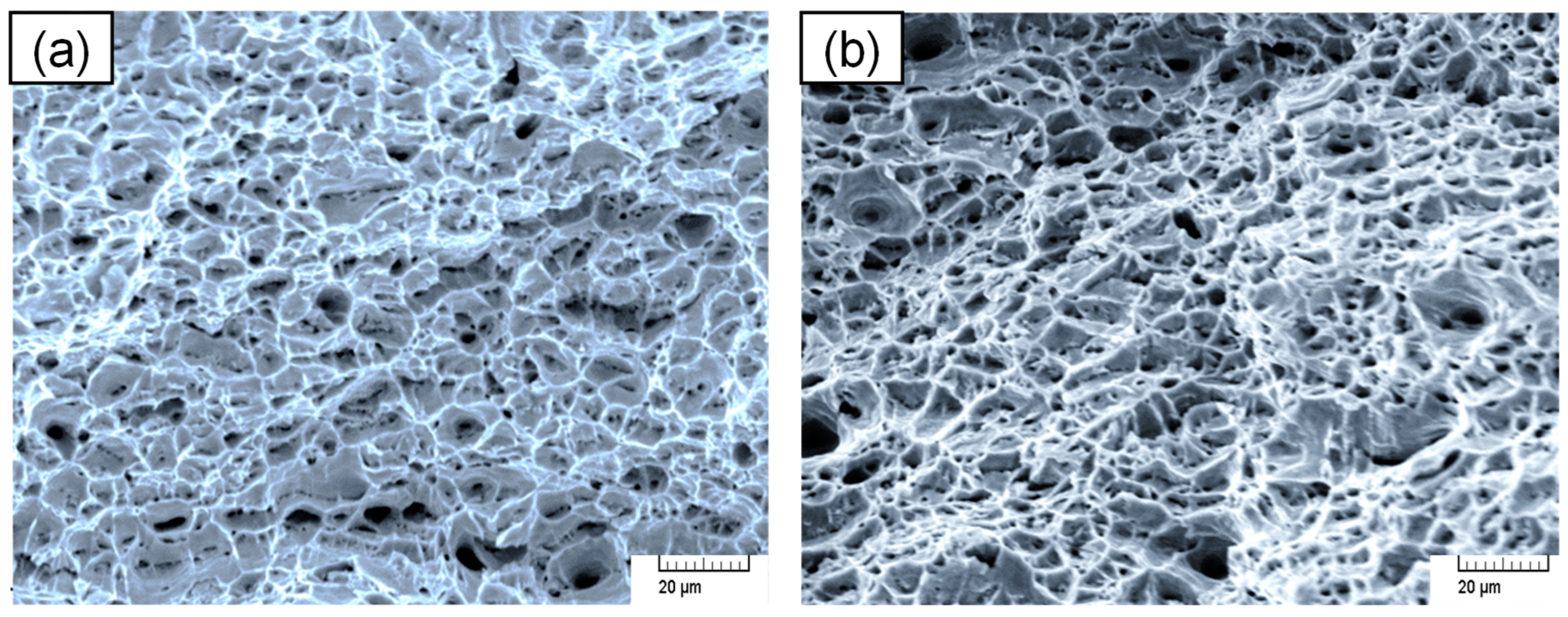
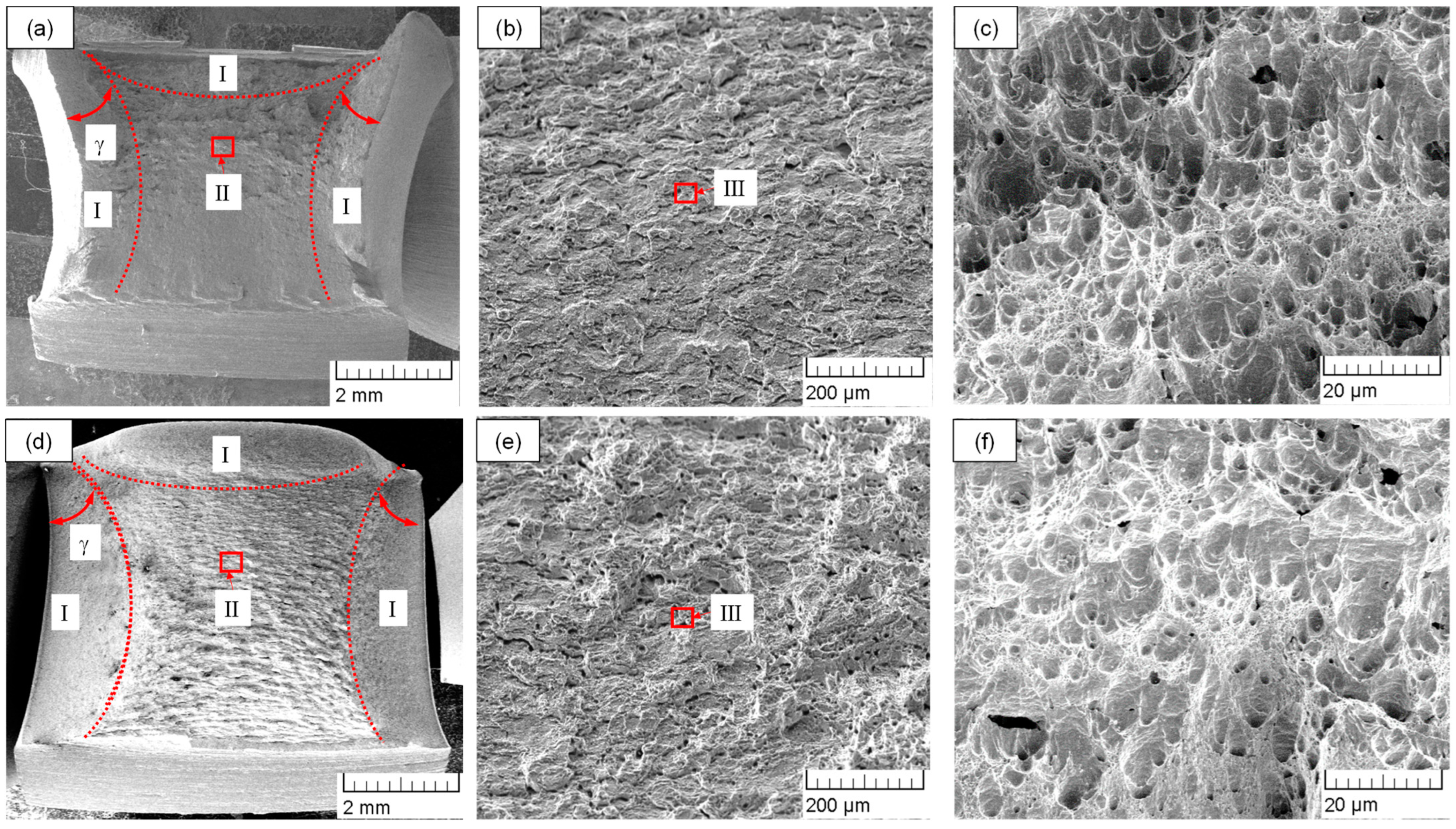
4.2. Tensile and Impact Mechanical Properties
5. Cause Analysis of Wellhead Leakage
5.1. FE Modeling
5.2. Analysis of Thread Contact Pressure
5.3. Discussion
6. Conclusions and Discussion
- (1)
- Through a series of material tests, it can be seen that the microstructure and mechanical properties of casing materials and hanger materials could meet the field requirements.
- (2)
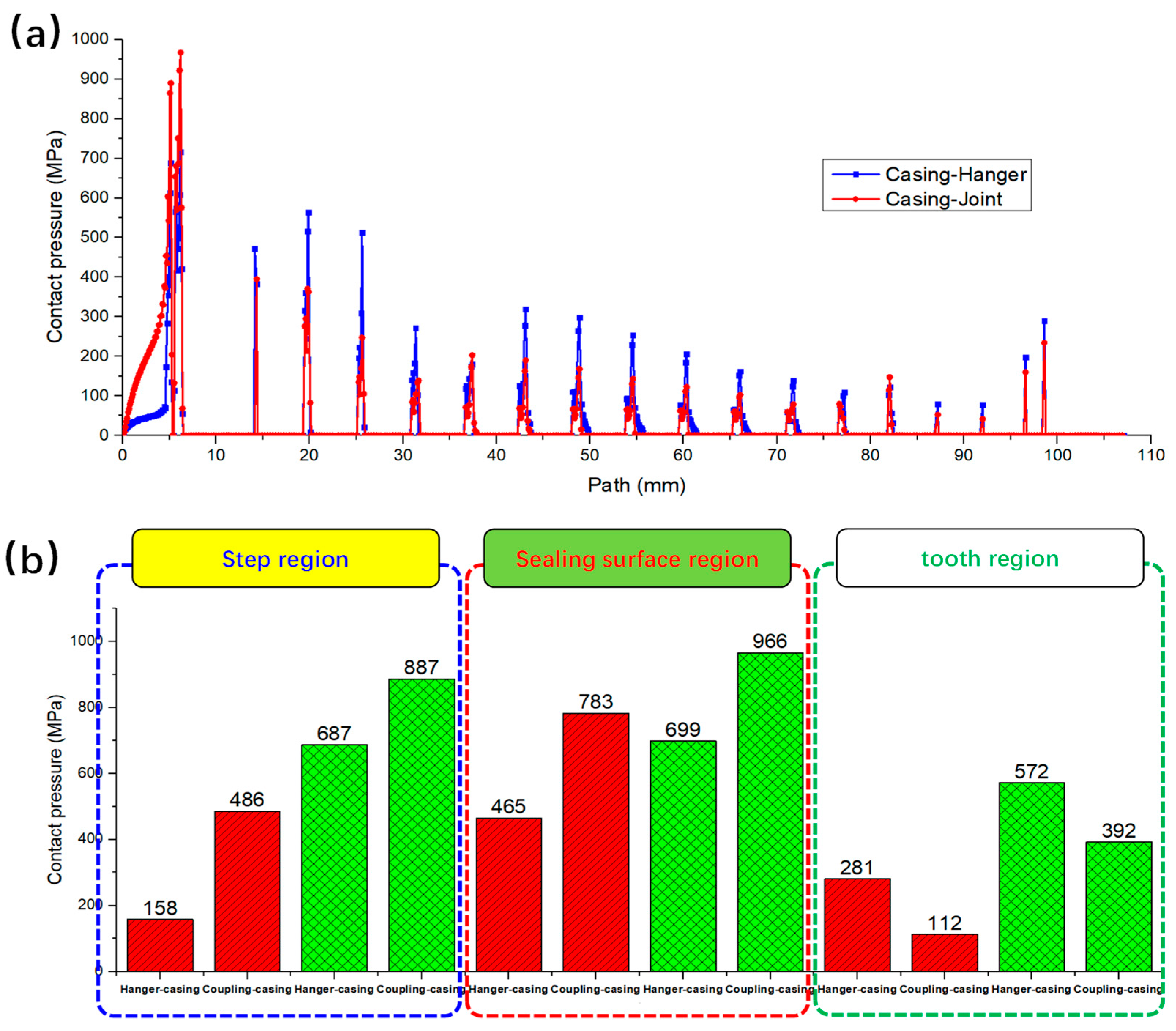
- The connection degree of the hanger–casing is insufficient at the torque recommended by the manufacturer according to the connection degree of the coupling–casing. The contact pressure on the tooth region is significantly higher, which results in a greater sum of torque shared in the thread teeth region in the hanger–casing system; at the same torque, the contact degree in the sealing surface and the step is relatively insufficient.
- (3)
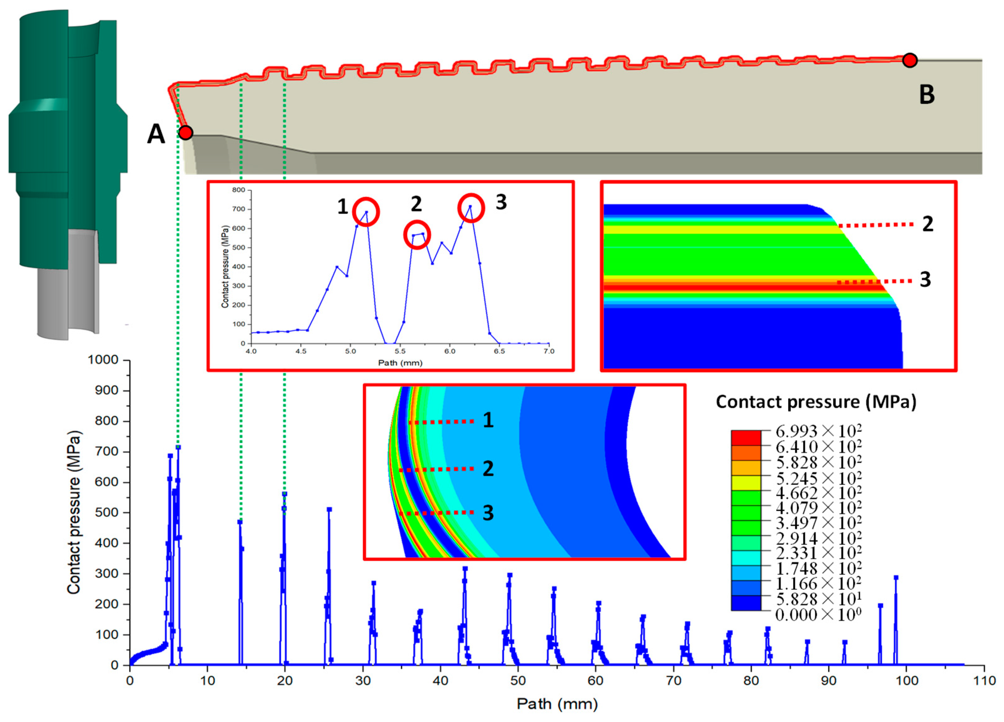
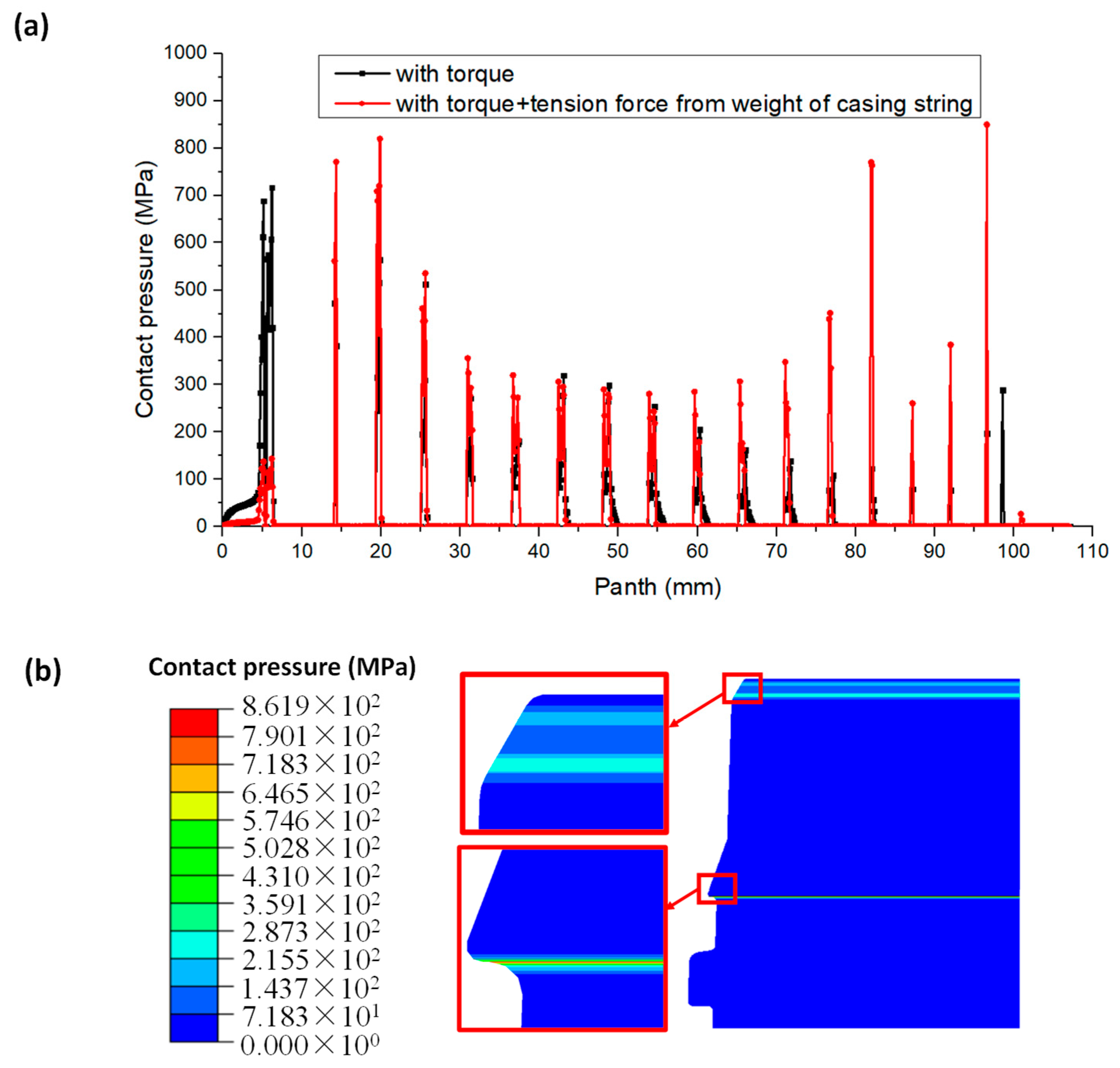
- Neither the hanger nor casing has plastic deformation according to the tensile test results of the two materials (UNS N07718 and P110), and the maximum sealing contact force between A and B should be distributed on the sealing surface; this stress distribution is consistent with the initial design of the thread structure.
- (4)
- The closer the teeth are to the middle, the lower the contact pressure on each thread tooth; the sealing pressure range of each thread bearing surface is 15~392 MPa. It can be seen that the high contact pressure ring of zone 2 on the sealing surface plays an effective sealing role under the manufacturer’s recommended torque (20,465 N·m).
- (5)
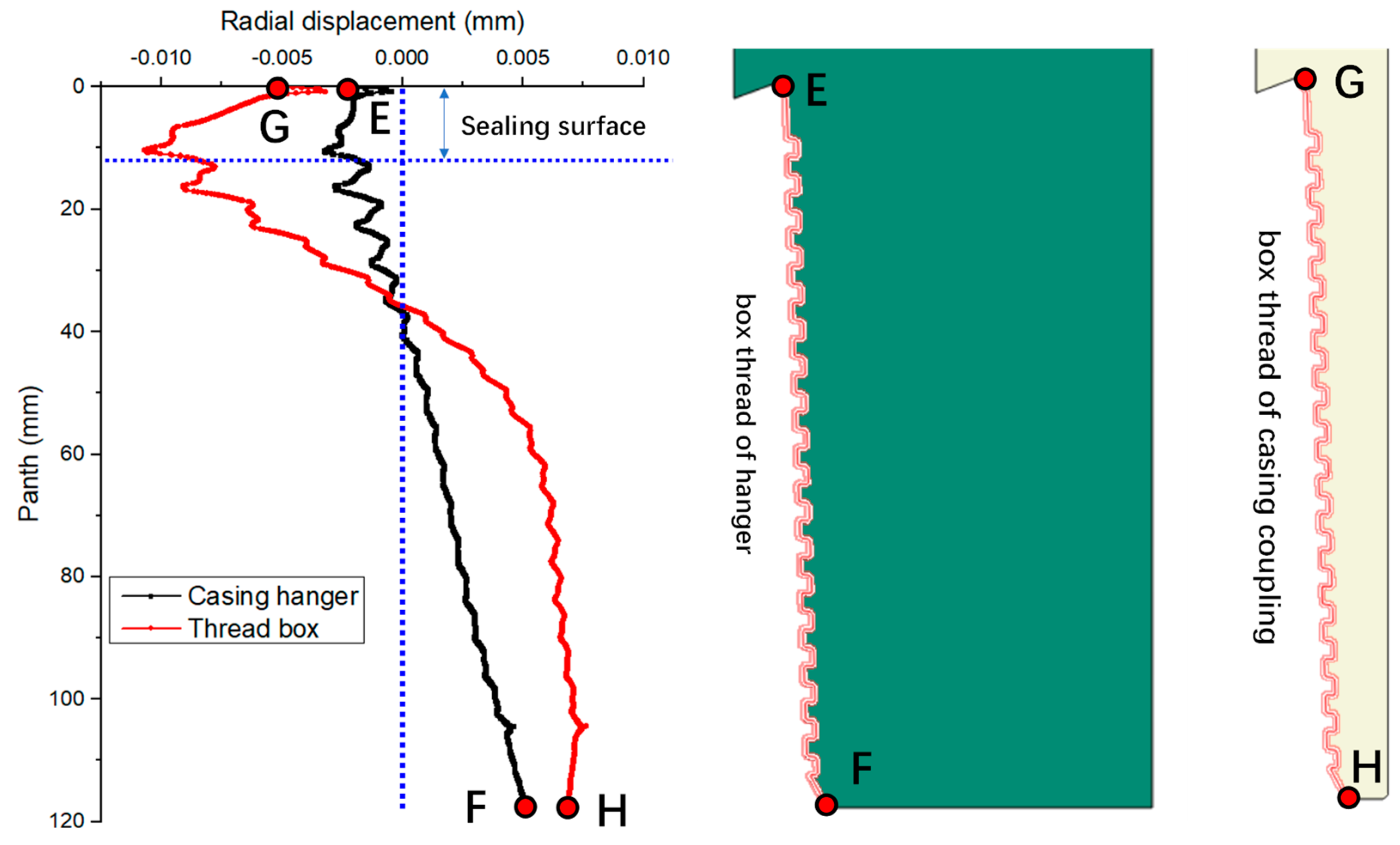
- Under the same torque, due to the large wall thickness of the hanger box thread (average wall thickness is 40 mm, average wall thickness of casing coupling box thread is 14 mm), a small radial deformation can cause a large contact pressure in the tooth area, and a large contact pressure causes a large accumulation of torque in the tooth area.
- (6)
- The maximum contact pressure between the pin and box thread of the hanger can fully meet the internal pressure test requirements when the torque is increased by 25%.
Author Contributions
Funding
Data Availability Statement
Conflicts of Interest
Abbreviations
| A2 | contact area of the N2 node | mm2 |
| R2 | distance from the N2 node to the central axis of casing | mm |
| L1~L5 | lengths marked in Figure 9 | mm |
| P2 | contact pressure in N2 node | MPa |
| F2 | contact force in N2 node | N |
| T2 | torque in the control area of N2 node | N·mm |
| Ri | distance from the Ni node to the central axis of casing | mm |
| Li | length of influence range of the Ni node | mm |
| Pi | contact pressure in Ni node | MPa |
| Ti | torque in the control area of Ni node | N·mm |
| ff | friction coefficient between pin thread and box thread | / |
| LT | length of A-B path | mm |
| TT | total torque, which is the integral of the torques of all nodes on the A-B path | N·m |
References
- Liu, Y.; Lian, Z. Failure analysis on rubber sealing structure of mandrel hanger and improvement in extreme environments. Eng. Fail. Anal. 2021, 125, 105433. [Google Scholar] [CrossRef]
- Liu, Y.; Lian, Z.; Deng, C.; Zhang, Q.; Mu, Y. Design and experimental study on full-metal sealing structure of mandrel-type casing hanger. Adv. Mech. Eng. 2019, 11, 1–16. [Google Scholar] [CrossRef]
- Ferjani, M.; Averbuch, D.; Constantinescu, A. A computational approach for the fatigue design of threaded connections. Int. J. Fatigue 2011, 33, 610–623. [Google Scholar] [CrossRef]
- Shahani, A.R.; Sharifi, S.M.H. Contact stress analysis and calculation of stress concentration factors at the tool joint of a drill pipe. Mater. Des. 2009, 30, 3615–3621. [Google Scholar] [CrossRef]
- Xu, Z.; An, C.; Xie, Z.; Zhang, J.; Lim, F.; Zhang, Y. Full-scale resonant bending fatigue testing of casing joints under bending moment load. Int. J. Press. Vessel. Pip. 2024, 207, 105105. [Google Scholar] [CrossRef]
- Chen, Y.; Liu, X.; Yi, H.; He, C.; Xiao, G.; Tan, J.; Su, A. Parameter optimization of rubber cylinder of expansion liner hanger based on numerical simulation. J. Eng. Appl. Sci. 2022, 69, 32. [Google Scholar] [CrossRef]
- Oku, Y.; Sugino, M.; Ando, Y.; Makino, T.; Komoda, R.; Takazaki, D.; Kubota, M. Fretting fatigue on thread root of premium threaded connections. Tribol. Int. 2017, 108, 111–120. [Google Scholar] [CrossRef]
- Liu, Y.; Lian, Z.; Zou, J.; Deng, C.; He, Y. Fracture failure analysis and research on thread joint of drive shaft shell of positive displacement motor. Eng. Fail. Anal. 2020, 118, 104805. [Google Scholar] [CrossRef]
- Santus, C.; Bertini, L.; Burchianti, A.; Inoue, T.; Sakurai, N. Fatigue resonant tests on drill collar rotary shouldered connections and critical thread root identification. Eng. Fail. Anal. 2018, 89, 138–149. [Google Scholar] [CrossRef]
- Di, Q.; Qin, K.; Chen, T.; Liu, B.; Li, S.; Wang, W.; Zhang, H. An innovative method for studying the dynamic failure mechanism of box connection of stabilizer in large diameter wellbore of ultra-deep wells. Eng. Fail. Anal. 2020, 118, 104805. [Google Scholar] [CrossRef]
- Zhuang, Y.; Gao, L.X.; Yuan, P.B. Force analysis and tightening optimization of gas sealing drill, pipe joints. Eng. Fail. Anal. 2015, 58, 173–183. [Google Scholar]
- Chen, F.; Di, Q.; Li, N.; Wang, C.; Wang, W.; Wang, M. Determination of operating load limits for rotary shouldered connections with three-dimensional finite element analysis. J. Pet. Sci. Eng. 2015, 133, 622–632. [Google Scholar] [CrossRef]
- Shokry, A.; Elgibaly, A. Well design optimization through the elimination of intermediate casing string. J. King Saud Univ.-Eng. Sci. 2022, 34, 571–581. [Google Scholar] [CrossRef]
- Howard, J.A.; Grant, L.; D’Amico, R.; McSpadden, A.R.; Kalil, I.A.; Trevisan, R.; Glover, S. Casing Design Load Case for Shut-In after Worst Case Discharge Using a Progressive Depth Analysis Approach; Society of Petroleum Engineers: Richardson, TX, USA, 2023; SPE-215126-MS. [Google Scholar]
- Wang, Y.; Chen, G.; Yang, H.; Jing, J. A special thread design for failure prevention of expandable casing. Alex. Eng. J. 2021, 60, 213–225. [Google Scholar] [CrossRef]
- Yuan, G.J.; Yao, Z.Q.; Han, J.Z. Experimental Research on Stress Field Distribution of Oil Tubing Thread Connection during Make and Break Process. Eng. Fail. Anal. 2004, 11, 537–545. [Google Scholar] [CrossRef]
- Zhu, X.; Dong, L.; Tong, H. Failure analysis and solution studies on drill pipe thread gluing at the exit side of horizontal directional drilling. Eng. Fail. Anal. 2013, 33, 251–264. [Google Scholar] [CrossRef]
- Xiong, M.; Xie, J.; Liu, H.; Zhang, J.; Liu, W.; Hu, K.; Hu, F. Development and Application of 140 MPa Mandrel Casing Head in Ultra-High Pressure Gas Well. In Proceedings of the International Petroleum Technology Conference, IPTC-21362-MS, Kuala Lumpur, Malaysia, 23 March–2 April 2021. [Google Scholar]
- Sathuvalli, U.B.R.; Suryanarayana, P.S.; Bathgate, G.; Delgado, J.; Arcos, R.; Painter, J.; Rahman, S. Multi-String Analysis of a Mudline Hanger System in High Temperature Wells During Production. In Proceedings of the Offshore Technology Conference, OTC-32487-MS, Houston, TX, USA, 1–4 May 2023. [Google Scholar]
- Yeow, M.L.; Khaidzir, K.A.M.; Abu-Jafar, F.; Ismail, H.; Kasim, H. Wellhead and Casing Hanger with Hydraulic Features to Run and Operate Downhole Casing Isolation Valve; Design and Experiences Based on Actual Installation Successes. In Proceedings of the Offshore Technology Conference, OTC-34931-MS, Houston, TX, USA, 9 May 2024. [Google Scholar]
- Zhang, Z.; Sang, P.; Sang, Z.; Duo, H.; Lv, Y.; Zheng, Y.; Zhang, C. Analyzing failure of casing head slip hanger. Eng. Fail. Anal. 2020, 108, 104301. [Google Scholar] [CrossRef]
- Liu, Y.; Lian, Z.; Shi, T.; Sang, P. Fracture failure analysis and research on slip of casing head. Eng. Fail. Anal. 2019, 97, 589–604. [Google Scholar] [CrossRef]
- Liu, Y.; Qian, L.; Xia, C.; Yi, X. Design and experimental study on a novel sealing structure of rotary control head for coalbed methane underbalanced drilling. Eng. Fail. Anal. 2022, 139, 106441. [Google Scholar] [CrossRef]
- Chen, Y.; Tan, J.; Xiao, G. Investigation on the Depth of Slip Hanger Teeth Bite into Casing and the Mechanical Properties of Casing under Different Suspension Loads in Ultra-Deep Wells. Stroj. Vestn.-J. Mech. Eng. 2021, 67, 516–524. [Google Scholar] [CrossRef]


| Type | Depth (m) | Outer Diameter (mm) | Thickness (mm) | Steel Grade | Thread Type |
|---|---|---|---|---|---|
| Surface casing | 0~399 | 339.7 | 9.65 | J55 | BC |
| Intermediate casing | 0~3148 | 244.5 | 11.99 | P110 | BC |
| Production casing | 0~6218 | 139.7 | 12.7 | P110 | BX2 |
| Property | Casing Hanger | P110 Casing |
|---|---|---|
| Average ± Standard Deviation (n = 3) | Average ± Standard Deviation (n = 3) | |
| Yield strength σy, Rp 0.2 (MPa) | 889.62 ± 8.67 | 826.21 ± 7.73 |
| Tensile strength σu, (MPa) | 980.27 ± 7.23 | 913.41 ± 7.71 |
| Yield ratio σy/σu | 0.91 ± 0.01 | 0.90 ± 0.01 |
| Young’s modulus E (GPa) | 216 ± 0.001 | 204 ± 0.001 |
| Elongation δ (%) | 22.47 ± 0.62 | 19.12 ± 1.12 |
| Property | Casing Hanger | P110 Casing |
|---|---|---|
| Average ± Standard Deviation (n = 3) | Average ± Standard Deviation (n = 3) | |
| Impact energy (J) | 150.43 ± 1.62 | 154.36 ± 1.56 |
| Crack initiation energy (J) | 42.62 ± 0.15 | 45.91± 0.22 |
| Crack propagation energy (J) | 107.81 ± 0.16 | 108.45 ± 0.82 |
Disclaimer/Publisher’s Note: The statements, opinions and data contained in all publications are solely those of the individual author(s) and contributor(s) and not of MDPI and/or the editor(s). MDPI and/or the editor(s) disclaim responsibility for any injury to people or property resulting from any ideas, methods, instructions or products referred to in the content. |
© 2024 by the authors. Licensee MDPI, Basel, Switzerland. This article is an open access article distributed under the terms and conditions of the Creative Commons Attribution (CC BY) license (https://creativecommons.org/licenses/by/4.0/).
Share and Cite
Mou, Y.; Xie, Y.; Wei, F.; Zhao, H.; Han, L. Research on Thread Seal Failure Mechanism of Casing Hanger in Shale Gas Wells and Prevention Measures. Processes 2024, 12, 1253. https://doi.org/10.3390/pr12061253
Mou Y, Xie Y, Wei F, Zhao H, Han L. Research on Thread Seal Failure Mechanism of Casing Hanger in Shale Gas Wells and Prevention Measures. Processes. 2024; 12(6):1253. https://doi.org/10.3390/pr12061253
Chicago/Turabian StyleMou, Yisheng, Yonggang Xie, Fengqi Wei, Han Zhao, and Lihong Han. 2024. "Research on Thread Seal Failure Mechanism of Casing Hanger in Shale Gas Wells and Prevention Measures" Processes 12, no. 6: 1253. https://doi.org/10.3390/pr12061253