Article

Design and Analysis of Small Fallen Leaf Collection, Crushing, and Recycling Vehicle

School of Mechanical and Automotive Engineering, Liaocheng University, Liaocheng 252000, China
*
Author to whom correspondence should be addressed.
Processes 2024, 12(9), 2011; https://doi.org/10.3390/pr12092011
Submission received: 20 July 2024 / Revised: 17 September 2024 / Accepted: 17 September 2024 / Published: 19 September 2024
(This article belongs to the Section Advanced Digital and Other Processes)

Abstract

:
Leaf recycling, a crucial component of urban environmental protection, aims to systematically collect and reuse fallen leaves on streets. At present, fallen leaves are usually cleaned manually by sanitation workers, and environmental protection departments then use special cars to transport fallen leaves to treatment stations for incineration. This not only requires a significant amount of labor and material resources but also causes air pollution and wastes fallen leaves. In this study, a collecting, crushing, and recycling vehicle was designed to solve this problem. The proposed device significantly improves the efficiency of collecting fallen leaves and facilitates their secondary utilization. The design process is described in detail, including the working design of the entire device, static analysis, and transmission system design. The entire vehicle model was 3D printed to verify that the initial design concept satisfies the assembly and production requirements of the device.

1. Introduction

In the cold autumn and winter seasons, a large number of fallen leaves not only seriously affect the appearance and conditions of roads but also increase cleaning workloads. Most areas still rely on cleaning workers to sweep and collect fallen leaves manually, and environmental protection departments then use special cars to transport fallen leaves to a treatment station, where they are burned as ordinary garbage [1]. Traditional leaf collection and treatment methods not only consume a large amount of human and material resources but also pollute the environment during the process of burning the leaves [2]. Because of the fluffy characteristics of leaves, the volume of the same weight is three to five times that of ordinary garbage; thus, the transportation cost is relatively high, and the value of the leaves as fertilizer is wasted. With the rapid development of robotics, material technology, automation technology, and artificial intelligence, many intelligent machines have been designed. To improve the speed of leaf cleaning and reduce labor requirements, many researchers have proposed various structural patterns for leaf-cleaning equipment.
Grishko et al. proposed a new road cleaning method using the joint operation of a watering truck and sweeper. This not only solves the problem of secondary dust caused by ordinary road sweepers but also improves the cleaning of flaky and flocculent dust [3]. Hamzeh et al. adopted a discrete-element model, analyzed the interaction between the disk brush and the road surface during operation, and reached the following conclusion. With an increase in the rotational speed of the disk brush, the friction coefficient between the disk brush and the road surface decreases, and the grounding pressure of the disk brush also decreases; thus, the driving torque of the disk brush decreases accordingly [4,5]. Li et al. designed a new leaf sweeper based on UG NX11.0 software. It mainly consists of a sweeping roller brush, intermittent shovel, windmill-like rake, conveyor belt, collection box, and driving motor. Thise design is easy to operate, energy-saving and environmentally friendly and it reduces the labor force required to some extent [6]. Lv et al. designed an integrated machine for collecting and pressing fallen leaves that is characterized by the direct absorption of fallen leaves into the compression box by a fan, followed by molding and compression to make high-density blocks for convenient storage and transportation [7]. Nakagawa et al. developed an autonomous leaf-sweeping and leaf-collecting blower robot. It uses three active casters as the moving mechanism, and the driving and steering shafts of each wheel are driven by motors, realizing movement in all directions. The blower is fixed to the robot in a slightly downward-sloping manner. Nakagawa evaluated the influences of different moving speeds of robots on the leaf-cleaning effect and found that the cleaning effect was best when the moving speed of the robots was 0.4 m/s [8]. Zhong et al. studied a new type of leaf-sweeping equipment integrating leaf sweeping, compression, and conveyance and used SOLIDWORKS 2022 and other software to draw, model, and simulate the main parts, solving coordination problems relating to mechanism motion [9]. Lee et al. developed a leaf-sweeping robot. The hardware of the robot is composed of a blower, an air duct, and a cleaning mechanism, and the controller of the robot is composed of an Arduino MEGA 2560 and an ESP-12E wireless module. Through variance analysis, it was determined that the best working wind speed of the blower is approximately 2.85 m/s. The noise level of the robot is 17 dB lower than that of a traditional leaf blower [10].
In addition to performing structural design, many researchers have developed automatic path planning for leaf sweepers, visually self-reconfigurable sweeping robots, and deep-learning models in the field of visual recognition. Delle Donne et al. developed a leaf-sweeping task route in Trenque Lauquen, Argentina, based on an integer linear programming model. Based on this method, the number of sweepers can be determined accurately, and the workload of each sweeper can be balanced, improving the efficiency of leaf sweeping and reducing the fuel consumption of the sweepers [11]. Yi et al. designed a road-cleaning robot, “Panthera”, based on visual self-reconstruction. The segmented road surface of a masked deep convolutional neural network (CNN) was used as the input for the closed-loop feedback control method so that the robot could accurately adjust the requirement of changing the width during movement [12]. Hsia et al. studied an intelligent leaf-blowing robot based on a deep-learning model. Based on the CNN concept, computer vision was used to identify whether leaves had fallen on the ground. A ResNet50 deep CNN was used as the training model to identify leaves of different colors and shapes. The embedded system was used to sense the blade data to determine the movement of the machine based on control algorithms. An accelerator-based CNN model was implemented in an embedded system, and the recognition speed reached 20 frames per second. Automatic leaf blowers can replace human labor [13]. Li et al. used an STC12C5A60S2 single-chip microcomputer as the core, infrared sensor technology, and motor control technology to enable intelligent robots to clean fallen leaves in road areas. The intelligent cleaning robot had an infrared module, walking drive module, power module, positioning module, etc., which could automatically identify and clean fallen leaves on a road [14].
The key parts of the vehicle can be manufactured via 3D printing. Sheng et al. introduced a novel nonlinear gradient TPMS structural design method, regulating the porosity of the TPMS structure through trigonometric functions, and designed Gyroid sin and Gyroid sin square structures [15]. Guo et al. proposed a damage-resistant ceramic process involving internal and external strengthening and toughening to enhance the ceramic’s ability to resist fracture [16]. Kong et al. proposed and developed a four-dimensional (4D-printing) method based on vat photopolymerization (VPP) to solve the problem that the manufacturing of polymer-derived ceramics is too dependent on complex control systems [17]. Wu et al. used vat photopolymerization (VPP) technology to 3D print a pearl layered bionic ceramic scaffold, filled with polymer, and reinforced with carbon fiber to create a high-strength and high-toughness carbon fiber-reinforced bionic composite [18].
Based on the above research, in this study, the practical requirements for leaf cleaning and recycling were examined. However, most previous leaf-cleaning systems are characterized by simple structures and single functions. While it is undeniable that some advanced leaf treatment facilities have been developed, they often feature complex structures and high costs and lack the functionality required for direct leaf recycling. The small fallen leaf collection, crushing, and recycling vehicle proposed can not only clean and collect fallen leaves but also pulverize and recycle fallen leaves to make usable biofertilizers.
This article is organized as follows. In Section 2, the main design features of small fallen leaf collection, crushing, and recycling vehicles are described according to the requirements briefly outlined above. In Section 3, the manufacturing process of the machine is introduced, and the verification of the strength and stiffness of the main components by static analysis is described. The design of the transmission system of the machine is discussed in Section 4. In Section 5, the 3D printing process is described, and it is verified that the initial design concept meets the assembly and production requirements of the device. Section 6 presents some conclusions and a discussion of planned future work.

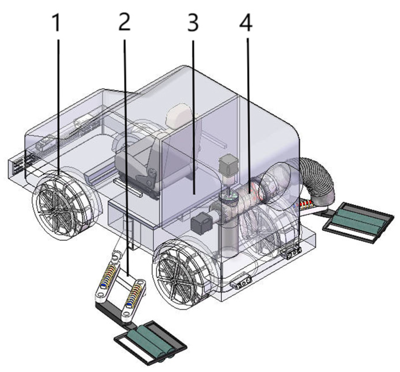
2. Fallen Leaf Recycling Vehicle Design

The size of the small fallen leaf collection and crushing recovery vehicle should be suitable for road-level environments and complex environments, such as those involving trees and bushes. Therefore, the size of the small fallen leaf collection, crushing, and recycling vehicle must be based on actual environmental data and refer to the principles and methods of China’s engineering technology and related disciplines in environmental engineering. The small vehicles in this article mainly work in parks, on campus, and on urban or suburban roads. The model simulates the operation of the actual equipment, and all parameters of the model are proportionately restored. Based on the structural and dynamic parameters of special-operation vehicles, such as road garbage sweepers, medium sprinklers, and small harvesters, the main technical parameters of the small fallen leaf collection, crushing, and recycling vehicle were obtained, as shown in Table 1.
For this small fallen leaf collection, crushing, and recycling vehicle, the safety factor is not a fixed value because it involves the design of the vehicle, the environment of use and the operating conditions. According to the general engineering practice, the safety factor is usually between 1.5 and 3; in this paper, 3 is taken.
The small fallen leaf collection, crushing, and recycling vehicle is mainly composed of hob wheels, a retractable collection brush, absorption, crushing, and recycling mechanisms, a dynamic coupling system, and a cab. The overall structure of the system is shown in Figure 1.
The main functions of the small fallen leaf collection, crushing, and recycling vehicle can be divided into the following four points.
(1) The fallen leaf treatment process must be stable to ensure efficient cleaning. In this process, the environment and terrain are more complex, and the vehicle must be equipped with a wheel that can adapt to a variety of terrains according to the terrain reconstruction. The wheel diameter, wheel shape, and telescopic wheel hob must adapt to a variety of complex terrains to improve working efficiency and expand the scope of work.
(2) To increase the working range of the device, a side brush is employed. The lifting of the side brush is controlled by the hydraulic system. The roller brush is fixed on one side of the parallelogram using the parallelogram mechanism expansion principle in the extension part of the side brush, and the collection distance of the roller is controlled by expansion.
(3) To realize the highly efficient use of the decomposed leaves, a design scheme was devised to collect, decompose, and reuse fallen leaves. The pressure difference is created by rotating the fan, wherein the fallen leaves are sucked into the device, and a spiral reamer is used to control the cutting tool by controlling the spiral coefficient to ensure that the mean diameter of the decomposed leaves is within 2 mm.
(4) The transmission part and a new dynamic coupling system were designed with 12 kinds of gear operation without a power interrupt transmission device. They are used for the transmission operation of the entire vehicle, cooperating with the vehicle to adapt to a variety of road surfaces and improve the ride comfort of the vehicle.

3. Structural Design and Analysis of Small Leaf Litter Collection, Crushing and Recycling Vehicle

The small fallen leaf collection and crushing recovery vehicle is mainly composed of retractable hob wheels, a retractable collection brush, and a litter collection and recovery device.

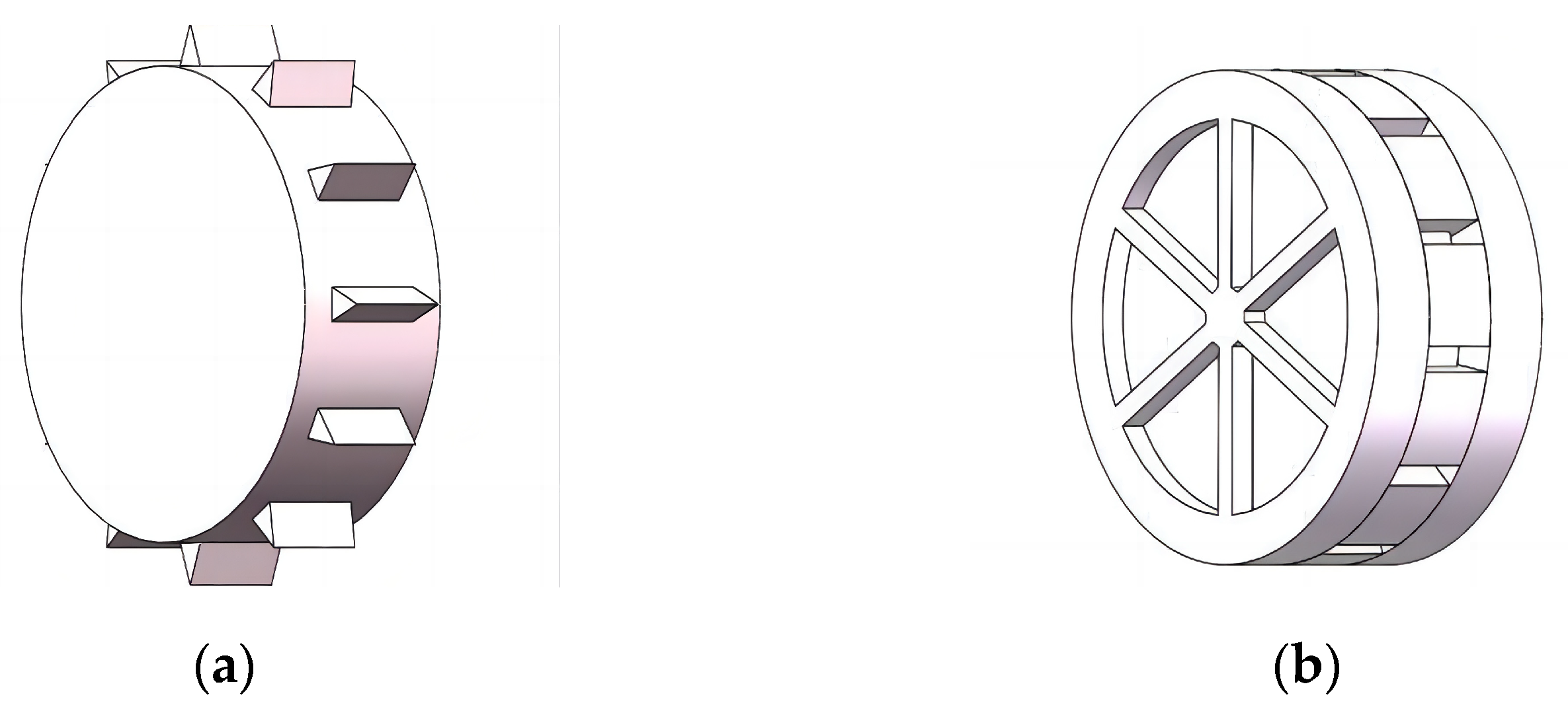
3.1. Retractable Hob Wheel

3.1.1. Design of Retractable Hob Wheel

As shown in Figure 2, the retractable hob wheel based on iris structure gear transmission control comprises a wheel body, an iris structure gear transmission train, and a control device. The iris structure is arranged inside the wheel body, and the retractable adjustment of the gear drive train of the iris structure is realized using a control device to drive the extension and contraction of a retractable hob with teeth. The expansion and contraction of the hob can absorb the shock and impact forces caused by uneven road surfaces and improve the stability and safety of the vehicle. The control device adopts a gear transmission mode that can realize accurate retractable adjustments and improve the reliability and stability of the wheel.
The retractable hob wheel based on iris structure gear drive control includes the wheel body, iris structure gear drive train, and control device. The outer wheel hub is nested inside the inner iris hub, the inner iris hub is cut into the gear ring, and the inner iris hub is cast in the groove for pinion installation. The position of the gear shaft is just full, the pinion is installed on the gear shaft, and the gear ring is exactly matched. Twelve openings are made on the periphery of the wheel hub in the iris to place the hob, two internal grooves are made on the periphery of the wheel hub in the iris to place the motor, and the motor pinion is covered on the motor. The thickness of the pinion is the sum of the thicknesses of one side of the gear ring and the hob to ensure that the gear transmission does not jam. The two ends of the gear ring extend the outer gear, and the motor pinion is engaged inside. The meshing range of the extended outer gear and motor pinion meets the expansion range of the tip of the hob.
The specific working mode includes the following: (1) wheel body, iris structure gear transmission system, and control device and (2) the motor rotation in the iris hub, which drives the motor pinion to rotate, thereby driving the motor pinion and outer gear ring of the tooth ring to engage and rotate. The gear ring drives the pinion to rotate, thereby driving the hob expansion, and the outer hub helps protect the internal structure.

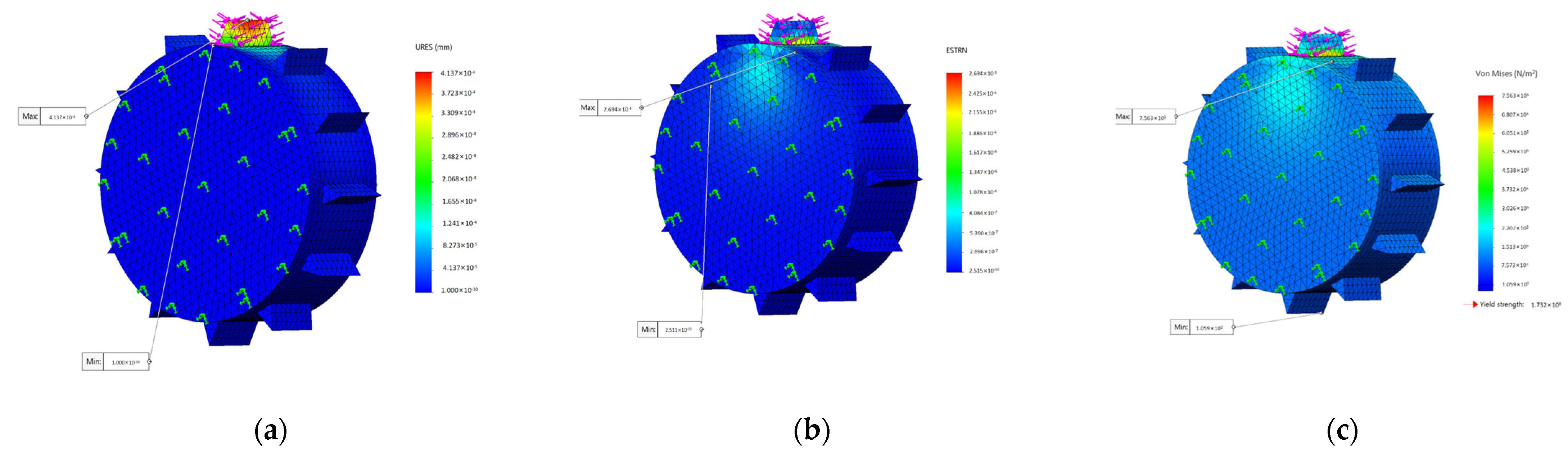
3.1.2. Static Analysis of Wheel

On an uneven road surface, the gear drives the hob to expand, and the hob is fixed when all are extended out, which is equivalent to the wheel outside the wheel hub inside being solid, so the simplified model is a simple model of a solid cylinder with 12 fixed extension distances of the hob and provides the same material strength. When the road is smooth, the gear does not drive the hob to expand. Therefore, in the simplified model, the gear hob part is removed, which is equivalent to only the internal and external hub compositions and provides the same material strength. A simplified diagram of the wheel model is shown in Figure 3.
During work, the quality of the fallen leaves is ignored. Referring to the actual weights of existing garbage recycling vehicles, litter collection vehicles, litter crushing vehicles, and other engineering vehicles, it is stipulated that the total mass of the machine is 13,200 kg. Excluding the mass of the four wheels, the mass of the machine is 7388 kg. Assuming that g = 9.8 m/s2, the calculated force received by each wheel is 18,470 N. The material properties are listed in Table 2.
The overall force of the vehicle was analyzed, and the overall weight was evenly distributed to the four wheels. Considering that the hob is distributed around the wheel hub, and only one blade of the hob on the four wheels touches the ground at each moment during the driving process, the four hobs support the weight of the entire car at each moment. Therefore, the wheel model can be simplified into a monolithic structure, in which each wheel is subjected to the same forces. The boundary conditions of the wheel are set at the joint between the wheel and the axle for the fixed support. The SOLIDWORKS simulation module was used to perform a static analysis of the above situation for the wheel, in which a stainless-steel (ferritic) material was selected for the working device, and a von Mises diagram was obtained, as shown in Figure 4.
The displacement variation range is 2.515 × 10⁻¹⁰ to 2.694 × 10⁻⁶ mm, which is in accord with the variation range. The strain range is 1.000 × 10⁻³⁰ to 4.137 × 10⁻⁴ mm, which is in line with the material strain variation range. The range of the stress variation also agrees with the maximum yield force limit. Therefore, when 12 hobs are evenly distributed around the edges, the working requirements are met, and the wheel strength meets the requirements.

3.2. Retractable Collection Brush

3.2.1. Design of Retractable Collection Brush

As shown in Figure 5, the retractable brush collecting device comprises a roller brush, a connecting rod mechanism, and a power device. The power device is composed of a motor, a hydraulic cylinder, and an electrified solenoid. The collecting brush is connected to the bottom plate of the car and distributed symmetrically. Through an adjustable parallelogram linkage mechanism, the cleaning area can be increased, and the cleaning effect can be improved.
The hydraulic cylinder is installed behind the car chassis, and, when the brush is used, the brush is moved down; when the brush is not used, the brush is moved up and put away. The two telescopic brushes are symmetrically arranged, and the hydraulic cylinder is linked with a support plate for the motor to drive the hydraulic rotating shaft to rotate to turn out of the car body when the brush is used, and to turn into the car body when the brush is not in use. The hydraulic rotating shaft is a combination of a rotating shaft and a hydraulic cylinder, and the hydraulic cylinder is linked to the hydraulic rotating shaft to push the telescopic brush forward to move close to the vacuum cleaner mouth.

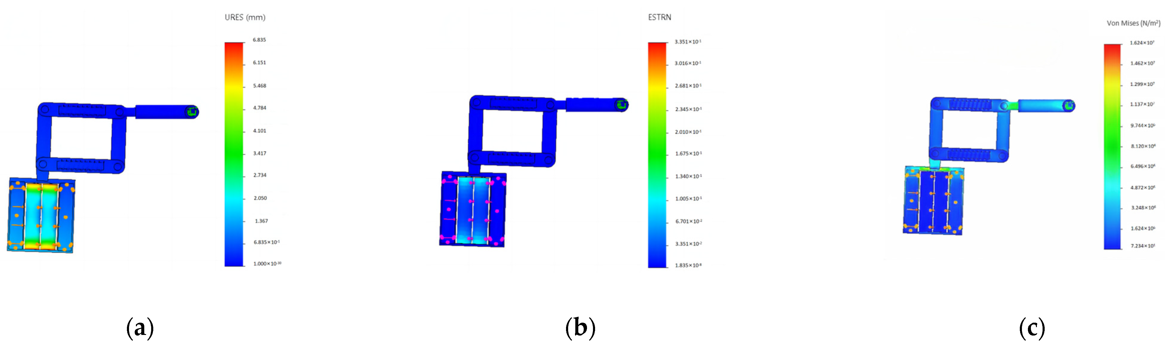
3.2.2. Static Analysis of Retractable Collection Brush

Finite-element analysis of the side brush is complicated, involving engineering mechanics and numerical calculation methods. The performance of the side brush directly affects the working efficiency and service life of the equipment. Finite-element analysis of the side brush can predict its stress, strain, and deformation under different working conditions to optimize its design and improve its performance. Before the finite-element analysis begins, the material, mass, volume, and density of each component should be specified, as shown in Table 3.
Stress and strain displacement nephograms were derived using finite-element analysis. As shown in Figure 6, the maximum stress on the working device is less than the yield force, and the device structure meets the requirements for different working conditions.

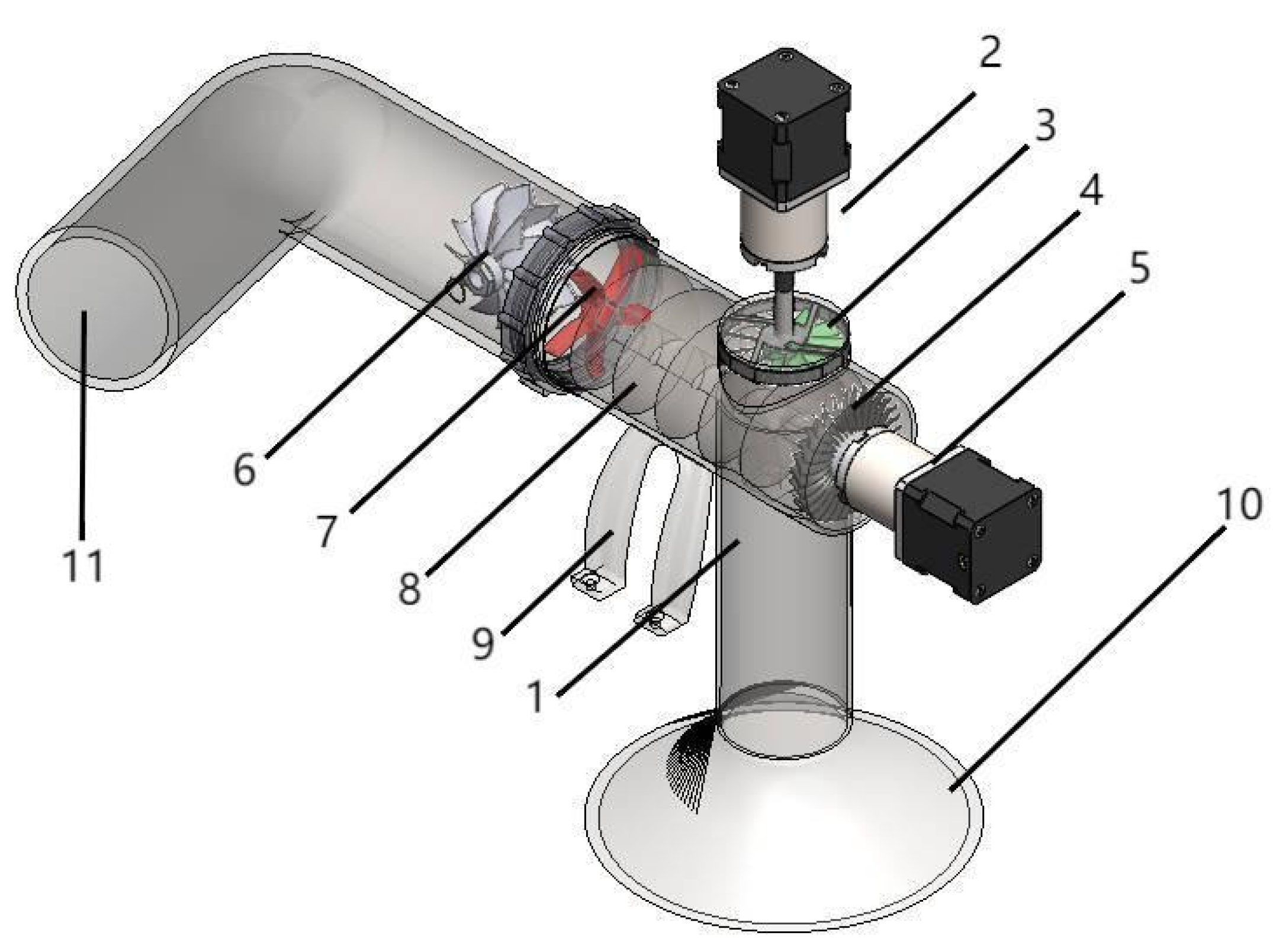
3.3. Fallen Leaf Collection and Recycling Device

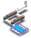
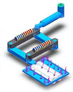
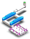
3.3.1. Design of Fallen Leaf Collection and Recycling Device

The litter collection and crushing recovery device comprises an absorption area, a crushing area, and a sending area, as shown in Figure 7.
The specific working principle of the litter collection and crushing recovery device is as follows. The upper motor drives the absorbing fan blade to rotate to produce negative pressure, absorbing the fallen leaves from the suction mouth to the crushing area and crushing the fallen leaves when they reach the position of the reamer. To prevent fallen leaves from falling out of the suction mouth, a blower fan blade is installed on the right side of the reamer to blow the crushed fallen leaves to the left diversion mouth in time. The reamer can crush the fallen leaves to an average diameter of 2 cm to facilitate their decomposition. The shunt fan splits the broken leaves to prevent them from being blocked at the outlet, and the transfer fan installed on the left side sucks the broken leaves from the blowing outlet to prevent them from flowing back. The bending of the blowing outlet is designed for a telescopic hard hose that can arbitrarily adjust the tilt angle of the blowing outlet. The broken leaves are ejected from the crushing device and can be blown to the roadside or collected.

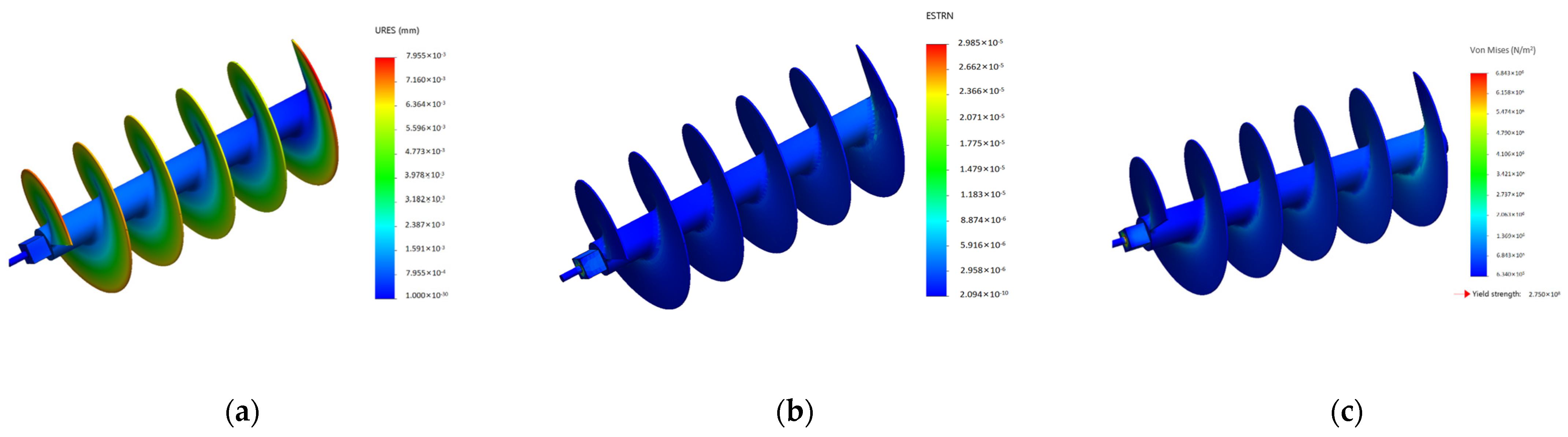
3.3.2. Static Analysis of Fallen Leaf Collection and Recycling Device

Because the reamer is the main part of the leaf-crushing process, its quality affects the crushing and rotting of the fallen leaves, and its life determines the service life of the fallen leaf collection and recycling device; therefore, the reamer requires static analysis. The reamer materials are listed in Table 4.
The boundary conditions of the reamer are set on both sides of the shell for the fixed support. Stress and strain displacement nephograms were derived using finite-element analysis. As shown in Figure 8, the maximum stress on the working device is less than the yield force, and the device structure meets the requirements for different working conditions.
The analysis demonstrated that the stress of the reamer is mainly concentrated in the joint part of the reamer and rotating shaft, and the maximum stress is less than the yield stress to meet the stress requirements of the reamer. The red in the reamer displacement cloud map is mainly concentrated at the cutting edge, and the displacement color distributions of the reamer blade and rotating shaft are within the safe range. Considering that the joint displacement of the reamer satisfies the working requirements, the strain diagram of the reamer is almost blue and is distributed within the safe range.

4. Design of Transmission System

4.1. Design of Power Coupling Device

A dual-motor torque coupling transmission device was developed and used as the transmission system for the small leaf litter collection, crushing, and recovery vehicle. This device can realize the coupling of the dual-motor torque and speed, eliminate the power interruption of the general transmission during shifting, and improve the ride comfort of the vehicle. A structural diagram is shown in Figure 9.

4.2. Analysis of Working Mode of Dynamic Coupling Device

The dynamic coupling system in this study can realize a variety of electric vehicle working modes, including the electric driving mode (single-motor drive, double-motor drive), idle start–stop mode, driving charging mode, parking charging mode, and regenerative braking mode. Twelve gears can be smoothly switched in the electric driving mode to improve the ride comfort of the vehicle.
(1)
Electric driving mode
The motion characteristic equation of the single-row planetary gear mechanism is
n 1 + α n 2 ( 1 + α ) n 3 = 0
In the formula:
  • n1 is the speed of the sun wheel;
  • n2 is the speed of the outer gear ring;
  • n3 is the rotation speed of the planetary frame;
  • Z1 is the number of teeth of the solar wheel;
  • Z2 is the number of teeth of the outer gear ring,  α = Z 2 Z 1 .
(i) The first gear is a forward gear. The second motor works, and the first motor shuts down. Clutches II, IV, and VI are closed, and clutches I, III, V, and VII are disconnected. The third brake is closed, and the first and second brakes are disconnected. The sun wheel is locked by the third brake, and power is input from the planetary frame and output from the outer gear ring for a single-motor drive mode.
(ii) The second gear is a forward gear. The second motor works, and the first motor shuts down. Clutches VI and VII are closed, and clutches I–V are disconnected. The first brake is closed, and the second and third brakes are disconnected. The sun wheel is locked by the first brake. The power is input from the planetary frame and output from the sun wheel for a single-motor drive mode.
(iii) The third gear is a forward gear. The first motor works, and the second motor shuts down. Clutches I, II, IV, VI, and VII are disconnected, and clutches III and V are closed. The first brake is closed, and the second and third brakes are disconnected. The outer gear ring is locked by the first brake. The power is input from the sun wheel, and the output from the planetary frame is in a single drive mode.
(iv) The fourth gear is a forward gear. The first motor works, and the second motor shuts down. Clutches I, IV, and V are closed, and clutches II, III, VI, and VII are disconnected. The third brake is closed, and the first and second brakes are disconnected. The sun wheel is locked by the third brake. The power is input from the outer gear ring and output from the planetary frame, which is a single-motor drive mode.
(v) The fifth gear is a reverse gear. The first motor works, and the second motor shuts down. Clutches I and V–VII are disconnected, and clutches II–IV are closed. The second brake is closed, and the first and third brakes are disconnected. The planetary frame is locked by the second brake. The power of the planetary gear mechanism is input from the sun wheel and output from the outer gear ring, which is a single-motor drive mode.
(vi) The sixth gear is a reverse gear. The first motor works, and the second motor shuts down. Clutches I, IV, and VII are closed, and clutches II, III, V, and VI are disconnected. The second brake is closed, and the first and third brakes are disconnected. The planetary frame is locked by the second brake. The power of the planetary gear mechanism is input from the outer gear ring and output from the sun wheel, which is a single-motor drive mode.
(vii) The seventh gear is a direct gear. The first motor works, and the second motor shuts down. Clutches I and III–V are closed, and clutches II, VI, and VII are disconnected. The first, second, and third brakes are disconnected under the working condition. The two powers are input from the sun wheel and the outer gear ring and output from the planetary frame after synthesis for a single-motor drive mode.
(viii) The eighth gear is a direct gear. The first and second motors work. Clutches I, V, and VII are disconnected, and clutches II–IV and VI are closed. The three brakes are disconnected under the working condition. The two powers are input from the planetary frame and the sun wheel and output from the outer gear ring after synthesis for a double-motor drive mode.
(ix) The ninth gear is a neutral gear. The first motor works, and the second motor shuts down. Clutches I, VI, and VII are disconnected, and clutches II–V are closed. The brake is disconnected under the working condition. The power is input from the sun wheel, and the power is output from the outer gear ring and planetary frame in two ways, which is a single-motor drive mode.
(x) The tenth gear is a neutral gear. The second motor works, and the first motor shuts down. Clutches II, IV, VI, and VII are closed, and clutches I, III, and V are disconnected. The brake is disconnected. The power is input from the planetary frame and output from the sun wheel and outer gear ring in two ways, which is a single-motor drive mode.
(xi) The eleventh gear is a neutral gear. The first motor works, and the second motor shuts down. Clutches I, IV, V, and VII are closed, and clutches II, III, and VI are disconnected. The brake is disconnected. The power is input from the outer gear ring and output from the sun wheel and planetary frame in two ways, which is a single-motor drive mode.
The third motor is always opened in the above 11 gear positions, and the differential is driven by the second drive shaft to ensure that there is no power interruption during shifting and to improve the smoothness of the pure electric vehicle during driving.
(2)
Idle start–stop mode
When the first motor works alone, clutch VI is closed. Clutch VII is disconnected, and the idle start–stop function is achieved by controlling clutch II.
(3)
Driving charging mode
In the electric driving mode gear positions (iii)–(vii), (ix), and (xi), clutch III is closed. The second motor can be used as a generator to charge the battery. In gear positions (i), (ii), and (x), clutch VII is closed, and the first motor can be used as a generator to charge the battery.
(4)
Parking charging mode
During parking, the second motor works separately. Clutch VI is closed, clutch VII is disconnected, and clutch II is disconnected. The first motor can be used as a generator to charge the battery.
(5)
Regenerative braking mode
In working modes (1), (2), and (3), braking energy can be recovered by controlling the first or second motor during deceleration braking to achieve regenerative braking. When only the first motor works to slow down the braking, the second motor is converted into generator mode, and the kinetic energy of the vehicle is converted into electrical energy to be used or stored rather than becoming useless heat. When only the second motor is working, the first motor is converted into generator mode, and the kinetic energy of the vehicle is converted into electrical energy for use or storage.

5. Three-Dimensional-Printing Process and Feasibility Verification of the Model
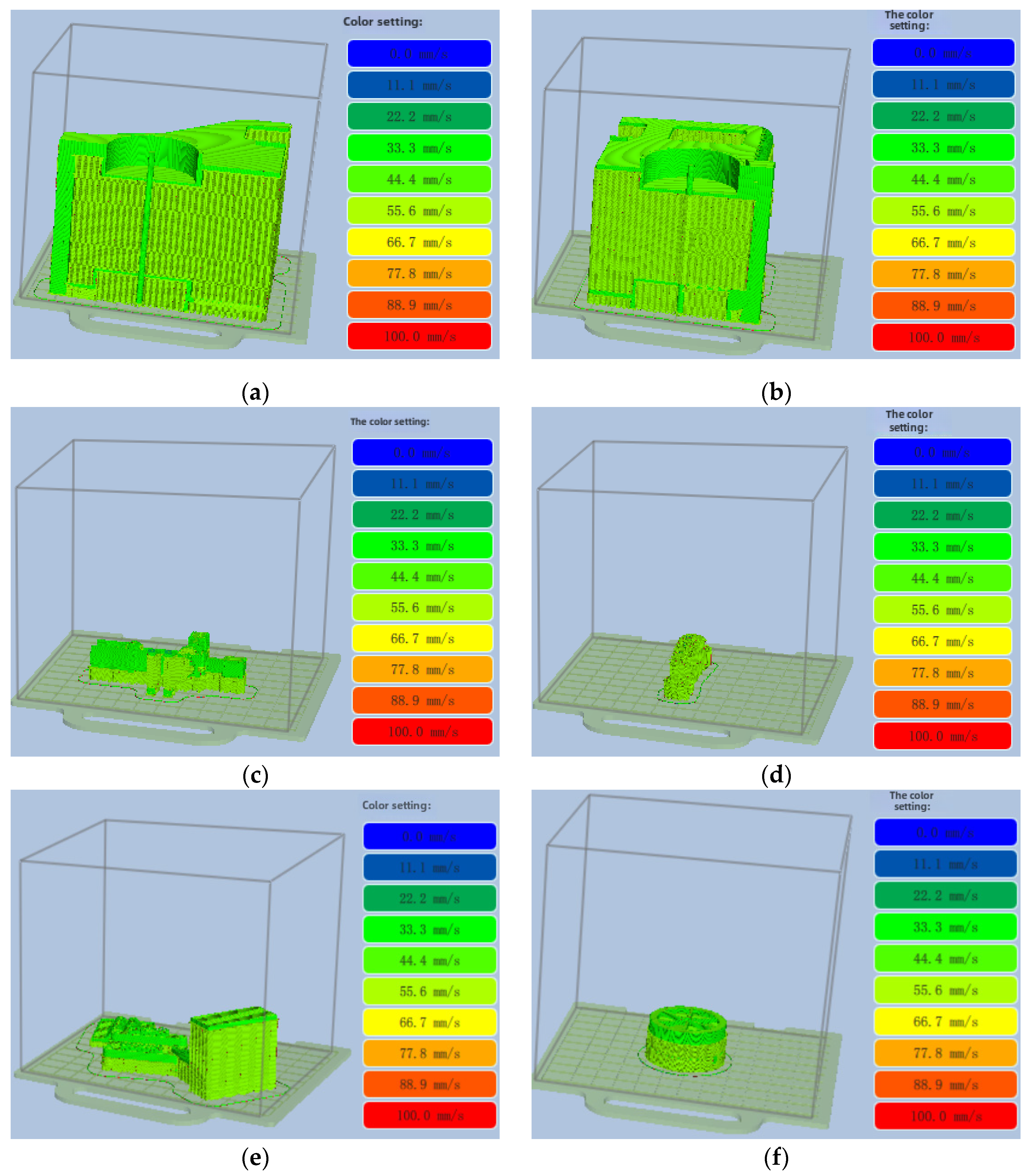
The print scaling ratio of the model was calculated to be 0.5 × 0.5 × 0.8 × 0.7, and the model was divided into 10 parts for printing. The entire body was cut into two parts. The front and back of the body had two windows, and the two sides of the body had four windows to observe the structure of the interior. The retractable collection brush was printed in two parts. The retractable collection brush is flexible; therefore, the connecting shaft, retractable rod, and brush head had to be printed separately. The horizontal pipe needs to be cut to see the reamer and the fan system when printing the crusher. For the wheel, the outer hub was printed, followed by a large wheel model for viewing the internal structure.

5.1. Model Slice

Before slicing, it is necessary to set the model parameters, which are listed in Table 5.
The models were converted into the .STL format and uploaded to the UP Studio system for adjustment. The UP Studio 3 software cut the 3D model into a series of sheets, each representing a cross-section of the model at a certain height. UP Studio generated the print path and support structure based on the printer parameters, such as the nozzle diameter and printing speed. The 3D printer model was set to UP300. A slice state diagram of the model is shown in Figure 10.

5.2. Printing Process

The slice files are exported in the .tsk format. These files contain all the instructions required for the 3D printer. The file is transferred to a 3D printer and prepared for printing. The printing process is started, and the progress can be monitored at any time to ensure that everything is happening as expected. Figure 11 shows the state of the printer.

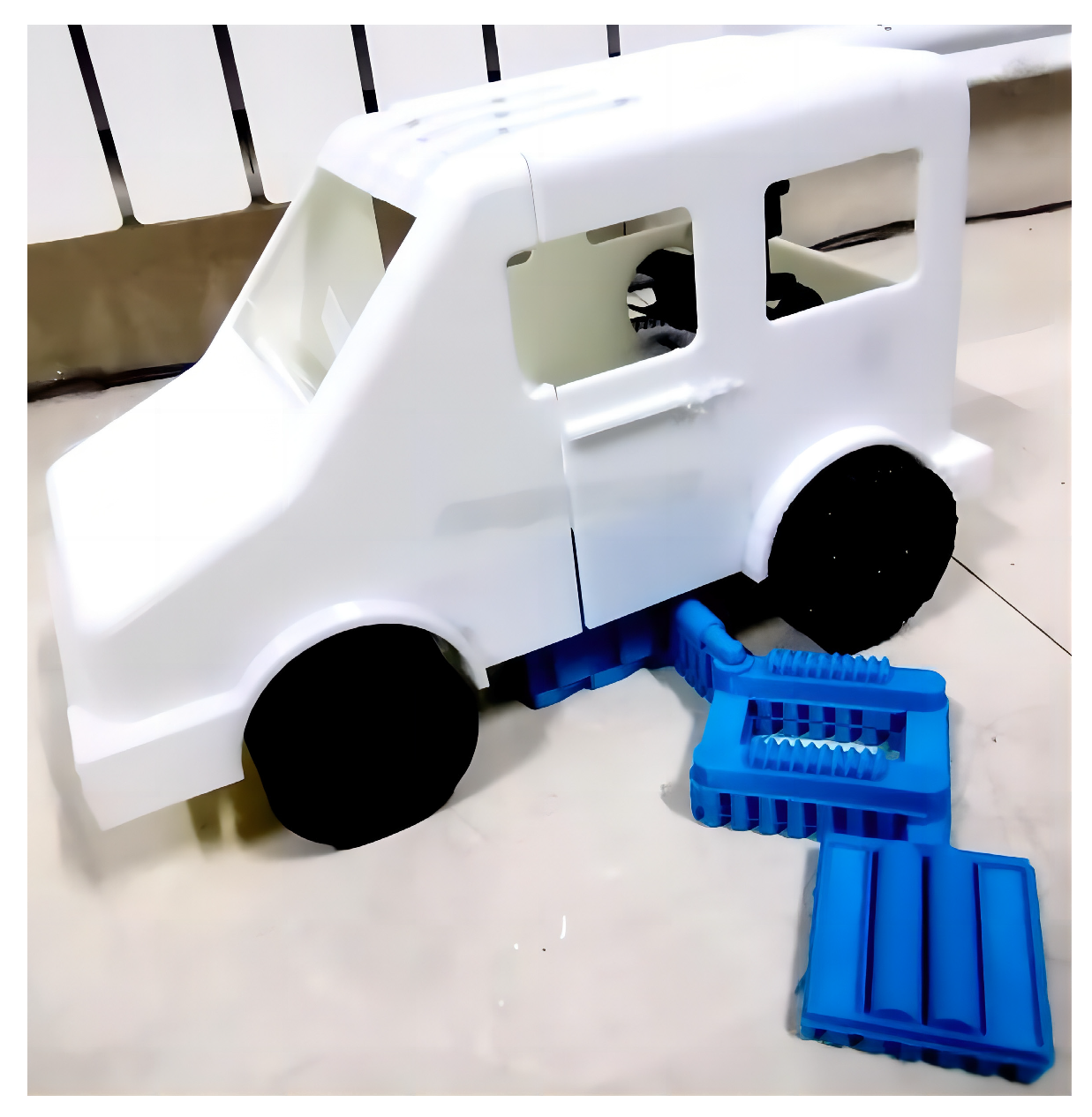
5.3. Part Assembly and Validation Analysis

The printed parts are removed from the support and then assembled. The specific parts are shown in Figure 12.
The printed parts were assembled to verify the original design concept. Some problems with the design of the model were identified. When the retractable collection brush was designed, only cases in which the two structures work together or alone were considered. After the printed model was observed, the leaf-blowing pipe was extended to a height of 30 cm above the ground outside the vehicle, and the height of the retractable collection brush was 40 cm above the ground. When the two mechanisms work together, the retractable collection brush hits the leaf-blowing pipe when it contracts, causing an irreversible impact on the device. Therefore, the rotation angle of the telescopic side brush on the right side of the improved design is 135°, and it stops moving and turns when it is 10° from the leaf-blowing pipe [19,20,21]. The finished product is shown in Figure 13.
The successful completion of the 3D printing process proves that the device can be implemented under the conditions required for the assembly and manufacturing of physical objects.

6. Conclusions

In this paper, to resolve fallen leaf pollution in the environment, a litter sweeping and crushing recovery vehicle is designed. It not only solves the problem of environmental pollution but also recycles the fallen leaves and realizes the value of the fallen leaves.
(1)
The mechanical structure is designed and modeled, and the strength and stiffness of key components are verified via finite element analysis. The results show that the maximum stress of the wheel appears on the expansion hob; the maximum stress of the telescopic collecting brush appears at the connection between the connecting rod and the rolling brush. The maximum stress of the reamer occurs at the joint between the reamer and the shaft.
(2)
The transmission system of the vehicle is designed, and a dual motor torque coupling transmission without power interruption is designed. Using the working principle of the planetary gear mechanism, 12 gears can be switched, and five working modes can be selected.
(3)
The overall model was 3D printed, from model segmentation by area, model layered slicing, model parts printing and forming to the assembly of the overall model, which verified that the initial design concept met the assembly and production requirements of the device, and then found and improved the design problems in the process of assembling the model in terms of time.
Planned future work includes further tests, such as tests and experiments on wheel movement, to ensure that the motion performance of the device is adequate. Subsequently, a full-scale prototype should be constructed.
This study addressed the design of a fallen leaf collection, crushing, and recycling vehicle. The main design steps were carefully designed to achieve the integrated operation of the collection, crushing, and recycling of fallen leaves. The collected leaves are decomposed and fermented to be used for fertilization. A prototype was manufactured using 3D printing technology to verify the feasibility of its assembly. The rotation angle of the retractable collection brush was improved through testing. Planned future work includes further tests, such as tests and experiments on wheel movement, to ensure that the motion performance of the device is adequate. Subsequently, a full-scale prototype should be constructed.

Author Contributions

Conceptualization, X.Z.; methodology, H.L.; software, X.Z.; validation, X.Z. and C.L.; formal analysis, W.H.; investigation, W.H.; resources, C.L.; data curation, Z.Z.; writing—original draft preparation, X.Z.; writing—review and editing; visualization, A.G.; supervision, A.G.; project administration, L.Y.; funding acquisition, A.G. All authors have read and agreed to the published version of the manuscript.

Funding

This work is supported by the Natural Science Foundation of Shandong Province (ZR2023ME154), and the Training Program of Innovation and Entrepreneurship for Undergraduates (Grant No. CXCY2024135, CXCY2024138, CXCY2022493).

Data Availability Statement

The data presented in this study are available upon request from the corresponding author. The data are not publicly available due to privacy.

Conflicts of Interest

The authors declare no conflicts of interest.

References

  1. Zhou, T.; Wang, J. Current situation of urban landscaping waste treatment and countermeasures of resource utilization. Guide Econ. Res. 2017, 15, 147–148. [Google Scholar]
  2. Tang, Z.P. Ways and strategies of garden waste resource utilization. Rural. Sci. Technol. 2021, 12, 99–100. [Google Scholar]
  3. Guan, X. Research on Design and Simulation of Working Device of Highway Garbage Sweeper. Master’s Thesis, Chang’an University, Xi’an, China, 2021. [Google Scholar]
  4. Qiao, C. Research and Design of Garbage Sweeper Based on Kansei Engineering. Master’s Thesis, Chang’an University, Xi’an, China, 2020. [Google Scholar]
  5. Ma, J.; Sun, S.; Rui, H. Review of Academic Research on Road Construction Machinery in China. China J. Highw. Transp. 2018, 31, 1–164. [Google Scholar]
  6. Li, S.; Peng, C.; Huang, D.; Hu, J.W. Design of a new type of grass leaf sweeper based on UG. Times Agric. Mach. 2017, 44, 96–98. [Google Scholar]
  7. Lv, L.; Zhang, P. Production of “Integrated machine for collecting and pressing fallen Leaves”. Sci. Technol. Innov. 2019, 12, 146–147. [Google Scholar]
  8. Natsu, N. Development of an Autonomous Blower Robot for Cleaning up and Collecting Fallen Leaves. In Proceedings of the 2023 IEEE 19th International Conference on Automation Science and Engineering (CASE), Auckland, New Zealand, 26 August–30 August 2023; IEEE: Washington, DC, USA, 2023; pp. 1–6. [Google Scholar]
  9. Zhong, D.; Qiao, X. Structural Design of Leaf Sweeping Vehicle. In Proceedings of the International Conference on Industrial Design and Environmental Engineering, IDEE, Zhengzhou, China, 24–26 November 2023. [Google Scholar]
  10. Lee, W.-C.; Chiang, W.-H. Development of a Leaf-Sweeping Robot. In Proceedings of the 2022 IEEE 5th International Conference on Industrial Cyber-Physical Systems (ICPS), Coventry, UK, 24–26 May 2022; pp. 1–5. [Google Scholar]
  11. Delle Donne, D.; Di Tomaso, V. Optimizing leaf sweep and collection in the Argentine city of Trenque Lauquen. Waste Manag. Res. 2021, 39, 209–220. [Google Scholar] [CrossRef] [PubMed]
  12. Yi, L.; Le, A.V.; Hayat, A.A.; Borusu, C.S.; Mohan, R.E.; Nhan, N.H.K.; Kandasamy, P. Reconfiguration During Locomotion by Pavement Sweeping Robot with Feedback Control from Vision System. IEEE Access 2020, 8, 113355–113370. [Google Scholar] [CrossRef]
  13. Hsia, S.C.; Wang, S.H.; Yeh, J.Y.; Chang, C.Y. A Smart Leaf Blow Robot Based on Deep Learning Model. IEEE Access 2023, 11, 111956–111962. [Google Scholar] [CrossRef]
  14. Li, Y.; Zhang, X. Design and analysis of Walking intelligent Leaf cleaning Robot. Digit. World 2019, 1, 11. [Google Scholar]
  15. Sheng, X.; Guo, A.; Guo, S.; Sui, S.; Yang, W.; Tang, R.; Li, X.; Qu, P.; Wang, M.; Lin, X. Laser powder bed fusion for the fabrication of triply periodic minimal surface lattice structures: Synergistic macroscopic and microscopic optimization. J. Manuf. Process. 2024, 119, 179–192. [Google Scholar] [CrossRef]
  16. Guo, A.; Kong, D.; Zhou, X.; Kong, H.; Qu, P.; Wang, S.; Wang, H.; Hu, Y. Method for preparing damage-resistant 3D-printed ceramics via interior-to-exterior strengthening and toughening. Addit. Manuf. 2022, 60, 103272. [Google Scholar] [CrossRef]
  17. Kong, D.; Guo, A.; Wu, H.; Li, X.; Wu, J.; Hu, Y.; Qu, P.; Wang, S.; Guo, S. Four-dimensional printing of polymer-derived ceramics with high-resolution, reconfigurability, and shape memory effects. Addit. Manuf. 2024, 83, 104050. [Google Scholar] [CrossRef]
  18. Wu, H.; Guo, A.; Kong, D.; Li, X.; Wu, J.; Wang, H.; Qu, P.; Wang, S.; Guo, S.; Liu, C.; et al. Nacre-like carbon fiber-reinforced biomimetic ceramic composites: Fabrication, microstructure, and mechanical performance. Ceram. Int. 2024, 50, 25388–25399. [Google Scholar] [CrossRef]
  19. He, J.; Lv, X. Structural color printing and evaluation based on 3D printing. Pigment. Resin Technol. 2024, 53, 502–509. [Google Scholar] [CrossRef]
  20. Bestiara, F.; Saptaji, K.; Dewi, T.K.; Triawan, F.; Ramadhan, A.I.; Azhari, A. Development of the Extrusion Based Food 3D Printer Machine by Modifying Fused Deposition Modelling (FDM) 3D Printer. Appl. Mech. Mater. 2024, 921, 57–65. [Google Scholar] [CrossRef]
  21. Chen, M.Y.; Pang, R.; Lai, M.K. Investigation on Layer Thickness on Mechanical Properties and Dimension Accuracy in Fused Deposition Modelling 3D Printing. Mater. Sci. Forum 2024, 1118, 99–104. [Google Scholar] [CrossRef]
Figure 1. Overall structure of small fallen leaf collection, crushing, and recycling vehicle. 1. Telescopic hob wheel; 2. Telescopic side brush; 3. Electromechanical coupling system; 4. Collection of fallen leaves for crushing and recycling institutions.
Processes 12 02011 g001
Figure 2. Structure diagram of telescopic hob wheel based on iris structure. 1. Pinion; 2. Gear ring; 3. Hob; 4. Inner hub of iris; 5. Motor pinion; 6. NEMA+17 stepper motor.
Processes 12 02011 g002
Figure 3. Wheel structure diagram of retractable hob controlled by gear transmission based on iris structure: (a) diagram of wheel model on uneven road surface and (b) diagram of wheel model on smooth road.
Processes 12 02011 g003
Figure 4. Cloud maps of wheel stress, strain, and displacement: (a) displacement of the wheel, (b) strain of the wheel, and (c) stress of the wheel.
Processes 12 02011 g004
Figure 5. Structure diagram of retractable brush: (a) side view and (b) front view. 1. Chassis; 2, 5, 16, 20. Hydraulic cylinder; 3, 18. Hydraulic rotation shaft; 4, 19. Motor; 6, 10, 13, 15. Long connecting rod; 7, 11, 17. Short connecting rod with brush; 8, 12, 26, 27. Roller brush; 9, 14, 25. Short connecting rod; 11. Brush short connecting rod; 16. Hydraulic cylinder; 21–24. Current solenoid.
Processes 12 02011 g005
Figure 6. Cloud maps of retractable collection brush stress, strain, and displacement: (a) displacement of the retractable collection brush, (b) strain of the retractable collection brush, and (c) stress of the retractable collection brush.
Processes 12 02011 g006
Figure 7. Structure diagram of litter collection, crushing, and recycling device. 1. Shell; 2. Upper motor; 3. Absorption fan blade; 4. Blower fan blade; 5. Right motor; 6. Transfer fan blade; 7. Shunt fan; 8. Reamer; 9. Support frame; 10. Leaf suction mouth; 11. Blowing outlet.
Processes 12 02011 g007
Figure 8. Cloud map of reamer stress, strain, and displacement: (a) displacement of the reamer, (b) strain of the reamer, and (c) stress of the reamer.
Processes 12 02011 g008
Figure 9. Structure diagram of power coupling device. 1. First drive shaft; 2. Second drive shaft; 3. First motor; 4. Second motor; 5. Third motor; 6. Differential; 7. Planetary gear mechanism; 8. Sun gear; 9. Planetary rack; 10. Tooth ring; 11. Planetary gear; 12. Third drive shaft; 13. Clutch III; 14. Clutch VI; 15. Clutch I; 16. Clutch IV; 21. Sun wheel transmission components; 22. Planetary frame transmission components; 23. Gear ring transmission components; 24. First brake; 25. Second brake; 26. Third brake; 21-4. Clutch VII; 22-3. Clutch V; 23-4. Clutch II; 17 (18, 19, 20, 21-1, 21-2, 21-3, 22-1, 22-2, 23-1, 23-2, 23-3). Transmission gear.
Processes 12 02011 g009
Figure 10. Model slice state diagram: (a) front of car, (b) rear of car, (c) rear of pulverizer, (d) front of pulverizer, (e) retractable collection brush, and (f) wheel.
Processes 12 02011 g010
Figure 11. Photographs of printer status: (a) three-dimensional printer, (b) printing process.
Processes 12 02011 g011
Figure 12. The 3D-printed parts.
Processes 12 02011 g012
Figure 13. Integral 3D-printed model.
Processes 12 02011 g013
Table 1. Main technical parameters of device.
Technical ParameterQuantity Value and Selection
Working weight1480.0 kg
Sweep width (one side brush)1.5 m
Side brush expansion range0.8 m
Side brush ground clearance10 mm
Ground clearance of absorption pipe50 mm
Absorption pipe diameter0.8 m
Reamer length0.8 m
Trunk capacity400 L
Maximum diameter of wheel hob0.85 m
Vehicle length2582 mm
Vehicle width1142 mm
Vehicle height1410 mm
Table 2. Material properties of the wheel.
Material Property
NameStainless steel (ferrite)
Model typeLinear elastic homology
Yield strength1.72339 × 108 N/m2
Tensile strength5.13613 × 108 N/m2
Elastic modulus2 × 1011 N/m2
Poisson’s ratio0.28
Mass density7800 kg/m3
Shear modulus7.7 × 1010 N/m2
Thermal expansion coefficient1.1 × 10−5/K
Table 3. Material properties and selection of retractable brush.
ModelMaterial Property
Processes 12 02011 i001
Roller
NameNatural rubber
Model typeLinear elastic homology
Tensile strength2 × 107 N/m2
Elastic modulus10,000 N/m2
Poisson’s ratio0.45
Mass density960 kg/m3
Processes 12 02011 i002
Connecting rod
NameStainless steel (ferrite)
Model typeLinear elastic homology
Yield strength1.72339 × 108 N/m2
Tensile strength5.13613 × 108 N/m2
Elastic modulus2 × 1011 N/m2
Poisson’s ratio0.28
Mass density7800 kg/m3
Shear modulus7.7 × 1010 N/m2
Thermal expansion coefficient1.1 × 10−5/K
Processes 12 02011 i003
Current solenoid
NameDuctile iron
Model typeLinear elastic homology
Yield strength5.51485 × 108 N/m2
Tensile strength8.61695 × 108 N/m2
Elastic modulus1.2 × 1011 N/m2
Poisson’s ratio0.31
Mass density7100 kg/m3
Shear modulus7.7 × 1010 N/m2
Thermal expansion coefficient1.1 × 10−5/K
Table 4. Material properties of the reamer.
Material Property
NameA286 iron base superalloy
Model typeLinear elastic homology
Default failure criteriaMaximum von Mises stress
Yield strength2.75 × 108 N/m2
Tensile strength6.2 × 108 N/m2
Elastic modulus2.01 × 1011 N/m2
Poisson’s ratio0.31
Mass density7920 kg/m3
Shear modulus7.7 × 1010 N/m2
Thermal expansion coefficient1.65 × 10−5/K
Table 5. Material properties of the reamer.
Layer Thickness0.2 mm
Interlayer mass0.2 mm
Density support angle30°
Number of floors4
Minimum area5
Packing density25%
Support density20%
Bond strength30%
Disclaimer/Publisher’s Note: The statements, opinions and data contained in all publications are solely those of the individual author(s) and contributor(s) and not of MDPI and/or the editor(s). MDPI and/or the editor(s) disclaim responsibility for any injury to people or property resulting from any ideas, methods, instructions or products referred to in the content.

