Electromagnetically Induced Grating of Surface Polaritons via Coherent Population Oscillation


Abstract
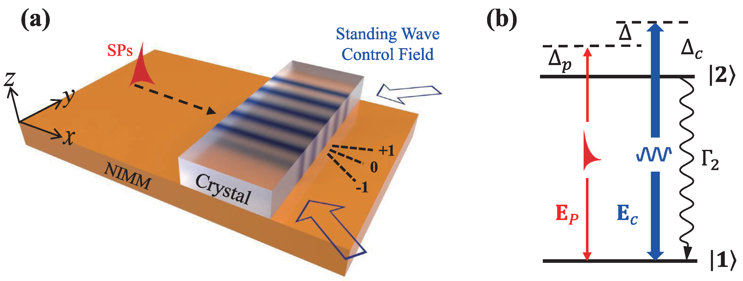
:1. Introduction
2. Theoretical Model
3. Derivation of the Main Equation
3.1. The Solutions of the Bloch Equation
3.2. Fraunhofer Diffraction of the Low Loss SPs
4. Results and Discussion
4.1. Absorption Grating of SPs Based on Linear Excitations of the System
4.2. Phase Grating of SPs Based on the Nonlinear Response of the System
5. Conclusions
Author Contributions
Funding
Institutional Review Board Statement
Informed Consent Statement
Data Availability Statement
Conflicts of Interest
Appendix A. TM Mode of the Electromagnetic Field
Appendix B. Expressions Of Each Order Solution
References
- Born, M.; Wolf, E. Principles of Optics, 7th (expanded) ed.; Press Syndicate of the University of Cambridge: Cambridge, UK, 1999. [Google Scholar]
- Tachikawa, Y. Spectral Analysis of Transmission Echelon Grating Filters for Photonic Networks. Opt. Rev. 1999, 6, 131–138. [Google Scholar] [CrossRef]
- Khoo, I.; Chen, C.; Ho, T.J. High efficiency holographic Bragg grating with optically prolonged memory. Sci. Rep. 2016, 6, 36148. [Google Scholar] [CrossRef] [PubMed]
- Fleischhauer, M.; Imamoglu, A.; Marangos, J.P. Electromagnetically induced transparency: Optics in coherent media. Rev. Mod. Phys. 2005, 77, 633. [Google Scholar] [CrossRef]
- Ourir, A.; Gallas, B.; Becerra, L.; De Rosny, J.; Dahoo, P.R. Electromagnetically Induced Transparency in Symmetric Planar Metamaterial at THz Wavelengths. Photonics 2015, 2, 308–316. [Google Scholar] [CrossRef]
- Liang, S.; Yu, Q.; Lei, X.; Ning, S.; Li, C.; Zhang, Y.; Zhang, Z. Experimental Realization of Reconfigurable Photonic Lattices in Coherent Rydberg Atomic Vapors. Photonics 2022, 9, 422. [Google Scholar] [CrossRef]
- Ling, H.Y.; Li, Y.Q.; Xiao, M. Electromagnetically induced grating: Homogeneously broadened medium. Phys. Rev. A 1998, 57, 1338. [Google Scholar] [CrossRef]
- Mitsunaga, M.; Imoto, N. Observation of an electromagnetically induced grating in cold sodium atoms. Phys. Rev. A 1999, 59, 4773. [Google Scholar] [CrossRef]
- Tabosa, J.W.R.; Lezama, A.; Cardoso, G.C. Transient Bragg diffraction by a transferred population grating: Application for cold atoms velocimetry. Opt. Commun. 1999, 165, 59–64. [Google Scholar] [CrossRef]
- Cardoso, G.C.; Tabosa, J.W.R. Electromagnetically induced gratings in a degenerate open two-level system. Phys. Rev. A 2002, 65, 033803. [Google Scholar] [CrossRef]
- Brown, A.W.; Xiao, M. All-optical switching and routing based on an electromagnetically induced absorption grating. Opt. Lett. 2005, 30, 699–701. [Google Scholar] [CrossRef] [Green Version]
- Brown, A.W.; Xiao, M.T. Frequency detuning and power dependence of reflection from an electromagnetically induced absorption grating. J. Mod. Opt. 2005, 52, 2365–2371. [Google Scholar] [CrossRef]
- de Araujo, L.E. Electromagnetically induced phase grating. Opt. Lett. 2008, 35, 977–979. [Google Scholar] [CrossRef] [PubMed]
- Dutta, B.K.; Mahapatra, P.K. Electromagnetically induced grating in a three-level Ξ -type system driven by a strong standing wave pump and weak probe fields. J. Phys. B At. Mol. Opt. Phys. 2006, 39, 1145. [Google Scholar] [CrossRef]
- Xiao, Z.H.; Shin, S.G.; Kim, K. An electromagnetically induced grating by microwave modulation. J. Phys. B At. Mol. Opt. Phys. 2010, 43, 161004. [Google Scholar] [CrossRef]
- Carvalho, S.A.; de Araujo, L.E. Electromagnetically-induced phase grating: A coupled-wave theory analysis. Opt. Express 2011, 19, 1936–1944. [Google Scholar] [CrossRef]
- Zhao, L.; Duan, W.; Yelin, S.F. Generation of tunable-volume transmission-holographic gratings at low light levels. Phys. Rev. A 2011, 84, 033806. [Google Scholar] [CrossRef]
- Ba, N.; Wu, X.Y.; Liu, X.J.; Zhang, S.Q.; Wang, J. Electromagnetically induced grating in an atomic system with a static magnetic field. Opt. Commun. 2012, 285, 3792–3797. [Google Scholar] [CrossRef]
- Wan, R.G.; Kou, J.; Jiang, L.; Jiang, Y.; Gao, J.Y. Electromagnetically induced grating via enhanced nonlinear modulation by spontaneously generated coherence. Phys. Rev. A 2011, 83, 033824. [Google Scholar] [CrossRef]
- Xie, B.; Cai, X.; Xiao, Z.H. Electromagnetically induced phase grating controlled by spontaneous emission. Opt. Commun. 2012, 285, 133–135. [Google Scholar] [CrossRef]
- Sahrai, M.; Mahmoudi, M. The impact of decay-induced interference on transient behaviours of the dispersion and the absorption. J. Phys. B At. Mol. Opt. Phys. 2009, 42, 235503. [Google Scholar] [CrossRef]
- Cheng, G.L.; Zhong, W.X.; Chen, A.X. Phonon induced phase grating in quantum dot system. Opt. Express 2015, 23, 9870–9880. [Google Scholar] [CrossRef] [PubMed]
- Kuang, S.Q.; Jin, C.S.; Li, C. Gain-phase grating based on spatial modulation of active Raman gain in cold atoms. Phys. Rev. A 2011, 84, 033831. [Google Scholar] [CrossRef]
- Hang, C.; Li, W.; Huang, G. Nonlinear light diffraction by electromagnetically induced gratings with PT symmetry in a Rydberg atomic gas. Phys. Rev. A 2019, 100, 043807. [Google Scholar] [CrossRef]
- Shui, T.; Yang, W.X.; Liu, S.; Li, L.; Zhu, Z. Asymmetric diffraction by atomic gratings with optical PT symmetry in the Raman-Nath regime. Phys. Rev. A 2018, 97, 033819. [Google Scholar] [CrossRef]
- Arkhipkin, V.G.; Myslivets, S.A. One-and two-dimensional Raman-induced diffraction gratings in atomic media. Phys. Rev. A 2018, 98, 013838. [Google Scholar] [CrossRef]
- Bozorgzadeh, F.; Sahrai, M.; Khoshsima, H. Controlling the electromagnetically induced grating via spontaneously generated coherence. Eur. Phys. J. D 2016, 70, 191. [Google Scholar] [CrossRef]
- Naseri, T.; Sadighi-Bonabi, R. Electromagnetically induced phase grating via population trapping condition in a microwave-driven four-level atomic system. J. Opt. Soc. Am. B 2014, 31, 2879–2884. [Google Scholar] [CrossRef]
- Shui, T.; Yang, W.X.; Li, L.; Wang, X. Lop-sided Raman–Nath diffraction in PT-antisymmetric atomic lattices. Opt. Lett. 2019, 44, 2089–2092. [Google Scholar] [CrossRef]
- Zhang, H.; Yuan, J.; Dong, S.; Wu, C.; Wang, L. Observation of an Electromagnetically Induced Grating in Cold 85Rb Atoms. Appl. Sci. 2020, 10, 5740. [Google Scholar] [CrossRef]
- Naseri, T. Two-dimensional induced grating in Rydberg atoms via microwave field. Eur. Phys. J. Plus 2019, 134, 530. [Google Scholar] [CrossRef]
- Asghar, S.; Qamar, S.; Qamar, S. Electromagnetically induced grating with Rydberg atoms. Phys. Rev. A 2016, 94, 033823. [Google Scholar] [CrossRef]
- Bozorgzadeh, F.; Sahrai, M. All-optical grating in a V+Ξ configuration using a Rydberg state. Phys. Rev. A 2018, 98, 043822. [Google Scholar] [CrossRef]
- Ma, D.; Yu, D.; Zhao, X.D.; Qian, J. Unidirectional and controllable higher-order diffraction by a Rydberg electromagnetically induced grating. Phys. Rev. A 2019, 99, 033826. [Google Scholar] [CrossRef]
- Liu, J.; Liu, N.; Shan, C.; Liu, T.; Li, H.; Zheng, A.; Xie, X.T. Electromagnetically induced grating in a crystal of molecular magnets system. Phys. Lett. A 2016, 380, 2458–2464. [Google Scholar] [CrossRef]
- Shui, T.; Li, L.; Wang, X.; Yang, W.X. One-and two-dimensional electromagnetically induced gratings in an Er3+-doped yttrium aluminum garnet crystal. Sci. Rep. 2020, 10, 4019. [Google Scholar] [CrossRef]
- Meng, C.; Shui, T.; Yang, W.X.; Tian, Y.H. Control of an electromagnetically induced grating by Er3+ ion concentration in an Er3+-doped YAG crystal. J. Opt. Soc. Am. B 2021, 38, 2036–2042. [Google Scholar] [CrossRef]
- Naseri, T. Optical properties and electromagnetically induced grating in a hybrid semiconductor quantum dot-metallic nanorod system. Phys. Lett. A 2020, 384, 126164. [Google Scholar] [CrossRef]
- Zhou, F.; Qi, Y.; Sun, H.; Chen, D.; Yang, J.; Niu, Y.; Gong, S. Electromagnetically induced grating in asymmetric quantum wells via Fano interference. Opt. Express 2013, 21, 12249–12259. [Google Scholar] [CrossRef] [PubMed]
- Ba, N.; Wang, L.; Wu, X.Y.; Liu, X.J.; Wang, H.H.; Cui, C.L.; Li, A.J. Electromagnetically induced grating based on the giant Kerr nonlinearity controlled by spontaneously generated coherence. Appl. Opt. 2013, 52, 4264–4272. [Google Scholar] [CrossRef]
- Gao, J.; Hang, C.; Huang, G. Linear and nonlinear Bragg diffraction by electromagnetically induced gratings with PT symmetry and their active control in a Rydberg atomic gas. Phys. Rev. A 2022, 105, 063511. [Google Scholar] [CrossRef]
- Hu, Y.; Cheng, G.; Chen, A. Tunneling-induced phase grating in quantum dot molecules. Opt. Express 2020, 28, 29805–29814. [Google Scholar] [CrossRef] [PubMed]
- Liu, Z.Z.; Chen, Y.Y.; Yuan, J.Y.; Wan, R.G. Two-dimensional electromagnetically induced grating via nonlinear modulation in a five-level atomic system. Opt. Commun. 2017, 402, 545–550. [Google Scholar] [CrossRef]
- Liu, Y.M.; Gao, F.; Wu, J.H.; Artoni, M.; La Rocca, G.C. Lopsided diffractions of distinct symmetries in two-dimensional non-Hermitian optical gratings. Phys. Rev. A 2019, 100, 043801. [Google Scholar] [CrossRef]
- Asadpour, S.H.; Kirova, T.; Qian, J.; Hamedi, H.R.; Juzeliūnas, G.; Paspalakis, E. Azimuthal modulation of electromagnetically induced grating using structured light. Sci. Rep. 2021, 11, 20721. [Google Scholar] [CrossRef] [PubMed]
- Yuan, J.; Dong, S.; Wu, C.; Wang, L.; Xiao, L.; Jia, S. Optically tunable grating in a V+Ξ configuration involving a Rydberg state. Opt. Express 2020, 28, 23820–23828. [Google Scholar] [CrossRef]
- Yuan, J.; Wu, C.; Wang, L.; Chen, G.; Jia, S. Observation of diffraction pattern in two-dimensional optically induced atomic lattice. Opt. Lett. 2019, 44, 4123–4126. [Google Scholar] [CrossRef]
- Yuan, J.; Zhang, H.; Wu, C.; Wang, L.; Xiao, L.; Jia, S. Tunable optical vortex array in a two-dimensional electromagnetically induced atomic lattice. Opt. Lett. 2021, 46, 4184–4187. [Google Scholar] [CrossRef]
- Gramotnev, D.K.; Bozhevolnyi, S.I. Plasmonics beyond the diffraction limit. Nat. Photonics 2010, 4, 83–91. [Google Scholar] [CrossRef]
- Kamli, A.; Moiseev, S.A.; Sanders, B.C. Coherent control of low loss surface polaritons. Phys. Rev. Lett. 2008, 101, 263601. [Google Scholar] [CrossRef]
- Zhou, Y.; Liu, Q.; Wang, C.K.; Tan, C. Trapping effect and trajectory control of surface plasmon polaritons in a metal-dielectric-metal waveguide. Phys. Rev. A 2020, 102, 063516. [Google Scholar] [CrossRef]
- Liu, Q.; Li, N.; Tan, C. All-optical logic gate based on manipulation of surface polaritons solitons via external gradient magnetic fields. Phys. Rev. A 2020, 101, 023818. [Google Scholar] [CrossRef]
- Siomau, M.; Kamli, A.A.; Moiseev, S.A.; Sanders, B.C. Entanglement creation with negative index metamaterials. Phys. Rev. A 2012, 85, 050303. [Google Scholar] [CrossRef]
- Lavoie, B.R.; Leung, P.M.; Sanders, B.C. Slow light with three-level atoms in metamaterial waveguides. Phys. Rev. A 2013, 88, 023860. [Google Scholar] [CrossRef]
- Asgarnezhad-Zorgabad, S.; Berini, P.; Sanders, B.C. Polaritonic frequency-comb generation and breather propagation in a negative-index metamaterial with a cold four-level atomic medium. Phys. Rev. A 2019, 99, 051802. [Google Scholar] [CrossRef]
- Asgarnezhad-Zorgabad, S.; Sanders, B.C. Nonlinear frequency conversions via weak surface polaritonic wave breaking in a hybrid plasmonic waveguide. Opt. Lett. 2020, 45, 5432–5435. [Google Scholar] [CrossRef]
- Tan, C.; Huang, G. Surface polaritons in a negative-index metamaterial with active Raman gain. Phys. Rev. A 2015, 91, 023803. [Google Scholar] [CrossRef]
- Asgarnezhad-Zorgabad, S.; Sadighi-Bonabi, R.; Sanders, B.C. Excitation and propagation of surface polaritonic rogue waves and breathers. Phys. Rev. A 2018, 98, 013825. [Google Scholar] [CrossRef]
- Moiseev, S.A.; Kamli, A.A.; Sanders, B.C. Low-loss nonlinear polaritonics. Phys. Rev. A 2010, 81, 033839. [Google Scholar] [CrossRef]
- Tan, C.; Li, N.; Xu, D.; Chen, Z. Spatial focusing of surface polaritons based on cross-phase modulation. Results Phys. 2021, 27, 104531. [Google Scholar] [CrossRef]
- Tian, X.; Zhang, Y.; Duan, Y.; Zhou, Y.; Tan, C. Propagation and excitation properties of nonlinear surface plasmon polaritons in a rectangular barrier. Phys. E Low-Dimens. Syst. Nanostruct. 2022, 144, 115417. [Google Scholar] [CrossRef]
- Huang, G.; Deng, L.; Payne, M.G. Dynamics of ultraslow optical solitons in a cold three-state atomic system. Phys. Rev. E 2005, 72, 016617. [Google Scholar] [CrossRef] [PubMed]
- Tan, C.; Huang, G. Superluminal surface polaritonic solitons at weak light level via coherent population oscillation. Phys. Rev. A 2014, 89, 033860. [Google Scholar] [CrossRef]
- Boyd, R.W.; Raymer, M.G.; Narum, P.; Harter, D.J. Four-wave parametric interactions in a strongly driven two-level system. Phys. Rev. A 1981, 24, 411. [Google Scholar] [CrossRef]
- Li, L.; Zhu, C.; Deng, L.; Huang, G. Electromagnetically induced transparency and nonlinear pulse propagation in an atomic medium confined in a waveguide. J. Opt. Soc. Am. B 2013, 30, 197–204. [Google Scholar] [CrossRef]
- Beil, F.; Klein, J.; Nikoghosyan, G. Electromagnetically induced transparency and retrieval of light pulses in a Λ -type and a Λ-type level scheme in Pr3+:Y2SiO5. J. Phys. B At. Mol. Opt. Phys. 2008, 41, 074001. [Google Scholar] [CrossRef]
- Zhou, Y.; Chu, L.; Liu, Q.; Wang, C.K.; Tan, C. Analysis of quantum interference properties in Λ-and V-type schemes in rare-earth-ion-doped crystal with inhomogeneous broadening. J. Opt. Soc. Am. B 2019, 36, 2534–2544. [Google Scholar] [CrossRef]


Publisher’s Note: MDPI stays neutral with regard to jurisdictional claims in published maps and institutional affiliations. |
© 2022 by the authors. Licensee MDPI, Basel, Switzerland. This article is an open access article distributed under the terms and conditions of the Creative Commons Attribution (CC BY) license (https://creativecommons.org/licenses/by/4.0/).
Share and Cite
Duan, Y.; Liu, S.; Tan, C. Electromagnetically Induced Grating of Surface Polaritons via Coherent Population Oscillation. Photonics 2022, 9, 697. https://doi.org/10.3390/photonics9100697
Duan Y, Liu S, Tan C. Electromagnetically Induced Grating of Surface Polaritons via Coherent Population Oscillation. Photonics. 2022; 9(10):697. https://doi.org/10.3390/photonics9100697
Chicago/Turabian StyleDuan, Yu, Shengyan Liu, and Chaohua Tan. 2022. "Electromagnetically Induced Grating of Surface Polaritons via Coherent Population Oscillation" Photonics 9, no. 10: 697. https://doi.org/10.3390/photonics9100697