Article

Study of Tube Pretension Effects on the Strength of the Flat-Round Tubesheet in a Quench Boiler

1
College of Mechanical and Electrical Engineering, Beijing University of Chemical Technology, Beijing 100029, China
2
Daqing Petro-Chemical Machinery Factory Limited Company, Daqing 163711, China
*
Author to whom correspondence should be addressed.
ChemEngineering 2022, 6(5), 75; https://doi.org/10.3390/chemengineering6050075
Submission received: 5 August 2022 / Revised: 2 September 2022 / Accepted: 14 September 2022 / Published: 2 October 2022

Abstract

:
A quench boiler is the key equipment in ethylene production for the rapid cooling of high-temperature cracking gas. In the boiler, heat transfer is occurs between the hot cracking gas passing through the inner heat exchange tubes with an average temperature of 385 °C and cold water (or boiler water) passing through the inner heat exchange tubes with an average temperature of 350 °C. Required for double-pipe heat transfer, special tubesheets formed by welding flat-round tubes side by side are difficult to design, as no suitable design code is available. The thermal expansion difference between the inner heat exchange tubes and the jacketed tubes could lead to high thermal stress on the tubesheet. In this study, we investigated the effects of pretension or prestretching of the heat exchange tubes on stress distribution and strength assessment of the flat-round tubesheet in a quench boiler under two dangerous load conditions. Results show that without prestretching the heat exchange tubes, the flat-round tubesheet cannot pass the strength assessment. Prestretching the heat exchange tubes is necessary, and a pretension of 9 mm is most suitable. The magnitude of the pretension of the heat exchange tubes should be determined based on the thermal expansion difference between the inner heat exchange tubes and the jacketed tubes, with consideration of the strength improvement of the flat-round tubesheet.

1. Introduction

Ethylene, propylene and aromatic hydrocarbons produced as raw materials in ethylene plants play an important role in the petrochemical industry [1,2,3,4]. Steam cracking, coal-to-olefin (CTO) transformations via methanol, direct methanol-to-olefin (MTO) transformations and catalytic pyrolysis processes (CPPs) are four ways to produce ethylene in China [5]. Steam cracking involves cracking raw materials, such as light diesel oil or naphtha, with water vapor in a cracking furnace at a high temperature to obtain ethylene, propylene and other fractions. Steam cracking represents most common means of ethylene production [6,7,8,9]. As an important units in steam cracking production of ethylene, a quench boiler has two main functions: one is to rapidly cool the high-temperature cracking gas in the cracking furnace quickly to avoid the occurrence of secondary reactions causing olefin yield to decline and the formation of coke inside the tubes [10,11]. The other is to recover the high heat energy of the cracking gas as much as possible to produce high-pressure steam [12,13]. Due to the difference in material linear expansion coefficient and working temperature distribution in various parts of the quench boiler, the stress condition of the quench boiler complex, with large temperature and stress differences. Among the measures available to solve this problem, prestretching of the heat exchange tubes is an effective method. In the prestretching process, the heat exchange tubes are generally predeformed by mechanical loading or electric heating [14]; then, the heat exchange tubes and jacketed tubes are welded to the upper and lower surfaces of the flat-round tubes, respectively. After cooling, the heat exchange tubes are prestressed.
In a vertical jacketed quench boiler, a so-called flat-round tubesheet is a special structure formed by welding flat-round tubes side by side [15]. The tubesheet is connected with double pipes that conduct heat transfer through the inner tubes. Pretension or prestretching techniques are sometimes applied to reduce thermal stress on the double-pipe heat transfer structures. Although there are some conventional design methods for heat exchanger components, they cannot meet the analysis and design requirements for complex heat exchangers with special components. Therefore, many scholars have used finite element analysis to design, analyze and improve the structure of heat exchangers. Sang et al. [16] analyzed the stress distribution of elliptic tubesheets under internal pressure by establishing an experimental model of elliptic tubesheets and writing a program to establish a 1/12 finite element model according to the symmetry of the model. The results showed that the obtained experimental data were in agreement with the finite element simulation data, proving the feasibility of the finite element analysis method. Qian et al. [17] used different elements to establish a finite element analysis model of a fixed tubesheet structure composed of a tubesheet, shell and heat exchange tubes and conducted corresponding experiments. A comparison the finite element analysis results with experimental measurement results under pressure load and thermal load revealed that the beam element and shell element can achieve satisfactory results, providing a simplified method for overall model analysis. Li et al. [18] established a 1/4 model of a fixed tubesheet heat exchanger with a central tube diameter larger than that of other heat exchange tubes and obtained the temperature distribution, stress distribution and deformation distribution of the structure by coupling thermal analysis and structural analysis. Then, combined with a stress intensity evaluation, the rationality of the design of the tubesheet and the feasibility of the finite element analysis method were proven. Laskin et al. [19] proposed the use of an orthogonality continuum with equivalent properties to simulate tube bundles in finite element analysis. They established two finite element models of an equivalent tube bundle and an actual tube bundle and found that the calculation results of the two were similar and an equivalent tube bundle can meet the stress requirements of non-typical constructions of shell and tube heat exchangers. Wu et al. [20] established a thermostructural coupling analysis model of a steam cooler tubesheet and used a stress linearization method to evaluate the strength and safety of the tubesheet, proving that the design of the steam cooler tubesheet meets the safety requirements of structural strength under a high-temperature load. Gu et al. [21] established a ¼ finite element analysis model of a double-tube system composed of jacketed tubes, heat exchange tubes and flat-round tubesheets and analyzed six kinds of pretension (i.e., 0, 5, 7, 9, 11 and 13 mm) of heat exchange tubes under three dangerous conditions. The results showed that appropriate pretension of heat exchange tubes could effectively reduce the thermal stress and relieve the axial tensile stress of the bundle. Zhang et al. [22] analyzed the structure of a twin-tube plate heat exchanger and compared it with an experimentally obtained structure. The results showed that the thermal stress of the whole structure could be effectively reduced by applying an appropriate amount of pretension.
In this paper, finite element models of a whole quench boiler were established with ANSYS 19.2, and the stress distribution of the quench boiler was investigated under two dangerous loads. The effects of prestretching the heat transfer tubes on the strength of the flat-round tubesheet were studied, and we determined the suitable magnitude of pretension.

2. Finite Element Models of a Quench Boiler

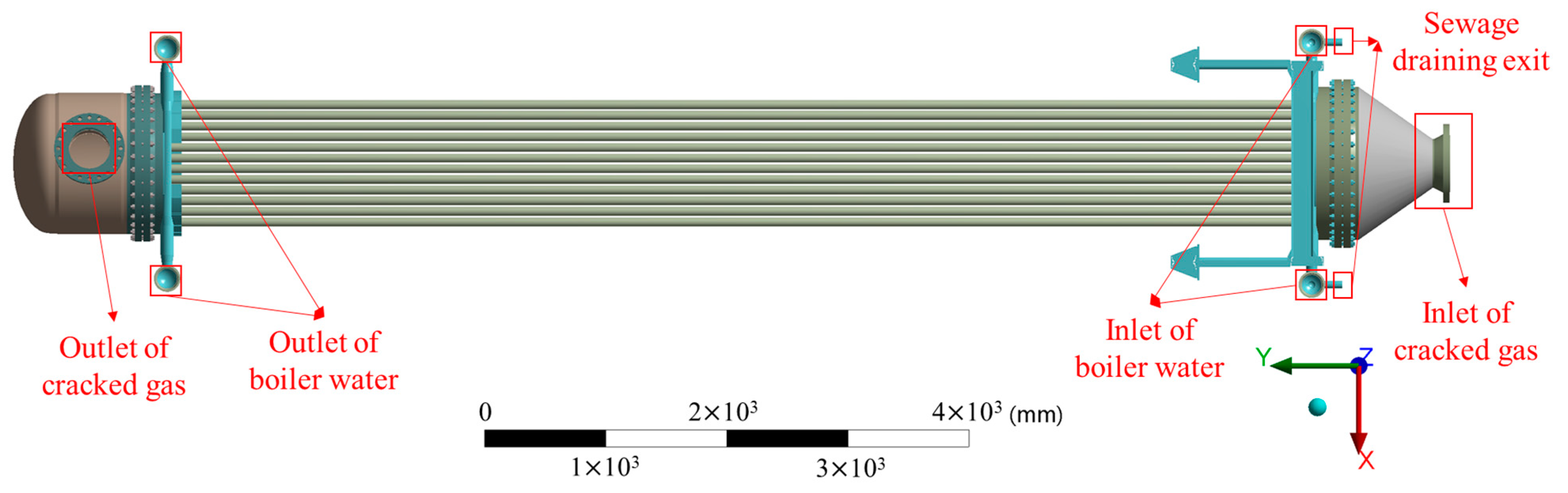
2.1. Geometric and Grid Models

In the investigated quench boiler, hot cracking gas enters heat exchange tubes with a length of 9500 mm through the intake cone of the lower part of the quench boiler, and the boiler water enters jacketed tubes with a length of 9378 mm through the collecting pipes on both sides of the flat-round tubesheet in the lower part of the quench boiler. There are 40 pairs of heat exchange tubes and jacketed tubes. At each end of the boiler, there is a special tubesheet formed by welding nine flat-round tubes side by side. The materials used and their properties are shown in Table 1. The whole geometric model of the quench boiler is shown in Figure 1. In this study, solid element Solid 185 was used with ANSYS to mesh the structure and perform structural analysis, and Solid 70 was applied to perform thermal analysis. In addition, a hexahedral grid was used for grid division, and the final model comprised approximately 12.53 million nodes and 9.71 million elements after a grid independence test. Figure 2a shows the grid model of the flat-round tubesheet and collector headers, and Figure 2b shows the grid model in the connection zone of the flat-round tubesheet, heat exchange tubes and jacketed tubes.

2.2. Loads and Constraints

Loads applied on the quench boiler include internal pressure, dead weight, tube load, bolt pretightening force, pretension of the heat exchange tubes and temperature load.
  • Internal pressures include a shell-side design pressure of 13.78 MPa/working pressure of 12.56 MPa and a pipe-side design pressure of 0.343 MPa/working pressure of 0.08 MPa;
  • Dead weight with a gravitational acceleration of 9.81 m/s2;
  • Equivalent tube load was calculated according to the following equation:
P o = P D i 2 D o 2 D i 2
where P is the internal pressure (MPa), Po is the equivalent tube load (MPa), Do is the outside diameter of the tube (mm) and Di is the inside diameter of the tube (mm). Data used to calculate equivalent tube loads are listed in Table 2.
  • Bolt pretightening force (F) was calculated according to the following equation:
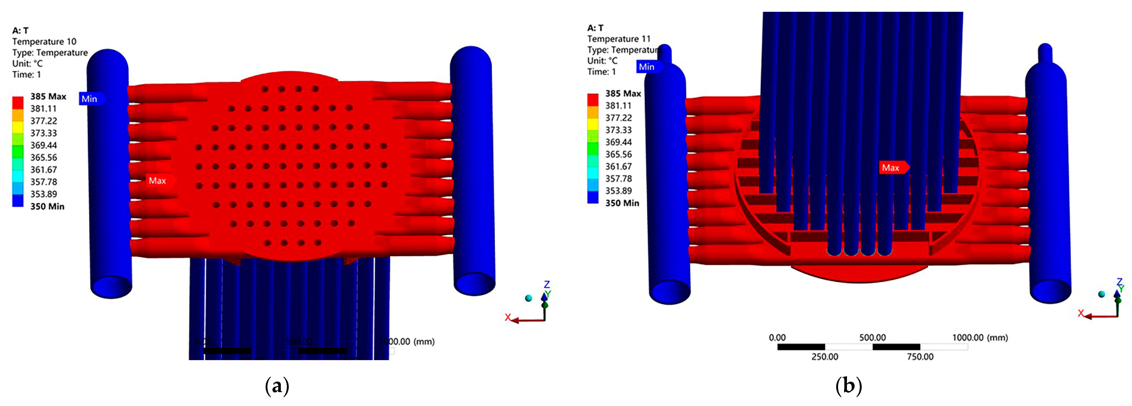
T = K F d
where T is the tightening torque (N·mm), F is the pretightening force (N), d is the thread nominal diameter (mm) and K is the tightening force coefficient (0.2). The data used to calculate the bolt pretightening force are listed in Table 3.
  • Thermal load
The design temperatures for other parts were numerically computed based on these given temperatures. Figure 3 shows the temperature distribution at the upper and lower ends of the quench boiler.
Based on the design temperature and the length and linear expansion coefficients of the heat exchange tubes and the jacketed tubes, the thermal expansion difference between these two tubes was calculated as:
δ = L i t i α i L o t o α o = 9500 × 385 × 14.23 9378 × 350 × 13.6 10 6 = 7.407   mm
where Li is the length of the heat exchange tubes (mm), where Li = 9500 mm; ti is the design temperature of the heat exchange tubes (°C) where ti = 385 °C; α i is the linear expansion coefficient of the heat exchange tubes (mm/mm·°C) where, α i = 14.23 × 106 mm/mm °C; Lo is the length of the jacketed tubes (mm), where Lo = 9378 mm; to is the design temperature of the jacketed tubes (°C), where to = 350 °C; α o is the linear expansion coefficient of the jacketed tubes (mm/mm·°C), where α o = 13.6 × 106 mm/mm °C; and δ is the thermal expansion difference between the heat exchange tubes and the jacketed tubes (mm).
With reference to the thermal expansion difference between the heat exchange tubes and the jacketed tubes, in this paper, we will study the influence of different pretensions (i.e., 5, 7, 9, 11 and 13 mm) of the heat exchange tubes in the flat-round tubesheet structure.
  • Constraints.
Without considering temperature, fixed constraints were applied on the lower surface of the four gasket plates in the quench boiler bracket. Considering temperature, the remote displacement constraints were applied on the lower surface of the four plates of the bracket to avoid excessive constraint on the thermal deformation.

2.3. Cases of Calculation

The pipe-side pressure in the quench boiler is relatively minimal and induces minimal stress on the flat-round tubesheet. However, the shell-side pressure is larger and more dangerous for the flat-round tubesheet. Therefore, in this paper, two dangerous load cases were considered, as listed in Table 4.

3. Results and Discussion

In this study, we focused on the effects of prestretching the heat exchange tubes on the stress distribution in a quench boiler, especially on the flat-round tubesheets. As the upper flat-round tubesheet and lower flat-round tubesheet of the quench boiler are generally symmetric to each other in terms of structure and loadings, only results for the upper flat-round tubesheet will be presented in the following sections.

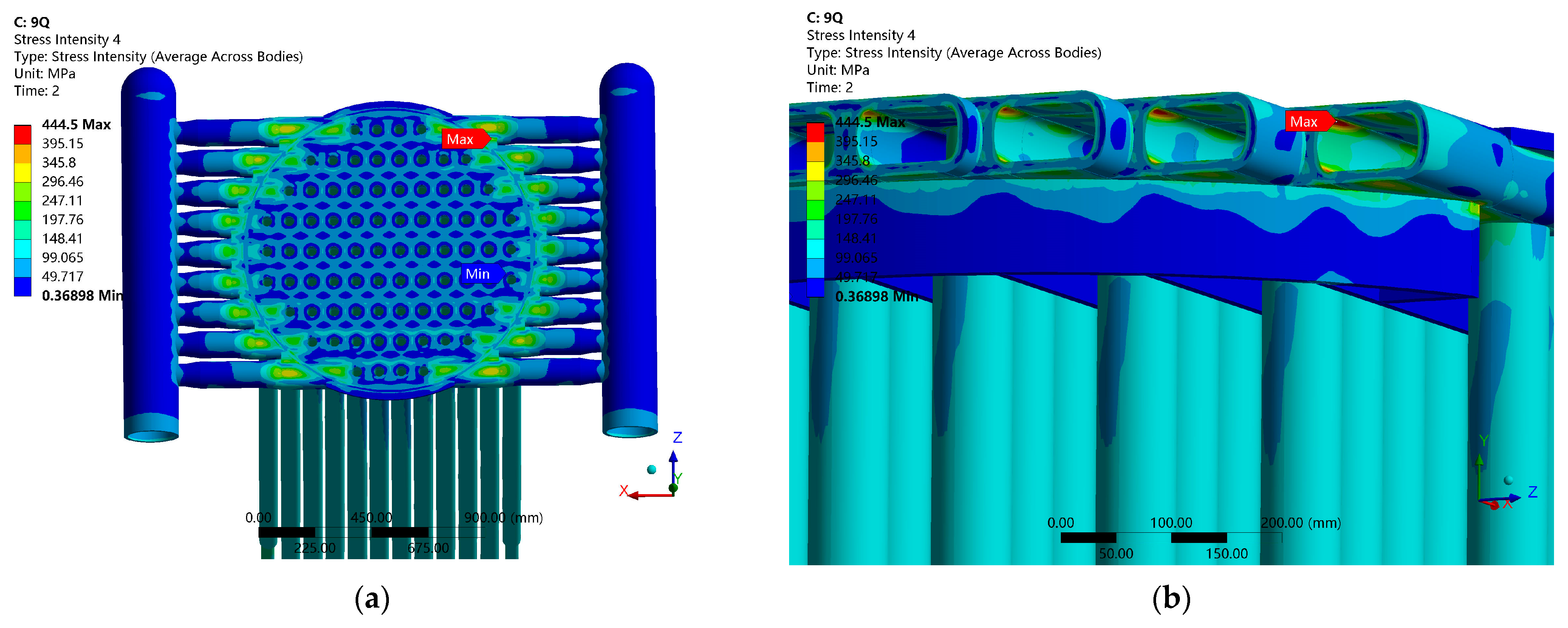
3.1. Stress Distribution on the Flat-Round Tubesheet without Prestretching the Heat Exchange Tubes

3.1.1. Load Case 1

Stress intensity distributions at the upper end of the quench boiler are shown in Figure 4 for the load case without prestretching of the heat exchange tubes. The maximum stress intensity at the upper end is 448.61 MPa, occurring in the peripheral arc area surrounding the non-tube layout zone on the flat-round tubesheet, as indicated by the red arrow in Figure 4. This phenomenon occurred because in the tube layout zone, both the inner heat exchange tubes and the jacketed tubes restrained the deformation of the flat-round tubesheet; in other words, the strength of the flat-round tubesheet was reinforced by the double tubes.

3.1.2. Load Case 2

Stress intensity distributions at the upper end of the quench boiler are shown in Figure 5 for the load case without prestretching of the heat exchange tubes. The maximum stress intensity at the upper end is 643.61 MPa, occurring in the peripheral arc area on the flat-round tubesheet surrounding the tube layout zone.

3.2. Stress Distribution on the Flat-Round Tubesheet with 9 mm Prestretching of the Heat Exchange Tubes

3.2.1. Load Case 1

The heat exchange tubes and the stress intensity distributions at the upper end of the quench boiler are shown in Figure 6 under the load case with 9 mm prestretching (i.e., pretension; rationale for 9 mm selection presented in Section 3.3.). In comparison with Figure 4, the stress one the flat-round tubesheets was improved. The maximum stress intensity at the upper end is 444.5 MPa.

3.2.2. Load Case 2

Stress intensity distributions at the upper end of the quench boiler are shown in Figure 7 under the load case with prestretching of the heat exchange tubes. Compared with Figure 5, the stress on the flat-round tubesheet was considerable improved, with the maximum stress intensity decreased to 418.44 MPa.

3.3. Determination of the Optimal Magnitude of Pretension

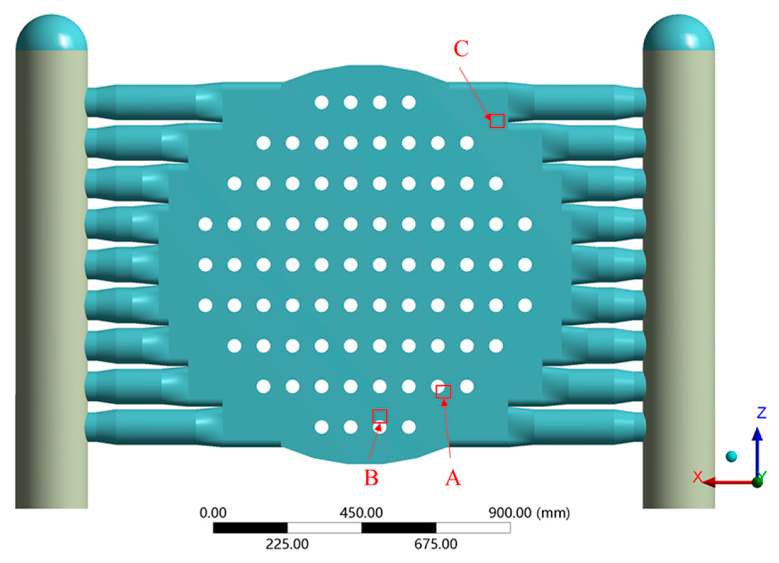
3.3.1. Strength Assessment

In order to obtain a suitable range of pretension of the heat transfer tubes, a strength assessment of the flat-round tubesheet should be conducted based relevant codes for the design of pressure vessels. In this study, Chinese code JB/4732-1995, Steel Pressure VesselsDesign by Analysis [23], was applied, which is similar to ASME VIII-2 in principle. Specifically, a strength assessment was performed using a stress classification method; to this end, strength assessment paths at dangerous positions must be defined for stress linearization. In this study, three dangerous parts on the flat-round tubesheet were specified, as shown in Figure 8: A was located at the connection between the flat-round tubesheet and the heat exchange tubes; B was located in the peripheral arc area surrounding the tube layout zone on the flat-round tubesheet; and C was located in the peripheral arc area surrounding the non-tube layout zone. As shown in Figure 9, three paths (A1-A2, B1-B2 and C1-C2) were set for the above three dangerous locations.
According to the stress strength assessment criteria in JB4732-1995, Steel Pressure Vessels–Design by Analysis, the flat-round tubesheet strength in the structural discontinuity area is assessed by following formulae.
P L 1.5 K S m
P L + P b + Q 3 K S m
where PL is the primary local membrane stress, Pb is the primary bending stress; Q is the secondary stress, PL + Pb + Q is the combined primary and secondary stress, Sm is the allowable stress at a given temperature (MPa) and K is the load factor. Based on the code, the stress limit of PL and the stress limit of PL + Pb + Q are shown in Table 5.

3.3.2. Load Case 1

Figure 10 shows the primary local membrane stress (PL’s) at the three paths, i.e., A1-A2, B1-B2 and C1-C2, which change with the magnitude of the pretension. The stress limit of 1.5 Sm or 170 MPa is also plotted. Under the given the magnitude of pretension, the primary local membrane stresses (PL’s) at the three paths are all lower than the stress limit, meaning that the primary local membrane stress meets the strength requirement. Figure 11a shows the PL + Pb + Q’s at the three paths, i.e., A1-A2, B1-B2 and C1-C2, which change with the magnitude of the pretension. The stress limit of 3Sm or 340 MPa is also plotted. Figure 11b shows a magnification of curve C and the limit line. Figure 10 shows that PL + Pb + Q at paths A1-A2 and B1-B2 pass the strength assessment for all given pretensions. However, if pretension is less than 9 mm, PL + Pb + Q at path C1-C2 cannot meet the strength requirement. Therefore, a pretension of 9 mm is the lowest acceptable value for the strength design of a quench boiler.

3.3.3. Load Case 2

Because the thermal stress belongs to the secondary stress, only PL + Pb + Q was evaluated under load case 2. The strength assessment results of the upper flat-round tubesheet are shown in Figure 12. Under pretensions of 5–13 mm, PL + Pb + Q values at all the three paths are lower than the stress limit, implying that the strength requirements for PL + Pb + Q are satisfied.
Based on the above results, strength requirement of the quench boiler is met, and prestretching of the heat exchange tubes is necessary, with an optimal pretension of 9 mm.

4. Conclusions

In this study, we investigated the effects of pretension of inner heat exchange tubes on the strength of the flat-round tubesheet of a quench boiler. Our main conclusions are as follow:
  • Under tube-side pressure with temperature loadings, the maximum stress was located in the peripheral arc area surrounding the tube layout zone. However, without temperature loadings, the maximum stress was located in the peripheral arc area surrounding the non-tube layout zone;
  • Without prestretching of the heat exchange tubes, the flat-round tubesheet cannot pass the strength assessment. Prestretching of the heat exchange tubes is necessary, with an optimal pretension of 9 mm;
  • Prestretching of the heat exchange tubes induces varied effects on the strength in different areas of the flat-round tubesheet. Appropriate pretension of the heat exchange tube can significantly reduce the stress in the tube layout zone, with little effect on the non-tube layout zone; and
  • The magnitude of pretension of the heat exchange tubes should be determined based on the thermal expansion difference between the inner heat exchange tubes and the jacketed tubes, with consideration the strength of the flat-round tubesheet.

Author Contributions

Writing—original draft, data curation, formal analysis, software, visualization, G.Z.; supervision, resources, methodology, funding acquisition, G.Q.; project administration, funding acquisition, B.L.; supervision, investigation, funding acquisition, F.X.; writing—review & editing, resources, formal analysis, C.Q. All authors have read and agreed to the published version of the manuscript.

Funding

This research received no external funding.

Data Availability Statement

Data available on request.

Conflicts of Interest

The authors declare no conflict of interest.

References

  1. Ren, T.; Patel, M.K. Basic petrochemicals from natural gas, coal and biomass: Energy use and CO2 emissions. Resour. Conserv. Recycl. 2009, 53, 513–528. [Google Scholar] [CrossRef]
  2. Wang, Z.; Han, Y.; Li, C.; Geng, Z.; Fan, J. Input-output networks considering graphlet-based analysis for production optimization: Application in ethylene plants. J. Clean. Prod. 2021, 278, 123955. [Google Scholar] [CrossRef]
  3. Ghanta, M.; Fahey, D.; Subramaniam, B. Environmental impacts of ethylene production from diverse feedstocks and energy sources. Appl. Petrochem. Res. 2014, 4, 167–179. [Google Scholar] [CrossRef] [Green Version]
  4. Li, P.; Li, T.; Cao, J. Advanced Process Control of an Ethylene Cracking Furnace. Meas. Control 2015, 48, 50–53. [Google Scholar] [CrossRef]
  5. Chen, J.; Yu, B.; Wei, Y. Energy technology roadmap for ethylene industry in China. Appl. Energy 2018, 224, 160–174. [Google Scholar] [CrossRef]
  6. Thiruvenkataswamy, P.; Eljack, F.; Roy, N.; Mannan, M.; El-Halwagi, M. Safety and techno-economic analysis of ethylene technologies. J. Loss Prev. Process Ind. 2016, 39, 74–84. [Google Scholar] [CrossRef] [Green Version]
  7. Haghighi, S.; Rahimpour, M.; Raeissi, S.; Dehghani, O. Investigation of ethylene production in naphtha thermal cracking plant in presence of steam and carbon dioxide. Chem. Eng. J. 2013, 228, 1158–1167. [Google Scholar] [CrossRef]
  8. Mynko, O.; Amghizar, I.; Brown, D.; Chen, L.; Marin, G. Reducing CO2 emissions of existing ethylene plants: Evaluation of different revamp strategies to reduce global CO2 emission by 100 million tonnes. J. Clean. Prod. 2022, 362, 132127. [Google Scholar] [CrossRef]
  9. Sadrameli, S. Thermal/catalytic cracking of hydrocarbons for the production of olefins: A state-of-the-art review I: Thermal cracking review. Fuel 2015, 140, 102–115. [Google Scholar] [CrossRef]
  10. Fahim, M.; Alsahhaf, T.; Elkilani, A. Thermal Cracking and Coking. In Fundamentals of Petroleum Refining, 6th ed.; Fahim, M., Alsahhaf, T., Elkilani, A., Eds.; Elsevier: Amsterdam, The Netherlands, 2010; pp. 123–152. [Google Scholar]
  11. Fakhroleslam, M.; Sadrameli, S. Thermal/catalytic cracking of hydrocarbons for the production of olefins; a state-of-the-art review III: Process modeling and simulation. Fuel 2019, 252, 553–566. [Google Scholar] [CrossRef]
  12. Wang, T.; Ye, Z.; Wang, X.; Li, Z.; Du, W. Improved distributed optimization algorithm and its application in energy saving of ethylene plant. Chem. Eng. Sci. 2022, 251, 117449. [Google Scholar] [CrossRef]
  13. Gong, S.; Shao, C.; Zhu, L. Energy efficiency enhancement of energy and materials for ethylene production based on two-stage coordinated optimization scheme. Energy 2021, 217, 119401. [Google Scholar] [CrossRef]
  14. Wang, W.; Hu, G.; Zeng, T. Characteristic and approach of manufacture of pre-stress heat exchanger. Mach. Des. Manuf. 2007, 6, 136–138. (In Chinese) [Google Scholar]
  15. Wang, A.; Lan, F.; Xu, K. Manufacture of double jacket quench boiler. Press. Vessel Technol. 2007, 24, 58–61. (In Chinese) [Google Scholar]
  16. Sang, Z.; Widera, G. Stress Analysis of Elliptical Tube Plates in Heat Exchangers. J. Press. Vessel Technol. 1987, 109, 310–314. [Google Scholar] [CrossRef]
  17. Qian, C.; Yu, H.; Yao, L. Finite Element Analysis and Experimental Investigation of Tubesheet Structure. J. Press. Vessel Technol. 2009, 131, 011206. [Google Scholar] [CrossRef]
  18. Li, G.; Zhao, J. Design by Finite Element Analysis on Tubesheet of Heat Exchanger with a Central Hole. In Proceedings of the ASME 2011 Pressure Vessels & Piping Division Conference, Baltimore, MD, USA, 17–21 July 2011; pp. 755–760. [Google Scholar] [CrossRef]
  19. Laskin, I.; Volfson, B. Numerical Analytic Approach to a Calculation of a Thermal Stress State of Shell and Tube Heat Exchangers. In Proceedings of the ASME 2013 Pressure Vessels & Piping Division Conference, Paris, France, 14–19 July 2013; pp. 14–18. [Google Scholar] [CrossRef]
  20. Wu, J.; Zheng, Z.; Li, Y.; Pang, J.; Ke, Z.; Zhang, N. Numerical research on thermal stress of steam cooler tube sheet mechanical structure. In Proceedings of the 2021 4th International Conference on Mechanical, Electrical and Material Application (MEMA 2021), Chongqing, China, 29–31 October 2021; p. 012013. [Google Scholar] [CrossRef]
  21. Gu, F.; Dong, J.; Zhang, W. Stress analysis of vertical jacket heat exchanger based on pre-tension and stress technique. Press. Vessel Technol. 2017, 34, 41–46. (In Chinese) [Google Scholar]
  22. Zhang, L.; Dong, J.; Cui, F.; Shi, W.; Liu, L. Simulation and test analysis of prestressed double tubesheet exchanger. Press. Vessel Technol. 2018, 35, 41–46. (In Chinese) [Google Scholar]
  23. JB4732-1995; Steel Pressure Vessels—Design by Analysis. National Standard of the People’s Republic of China: Beijing, China, 1995.
Figure 1. Whole geometric model of the quench boiler.
Chemengineering 06 00075 g001
Figure 2. (a) Grid model of the flat-round tubesheet and collector headers. (b) Grid model of the connection zone of the flat-round tubesheet, heat exchange tubes and jacketed tubes.
Chemengineering 06 00075 g002
Figure 3. (a) Temperature distribution in the upper flat-round tubesheet. (b) Temperature distribution in the lower flat-round tubesheet.
Chemengineering 06 00075 g003
Figure 4. (a) Stress intensity distribution and (b) maximum stress on the upper flat-round tubesheet under load case 1 without prestretching of the tubes.
Chemengineering 06 00075 g004
Figure 5. (a) Stress intensity distribution and (b) maximum stress on the upper flat-round tubesheet under load case 2 without prestretching of the tubes.
Chemengineering 06 00075 g005
Figure 6. (a) Stress intensity distribution and (b) maximum stress on the upper flat-round tubesheet under load case 1 with 9 mm pretension of tubes.
Chemengineering 06 00075 g006
Figure 7. (a) Stress intensity distribution and (b) maximum stress on the upper flat-round tubesheet under load case 2 with 9 mm pretension of the tubes.
Chemengineering 06 00075 g007
Figure 8. Three dangerous parts at the flat-round tubesheet.
Chemengineering 06 00075 g008
Figure 9. Paths for stress linearization on the flat-round tubesheet.
Chemengineering 06 00075 g009
Figure 10. PL assessment at positions A, B and C under load case 1 with varying pretensions.
Chemengineering 06 00075 g010
Figure 11. PL + Pb + Q assessment under load case 1 with varying pretensions. (a) At positions A, B and C. (b) Magnification at position C.
Chemengineering 06 00075 g011
Figure 12. PL + Pb + Q assessment at positions A, B and C under load case 2 with varying pretensions.
Chemengineering 06 00075 g012
Table 1. Materials and properties of the quench boiler.
MaterialDesign Temperature
(°C)
Thermal Conductivity (W·(m·°C)−1)Young’s Modulus
(×103 MPa)
Linear Expansion Coefficient
(×10−6 mm/mm °C)
Poisson’s Ratio
16Mo338541.5818414.230.3
SA 106-Gr.B3504717913.60.3
12Cr2Mo136737.818713.360.3
45036.418013.930.3
13CrMo4-536738.8218513.790.3
45037.0317814.720.3
Q345R20048.619112.250.3
38542.9517213.480.3
Table 2. Data used to calculate equivalent tube loads.
LocationP (MPa)Do (mm)Di (mm)Po (MPa)
Inlet and outlet of boiler water13.78/12.5621918635.67/32.51
Cracked gas inlet0.343/0.084703800.65/0.15
Cracked gas outlet0.343/0.08412.83410.74/0.17
Sewage drainage exit13.78/12.5660.345.718.6/16.95
Table 3. Data used to calculate the bolt pretightening force.
LocationT (N·mm)d (mm)KF [N]
Upper flange joint175,000240.236,458
Lower flange joint195,000240.240,625
Table 4. Investigated load cases.
CaseShell-Side Pressure
(MPa)
Tube-Side Pressure
(MPa)
Thermal Deformation
113.780No
212.560Yes
Table 5. Stress intensity evaluation parameters.
PathSm (MPa)KStress Limit of PL (Mpa)Stress Limit of PL + Pb + Q (Mpa)
A1-A2, B1-B2, C1-C2113.331170340
Publisher’s Note: MDPI stays neutral with regard to jurisdictional claims in published maps and institutional affiliations.

