
Review of Current Collector-, Binder-, Conductive Additive-Free, and Freestanding Electrodes in Lithium and Related Batteries


Abstract
:1. Introduction
2. The Role of Current Collectors, Binders, and Conductive Additives in Present Batteries
2.1. Current Collector
2.2. Binder
2.3. Conductive Additives
3. Current Collector-Free Electrodes
3.1. Metal-Free Current Collector
3.2. Current Collector-Free Electrodes (Freestanding Electrodes)
4. Binder-Free Electrodes
4.1. Direct Growth of Active Materials on Current Collectors
4.2. Retention of Active Materials in a Conductive Three-Dimensional Matrix
4.3. Formation of EAM Layer Using Interactions
4.4. Three-Dimensional Structure of Active Materials
5. Conductive Additive-Free Electrodes
6. Comparison of Si Anode Performance
6.1. Current Collector-Free Si Anodes
6.2. Binder-Free Si Anodes
6.3. Conductive Additive-Free Si Anodes
6.4. Comprehensive Performance Comparison
7. Comparison of the Toughness of the Electrodes
8. Conclusions
- (1)
- In the current situation where there is a demand for improved energy density, one of the factors that must be addressed is the development of batteries that do not add collectors, binders, or conductive additives that cannot store energy.
- (2)
- The electrodes to be produced must not experience any degradation in performance compared to conventional batteries and must ensure long-term stability of performance and safety.
- (3)
- The functions of the CCs, BDs, and CAs are complementary to each other, so if one is removed from the electrode, the design must be such that the others take over its role.
- (4)
- To ensure electrode performance, it is important to select the structure of the electrode active material layer and the chemical substances that make it up, taking into consideration securing an electron transmission path with high electronic conductivity and a lithium-ion migration path, as well as stability over the long term and against electrochemical reactions.
Author Contributions
Funding
Data Availability Statement
Conflicts of Interest
Abbreviation
| AFSISD | Aqueous flexible sodium ion storage device |
| BD | Binder |
| BLTO | Beaded stream-like LTO |
| CA | Conductive additive |
| CB | Carbon black |
| CC | Current collector |
| CF | Carbon fiber |
| CF-CNT-P | Polymer (P)-based CF/CNT composite |
| CMC | Carboxymethyl cellulose |
| CNF | Cellulose nanofiber |
| CNFI | Carbon nanofiber |
| CNT | Carbon nanotube |
| CNTF | CNT fiber |
| CT | Charge-transfer |
| CVD | Chemical vapor deposition |
| EAM | Electrode active material |
| GO | Graphene oxide |
| IO | Inverse opal |
| LFP | Lithium iron phosphate |
| LiTFSI | Lithium bis(trifluoromethanesulfonyl)imide |
| LM | Liquid metal |
| LTO | Lithium titanate oxide |
| MAO | Microarc oxidation |
| MOF | Metal-organic framework |
| MWCNT | Multiwalled carbon nanotube |
| NCNF | N-doped carbon nanofiber |
| PAN | Polyacrylonitrile |
| PCL | Polycaprolactone |
| PDI | Perylene diimide |
| PLA | Polylactic acid |
| PMMA | Poly(methyl methacrylate) |
| PS | Polystyrene |
| PTCDI | Perylene tetracarboxylic diimide |
| PVDF | Polyvinylidene difluoride |
| PVdF-HFP | Poly(vinylidene fluoride-co-hexafluoropropylene) |
| PVP | Polyvinylpyrrolidone |
| Pyr14-TFSI | 1-butyl-1-methylpyrrolidinium bis-(trifluoromethanesulfonyl)imide |
| RGO | Reduced graphene oxide |
| SBR | Styrene–butadiene rubber |
| SNT | Silicon oxide nanotubes |
| TCNQ | Tetracyanoquinodimethane |
| TTF | Tetrathiafulvalene |
| VGCF | Vapor-grown carbon fiber |
References
- Winter, M.; Barnett, B.; Xu, K. Before Li ion batteries. Chem. Rev. 2018, 118, 11433–11456. [Google Scholar] [CrossRef] [PubMed]
- Zubi, G.; Dufo-López, R.; Carvalho, M.; Pasaoglu, G. The lithium-ion battery: State of the art and future perspectives. Renew. Sust. Energ. Rev. 2018, 89, 292–308. [Google Scholar] [CrossRef]
- Peters, J.F.; Baumann, M.; Zimmermann, B.; Braun, J.; Weil, M. The environmental impact of Li-Ion batteries and the role of key parameters—A review. Renew. Sust. Energ. Rev. 2017, 67, 491–506. [Google Scholar] [CrossRef]
- Liang, Y.; Zhao, C.-Z.; Yuan, H.; Chen, Y.; Zhang, W.; Huang, J.-Q.; Yu, D.; Liu, Y.; Titirici, M.-M.; Chueh, Y.-L.; et al. A review of rechargeable batteries for portable electronic devices. InfoMat 2019, 1, 6–32. [Google Scholar] [CrossRef]
- Deng, D. Li-ion batteries: Basics, progress, and challenges. Energy Sci. Eng. 2015, 3, 385–418. [Google Scholar] [CrossRef]
- Walter, M.; Kovalenko, M.V.; Kravchyk, K.V. Challenges and benefits of post-lithium-ion batteries. New J. Chem. 2020, 44, 1677. [Google Scholar] [CrossRef]
- Wu, B.; Chen, C.; Danilov, D.L.; Eichel, R.A.; Notten, P.H.L. All-solid-state thin film Li-ion batteries: New challenges, new materials, and new designs. Batteries 2023, 9, 186. [Google Scholar] [CrossRef]
- Li, M.; Lu, J.; Chen, Z.; Amine, K. 30 years of lithium-ion batteries. Adv. Mater. 2018, 30, 1800561. [Google Scholar] [CrossRef]
- Watanabe, T.; Tsuda, T.; Ando, N.; Nakamura, S.; Hayashi, N.; Soma, N.; Gunji, T.; Ohsaka, T.; Matsumoto, F. An improved pre-lithiation of graphite anodes using through-holed cathode and anode electrodes in a laminated lithium ion battery. Electrochim. Acta 2019, 324, 13484. [Google Scholar] [CrossRef]
- Lee, H.; Choi, W.; Park, H.S.; Kim, D.W. Realization of high loading density lithium polymer batteries by optimizing lithium-ion transport and electronic conductivity. ACS Appl. Mater. Interfaces. 2023, 15, 15298–15310. [Google Scholar] [CrossRef]
- Tsuda, T.; Ando, N.; Nakamura, S.; Ishihara, Y.; Hayashi, N.; Soma, N.; Gunji, T.; Tanabe, T.; Ohsaka, T.; Matsumoto, F. Improvement of high-rate discharging performance of LiFePO4 cathodes by forming micrometer-sized through-holed electrode structures with a pico-second pulsed laser. Electrochim. Acta 2019, 296, 27–38. [Google Scholar] [CrossRef]
- Bree, G.; Horstman, D.; Low, C.T.J. Light-weighting of battery casing for lithium-ion device energy density improvement. J. Energy Storage. 2023, 68, 107852. [Google Scholar] [CrossRef]
- Yamada, M.; Watanabe, T.; Gunji, T.; Wu, J.; Matsumoto, F. Review of the design of current collectors for improving the battery performance in lithium-ion and post-lithium-ion batteries. Electrochem 2020, 2, 124–159. [Google Scholar] [CrossRef]
- Zhang, L.; Qin, X.; Zhao, S.; Wang, A.; Luo, J.; Wang, Z.L.; Kang, F.; Lin, Z.; Li, B. Advanced matrixes for binder-free nanostructured electrodes in lithium-ion batteries. Adv. Mater. 2020, 32, 1908445. [Google Scholar] [CrossRef] [PubMed]
- Xu, Y.; Zhou, M.; Lei, Y. Nanoarchitectured array electrodes for rechargeable lithium- and sodium-ion batteries. Adv. Energy Mater. 2016, 6, 1502514. [Google Scholar] [CrossRef]
- Delaporte, N.; Ossonon, D.B.; Zaghib, K.; Bélanger, D. Fabrication of current collectors and binder-free electrodes on separators used in lithium-ion batteries. Batter. Supercaps 2020, 3, 638–646. [Google Scholar] [CrossRef]
- Hu, X.; Jin, Y.; Zhu, B.; Tan, Y.; Zhang, S.; Zong, L.; Lu, Z.; Zhu, J. Free-standing graphene-encapsulated silicon nanoparticle aerogel as an anode for lithium ion batteries. ChemNanoMat 2016, 2, 671–674. [Google Scholar] [CrossRef]
- Dçrr, T.S.; Fleischmann, S.; Zeiger, M.; Grobelsek, I.; de Oliveira, P.W.; Presser, V. Ordered mesoporous titania/carbon hybrid monoliths for lithium-ion battery anodes with high areal and volumetric capacity. Chem. Eur. J. 2018, 24, 6358–6363. [Google Scholar] [CrossRef]
- Whitehead, A.H.; Schreiber, M. Current collectors for positive electrodes of lithium-based batteries. J. Electrochem. Soc. 2005, 52, A2105–A2113. [Google Scholar] [CrossRef]
- Zhu, P.; Gastol, D.; Marshall, J.; Sommerville, R.; Goodship, V.; Kendrick, E. A review of current collectors for lithium-ion batteries. J. Power Sources 2021, 485, 229321. [Google Scholar] [CrossRef]
- Li, H.; Wang, L.; Song, Y.; Zhang, Z.; Zhang, H.; Du, A.; He, X. Significance of current collectors for high performance conventional lithium-ion batteries: A review. Adv. Funct. Mater. 2023, 33, 2305515. [Google Scholar] [CrossRef]
- Kataoka, R.; Oda, Y.; Inoue, R.; Kitta, M.; Kiyobayashi, T. High-strength clad current collector for silicon-based negative electrode in lithium ion battery. J. Power Sources 2016, 301, 355–361. [Google Scholar] [CrossRef]
- Myunga, S.-T.; Sasaki, Y.; Sakurada, S.; Sun, Y.-K.; Yashiro, H. Electrochemical behavior of current collectors for lithium batteries in non-aqueous alkyl carbonate solution and surface analysis by ToF-SIMS. Electrochim. Acta 2009, 55, 288–297. [Google Scholar] [CrossRef]
- Yao, Y.; Jiang, F.; Yang, C.; Fu, K.K.; Hayden, J.; Lin, C.-F.; Xie, H.; Jiao, M.; Yang, C.; Wang, Y.; et al. Epitaxial welding of carbon nanotube networks for aqueous battery current collectors. ACS Nano 2018, 12, 5266–5273. [Google Scholar] [CrossRef] [PubMed]
- Luo, W.; Hayden, J.; Jang, S.-H.; Wang, Y.; Zhang, Y.; Kuang, Y.; Wang, Y.; Zhou, Y.; Rubloff, G.W.; Lin, C.-F.; et al. Highly conductive, light weight, robust, corrosion resistant, scalable, all-fiber based current collectors for aqueous acidic batteries. Adv. Energy Mater. 2018, 8, 1702615. [Google Scholar] [CrossRef]
- Wang, M.; Le, A.V.; Shi, Y.; Noelle, D.J.; Qiao, Y. Heterogeneous current collector in lithium-ion battery for thermal-runaway mitigation. Appl. Phys. Lett. 2017, 110, 083902. [Google Scholar] [CrossRef]
- Ma, Y.; Ma, J.; Cui, G. Small things make big deal: Powerful binders of lithium batteries and post-lithium batteries. Energy Stor. Mater. 2019, 20, 146–175. [Google Scholar] [CrossRef]
- Costa, C.M.; Cardoso, V.F.; Martins, P.; Correia, D.M.; Gonçalves, R.; Costa, P.; Correia, V.; Ribeiro, C.; Fernandes, M.M.; Martins, P.M.; et al. Smart and multifunctional materials based on electroactive poly(vinylidene fluoride): Recent advances and opportunities in sensors, actuators, energy, environmental, and biomedical applications. Chem. Rev. 2023, 123, 11392–11487. [Google Scholar] [CrossRef]
- Buq, H.; Holzapfel, M.; Krumeich, F.; Veit, D.; Novák, P. Study of styrene butadiene rubber and sodium methyl cellulose as binder for negative electrodes in lithium-ion batteries. J. Power Sources 2006, 161, 617–622. [Google Scholar] [CrossRef]
- Zheng, H.; Yang, R.; Liu, G.; Song, X.; Battaglia, V.S. Cooperation between active material, polymeric binder and conductive carbon additive in lithium ion battery cathode. J. Phys. Chem. C 2012, 116, 4875–4882. [Google Scholar] [CrossRef]
- Zhang, L.; Wu, X.; Qian, W.; Pan, K.; Zhang, X.; Li, L.; Jia, M.; Zhang, S. Exploring more functions in binders for lithium batteries. Electrochem. Energy Rev. 2023, 6, 36. [Google Scholar] [CrossRef]
- Chen, B.; Zhang, Z.; Meng, Y.; Xiao, M. Polymeric binders used in lithium ion batteries: Actualities, strategies and trends. ChemElectroChem 2024, 11, e202300651. [Google Scholar] [CrossRef]
- Chou, S.-L.; Pan, Y.; Wang, J.-Z.; Liu, H.-K.; Dou, S.-X. Small things make a big difference: Binder effects on the performance of Li and Na batteries. Phys. Chem. Chem. Phys. 2014, 16, 20347–20359. [Google Scholar] [CrossRef] [PubMed]
- Dobryden, I.; Montanari, C.; Bhattacharjya, D.; Aydin, J.; Ahniyaz, A. Bio-based binder development for lithium-ion batteries. Materials 2023, 16, 5553. [Google Scholar] [CrossRef] [PubMed]
- Choi, S.; Kwon, T.-W.; Coskun, A.; Choi, J.W. Highly elastic binders integrating polyrotaxanes for silicon microparticle anodes in lithium ion batteries. Science 2017, 357, 279–283. [Google Scholar] [CrossRef] [PubMed]
- Li, J.-T.; Wu, Z.-Y.; Lu, Y.-Q.; Zhou, Y.; Huang, Q.-S.; Huang, L.; Sun, S.-G. Water soluble binder, an electrochemical performance booster for electrode materials with high energy density. Adv. Energy Mater. 2017, 7, 1701185. [Google Scholar] [CrossRef]
- Spahr, M.E.; Goers, D.; Leone, A.; Stallone, S.; Grivei, E. Development of carbon conductive additives for advanced lithium ion batteries. J. Power Sources 2011, 196, 3404–3413. [Google Scholar] [CrossRef]
- Shi, Y.; Wen, L.; Pei, S.; Wu, M.; Li, F. Choice for graphene as conductive additive for cathode of lithium-ion batteries. J. Energy Chem. 2019, 30, 19–26. [Google Scholar] [CrossRef]
- Kubarkov, A.V.; Babkin, A.V.; Drozhzhin, O.A.; Stevenson, K.J.; Antipov, E.V.; Sergeyev, V.G. Engendering high energy density LiFePO4 electrodes with morphological and compositional tuning. Nanomaterials 2023, 13, 1771. [Google Scholar] [CrossRef]
- Yap, J.W.; Wang, T.; Cho, H.; Kim, J.-H. Comparison of carbon-nanofiber and carbon-nanotube as conductive additives in Si anodes for high-energy lithium-ion batterie. Electrochim. Acta 2023, 446, 142108. [Google Scholar] [CrossRef]
- Entwistle, J.; Ge, R.; Pardikar, K.; Smith, R.; Cumming, D. Carbon binder domain networks and electrical conductivity in lithium-ion battery electrodes: A critical review. Renew. Sust. Energ. Rev. 2022, 166, 112624. [Google Scholar] [CrossRef]
- Lauro, S.N.; Broekhuis, B.G.; Papa, P.E.; Rastogi, A.; Burrow, J.N.; Ellison, C.J.; Mullins, C.B. A balancing act: Experimental insights into the volume fraction of conductive additive in lithium-ion battery electrodes. J. Electrochem. Soc. 2024, 171, 060525. [Google Scholar] [CrossRef]
- Baumgärtner, J.F.; Kravchyk, K.V.; Kovalenko, M.V. Navigating the carbon maze: A roadmap to effective carbon conductive networks for lithium-ion batteries. Adv. Energy Mater. 2024, 2400499. [Google Scholar] [CrossRef]
- Islam, J.; Chowdhury, F.I.; Uddin, J.; Amin, R.; Uddin, J. Review on carbonaceous materials and metal composites in deformable electrodes for flexible lithium-ion batteries. RSC Adv. 2021, 11, 5958–5992. [Google Scholar] [CrossRef] [PubMed]
- Zhang, J.; Cheng, W.; Zhang, R.; Zeng, T.; Lei, Y.; Zhao, H.; Luo, D. Investigation of carbon fiber anode materials for collector-free lithium-ion batteries. Int. J. Low Carbon Technol. 2022, 17, 1216–1222. [Google Scholar] [CrossRef]
- Ha, S.H.; Jeong, Y.S.; Lee, Y.J. Free standing reduced graphene oxide film cathodes for lithium ion batteries. ACS Appl. Mater. Interfaces 2013, 5, 12295–12303. [Google Scholar] [CrossRef]
- Rana, K.; Singh, J.; Lee, J.-T.; Park, J.H.; Ahn, J.-H. Highly conductive freestanding graphene films as anode current collectors for flexible lithium-ion batteries. ACS Appl. Mater. Interfaces 2014, 6, 11158–11166. [Google Scholar] [CrossRef]
- Fritsch, M.; Coeler, M.; Kunz, K.; Krause, B.; Marcinkowski, P.; Pötschke, P.; Wolter, M.; Michaelis, A. Lightweight polymer-carbon composite current collector for lithium-ion batteries. Batteries 2020, 6, 60. [Google Scholar] [CrossRef]
- Moyer, K.; Boucherbil, N.A.; Zohair, M.; Eaves-Rathert, J.; Pint, C.L. Polymer reinforced carbon fiber interfaces for high energy density structural lithium-ion batteries. Sustain. Energy Fuels 2020, 4, 2661–2668. [Google Scholar] [CrossRef]
- Sharma, J.; Demchuk, Z.; Polizos, G.; Kanbargi, N.; Tao, R.; Naskar, A.; Li, J. Aligned carbon fibers-carbon nanotube-polymer-based composite as lithium-ion battery current collector. J. Mater. Process Technol. 2023, 318, 118015. [Google Scholar] [CrossRef]
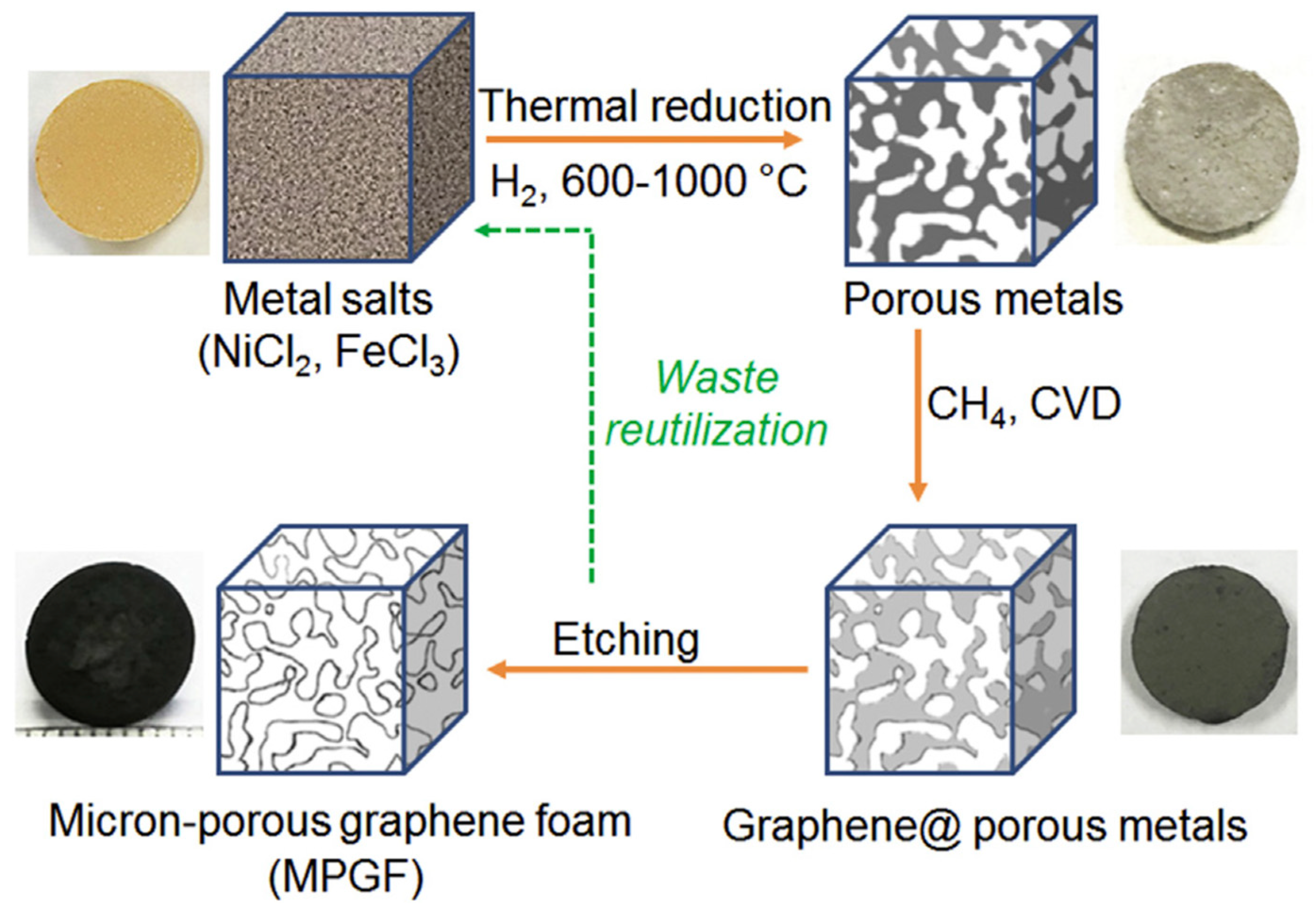
- Lu, L.; De Hosson, J.T.M.; Pei, Y. Three-dimensional micron-porous graphene foams for lightweight current collectors of lithium-sulfur batteries. Carbon 2019, 144, 713–723. [Google Scholar] [CrossRef]
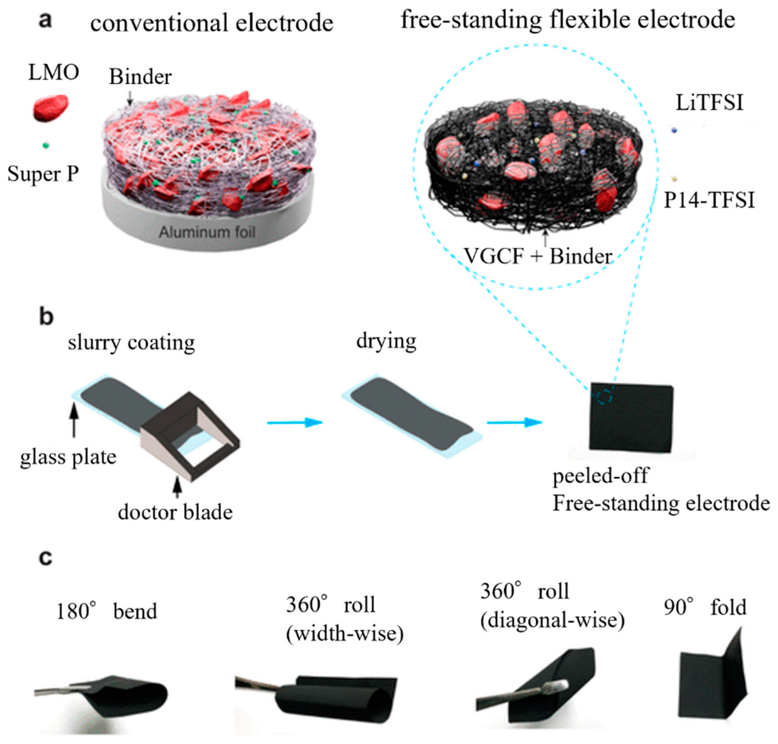
- Phiri, I.; Kim, J.; Mpupuni, C.T.; Ssendagire, K.; Kim, J.-T.; Lee, Y.; Ryou, S.-Y. Keeping it simple: Free-standing, flexible cathodic electrodes for high rate, long cycling lithium batteries. ACS Appl. Energy Mater. 2022, 5, 13535–13543. [Google Scholar] [CrossRef]
- Zhao, P.; Li, W.; Fang, S.; Yu, J.; Yang, Z.; Cai, J. Cut-price fabrication of free-standing porous carbon nanofibers film electrode for lithium-ion batteries. Appl. Sci. 2019, 9, 1016. [Google Scholar] [CrossRef]
- Liang, S.; Pei, X.; Jiang, W.; Xu, Z.; Wang, W.; Teng, K.; Wang, C.; Fu, H.; Zhang, X. Free-standing dual-network red phosphorus@porous multichannel carbon nanofibers/carbon nanotubes as a stable anode for lithium-ion batteries. Electrochim. Acta 2019, 322, 134696. [Google Scholar] [CrossRef]
- Xiao, J.; Jin, Q.; Cang, R.; Gao, H.; Yao, J. Carbon-coated MXene nanofiber as a free-standing electrode for high-performance lithium-ion storage. Electrochim. Acta 2023, 451, 142289. [Google Scholar] [CrossRef]
- Cherian, S.K.; Kishore, K.R.; Reddy, S.; Sharma, C.S. Candle soot-embedded electrospun carbon nanofibers as a flexible and free-standing sulfur host for high-performance lithium−sulfur batteries. ACS Appl. Nano Mater. 2023, 6, 15574–15587. [Google Scholar] [CrossRef]
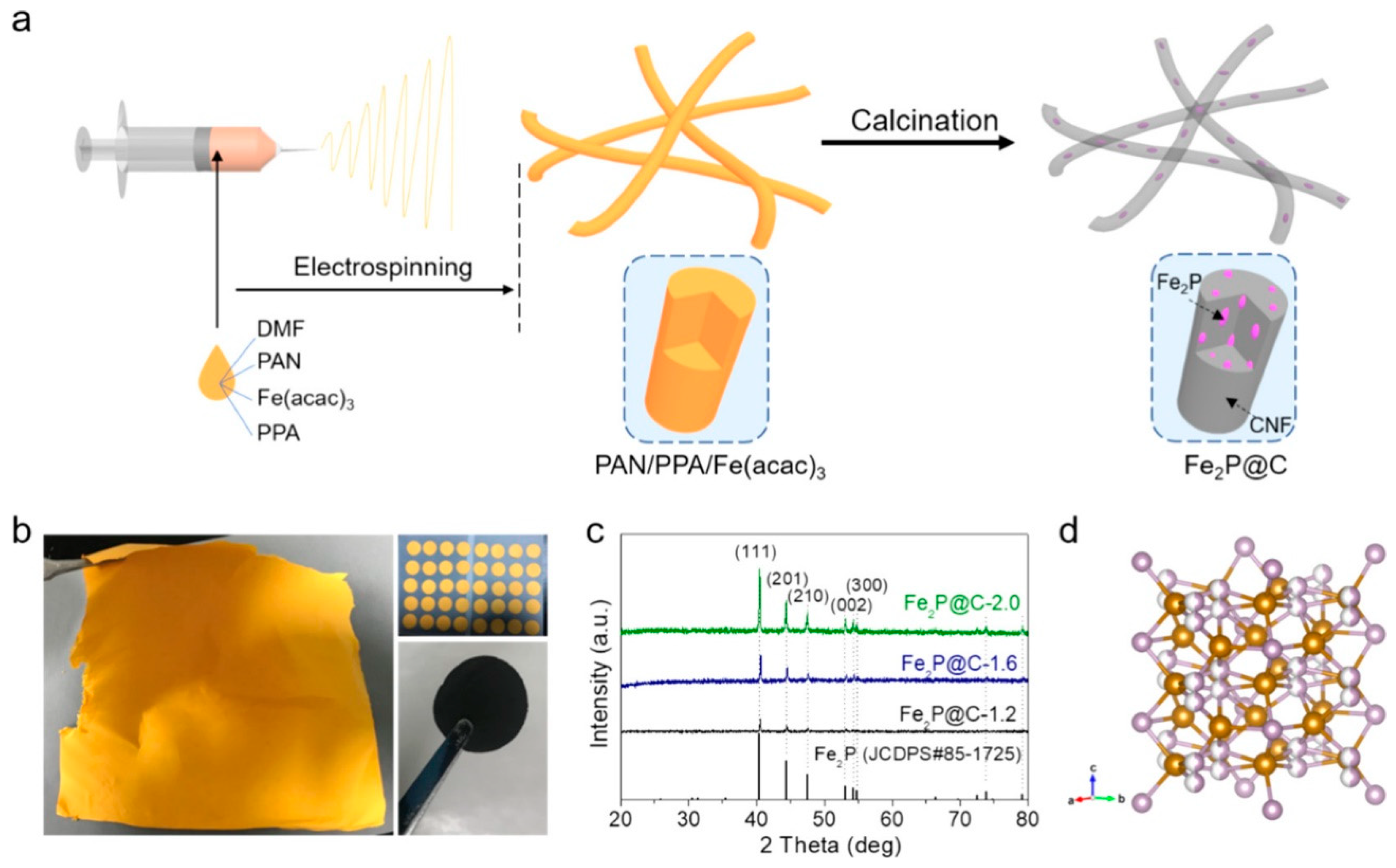
- Yang, Y.; Fu, W.; Bell, C.; Lee, D.-C.; Drexler, M.; Nuli, Y.; Ma, Z.-F.; Magasinski, A.; Yushin, G.; Alamgir, F.M. Iron phosphide confined in carbon nanofibers as a free-standing flexible anode for high-performance lithium-ion batteries. ACS Appl. Mater. Interfaces 2021, 13, 34074–34083. [Google Scholar] [CrossRef]
- Huang, J.; Wang, X.; Liu, J.; Sun, X.; Wang, L.; He, X. Flexible free-standing VO2(B) nanobelt films as additive-free cathode for lithium-ion batteries. Int. J. Electrochem. Sci. 2011, 6, 1709–1719. [Google Scholar] [CrossRef]
- Wang, J.; Wang, G.; Wang, H. Flexible free-standing Fe2O3/graphene/carbon nanotubes hybrid films as anode materials for high performance lithium-ion batteries. Electrochim. Acta 2015, 182, 192–201. [Google Scholar] [CrossRef]
- Zhao, S.; Li, M.; Wu, X.; Yu, S.H.; Zhang, W.; Luo, J.; Wang, J.; Geng, Y.; Gou, Q.; Sun, K. Graphene-based free-standing bendable films: Designs, fabrications, and applications. Mater. Today Adv. 2020, 6, 100060. [Google Scholar] [CrossRef]
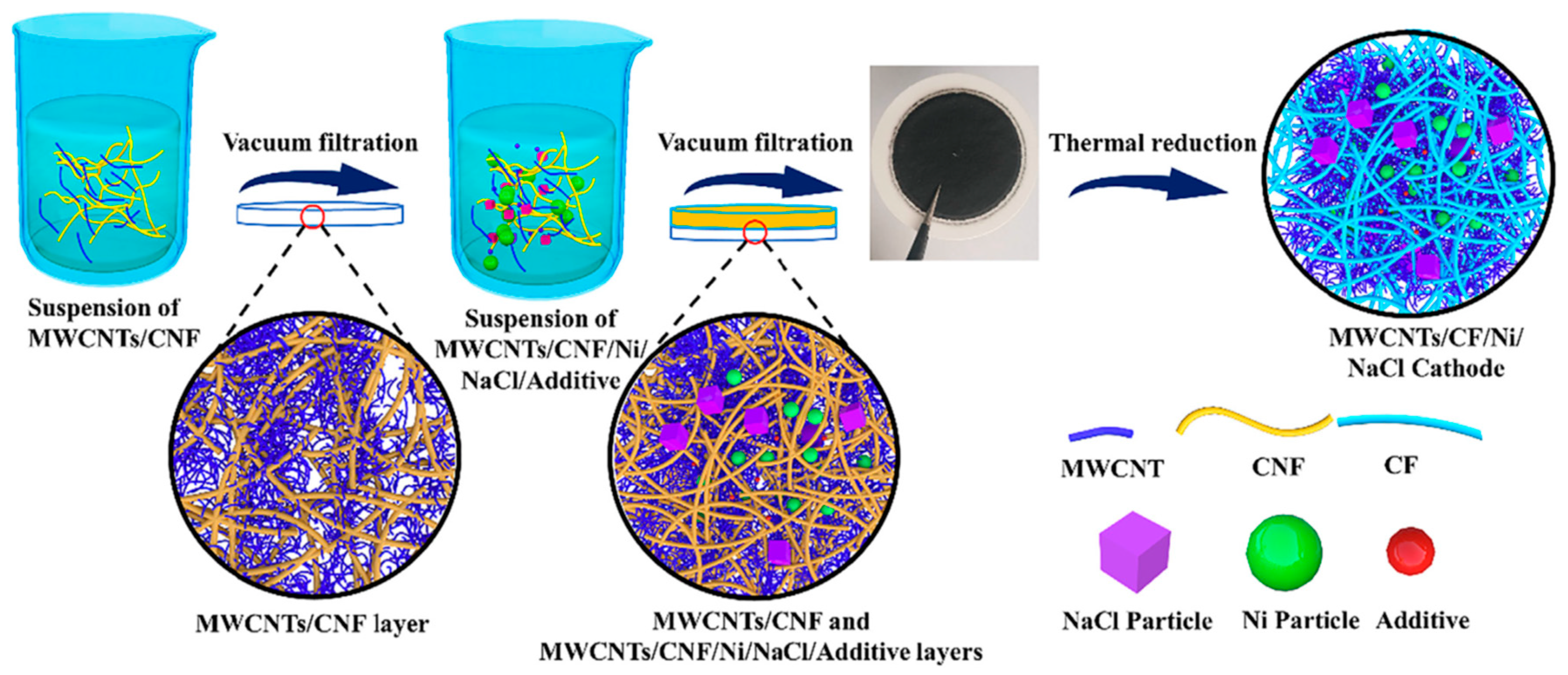
- Li, Y.; Wu, X.; Wang, J.; Gao, X.; Hu, Y.; Wen, Z. Ni-less cathode with 3D free-standing conductive network for planar Na-NiCl2 batteries. Chem. Eng. J. 2020, 387, 124059. [Google Scholar] [CrossRef]
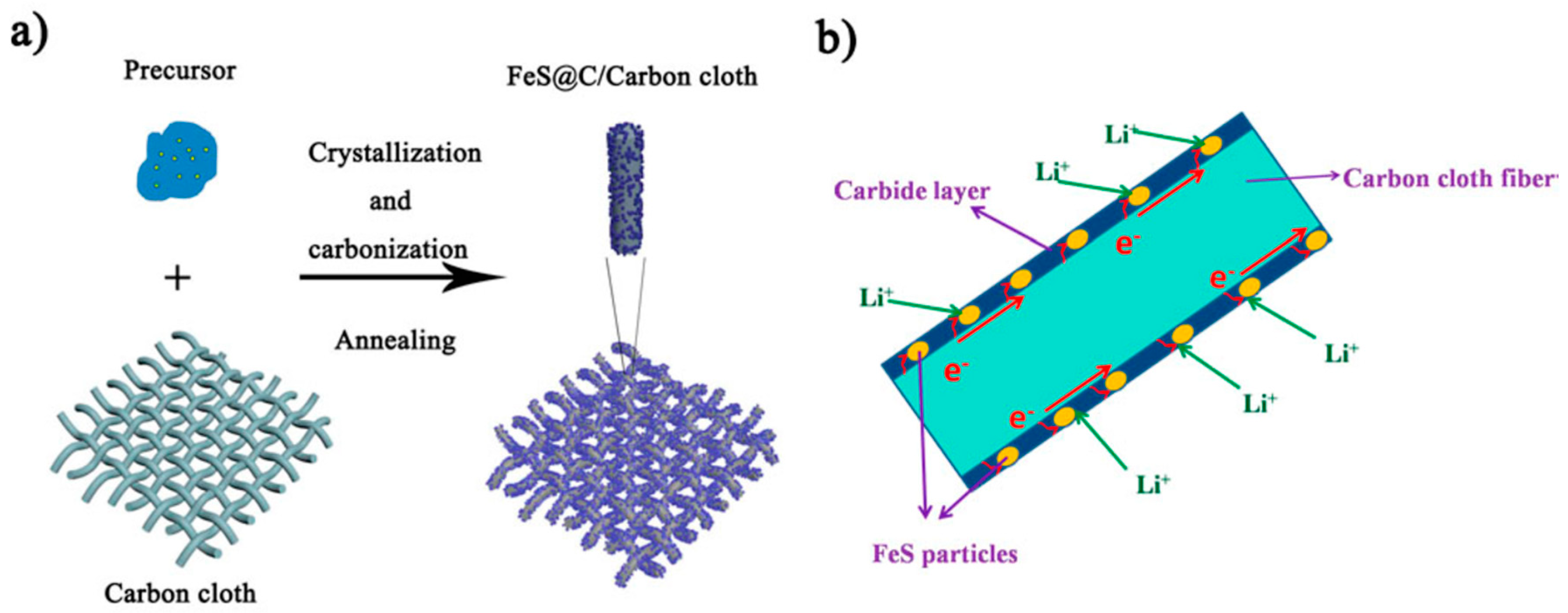
- Wei, X.; Li, W.; Shi, J.-a.; Gu, L.; Yu, Y. FeS@C on carbon cloth as flexible electrode for both lithium and sodium storage, ACS Appl. Mater. Interfaces 2015, 7, 27804–27809. [Google Scholar] [CrossRef] [PubMed]
- Sun, M.; Xie, Q.; Li, B.; Xiao, J.; Huang, Z. Design of quadruple-layered metal oxides/nitrogen, oxygen-doped carbon nanotube arrays as binder-free electrodes for flexible lithium-ion batteries. Electrochimi. Acta 2020, 363, 137201. [Google Scholar] [CrossRef]
- Chen, X.; Jiang, H.; Pei, Y.; Chen, Y.; Zeng, Y.; Guo, H. Binder-free ultrathin SnS with superior reversibility of conversion reaction for high-rate lithium ion batteries. J. Alloys Compd. 2021, 873, 159623. [Google Scholar] [CrossRef]
- Varghese, B.; Reddy, M.V.; Yanwu, Z.; Lit, C.S.; Hoong, T.C.; Rao, G.V.S.; Chowdari, B.V.R.; Wee, A.T.S.; Lim, C.T.; Sow, C.-H. Fabrication of NiO nanowall electrodes for high performance lithium ion battery. Chem. Mater. 2008, 20, 3360–3367. [Google Scholar] [CrossRef]
- Tao, W.; Wang, M.; Zhu, B.; Huo, W.; Yang, R.; Xiong, H.; Tang, H.; Wei, Z.; Wang, Y. In-situ synthesized binder-free flocculent TiO2-x film as anode for lithium-ion batteries. Electrochim. Acta 2020, 334, 135569. [Google Scholar] [CrossRef]
- Fugattini, S.; Gulzar, U.; Andreoli, A.; Carbone, L.; Boschetti, M.; Bernardoni, P.; Gjestila, M.; Mangherini, G.; Camattari, R.; Li, T.; et al. Binder-free nanostructured germanium anode for high resilience lithium-ion battery. Electrochim. Acta 2022, 411, 139832. [Google Scholar] [CrossRef]
- Weng, W.; Xiao, W. Electrodeposited silicon nanowires from silica dissolved in molten salts as a binder-free anode for lithium-ion batteries. ACS Appl. Energy Mater. 2019, 2, 804–813. [Google Scholar] [CrossRef]
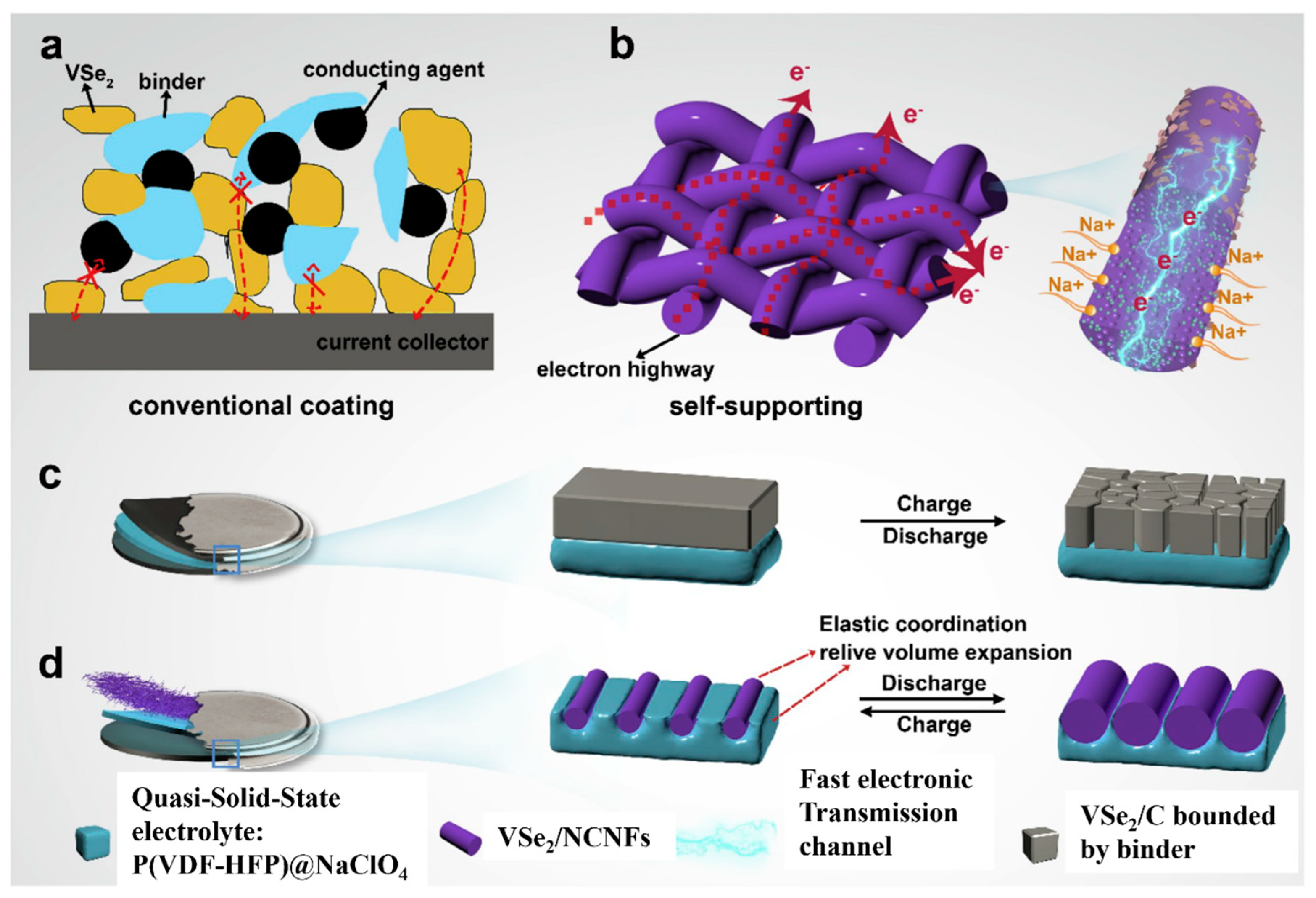
- Wu, Y.; Zhong, W.; Tang, W.; Zhang, L.; Chen, H.; Li, Q.; Xu, M.; Bao, S.-j. Flexible electrode constructed by encapsulating ultrafine VSe2 in carbon fiber for quasi-solid-state sodium ion batteries. J. Power Sources 2020, 470, 228438. [Google Scholar] [CrossRef]
- Li, Z.; Zhao, H.; Wang, J.; Lv, P.; Zhang, Z.; Zeng, Z.; Xia, Q. 3D heterostructure Fe3O4/Ni/C nanoplate arrays on Ni foam as binder-free anode for high performance lithium-ion battery. Electrochim. Acta 2015, 182, 398–405. [Google Scholar] [CrossRef]
- Shen, Z.; Hu, Y.; Chen, Y.; Chen, R.; He, X.; Zhang, X.; Shao, H.; Zhang, Y. Controllable synthesis of carbon-coated Sn–SnO2–carbon-nanofiber membrane as advanced binder-free anode for lithium-ion batteries. Electrochim. Acta 2016, 188, 661–670. [Google Scholar] [CrossRef]
- Wang, X.; Zhang, M.; Liu, E.; He, F.; Shi, C.; He, C.; Li, J.; Zhao, N. Three-dimensional core-shell Fe2O3@carbon/carbon cloth as binder-free anode for the high-performance lithium-ion batteries. Appl. Surf. Sci. 2016, 390, 350–356. [Google Scholar] [CrossRef]
- Shin, N.; Kim, M.; Ha, J.; Kim, Y.-T.; Choi, J. Flexible anodic SnO2 nanoporous structures uniformly coated with polyaniline as a binder-free anode for lithium ion batteries. J. Electroanal. Chem. 2022, 914, 116296. [Google Scholar] [CrossRef]
- Liu, H.; Liu, R.; Ma, Y.; Wang, L.; Sun, C.; Xu, T.; Liu, H.; Wang, J. Cobalt oxide arrays anchored to copper foam as efficient binder-free anode for lithium ion batteries. ChemPhysChem 2023, 24, e202300290. [Google Scholar] [CrossRef] [PubMed]
- Lou, F.; Zhou, H.; Tran, T.D.; Buan, M.E.M.; Vullum-Bruer, F.; Rønning, M.; Walmsley, J.C.; Chen, D. Coaxial carbon/metal oxide/aligned carbon nanotube arrays as high-performance anodes for lithium ion batteries. ChemSusChem 2014, 7, 1335–1346. [Google Scholar] [CrossRef] [PubMed]
- Kakarla, A.K.; Narsimulu, D.; Yu, J.S. High capacity performance of NiCo2O4 nanostructures as a binder-free anode material for lithium-ion batteries. Int. J. Energy Res. 2021, 45, 13355–13364. [Google Scholar] [CrossRef]
- Yang, Y.; Xia, J.; Guan, X.; Wei, Z.; Yu, J.; Zhang, S.; Xing, Y.; Yang, P. In situ growth of CoP nanosheet arrays on carbon cloth as binder-free electrode for high-performance flexible lithium-ion batteries. Small 2022, 18, 2204970. [Google Scholar] [CrossRef]
- Zhang, Z.; Wang, Z.L.; Lu, X. Multishelled Si@Cu microparticles supported on 3D Cu current collectors for stable and binder-free anodes of lithium-ion batteries. ACS Nano 2018, 12, 3587–3599. [Google Scholar] [CrossRef]
- Yuan, W.; Luo, J.; Pan, B.; Qiu, Z.; Huang, S.; Tang, Y. Hierarchical shell/core CuO nanowire/carbon fiber composites as binder-free anodes for lithium-ion batteries. Electrochim. Acta 2017, 241, 261–271. [Google Scholar] [CrossRef]
- Ding, Y.; Li, P.; Wang, J.; Li, X.; Liu, Y.; Bai, H.; Zhang, H. Rationally designed rGO@CNTs@CNFs film as self-supporting binder-free Si electrodes for high-performance lithium-ion batteries. J. Colloid Interface Sci. 2023, 631, 249–257. [Google Scholar] [CrossRef]
- Yang, Y.; Li, J.; Chen, D.; Fu, T.; Sun, D.; Zhao, J. Binder-free carbon-coated silicon–reduced graphene oxide nanocomposite electrode prepared by electrophoretic deposition as a high-performance anode for lithium-ion batteries. ChemElectroChem 2016, 3, 757–763. [Google Scholar] [CrossRef]
- Zhai, J.; Lei, Z.; Sun, K.; Zhu, S. MXene enabled binder-free FeOF cathode with high volumetric and gravimetric capacities for flexible lithium ion batteries. Electrochim. Acta 2022, 423, 140595. [Google Scholar] [CrossRef]
- Tong, X.; Yang, B.; Li, F.; Gu, M.; Zhan, X.; Tian, J.; Huang, S.; Wang, G. Binder-free CoMn2O4 nanoflower particles/graphene/carbon nanotube composite film for a high-performance lithium-ion battery. Inorganics 2023, 11, 314. [Google Scholar] [CrossRef]
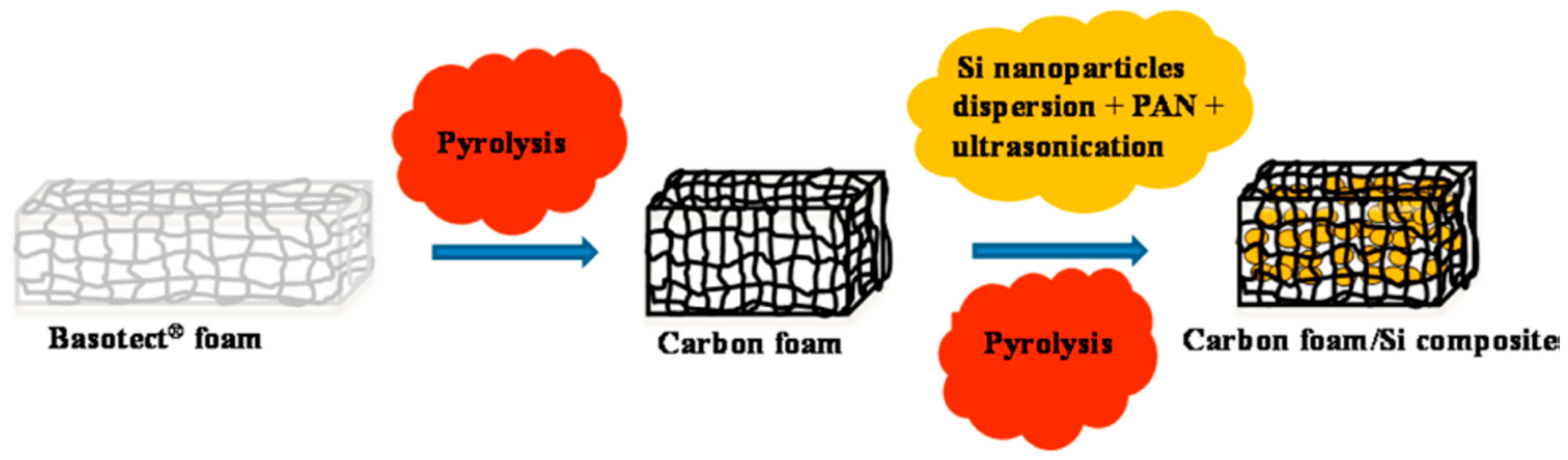
- Roy, A.K.; Zhong, M.; Schwab, M.G.; Binder, A.; Venkataraman, S.S.; Tomovicć, Z. Preparation of a binder-free three-dimensional carbon foam/silicon composite as potential material for lithium ion battery anodes. ACS Appl. Mater. Interfaces 2016, 8, 7343–7348. [Google Scholar] [CrossRef] [PubMed]
- Li, D.; Xia, J. Electrospinning of nanofibers: Reinventing the wheel? Adv. Mater. 2004, 16, 1151–1170. [Google Scholar] [CrossRef]
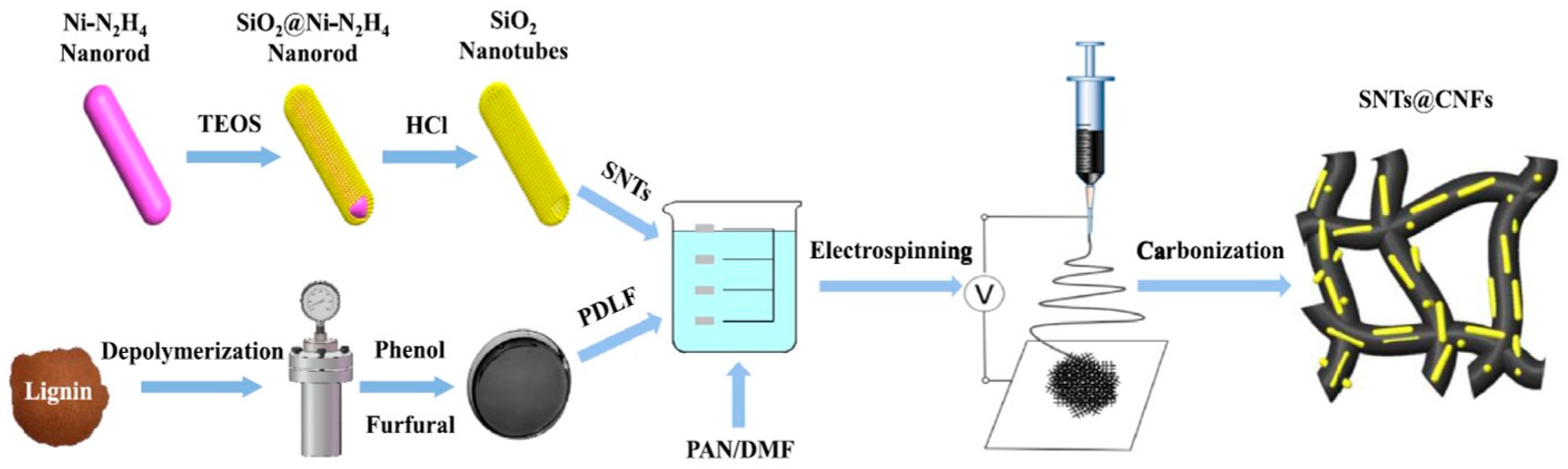
- Si, L.; Yan, K.; Li, C.; Huang, Y.; Pang, X.; Yang, X.; Sui, D.; Zhang, Y.; Wang, J.; Xu, C.C. Binder-free SiO2 nanotubes/carbon nanofibers mat as superior anode for lithium-ion batteries. Electrochim. Acta 2022, 404, 139747. [Google Scholar] [CrossRef]
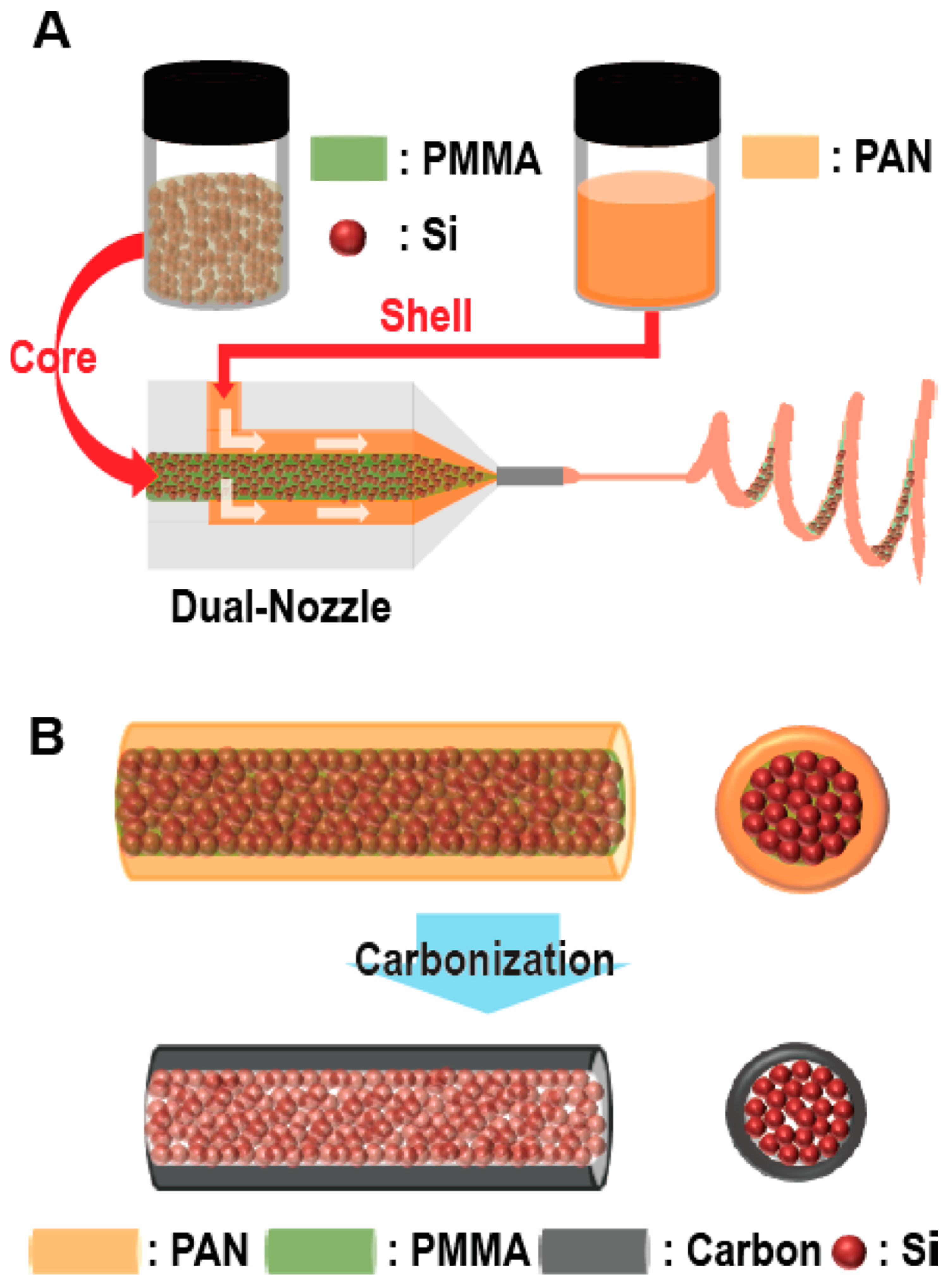
- Hwang, T.H.; Lee, Y.M.; Kong, B.-S.; Seo, J.-S.; Choi, J.W. Electrospun core−shell fibers for robust silicon nanoparticle-based lithium ion battery anodes. Nano Lett. 2012, 12, 802–807. [Google Scholar] [CrossRef]
- Liu, Y.; Wang, W.; Gu, L.; Wang, Y.; Ying, Y.; Mao, Y.; Sun, L.; Peng, X. Flexible CuO nanosheets/reduced-graphene oxide composite paper: Binder-free anode for high-performance lithium-ion batteries. ACS Appl. Mater. Interfaces 2013, 5, 9850–9855. [Google Scholar] [CrossRef]
- Hu, B.; Zhou, X.; Xu, J.; Wang, X.; Yuan, N.; Ge, S.; Ding, J. Excellent rate and low temperature performance of lithium-ion batteries based on binder-free Li4Ti5O12 electrode. ChemElectroChem 2020, 7, 716–722. [Google Scholar] [CrossRef]
- Zhu, Y.; Han, X.; Xu, Y.; Liu, Y.; Zheng, S.; Xu, K.; Hu, L.; Wang, C. Electrospun Sb/C fibers for a stable and fast sodium-ion battery anode. ACS Nano 2013, 7, 6378–6386. [Google Scholar] [CrossRef]
- Fu, L.; Wang, X.; Ma, J.; Zhang, C.; He, J.; Xu, H.; Chai, J.; Li, S.; Chai, F.; Cui, G. Graphene-encapsulated copper tin sulfide submicron spheres as high-capacity binder-free anode for lithium-ion batteries. ChemElectroChem 2017, 4, 1124–1129. [Google Scholar] [CrossRef]
- Wang, Y.; Zhou, H.; Xiao, J.; Yuan, A. Graphene aerogel supported Fe-Co selenide nanocubes as binder-free anodes for lithium-ion batteries. Z. Anorg. Allg. Chem. 2021, 647, 1025–1030. [Google Scholar] [CrossRef]
- Luo, S.; Wang, K.; Wang, J.; Jiang, K.; Li, Q.; Fan, S. Binder-free LiCoO2 /carbon nanotube cathodes for high-performance lithium ion batteries. Adv. Mater. 2012, 24, 2294–2298. [Google Scholar] [CrossRef] [PubMed]
- Wang, T.; Shi, S.; Li, Y.; Zhao, M.; Chang, X.; Wu, D.; Wang, H.; Peng, L.; Wang, P.; Yang, G. Study of microstructure change of carbon nanofibers as binder-free anode for high-performance lithium-ion batteries. ACS Appl. Mater. Interfaces 2016, 8, 33091–33101. [Google Scholar] [CrossRef] [PubMed]
- Lee, D.; Lee, H.; Kim, Y.-T.; Lee, K.; Choi, J. Phase-tuned nanoporous vanadium pentoxide as binder-free cathode for lithium ion battery. Electrochim. Acta 2020, 330, 135192. [Google Scholar] [CrossRef]
- Jin, J.; Shi, Z.-q.; Wanga, C.-y. Electrochemical performance of electrospun carbon nanofibers as free-standing and binder-free anodes for sodium-ion and lithium-ion batteries. Electrochim. Acta 2014, 141, 302–310. [Google Scholar] [CrossRef]
- Xia, J.; Yuan, Y.; Yan, H.; Liu, J.; Zhang, Y.; Liu, L.; Zhang, S.; Li, W.; Yang, X.; Shu, H.; et al. Electrospun SnSe/C nanofibers as binder-free anode for lithium–ion and sodium-ion batteries. J. Power Sources 2020, 449, 227559. [Google Scholar] [CrossRef]
- Luo, W.; Calas, A.; Tang, C.; Li, F.; Zhou, L.; Mai, L. Ultralong Sb2Se3 nanowire-based free-standing membrane anode for lithium/sodium ion batteries. ACS Appl. Mater. Interfaces 2016, 8, 35219–35226. [Google Scholar] [CrossRef]
- Gao, Y.; Wang, B. Binder- and conductive additive-free Ga2O3 nanowires as a self-healing anode for lithium storage. Prog. Nat. Sci. Mater. Int. 2023, 33, 203–210. [Google Scholar] [CrossRef]
- Diem, A.M.; Fenk, B.; Bill, J.; Burghard, Z. Binder-free V2O5 cathode for high energy density rechargeable aluminum-ion batteries. Nanomaterials 2020, 10, 247. [Google Scholar] [CrossRef]
- Lee, S.H.; Grant, P.S. Spray fabrication of additive-free electrodes for advanced Lithium-ion storage technologies. J. Colloid Interface Sci. 2023, 651, 742–749. [Google Scholar] [CrossRef] [PubMed]
- Shi, C.; Takeuchi, S.; Alexander, G.V.; Hamann, T.; O’Neill, J.; Dura, J.A.; Wachsman, E.D. High sulfur loading and capacity retention in bilayer garnet sulfurized-polyacrylonitrile/lithium-metal batteries with gel polymer electrolytes. Adv. Energy Mater. 2023, 13, 2301656. [Google Scholar] [CrossRef]
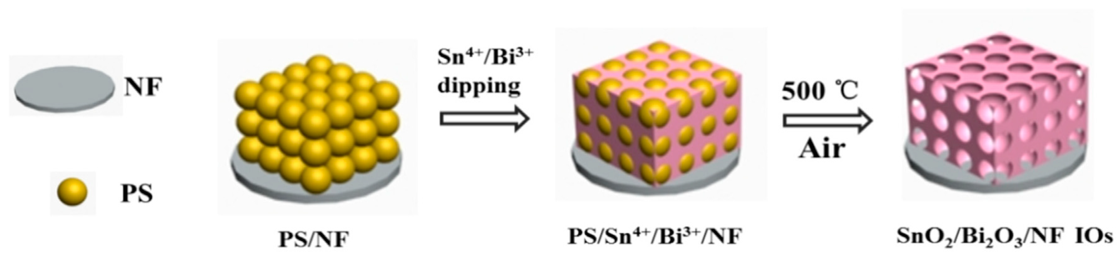
- Zhang, R.; Fang, T.; Ni, L.; Zhu, Y.; Shen, Y.; Xie, A.; Lao, L. SnO2/Bi2O3/NF heterojunction with ordered macro/meso-pore structure as an advanced binder-free anode for lithium ion batteries. J. Electroanal. Chem. 2022, 907, 115894. [Google Scholar] [CrossRef]
- Huo, J.; Xue, Y.; Liu, Y.; Guo, S. Low-temperature preparation of mesoporous TiO2 honeycomb-like structure on TiO2 nanotube arrays as binder-free anodes for lithium-ion batteries. J. Electroanal. Chem. 2020, 863, 114088. [Google Scholar] [CrossRef]
- Huo, K.; Li, X.; Gao, B.; Wang, L.; Li, Q.; Peng, X.; Zhang, X.; Fu, J.; Chu, P.K. Self-supporting and binder-free anode film composed of beaded stream-like Li4Ti5O12 nanoparticles for high-performance lithium-ion batteries. ChemElectroChem 2016, 3, 1301–1305. [Google Scholar] [CrossRef]
- Cao, Y.; Zhang, A.-Q.; Luo, H.-W.; Gao, H.-L.; Yan, J.; Yan, Q.-Q.; Liu, Y.-M.; Zhang, Y. Hierarchical urchin-like Fe2O3 structures grown directly on Ti foils for binder-free lithium-ion batteries with fast charging/discharging properties. Inorg. Chem. Commun. 2020, 113, 107769. [Google Scholar] [CrossRef]
- Koura, N.; Etoh, K.; Idemoto, Y.; Matsumoto, F. Electrochemical behavior of graphite–lithium intercalation electrode in AlCl3–EMIC–LiCl–SOCl2 room-temperature molten salt. Chem. Lett. 2001, 30, 1320–1321. [Google Scholar] [CrossRef]
- Wang, Z.; Zeng, F.; Zhao, S.; Li, C.; Yang, W.; Leng, Z.; Wang, L.; Cheng, Y. In-situ fabricate highly ordered 3D Cervantite@TiO2 nanoarrays integrated electrode as additive-free anode for lithium/sodium-ion batteries. J. Power Sources 2022, 548, 232054. [Google Scholar] [CrossRef]
- Ha, D.-H.; Islam, M.A.; Robinson, R.D. Binder-free and carbon-free nanoparticle batteries: A method for nanoparticle electrodes without polymeric binders or carbon black. Nano Lett. 2012, 12, 5122–5130. [Google Scholar] [CrossRef]
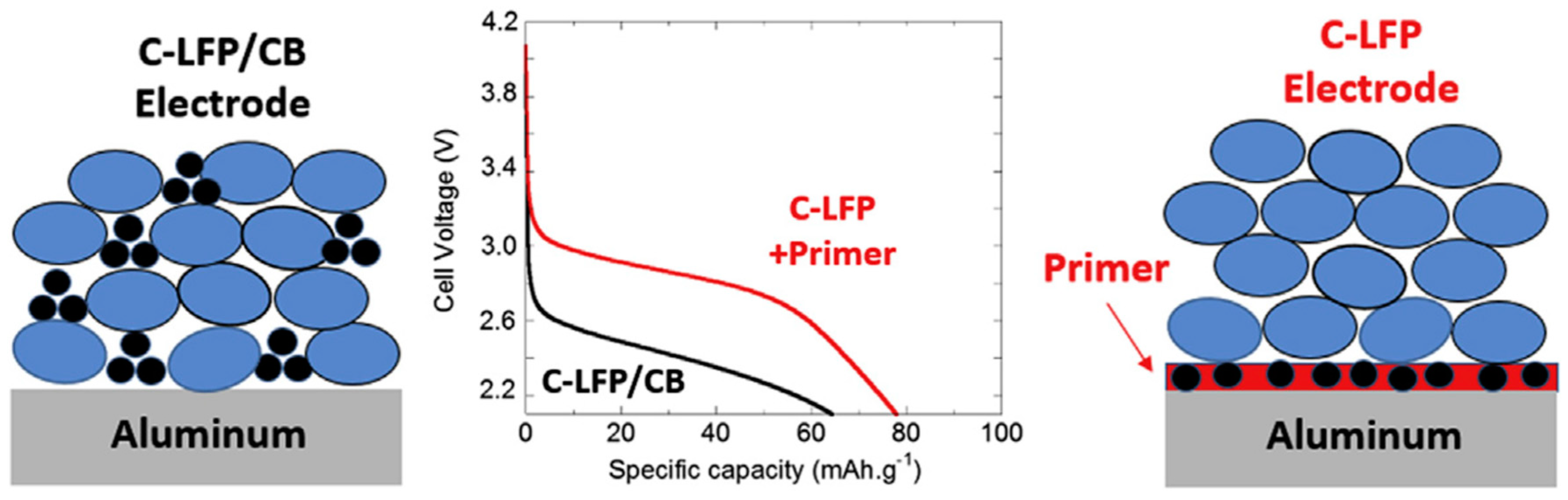
- Busson, C.; Blin, M.-A.; Guichard, P.; Soudan, P.; Crosnier, O.; Guyomard, D.; Lestriez, B. A primed current collector for high performance carbon-coated LiFePO4 electrodes with no carbon additive. J. Power Sources 2018, 406, 7–17. [Google Scholar] [CrossRef]
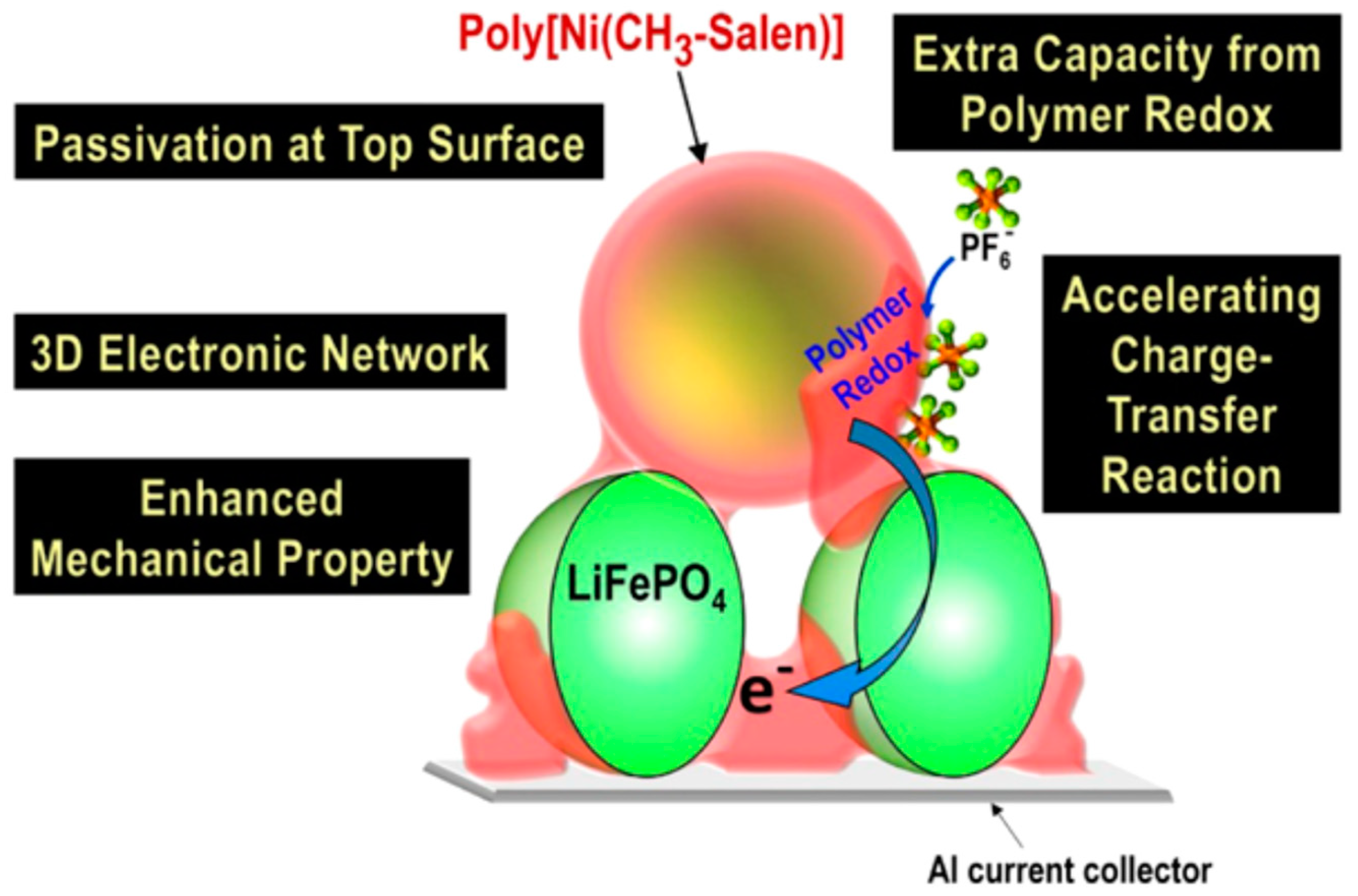
- O’Meara, C.; Karushev, M.P.; Polozhentceva, I.A.; Dharmasena, S.; Cho, H.; Yurkovich, B.J.; Kogan, S.; Kim, J.-H. Nickel−salen-type polymer as conducting agent and binder for carbon-free cathodes in lithium-ion batteries, ACS Appl. Mater. Interfaces 2019, 11, 525–533. [Google Scholar] [CrossRef] [PubMed]
- Wang, H.; Emanuelsson, R.; Liu, H.; Mamedov, F.; Strømme, M.; Sjödin, M. A conducting additive-free high potential quinone-based conducting redox polymer as lithium ion battery cathode. Electrochim. Acta 2021, 391, 138901. [Google Scholar] [CrossRef]
- Friebe, C.; Zens, C.; Kupfer, S.; Schubert, U.S. Additive-free organic radical batteries prepared through electrochemical polymerization of TEMPO-decorated terthiophene. J. Phys. Chem. C 2023, 127, 1333–1344. [Google Scholar] [CrossRef]
- Chen, Z.; Yong, F.; Wang, Y.; Zhao, M.; Yu, F. Developing a p-toluenesulfonic acid monohydrate-assisted electrodeposition method to synthesize an additive-free polypyrrole cathode for high-rate stability and high gravimetric/volumetric capacity Li-ion batteries. ACS Sustain. Chem. Eng. 2023, 11, 144–154. [Google Scholar] [CrossRef]
- Lee, S.; Hong, J.; Jung, S.-K.; Ku, K.; Kwon, G.; Seong, W.M.; Kim, H.; Yoon, G.; Kang, I.; Hong, K.; et al. Charge-transfer complexes for high-power organic rechargeable batteries. Energy Storage Mater. 2019, 20, 462–469. [Google Scholar] [CrossRef]
- Fujihara, Y.; Kobayashi, H.; Takaishi, S.; Tomai, T.; Yamashita, M.; Honma, I. Electrical conductivity-relay between organic charge-transfer and radical salts toward conductive additive-free rechargeable battery. ACS Appl. Mater. Interfaces 2020, 12, 25748–25755. [Google Scholar] [CrossRef]
- Yang, L.; Wang, P.; Zhang, S.; Wang, Y.; Zang, L.; Zhu, H.; Yin, J.; Yang, H.Y. Flexible and additive-free organic electrodes for aqueous sodium ion batteries. J. Mater. Chem. A 2020, 8, 22791–22801. [Google Scholar] [CrossRef]
- Pignier, V.; Toumieux, S.; Davoisne, C.; Caroff, M.; Jamali, A.; Pilard, S.; Mathiron, D.; Cailleu, D.; Delattre, F.; Singh, D.P.; et al. Toward conductive additive free organic electrode for lithium-ion battery using supramolecular columnar organization. Small 2024, 20, 2305701. [Google Scholar] [CrossRef]
- Mishra, S.; Singh, M.K.; Pandey, D.; Rai, D.K.; Raghuvanshi, A. A two-dimensional semiconducting Cu(I)-MOF for binder and conductive additive-free supercapattery. J. Mater. Chem. A 2024, 12, 4534–4543. [Google Scholar] [CrossRef]
- Wei, C.; Fei, H.; Tian, Y.; An, Y.; Zeng, G.; Feng, J.; Qian, Y. Room-temperature liquid metal confined in MXene paper as a flexible, freestanding, and binder-free anode for next-generation lithium-ion batteries. Small 2019, 15, 1903214. [Google Scholar] [CrossRef]
- Deshpande, R.D.; Li, J.; Cheng, Y.-T.; Verbrugge, M.W. Liquid metal alloys as self-healing negative electrodes for lithium ion batteries. J. Electrochem. Soc. 2011, 158, A845–A849. [Google Scholar] [CrossRef]
- Ponnuru, H.; Marriam, I.; Rambukwella, I.; Zheng, J.-C.; Yan, C. Recent advances in liquid metals for rechargeable batteries. Adv. Funct. Mater. 2023, 2309706. [Google Scholar] [CrossRef]
- Han, B.; Yang, Y.; Shi, X.; Zhang, G.; Gong, L.; Xu, D.; Zeng, H.; Wang, C.; Gu, M.; Deng, Y. Spontaneous repairing liquid metal/Si nanocomposite as a smart conductive-additive-free anode for lithium-ion battery. Nano Energy 2018, 50, 359–366. [Google Scholar] [CrossRef]
- Zuo, X.; Zhu, J.; Müller-Buschbaum, P.; Cheng, Y.-J. Silicon based lithium-ion battery anodes: A chronicle perspective review. Nano Energy 2017, 31, 113–143. [Google Scholar] [CrossRef]
- Kwon, T.W.; Choi, J.W.; Coskun, A. The emerging era of supramolecular polymeric binders in silicon anodes. Chem. Soc. Rev. 2018, 47, 2145. [Google Scholar] [CrossRef] [PubMed]
- Zhao, Y.-M.; Yue, F.-S.; Li, S.-C.; Zhang, Y.; Tian, Z.-R.; Xu, Q.; Xin, S.; Guo, Y.-G. Advances of polymer binders for silicon-based anodes in high energy density lithium-ion batteries. InfoMat 2021, 3, 460–501. [Google Scholar] [CrossRef]
- Unno, H.; Nagata, T.; Fujimoto, N.; Fukuda, M. Fe-based metal foils for current collectors in Li-secondary batteries. Nippon Steel Gihou 2019, 412, 173–183. Available online: https://www.nipponsteel.com/tech/report/pdf/412-26.pdf (accessed on 9 September 2024).
- Yue, H.; Wang, S.; Yang, Z.; Li, Q.; Lin, S.; He, D. Ultra-thick porous films of graphene-encapsulated silicon nanoparticles as flexible anodes for lithium ion batteries. Electrochim. Acta 2015, 174, 688–695. [Google Scholar] [CrossRef]
- Salvatierra, R.V.; Raji, A.-R.O.; Lee, S.-K.; Ji, Y.; Li, L.; Tour, J.M. Silicon nanowires and lithium cobalt oxide nanowires in graphene nanoribbon papers for full lithium ion battery. Adv. Energy Mater. 2016, 6, 1600918. [Google Scholar] [CrossRef]
- Shao, J.; Yang, Y.; Zhang, X.; Shen, L.; Bao, N. 3D yolk–shell structured Si/void/rGO free-standing electrode for lithium-ion battery. Materials 2021, 14, 2836. [Google Scholar] [CrossRef]
- Shao, F.; Li, H.; Yao, L.; Xu, S.; Li, G.; Li, B.; Zou, C.; Yang, Z.; Su, Y.; Hu, N.; et al. Binder-free, flexible, and self-standing non-woven fabric anodes based on graphene/Si hybrid fibers for high-performance Li-ion batteries. ACS Appl. Mater. Interfaces 2021, 13, 27270–27277. [Google Scholar] [CrossRef] [PubMed]
- Kim, S.Y.; Kim, C.H.; Yang, C.-M. Binder-free silicon anodes wrapped in multiple graphene shells for high-performance lithium-ion batteries. J. Power Sources 2021, 486, 229350. [Google Scholar] [CrossRef]
- Zhao, Y.; Pan, X.; Liu, M.; Chen, X.; Zhang, R.; Zhiyong, X. The fabrication of silicon/dual-network carbon nanofibers/carbon nanotubes as free-standing anodes for lithium-ion batteries. RSC Adv. 2023, 13, 35026. [Google Scholar] [CrossRef] [PubMed]
- Eldona, C.; Hawari, N.H.; Hamid, F.H.; Dempwolf, W.; Iskandar, F.; Peiner, E.; Wasisto, H.S.; Sumboja, A. A free-standing polyaniline/silicon nanowire forest as the anode for lithium-ion batteries. Chem Asian J. 2022, 17, e202200946. [Google Scholar] [CrossRef] [PubMed]
- Xia, F.; Kim, S.B.; Cheng, H.; Lee, J.M.; Song, T.; Huang, Y.; Rogers, J.A.; Paik, U.; Park, W.I. Facile synthesis of free-standing silicon membranes with three-dimensional nanoarchitecture for anodes of lithium ion batteries. Nano Lett. 2013, 13, 3340–3346. [Google Scholar] [CrossRef]
- Zhao, Y.; Peng, L.; Ding, Y.; Yu, G. Amorphous silicon honeycombs as a binder/ carbon-free, thin-film Li-ion battery anode. Chem. Commun. 2014, 50, 12959. [Google Scholar] [CrossRef]
- Liu, B.; Wang, X.; Chen, H.; Wang, Z.; Chen, D.; Cheng, Y.-B.; Zhou, C.; Shen, G. Hierarchical silicon nanowires-carbon textiles matrix as a binder-free anode for high-performance advanced lithium-ion batteries. Sci. Rep. 2013, 3, 1622. [Google Scholar] [CrossRef]
- Sun, L.; Wang, X.; Susantyoko, R.A.; Zhang, Q. Copper–silicon core–shell nanotube arrays for free-standing lithium ion battery anodes. J. Mater. Chem. A 2014, 2, 15294. [Google Scholar] [CrossRef]
- Kim, H.-J.; Lee, J.; Lee, S.E.; Kim, W.; Kim, H.J.; Choi, D.-G.; Park, J.-H. Polymer-free vertical transfer of silicon nanowires and their application to energy storage. ChemSusChem 2013, 6, 2144–2148. [Google Scholar] [CrossRef]
- Farid, G.; Amade-Rovira, R.; Ospina, R.; Bertran-Serra, E. Surface modification of silicon nanowires via drop-casting for high-performance Li-ion battery electrodes: SiNWs decorated with molybdenum oxide nanoparticles. J. Energy Storage 2024, 78, 110104. [Google Scholar] [CrossRef]
- Kumar, S.K.; Choudhury, R.; Martha, S.K. Binder and conductive additive free silicon electrode architecturesfor advanced lithium-ion batteries. J. Energy Storage 2018, 17, 417–422. [Google Scholar] [CrossRef]
- Zeng, Z.; Wang, C.; Zeng, M.; Fu, L. Gallium-based liquid metals in rechargeable batteries: From properties to applications. Small 2024, 2311099. [Google Scholar] [CrossRef] [PubMed]
- Sun, Y.; Lopez, J.; Lee, H.-W.; Liu, N.; Zheng, G.; Wu, C.-L.; Sun, J.; Liu, W.; Chung, J.W.; Bao, Z.; et al. A Stretchable graphitic carbon/Si anode enabled by conformal coating of a self-healing elastic polymer. Adv. Mater. 2016, 28, 2455–2461. [Google Scholar] [CrossRef] [PubMed]
- Cao, L.; Huang, T.; Zhang, Q.; Cui, M.; Xu, J.; Xiao, R. Porous Si/Cu Anode with high initial coulombic efficiency and volumetric capacity by comprehensive utilization of laser additive manufacturing-chemical dealloying. ACS Appl. Mater. Interfaces 2020, 12, 57071–57078. [Google Scholar] [CrossRef] [PubMed]
- Zhuo, Y.; Sun, H.; Uddin, M.H.; Barr, M.K.S.; Wisser, D.; Roßmann, P.; Esper, J.D.; Tymek, S.; Döhler, D.; Peukert, W.; et al. An additive-free silicon anode in nanotube morphology as a model lithium ion battery material. Electrochim. Acta 2021, 388, 138522. [Google Scholar] [CrossRef]
- Koo, B.; Kim, H.; Cho, Y.; Lee, K.T.; Choi, N.-S.; Cho, J.A. Highly cross-linked polymeric binder for high-performance silicon negative electrodes in lithium ion batteries. Angew. Chem. Int. Ed. 2012, 51, 8762–8767. [Google Scholar] [CrossRef]
- Liu, W.-R.; Guo, Z.-Z.; Young, W.-S.; Shieh, D.-T.; Wu, H.-C.; Yang, M.-H.; Wu, N.-L. Effect of electrode structure on performance of Si anode in Li-ion batteries: Si particle size and conductive additive. J. Power Sources 2005, 140, 139–144. [Google Scholar] [CrossRef]
- Gowda, S.R.; Pushparaj, V.; Herle, S.; Girishkumar, G.; Gordon, J.G.; Gullapalli, H.; Zhan, X.; Ajayan, P.M.; Reddy, A.L.M. Three-dimensionally engineered porous silicon electrodes for Li ion batteries. Nano Lett. 2012, 12, 6060–6065. [Google Scholar] [CrossRef]
- Liu, N.; Wu, H.; McDowell, M.T.; Yao, Y.; Wang, C.; Cui, Y. A yolk-shell design for stabilized and scalable Li-ion battery alloy anodes. Nano Lett. 2012, 12, 3315–3321. [Google Scholar] [CrossRef]
- Park, Y.-K.; Park, G.-G.; Park, J.-G.; Lee, J.-W. Robust free-standing electrodes for flexible lithium-ion batteries prepared by a conventional electrode fabrication process. Electrochim. Acta 2017, 247, 371–380. [Google Scholar] [CrossRef]
- Boaretto, N.; Almenara, J.; Mikhalchan, A.; Marcilla, R.; Vilatela, J.J. A route to high-toughness battery electrodes. ACS Appl. Energy Mater. 2019, 2, 5889–5899. [Google Scholar] [CrossRef]
- Johannisson, W.; Ihrner, N.; Zenkert, D.; Johansson, M.; Carlstedt, D.; Asp, L.E.; Sieland, F. Multifunctional performance of a carbon fiber UD lamina electrode for structural batteries. Compos. Sci. Technol. 2018, 168, 81–87. [Google Scholar] [CrossRef]
- Hwang, C.; Song, W.-J.; Han, J.-G.; Bae, S.; Song, G.; Choi, N.-S.; Park, S.; Song, H.-K. Foldable electrode architectures based on silver-nanowire-wound or carbon-nanotube-webbed micrometer-scale fibers of polyethylene terephthalate mats for flexible lithium-ion batteries. Adv. Mater. 2018, 30, 1705445. [Google Scholar] [CrossRef] [PubMed]
- Evanoff, K.; Benson, J.; Schauer, M.; Kovalenko, I.; Lashmore, D.; Ready, W.J.; Yushin, G. Ultra strong silicon-coated carbon nanotube nonwoven fabric as a multifunctional lithium-ion battery anode. ACS Nano 2012, 6, 9837–9845. [Google Scholar] [CrossRef] [PubMed]
- Wu, Y.; Wu, H.; Luo, S.; Wang, K.; Zhao, F.; Wei, Y.; Liu, P.; Jiang, K.; Wang, J.; Fan, S. Entrapping electrode materials within ultrathin carbon nanotube network for flexible thin film lithium ion batteries. RSC Adv. 2014, 4, 20010–20016. [Google Scholar] [CrossRef]
- Ha, S.H.; Shin, K.H.; Park, H.W.; Lee, Y.J. Flexible lithium ion batteries with high areal capacity enabled by smart conductive textiles. Small 2018, 14, 1703418. [Google Scholar] [CrossRef]
- Zhang, C.; Park, S.-H.; Seral-Ascaso, A.; Barwich, S.; McEvoy, N.; Boland, C.S.; Coleman, J.N.; Gogotsi, Y.; Nicolosi, V. High capacity silicon anodes enabled by MXene viscous aqueous ink. Nat. Commun. 2019, 10, 849. [Google Scholar] [CrossRef]
- Gaikwad, A.M.; Khau, B.V.; Davies, G.; Hertzberg, B.; Steingart, D.A.; Arias, A.C. A high areal capacity flexible lithium-ion battery with a strain-compliant design. Adv. Energy Mater. 2015, 5, 1401389. [Google Scholar] [CrossRef]
- Wang, K.; Luo, S.; Wu, Y.; He, X.; Zhao, F.; Wang, J.; Jiang, K.; Fan, S. Super-aligned carbon nanotube films as current collectors for lightweight and flexible lithium ion batteries. Adv. Funct. Mater. 2013, 23, 846–853. [Google Scholar] [CrossRef]
- Liu, X.; Qi, W.; Zou, T.; Fan, D.; Guo, S.; Zhao, Y.; Wang, L. Flexible current collector–free LiFePO4/carboncomposite film for high-performance lithium-ion batteries. Ionics 2019, 25, 939–947. [Google Scholar] [CrossRef]
- Boaretto, N.; Dávila, B.; Sevilla, S.; García, G.; Mikhalchan, A.; Rana, M.; Yusuf, A.; Martinez, L.U.; García, M.C.; Palma, J.; et al. Thermoconformable, flexible lithium-ion batteries. Adv. Mater. Technol. 2022, 7, 2101635. [Google Scholar] [CrossRef]
- Kang, S.; Hong, S.Y.; Kim, N.; Oh, J.; Park, M.; Chung, K.Y.; Lee, S.-S.; Lee, J.; Son, J.G. Stretchable lithium-ion battery based on reentrant micro-honeycomb electrodes and cross-linked gel electrolyte. ACS Nano 2020, 14, 3660–3668. [Google Scholar] [CrossRef] [PubMed]
- Rana, M.; Boaretto, N.; Mikhalchan, A.; Santos, M.V.; Marcilla, R.; Vilatela, J.J. Composite fabrics of conformal MoS2 grown on CNT fibers: Tough battery anodes without metals or binders. ACS Appl. Energy Mater. 2021, 4, 5668–5676. [Google Scholar] [CrossRef]
- Wu, X.; Wang, Z.; Qin, C.; Wang, X.; Xie, H.; Kang, Z.; Su, Z. Hierarchical and highly stable conductive network cathode for ultraflexible Li−S batteries. ACS Appl. Energy Mater. 2018, 1, 2689–2697. [Google Scholar] [CrossRef]


| Active Materials | Current Collector | Preparation Method | Observed Capacity (mAhg−1) | Schematics of Active Materials on a CC | References |
|---|---|---|---|---|---|
| Fe3O4/Ni/Carbon nanoplate arrays | Ni foam | Hydrothermal method combined with a subsequent CVD heat treatment | 832.5 |  | [70] |
| Composite comprising Sn, SnO2, and a porous carbon-nanofiber membrane | none | Electrospinning followed by carbonization | 712 | 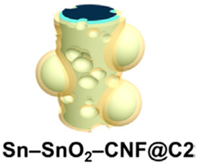 | [71] |
| Core–shell Fe2O3@ carbon | Carbon cloth | Hydrothermal method | 1635.8 | 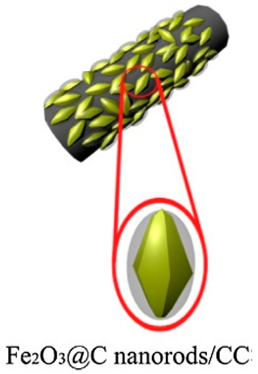 | [72] |
| Nanoporous SnO2@polyaniline | Cu foil | Deposition of Sn, anodization of Sn to nanoporous SnO2, and electropolymerization of polyaniline | 440 | 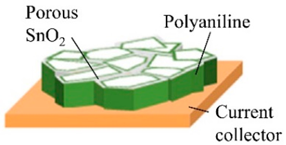 | [73] |
| Cobalt oxide arrays | Cu foam | Hydrothermal method followed by post-annealing process | 1287 |  | [74] |
| Coaxial carbon/metal oxide/aligned carbon nanotube (ACNT) | Stainless-steel foil | On an ACNT surface on stainless-steel foil, metal oxide coating through spontaneous deposition, followed by carbon coating through CVD | 374 | 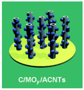 | [75] |
| NiCo2O4 (NCO) nanowire | Cu foam | Solvothermal method | 2637 | 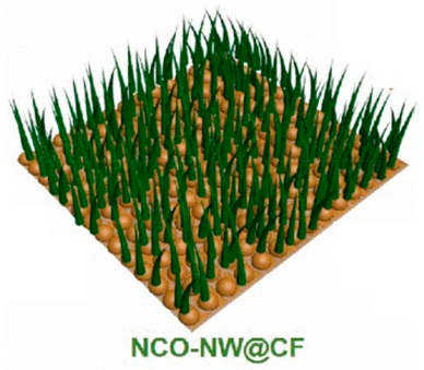 | [76] |
| CoP nanosheet arrays | Carbon cloth (CC) | Electrodeposition of a Co precursor on CC, followed by in situ phosphorization routes | 919 | 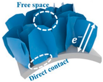 | [77] |
| 3D Cu@Si@Cu microparticles | 3D Cu foil | Magnetron sputtering of Si on the surface of 3D Cu foil | 766 | 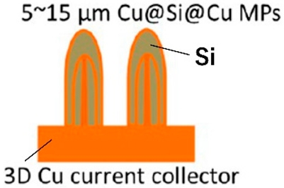 | [78] |
| Hierarchical shell/core CuO nanowire/carbon fiber composites | Carbon fiber | Coating of the carbon fiber surface with Cu, solid-phase sintering of the fiber, and heat-treatment of the coated Cu to CuO | 598 |  | [79] |
| Active Materials | Preparation Method | Observed Capacity (mAhg−1) | Schematic of Active Materials on the 3D Matrix | Scanning Electron Microscopy Image of Active Materials in the Three-Dimensional Conductive Structure | References |
|---|---|---|---|---|---|
| CuO nanosheet/reduced graphene oxide composite | Vacuum filtration and hydrothermal reduction processes | 736.8 |  |  | [88] |
| Li4Ti5O12/carbon nanotube nanosheet | Hydrothermal method and a final calcination procedure | 140 |  |  | [89] |
| Sb/C fibers | Electrospinning method | 422 | 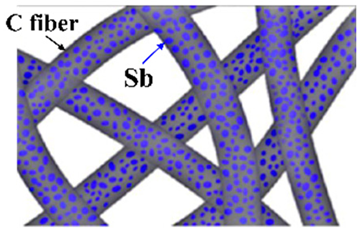 | 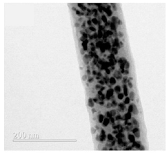 | [90] |
| Cu2Sn3S7/Cu2SnS3/SnS2 (CTS) reduced graphene oxide (RGO) | Ultrasonication/filtration/calcination | 965 | 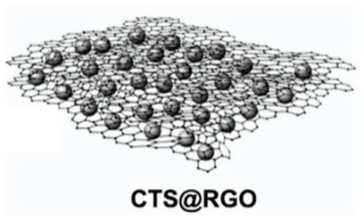 | 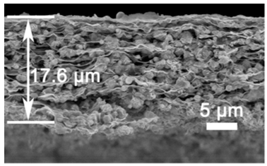 | [91] |
| FeCoSe2@ graphene aerogel (GA) | Hydrothermal precursor of Fe-Co and graphene oxide/freeze-drying/selenization | 500 | 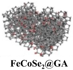 |  | [92] |
| Fe3O4/superaligned carbon nanotube (SACNT) | Ultrasonication and co-deposition procedure with LiCoO2-SACNT. | 151.4 mA hg−1 at 0.1 C with retention of 98.4% after 50 cycles |  | 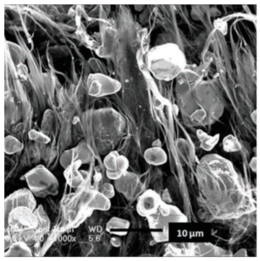 | [93] |
| Schematic of Active Materials on the 3D Matrix | Preparation Method | Cycle Ability (mAhg−1) | Rate Capability | References |
|---|---|---|---|---|
 | Synergistic effects of in situ self-assembly of GO sheets and simultaneous deposition of Si nanoparticles on the GO sheets; finally, the mixture was vacuum-filtered to form anode layers. | 2370 mAhg−1 over 50 cycles at a current of 210 mAg−1 | 1000 mAhg−1 at a current density of 4200 mAg−1 after 500 cycles. | [128] |
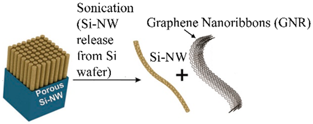 | Porous Si nanowires and graphene nanoribbons can be entangled into a mat, therefore forming Si-NW GNR papers using simple filtration methods. | 2500 mAhg−1 at the first cycle and 1500 mAhg−1 at 300 cycles at a current of 1 Ag−1 | 1800 and 400 mAhg−1 at 1 and 10 Ag−1, respectively. | [129] |
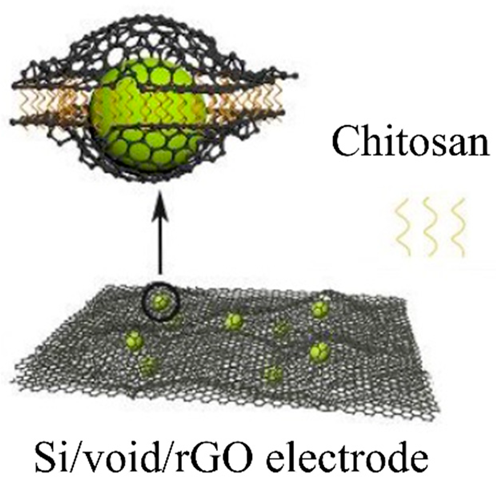 | During the electrostatic interaction between GO and chitosan, which results in a rapid coagulation phenomenon, Si/SiO2 nanoparticles dispersed in GO can be uniformly encapsulated between GO sheets. | 1129.2 mAhg−1 after 200 charge/discharge cycles at 200 mAg−1 | 469.2 mAhg−1 at 4000 mAg−1 | [130] |
 | Short GO fibers wrapping Si nanoparticles (GOFs/Si) were fabricated by the wet-spinning method. | 920 mAhg−1 after 100 charge/discharge cycles. Furthermore, 580 mAhg−1 after 400 charge/discharge cycles | - | [131] |
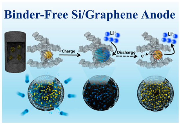 | Reduced graphene oxide (RGO) and Si nanoparticles were prepared as spherical composite structures using an easy spray-drying process. The microspheres were homogeneously incorporated into a 3D porous graphene aerogel (GA) structure using an aerogel synthesis process. | High initial discharge capacity (1217 mAh g−1) and excellent cyclic stability (462 mAh g−1 at 1.0 C after 200 cycles) | 819 mAh g−1 at 10 C | [132] |
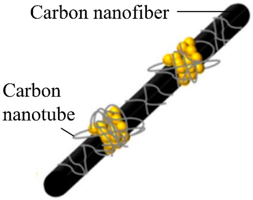 | A novel freestanding Si/C anode is synthesized by combining electrospinning and in situ CVD, in which Si nanoparticles are composited with a conducting dual network composed of carbon nanofibers and in situ deposited carbon nanotubes. | 639.9 mAhg−1 and a capacity retention rate of 69.9% after 100 cycles at a current density of 0.1 A g−1. | 880, 775 and 660 mAhg−1 at 0.1, 0.2 and 0.5 C, respectively. | [133] |
 | Facile metal-assisted chemical etching and in situ polymerization of aniline are employed to produce a dense 1D polyaniline/Si nanowire forest without noticeable agglomeration. | A stable capacity capped at 2 mAhcm−2 for 346 cycles of charge–discharge | - | [134] |
 | Hydrothermal growth of a hexagonal array of ZnO nanopillar templates through nanosphere lithography and then a thin Si layer coating on the ZnO template by CVD. Finally, Si membranes are transferred. | 2414 mAh g−1 after 100 cycles at a current density of 0.1 C, maintaining 82.3% of the initial charge capacity. | Charge capacity >1220 mAh g−1 at 8 C. | [135] |
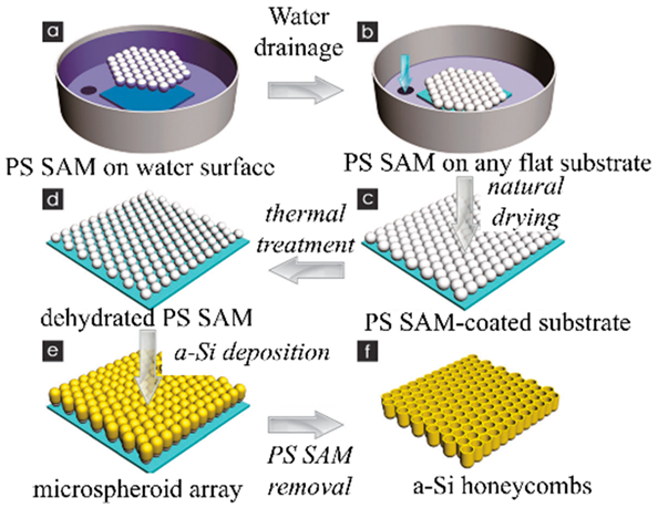 | Self-assembled monolayers of polystyrene spheres (PSS) were used as the template. Amorphous Si was deposited on the surface of ordered PSS with magnetron sputtering. Amorphous Si thin films with honeycombed structures were prepared. | 1730 mA h g−1 after 200 cycles | Discharge capacity retention was ~60% from 0.42 Ag−1 to 8.4 Ag−1. | [136] |
| Schematic of Active Material Layers | Preparation Method | Cycle Ability (mAhg−1) | Rate Capability | References |
|---|---|---|---|---|
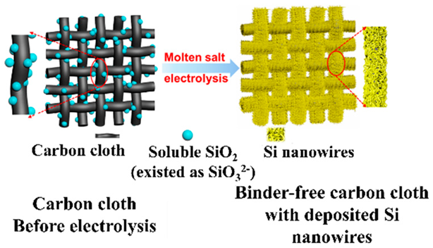 | Ultrathin surface oxide layer (∼1 nm in thickness) is directly electrodeposited on carbon cloth from soluble SiO2 in molten chloride salts | 711 mAh g−1 after 200 charge/ discharge cycles at 1000 mA g−1. | - | [68] |
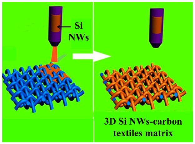 | Carbon textiles were gradually coated with as-synthesized Si nanowires (NWs) by a homogeneous suspension of Si NWs. Hierarchical Si-NW–carbon textile anodes were achieved after thermal treatment | 2950 mAh g−1 at 0.2 C | 950 mAh g−1 at a high rate of 5 C | [137] |
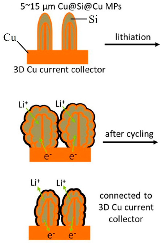 | Cu(OH)2 nanowire arrays were synthesized by the reaction of NaOH and (NH4)2S2O8 with Cu foils. Subsequently, Cu(OH)2@Si core−shell structures were obtained by magnetron sputtering. Repeated deposition of Si or Cu via magnetron sputtering, thermal evaporation, or atomic layer deposition led to the formation of multishelled wires | 1000 mAhg−1 at 1 C. After 200 cycles, the capacity retention was 81%. | 1300 and 990 mAhg−1 at 1 and 10 C. | [78] |
 | The core Cu nanotube array (CNA) was produced on a Si nanopillar structure through RF magnetron sputtering. The CNA spontaneously delaminated from the wafer. The amorphous Si shell was prepared with plasma-enhanced CVD on the CNA | Initial specific capacity of 2473 mAh g−1. After 400 charge and discharge cycles, the average coulombic efficiency was 98.44%. | 2079, 1846, 1625, 1316, 1013, 633 and 411 mAhg−1 at 0.3, 0.5, 1, 2, 4, 8 and 12 C, respectively | [138] |
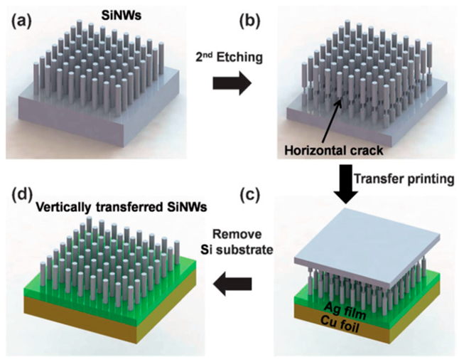 | Vertically aligned Si nanowire (Si-NW) anodes by applying the transfer printing method through a metal adhesion layer. Si-NW array after the first metal-assisted chemical etching process | 2150 mAhg−1 during 60 cycles | 2141, 2106, 2017, 1937, 1860, and 1760 mAh g−1, at 0.2 C, 0.5 C, 1 C, 2 C, 3 C, and 5 C. | [139] |
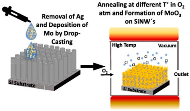 | Deposition of MoO3 nanoparticles via a unique drop-casting technique onto prefabricated Si-NW arrays, fabricated using a straightforward one-step metal-assisted chemical etching process | 1.34 mAh cm−2 at 100 μAcm−2 for 10 cycles. After 200 cycles, 1.23 mAh cm−2 | 1.25, 1.03, 0.78, 0.60 and 0.44 mAh cm−2 at 1 (100), 2 (200), 4 (400), 8 (800) and 10 C (1000 μA cm−2). | [140] |
| Schematics of active Material Layers | Preparation Method | Cycle Ability (mAhg−1) | Rate Capability | References |
|---|---|---|---|---|
 | The Si nanoparticles are pressure-embedded onto Cu foil CC without using any organic BD or conductive carbon additive | An initial reversible capacity of 950 mAhg−1 at 0.1 C. More than 650 mAhg−1 during 500 cycles at 0.5 C. | 800 mAh g−1 at 5 C. | [141] |
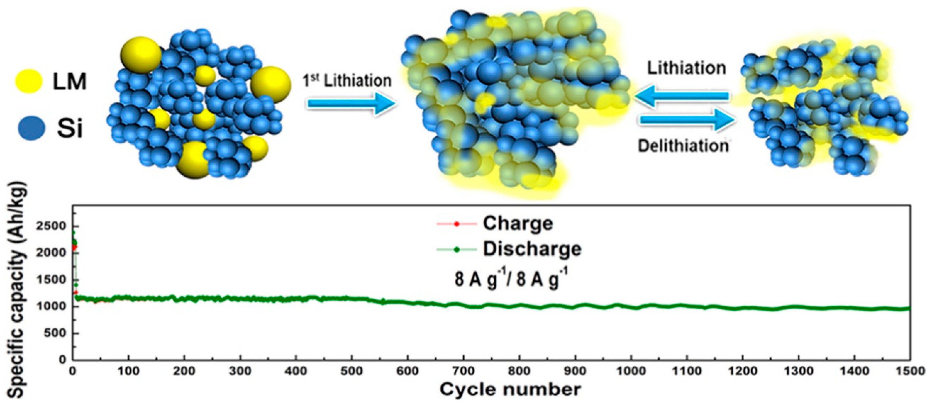
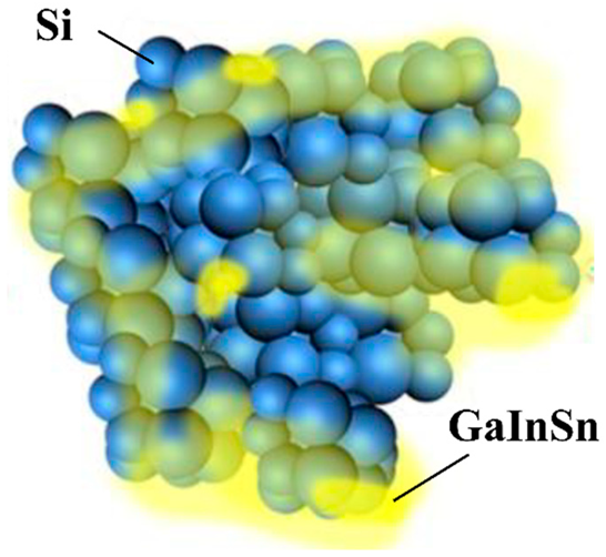 | GaInSn samples were prepared with an atomic ratio of 7:2:1. GaInSn was added as a spontaneous repairing LM to the EAM layer of Si | 2300 mAh g−1 at 500 mA g−1 at first cycle. 968 mAh g−1 after 1500 charge–discharge cycles at 8 A g−1 with 81.3% retention. | 360 mAh g−1 at 20 A g−1, equivalence of 55 C. | [123] |
 | Ni foams were coated with carbon materials to form stretchable CCs. Si was deposited on the stretchable CCs. Finally, the Si was coated with a self-healing elastic polymer | 722 mAh g−1 after 100 charge/discharge cycles. The corresponding capacity retention is as high as 83% with 0.17% decay per cycle. | - | [143] |
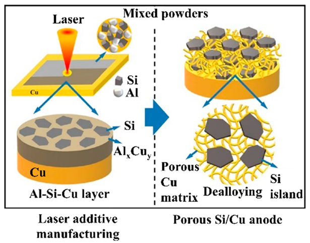 | Planar Si islands were embedded in the porous Cu matrix through combined laser additive manufacturing and chemical dealloying | Initial volumetric capacity of 2131 mAh cm−3. 1697 mAh cm−3 after 100 cycles at 0.20 mA cm−2. | Capacity retention of 92% and 88% at 1.20 and 1.72 mAh cm−2 compared with the capacity at 0.20 mA cm−2. | [144] |
 | ALD of SiO2 on well-ordered Al2O3 nanopores. Reduction of SiO2 to Si. Sputter-coating of Au on one side of the sample and gluing with conductive Cu adhesive tape onto Cu foil as a CC | 120 mAhcm−2 at the first cycle and a retention of 51% after 100 cycles. | - | [145] |
| Toughness | Sp Capacity | |||||
|---|---|---|---|---|---|---|
| Electrode Type | J cm−3 | J g−1 | Active Mass Fraction | mAh g−1 | mAh cm−2 | Ref. |
| CF/SBE/Cu | 5 | 4.3 | 0.07 | 16 | 0.33 | [152] |
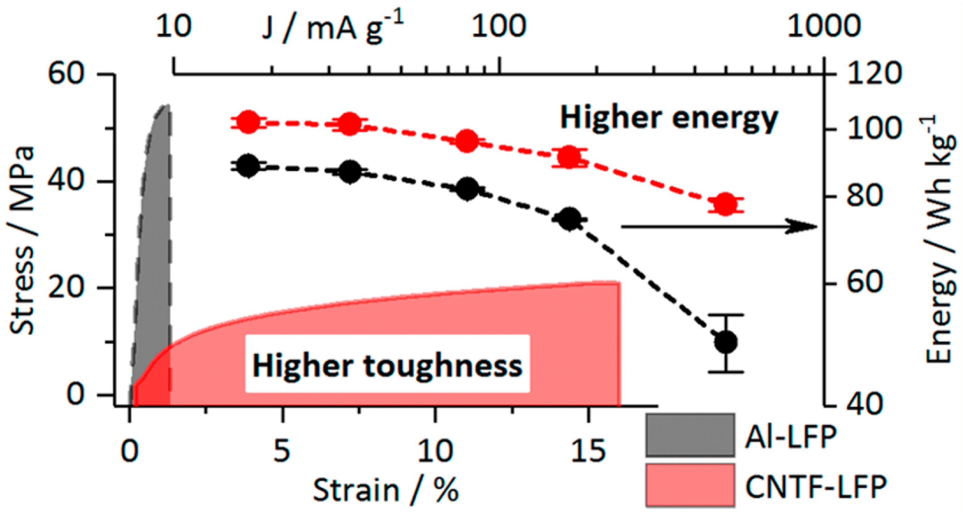
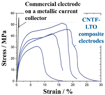
| CNTF-LFP | 1.7 | 1.6 | 0.81 | 132 | 0.5 | [151] |
| LTO-AgNW$MF | ~0.5 | ~0.2 | 0.7 | 110 | 0.8–3 | [153] |
| Si/CNT | 0.25 | 0.19 | 0.47 | 494 | 1.16 | [154] |
| LFP/CNT | 0.022 | 0.04 | 0.95 | 150 | 0.073 | [155] |
| LTO/CNT | 0.021 | 0.04 | 0.95 | 151 | 0.075 | [155] |
| LTO/rGO | 0.09 | 0.045 | <0.16 | 26 | 1.3 | [156] |
| LCO/rGO | 0.09 | 0.045 | <0.16 | 26 | 1.3 | [156] |
| Si/MX | 0.007 | 0.014 | 0.09 | 288 | 2.9 | [157] |
| LCO/PA/CNT | 0.01 | 0.01 | 0.57 | 76 | 1.2 | [158] |
| LTO/PA/CNT | 0.01 | 0.01 | 0.59 | 78 | 1.34 | [158] |
| graphite/SACNT | 0.006 | 0.007 | 0.8 | 268 | 1.92 | [159] |
| LCO/SACNT | 0.004 | 0.002 | 0.97 | 146 | 0.6 | [93] |
| LFP/C | 0.003 | (~0.003) | 0.8 | 125 | 0.3 | [160] |
| Schematics of Active Material Layers | Tensile Stress–Strain Curve | Preparation Method | References |
|---|---|---|---|
 |  | A mixture of EAM, BD, and CAs was homogenized with a disperser coated by a doctor blade over the CNTF | [161] |
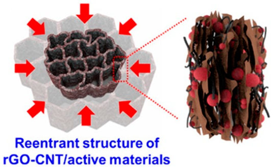 |  | Re-entrant microhoneycomb graphene−carbon nanotube (CNT)/EAM composite electrodes were prepared with directional crystallization, freeze-drying, and thermal reduction | [162] |
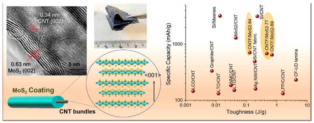 |  | The EAM and CC are formed as a single nanostructured composite network comprising macroscopic fabrics of CNTFs covered with conformal MoS2 grown preferentially aligned over the graphitic layers | [163] |
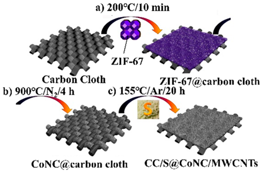 |  | Preparation of S@CoNC on carbon cloth by direct thermolysis of zeolitic imidazolate frameworks (ZIF)-67 and sulfur encapsulation by a melt-diffusion method | [164] |
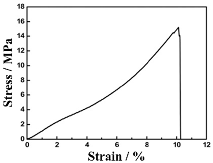
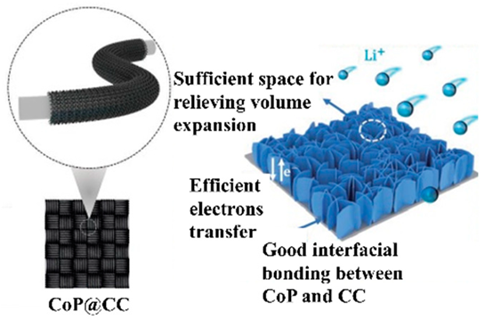 |  | CoP nanosheet arrays were grown directly on carbon cloth (CC) via easy one-step electrodeposition followed by an in situ phosphorization strategy | [77] |
Disclaimer/Publisher’s Note: The statements, opinions and data contained in all publications are solely those of the individual author(s) and contributor(s) and not of MDPI and/or the editor(s). MDPI and/or the editor(s) disclaim responsibility for any injury to people or property resulting from any ideas, methods, instructions or products referred to in the content. |
© 2024 by the authors. Licensee MDPI, Basel, Switzerland. This article is an open access article distributed under the terms and conditions of the Creative Commons Attribution (CC BY) license (https://creativecommons.org/licenses/by/4.0/).
Share and Cite
Matsumoto, F.; Fukunishi, M. Review of Current Collector-, Binder-, Conductive Additive-Free, and Freestanding Electrodes in Lithium and Related Batteries. Batteries 2024, 10, 330. https://doi.org/10.3390/batteries10090330
Matsumoto F, Fukunishi M. Review of Current Collector-, Binder-, Conductive Additive-Free, and Freestanding Electrodes in Lithium and Related Batteries. Batteries. 2024; 10(9):330. https://doi.org/10.3390/batteries10090330
Chicago/Turabian StyleMatsumoto, Futoshi, and Mika Fukunishi. 2024. "Review of Current Collector-, Binder-, Conductive Additive-Free, and Freestanding Electrodes in Lithium and Related Batteries" Batteries 10, no. 9: 330. https://doi.org/10.3390/batteries10090330