Abstract

Development of an Intelligent Cooling Stave as Part of the Cooling System of a Blast Furnace †

ArcelorMittal Poland S.A., Al. Jozefa Pilsudskiego 92, 41-308 Dabrowa Gornicza, Poland
*
Author to whom correspondence should be addressed.
Presented at the 31st International Conference on Modern Metallurgy Iron and Steelmaking 2024, Chorzów, Poland, 25–27 September 2024.
Proceedings 2024, 108(1), 13; https://doi.org/10.3390/proceedings2024108013
Published: 2 September 2024

1. Introduction

In the realm of engineering, the evolution of cooling systems for blast furnaces stands as a testament to innovation’s crucial role in enhancing industrial processes. Among these advancements, the development of intelligent cooling staves has emerged as a pivotal stride towards optimizing the efficiency, safety, and sustainability of blast furnace operations. This article delves into the intricacies of integrating intelligent cooling staves within the cooling framework of a blast furnace, highlighting the profound impact of intelligent technologies on traditional industrial practices.

2. Process Description

The primary purpose of a blast furnace is to chemically reduce and physically transform iron oxides into liquid iron, known as hot metal. This hot metal serves as the input for the Basic Oxygen Furnace (BOF). Hot metal is an alloy of iron, carbon, and other elements, with the carbon content being around 4%. Due to its brittleness and lack of plasticity, hot metal cannot undergo mechanical processing. In the blast furnace charging process, batches of charge material are typically loaded in a cyclical sequence from the top hoppers into the furnace using a top charging system. Modern blast furnaces utilize a top charging system with two hoppers, into which coke and sinter are loaded. The blast furnace, a type of shaft furnace, features distinct geometries at each segment from top to bottom, corresponding to the processes occurring within the furnace (Figure 1) [1].
Today’s blast furnaces are advanced versions of traditional furnaces, equipped with sophisticated instruments and control systems. Key aspects of the production process involve operating and controlling the blast furnace to manage internal temperatures at various segments and to monitor impurity levels online [2].
The charge materials for the blast furnace, a mixture of sinter, iron ore, coke, and fluxes, are introduced at the top of the shaft. Improper distribution of these materials can disrupt furnace operations and reduce hot metal output. Heated air, along with gaseous, liquid, or powdered fuel, is introduced through openings near the bottom of the shaft, just above the hearth crucible. This hot air ignites the injected fuel and much of the coke charged from the top, generating the necessary heat and producing reducing gas to remove oxygen from the ore. The reduced iron melts and descends to the bottom of the hearth. The fluxes combine with impurities in the ore to form slag, which also melts and accumulates on top of the liquid iron in the hearth [1,2].
The blast furnace process begins when a hot blast is blown into the furnace via tuyeres at temperatures of up to 1200 °C. This hot blast ignites the fuel accumulated in front of the tuyeres, producing an intense flame visible through the peepholes of the raceway [3,4].

3. Methodology

The project was divided into several phases as follows:
  • Identification of the existing state of affairs and development of conceptual assumptions for a new cooling technology for the metallurgical unit: An inventory of the blast furnace cooling system was carried out and historical data on furnace operation were collected. The interconnection topology of the cooling staves was prepared for further computer simulations. Additional sensors were placed on one of the staves to provide verifiable measurement data. A thermal-fluid and strength model of the metallurgical unit cooling stave was also developed.
  • Development of new technology for the metallurgical unit cooling system: The effect of changing the diameter of the channels in the cooling staves and the cooling water flow rate was investigated. The effect of stopping the flow of cooling water in selected channels on the temperature distribution in the stave and the change in heat flux density was also investigated. In addition, a ‘virtual second layer’ was modelled in the case of a copper stave to check the effect of adding an additional layer behind the main cooling channels on the temperature distribution in the stave. A numerical coupled thermal-strength model was developed for a copper cooling stave to estimate the stress levels resulting from the resulting temperature distributions.
  • Preparation of the technological design, verification, construction, and commissioning of the demonstration plant: As part of this phase, recommendations and design guidelines were developed for the design of the cooling staves. The design of the individual cooling staves was verified in terms of the achieved quality parameters of the cooling system. Various solutions for connecting the cooling system using individual cooling staves were analyzed.
  • Demonstration plant testing and optimization: Phase 4 analyzed data from the operation of the blast furnace cooling system. The data analyzed were the temperatures and flow rates of the cooling water and the temperatures of the staves. The averaged values of the measured data were compared with the simulation results for the new cooling system. Analyses were also carried out to establish correlations between the technical parameters. Current and proposed furnace operating points were analyzed. As a result of the analyses, new process guidelines were prepared.

4. Results and Discussion

The study aimed to evaluate the cooling efficiency, durability, and overall performance of the cooling staves under various operational conditions. We conducted a comprehensive analysis, utilizing both theoretical models and empirical data collected from operational blast furnaces. This approach allowed us to identify key factors that influence the cooling performance and to recommend improvements that can enhance the efficiency and lifespan of the cooling staves. Table 1 shows the effect of the second cooling layer on the temperature of the stave. It can be seen that the stave temperature is much lower when the second layer is working. After the first cooling layer has worn off, the stave continues to work. This results in an extended BF campaign.
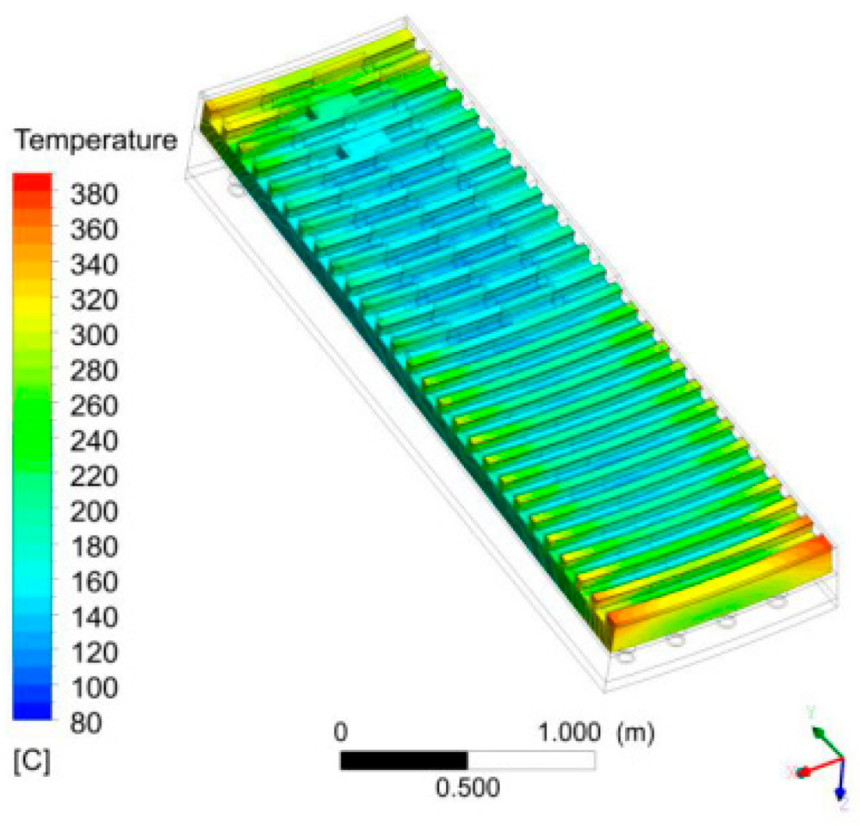
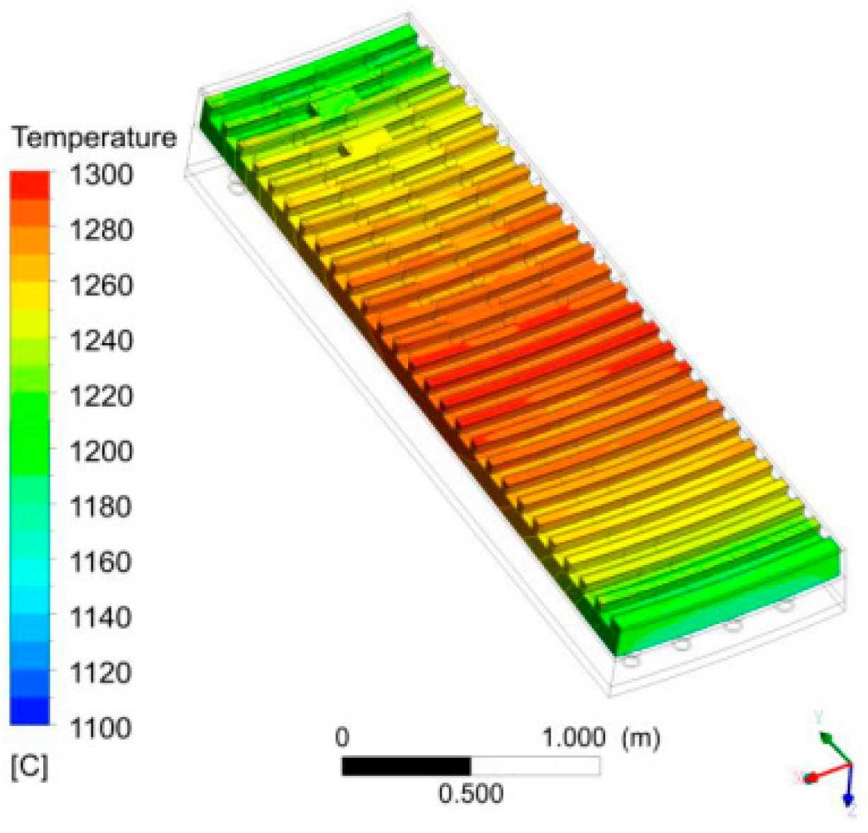
Figure 2 and Figure 3 show a comparison of the surface temperatures of the cooling stave with four inoperative cooling channels and with the second cooling layer either functioning or not. For the variant with the second cooling layer functioning, the stave temperatures are low, at around 200 °C. For the non-cooled variant, the stave temperature is around 1200 °C, which is extremely high. The stave will deteriorate rapidly in this condition.

5. Conclusions

This work describes the design of a cooling stave with a second cooling layer. The results of the work show that the operation of the second cooling layer affects the operation of the cooling stave and the heat extraction from the blast furnace. The ability to regulate the heat uptake of the cooling staves results in better utilization of the technological fuel.

Author Contributions

Conceptualization, M.B. and A.G.; methodology, M.B. and A.G.; software, M.B.; validation, M.B. and A.G.; formal analysis, A.G.; investigation, M.B. and A.G.; resources, A.G.; data curation, M.B.; writing—original draft preparation, M.B.; writing—review and editing, M.B.; visualization, M.B.; supervision, A.G.; project administration, A.G.; funding acquisition, A.G. All authors have read and agreed to the published version of the manuscript.

Funding

The project entitled “Development and demonstration of an intelligent cooling system for a metallurgical unit by closing and integrating water circuits while increasing the operational reliability of the metallurgical process and improving the efficiency of the use of industrial cooling water.” co-financed under the grant agreement number: POIR.01.01.01-00-0034/18 signed with the National Centre for Research and Development under the Smart Growth Operational Program 2014–2020.

Institutional Review Board Statement

Not applicable.

Informed Consent Statement

Not applicable.

Data Availability Statement

Dataset is available on request from the authors.

Conflicts of Interest

Author Marek Berlinski and Agata Grzybowska were employed by the company ArcelorMittal Poland S.A. The funding sponsors had no role in the design of the study; in the collection, analyses, or interpretation of data; in the writing of the manuscript, and in the decision to publish the results.

References

  1. Dobrzański, L.A.; Gawron, M.; Berliński, M. The use of artificial neural networks for the prediction of a chemical composition of hot metal produced in blast furnace. J. Achiev. Mater. Manuf. Eng. 2014, 67, 32–38. [Google Scholar]
  2. Burgo, J.A. The Manufacture of Pig Iron in the Blast Furnace. In The Making, Shaping and Treating of Steel, 11th ed.; Wakelin, D.H., Ed.; AIST: Warrendale, PA, USA, 1999; pp. 699–740. [Google Scholar]
  3. Geerdes, M.; Toxopeus, H.; van der Vliet, C. Modern Blast Furnace Ironmaking; IOS Press: Amsterdam, The Netherlands, 2009. [Google Scholar]
  4. Król, L. Blast Furnace, Onstruction and Equipment; Silesian University of Technology Press: Gliwice, Poland, 1989. [Google Scholar]
Figure 1. Blast furnace.
Proceedings 108 00013 g001
Figure 2. Temperature distribution for a stave with 0/4 working channel + second cooling layer.
Proceedings 108 00013 g002
Figure 3. Temperature distribution for a stave with 0/4 working channel + without second cooling layer.
Proceedings 108 00013 g003
Table 1. Performance of the stave in different states.
NoStave Operating ConditionsHeat Flux DensityThermocouple Temperature∆T Water Temperature in Channel
12/4 working cooling channel62 kW/m2167.6 °C9.98 °C
22/4 working cooling channel
+ second cooling layer
65 kW/m2120.8 °C5.76 °C
30/4 working channel7 kW/m21277.3 °C-
40/4 working channel
+ second cooling layer
61 kW/m2164.3 °C-
Disclaimer/Publisher’s Note: The statements, opinions and data contained in all publications are solely those of the individual author(s) and contributor(s) and not of MDPI and/or the editor(s). MDPI and/or the editor(s) disclaim responsibility for any injury to people or property resulting from any ideas, methods, instructions or products referred to in the content.