Article

Nanostructured C@CuS Core–Shell Framework with High Lithium-Ion Storage Performance

1
Shaanxi Key Laboratory of Optoelectronic Functional Materials and Devices, School of Materials and Chemical Engineering, Xi’an Technological University, Xi’an 710021, China
2
Ames National Laboratory, U.S. Department of Energy and Department of Physics and Astronomy, Iowa State University, Ames, IA 50011, USA
*
Authors to whom correspondence should be addressed.
J. Compos. Sci. 2024, 8(9), 375; https://doi.org/10.3390/jcs8090375
Submission received: 19 July 2024 / Revised: 10 September 2024 / Accepted: 18 September 2024 / Published: 21 September 2024
(This article belongs to the Special Issue Advancements in Composite Materials for Energy Storage Applications)

Abstract

:
In this study, we have synthesized a nanostructured core–shell framework of carbon-coated copper sulfide (C@CuS) through a one-step precipitation technique. The carbon sphere template facilitated the nucleation of CuS nanostructures. The synthesized nanocomposites have demonstrated remarkable lithium-ion storage capabilities when utilized as an anode in lithium-ion batteries. Notably, they exhibit an impressive rate capability of 314 mAh g−1 at a high current density of 5000 mA g−1, along with excellent long-term cycle stability, maintaining 463 mAh g−1 at 1000 mA g−1 after 800 cycles. This superior performance is due to the core–shell architecture of the composite, where the carbon core enhances the conductivity of CuS nanoparticles and mitigates volume expansion, thus preventing capacity loss. Our study not only elucidates the significance of carbon in the construction of nano-heterojunctions or composite electrodes but also presents a practical approach to significantly boost the electrochemical performance of CuS and other metal sulfides.

Graphical Abstract

1. Introduction

The increasing demands for fast charging and discharging performance, high energy density, and power density in lithium-ion batteries (LIBs) have surpassed the capabilities of commercial batteries [1,2,3]. Therefore, there is an urgent need to develop new materials with improved electrochemical performance for the next generation of LIBs. The anode materials play a crucial role in determining the electrochemical performance of batteries. In recent years, various materials such as silicon, lithium metal, metal oxides, and metal sulfides have been proposed as potential replacements for graphite anodes in LIBs [4,5,6,7,8].
Transition metal sulfides, specifically MxSy (M = Mn, Fe, Ni, Co, Cu), exhibit a theoretical specific capacity that is twice as high as that of commercial graphite electrodes. Moreover, most metal sulfides have a voltage plateau above 1.0 V, which prevents the formation of lithium dendrites and ensures safety [9]. These characteristics make transition metal sulfides promising candidates for the anode materials in next-generation LIBs [10,11,12]. However, their poor cycle performance and rate performance limit their applications, which are due to volume expansion during charging and discharging and low conductivity [13,14,15]. To overcome these challenges, several effective strategies have been proposed, including nano crystallization [16], hollow nanostructure design [17], composite materials [18], and the fabrication of heterojunctions [19].
The combination of transition metal sulfides with carbon as hybrid materials has shown potential in improving cycle life and rate performance. By incorporating carbon, the volume expansion caused by lithium intercalation can be alleviated, thus the integrity of the structure is maintained [20,21,22]. For instance, Wang et al. synthesized a carbon nanotubes/CuS (CNTs/CuS) composite material with excellent cycle performance using a microwave-assisted hydrothermal method [23]. This composite exhibited a reversible capacity of 569 mA h g−1 after 450 cycles at a current density of 400 mA g−1. Li et al. prepared a CuS/graphene composite via a one-pot microwave-assisted method, demonstrating enhanced cycle stability and rate performance with a capacity of 348 mAh g−1 at a current density of 2000 mA g−1 after 1000 cycles [19]. Zhang et al. synthesized a CuS/reduced graphene oxide (rGO) composite through a stepwise method which exhibited a high initial discharge specific capacity of 882 mAh g−1 along with a stable cycle performance and high coulombic efficiency [24]. The improved electrochemical performance of these composites is primarily attributed to the introduction of carbon materials, which not only alleviate volume expansion but also enhance conductivity.
However, using high-cost materials like graphene or carbon nanotubes to prepare CuS-based composites is not very economical. Additionally, the complex and costly preparation processes, involving multiple steps, hinder the industrialization and widespread application of these composites. Therefore, there is a need to develop a simple, inexpensive, and scalable synthesis method for CuS-based composites. In this study, we present a one-step precipitation method to fabricate C@CuS composites, incorporating a carbon sphere template for nanostructured CuS heterogeneous nucleation. Acetylene black (C45), a cheaper alternative to graphene or carbon nanotubes, was used as a carbon source in the experiment. Moreover, the prepared composites exhibit good electrochemical properties. During the synthesis process, CuS nanoparticles quickly nucleate and grow on the carbon skeleton assembled with carbon nanoparticles, ensuring the formation of C@CuS core–shell frameworks. This structure improves the overall conductivity of the composite and mitigates volume expansion during lithiation. The core–shell structure dramatically enhances the reaction kinetics, cyclic stability, and rate performance of the material.

2. Materials and Methods

2.1. Materials

The reagents utilized included acetylene black (C45, Sinopharm Chemical Reagent Co., Ltd., Shanghai, China, analytical reagent grade, AR, ≥99.5%), thioacetamide (TAA, Sinopharm Chemical Reagent Co., Ltd., Shanghai, China, analytical reagent grade, AR, ≥99.0%), copper(II) nitrate trihydrate (Cu(NO3)2·3H2O, Sinopharm Chemical Reagent Co., Ltd., Shanghai, China, analytical reagent grade, AR, ≥99.5%), and ethanol (Sinopharm Chemical Reagent Co., Ltd., Shanghai, China, analytical reagent grade, AR, ≥99.7%).

2.2. Preparation of CuS Nanoparticles and Nanostructured C@CuS Core–Shell Framework

The composite material was prepared using a liquid-phase precipitation method. First, 0.282 g of C45, along with 0.75 g of TAA and 1.205 g of Cu(NO3)2·3H2O, were added to a mixed solution of water and ethanol (V1:V2 = 3:7), totaling 100 mL. Next, the solution was ultrasonically dispersed for 20 min, stirred for 60 min, transferred to a flat-bottomed flask and heated in a water bath at 70 °C for 3 h. After cooling to room temperature, the sample was washed three times, each time with deionized water and absolute alcohol, respectively. Finally, the sample was centrifuged and vacuum-dried at 60 °C for 12 h, and a powder consisting of the nanostructured C@CuS core–shell framework was obtained. The synthesis process for CuS nanoparticles is similar to that of C@CuS composites, the only difference being that C45 was not added.

2.3. Materials Characterization

The crystal structure of the samples was characterized by X-ray diffraction (XRD) in the 2θ range of 15–80° using a D2 PHASER Gen2 instrument (Bruker Corp., Billerica, MA, USA) with Cu Kα radiation. The microstructure and morphologies of CuS and C@CuS composites were examined using transmission electron microscopy (TEM, JEM-2010, JEOL Ltd., Tokyo, Japan) and scanning electron microscopy (HR-SEM, S-4800, Hitachi, Tokyo, Japan). Energy-dispersive spectroscopy (EDS) equipped with SEM was employed to investigate the element distribution. The Raman scattering spectra of the samples were obtained using a Renishaw spectrophotometer (Horiba, Kyoto, Japan) with a 532 nm laser.

2.4. Electrochemical Measurements

Coin cells (2032) were assembled in a glovebox. The slurry was prepared by adding 70 wt.% C@CuS, 20wt.% acetylene black and 10 wt.% carboxymethyl cellulose (CMC) into water. The slurry was then coated onto a copper foil using an automatic coating machine and dried in a vacuum oven at 80 °C for 12 h. Finally, the copper foil was transferred to the vacuum glove box. A lithium foil was used as the counter electrode, and a Celgard2500 membrane was used as the separator. The electrolyte solution was a mixture of 1 M LiPF6 in ethylene carbonate, dimethyl carbonate, and ethyl methyl carbonate (1:1:1 vol%). A CR2032 button-type battery assembled with these components was tested using a Xinwei tester ct-4008 produced by the Newell Electronic Company (Shenzhen, China) for constant current charge and discharge tests within the voltage range of 0.01–3 V. Cyclic voltammetry (CV) was measured using a CHI660E electrochemical workstation (Austin, TX, USA) with a voltage range of 0.01 V to 3 V and a scanning rate of 0.1 mV s−1. Electrochemical impedance spectroscopy (EIS) was conducted also using a CHI660E electrochemical workstation with a frequency range from 0.01 Hz to 1000 kHz and a perturbation voltage of 0.005 V. In this process, the diameter of the pole piece is 14 mm and the average value of the mass of active substance carried on each pole piece is about 0.84 mg. The areal density of the active material on the electrode is about 0.55 mg/cm2.

3. Results

3.1. XRD and Raman Spectroscopy Characterization

Figure 1a shows the XRD patterns of CuS nanoparticles and C@CuS nanocomposites. The diffraction peaks of CuS nanoparticles are consistent with hexagonal CuS (JCPDS No. 06-0464). No additional diffraction peaks were observed, indicating the high quality of the sample. The diffraction peaks of C@CuS nanocomposites can also be indexed as hexagonal CuS. The broad diffraction peak located at a 2θ angle of around 20 to 26 degrees corresponds to amorphous carbon. Raman spectroscopy was utilized to confirm the presence of carbon and CuS in the composite, as displayed in Figure 1b. In pristine CuS, a strong peak at 467 cm−1 due to the S-S stretching vibrational mode and a weak peak at 267 cm−1 originated from the Cu-S stretching vibrational mode [17,25]. In contrast, the Raman spectrum of the C@CuS composite exhibits two more peaks at 1377 cm−1 and 1588 cm−1, corresponding to the D band and G band of carbon, respectively [25,26].

3.2. Morphology and Structure Analysis

The morphology and microstructure of C45, CuS nanoparticles, and C@CuS composites were examined using TEM (Figure 2). Figure 2a clearly shows that C45 has a distinct skeleton structure composed of uniform and spherical carbon nanoparticles with a diameter of around 80 nm. Figure 2b displays the uniform CuS nanoparticles, with a diameter of around 20 nm. Figure 2c provides a detailed view of the composite structure, where the following components can be observed: a carbon skeleton as a white line, carbon nanoparticles (arrows a, b, c) and CuS nanoparticles (arrows e, f, g) growing on the surface of carbon spheres. To enhance the CuS coverage on the carbon framework, we can introduce surfactants, extend the mixing duration or increase the quantity of the raw materials. The high-resolution transmission electron microscopy (HRTEM) image presented in Figure 2d offers a clear visualization of the C@CuS composite structure. This image delineates the lattice fringes characteristic of the hexagonal crystal system of CuS, alongside the amorphous carbon particles, with a distinct interface between these two phases being prominently visible. An analysis of these lattice fringes revealed interplanar spacings (d-spacing) of 2.274 Å and 2.813 Å, which are indicative of the (006) and (103) crystallographic planes of the hexagonal CuS, respectively. Figure 2d shows the SAED patterns of the nanocomposites. The polycrystalline diffraction rings correspond to the (103), (006), and (008) crystal planes of CuS with a hexagonal structure. Figure 2e–h present the SEM images alongside the corresponding EDS elemental mapping for the C@CuS composite. These elemental mappings confirm a uniform distribution of Cu, S, and C, with the corresponding atomic ratios being 35.6%, 32.0% and 32.4%. These results confirm the successful synthesis of C@CuS core–shell composites.

3.3. Lithium Storage Mechanism

Cyclic voltammetry (CV) curves were obtained at a scanning rate of 0.1 mV s−1 to investigate the lithium storage mechanism of the C@CuS nanocomposites and CuS nanoparticles (Figure 3a,b). Figure 3a shows that, during the first cathodic scan, a weak peak appears around 0.7 V and can be attributed to the formation of a solid electrolyte interface (SEI) film [17], which then disappears in subsequent cycles. Two distinct cathodic peaks (around 1.45 V and 1.96 V) appear, corresponding to the two-step reaction of CuS to Cu (Equations (1) and (2)) [27]. During the first anodic scan, two strong peaks at 2 V and 2.35 V can be observed, probably indicating the two-step transformation of Cu to CuS. In the following cycles, the CV curves of the C@CuS composite closely resemble those of pristine CuS, suggesting an improved cyclic stability in the composite. Compared to Figure 3a, Figure 3b shows similar reduction and oxidation peaks, with the exception of minor shifts in positions. This indicates that CuS nanoparticles and C@CuS nanocomposites have the same electrochemical lithium storage kinetics mechanism.
Equations:
2CuS + 2Li+ + 2e = Cu2S + Li2S
Cu2S + 2Li+ + 2e = 2Cu + Li2S
Discharging and charging curves at a current density of 50 mA g−1 for CuS nanoparticles and C@CuS composite are shown in Figure 3c,d. The initial Coulombic efficiency of the C@CuS composite is 64.4%, with specific discharge and charge capacities of 867.4 and 558.9 mA g−1, respectively. For CuS, the corresponding values are 68.9%, 1108.4 mA g−1 (discharge), and 764.3 mA g−1 (charge), respectively. The initial Coulombic efficiency of the C@CuS nanocomposite material is slightly lower than that of the CuS nanoparticles. The large initial irreversible capacity observed in both samples is due to the formation of SEI films [22]. Compared to CuS, the lower initial capacity of C@CuS can be attributed to C45, which has a lower theoretical specific capacity of 372 mA g−1, lower than that of CuS. This lower theoretical capacity of the carbon component in the C@CuS composite contributes to the overall reduced initial capacity when the material is utilized in an LIB. Comparing Figure 3c,d, it can be seen that the C@CuS composite exhibits minimal polarization variation over the first three cycles, whereas the CuS nanoparticles experience significant polarization variations that gradually decrease over the same number of cycles. This may be due to the synergistic effect of the core–shell structure. On the one hand, the C45 core enhances the wetting ability of the composite with the electrolyte, affecting the initial contact and ion transfer while also reducing the lithium-ion concentration gradient within the active material, thus lowering concentration polarization. On the other hand, the C45 core with good flexibility and electronic conductivity enhances the electronic transport performance of the composite (Figure S1) while also alleviating the volume changes during the charge–discharge process, thus reducing the ohmic polarization between the active material and the current collector. In a nutshell, the core–shell structure improves the electronic and ionic transport properties of the composite, reducing polarization, which is also consistent with the improvement in rate performance and impedance performance tests.

3.4. Cycling Performance

The cycling performance of CuS nanoparticles and C@CuS composites at a current density of 100 mA g−1 is depicted in Figure 4a. After 100 cycles, the specific capacity of CuS nanoparticles and C@CuS composites is 552 and 811 mAh g−1, respectively, highlighting the superior reversible capacity of the C@CuS composite. Additionally, the capacity of the C@CuS composite gradually increases during cycling.
Figure 4b shows the long-term cycling performance of CuS and C@CuS composites at a current density of 1000 mA g−1. After 800 cycles, the specific capacity of CuS nanoparticles is 346 mAh g−1, while that of the C@CuS composite reaches 463 mAh g−1. The capacity of the C@CuS composite continues to increase up to the 194th cycle, reaching a maximum capacity of 825 mAh g−1, which later stabilizes at around 450 mAh g−1 after 800 cycles. The increase in the late long-cycle capacity may be due to the release of electrode stress and structural changes in electrode material. On the one hand, during the initial charge–discharge cycle, the electrode material undergoes stress due to volume expansion. Composite materials with a flexible carbon core are beneficial for the absorption or gradual release of this stress, which enhances the lithium-ion diffusion performance of the electrode material. On the other hand, in the charge–discharge cycle, the decomposition of the CuS particles into smaller nanoparticles will provide more active centers for lithium-ion storage, which ultimately leads to a significant enhancement of the long-cycle performance of the composites at high current densities [25,26,28,29].
Although the initial Coulombic efficiency of the C@CuS nanocomposite material is slightly lower than that of the CuS nanoparticles, the composite material exhibits superior cycling stability and a specific capacity after long cycles. In other words, the composite material has demonstrated superior lithium storage performance overall.
A comparison of previously reported cycling properties of CuS-based electrodes is presented in Table 1. It can be concluded that nanostructured composites with carbon materials (such as graphene and carbon nanotubes) play a crucial role in improving the reversible capacity of CuS, which aligns with our findings [15,18,19,23]. Based on this comparative study, we conclude that the nanostructured C@CuS core–shell framework synthesized through a simple one-step precipitation method exhibits favorable lithium-ion storage performance.

3.5. Rate Performance, Galvanostatic Charge–Discharge, and Ex Situ Analyses after Cycling

The rate performance of CuS nanoparticles and C@CuS composites at different current densities is shown in Figure 5a. At current densities of 100, 200, 500, 1000, 2000, 3000, and 5000 mA g−1, the specific capacities of CuS are 740, 478, 314, 248, 178, 137, and 70 mAh g−1, respectively. On the other hand, C@CuS composites exhibit higher reversible capacities of 605, 576, 533, 494, 437, 395, and 314 mAh g−1, respectively, at the corresponding current densities. The rate performance of C@CuS composites outperforms that of CuS nanoparticles, which is particularly evident at high current densities (e.g., 5000 mA g−1). At 5000 mA g−1, the capacity of CuS decreases rapidly to 70 mAh g−1, while the C@CuS composite retains a capacity of 314 mAh g−1. This further confirms the excellent rate performance of the C@CuS composite. Notably, when the current density is decreased back to 100 mA g−1, the capacity of the C@CuS composite recovers to 800 mAh g−1, surpassing its initial capacity at this current density. This capacity increase phenomenon is consistent with the cycling performance shown in Figure 4a,b.
The charging and discharging curves of C@CuS composite and CuS nanoparticles at different current densities are displayed in Figure 5b,c, respectively. At an initial current density of 100 mA g−1, the charging and discharging plateaus correspond to the oxidation and reduction peaks, which align with the CV curves (Figure 3a,b). However, as the current density increases, the charging and discharging plateaus gradually vanish, indicating the presence of a pseudocapacitive Li-ion storage mechanism in C@CuS composites [33]. The excellent rate performance is primarily attributed to the nanoscale core–shell framework. This carbon framework provides an effective electronic conductive network, ensuring an efficient electron transfer between the active material and the collector, thus enhancing the utilization rate of the active material [34,35,36,37]. The presence of a carbon framework provides several benefits in the context of CuS nanoparticles. It prevents the aggregation of CuS nanoparticles and mitigates the volume expansion that occurs during lithium intercalation/deintercalation processes [38,39,40,41].
Figure 6a,b show the SEM images of the composite electrode before and after 800 cycles at a current density of 1000 mA g−1. It can be found that, after charging and discharging, the original nanoscale particulate matter became aggregates and a few microcracks with widths of roughly 50 nm and lengths of roughly 500 nm to 2 μm appeared, indicating the occurrence of some volume changes. Although the presence of aggregates causes microcracks in the electrode material, the original gap between the particles no longer exists, which greatly enhances the degree of close arrangement of aggregates and ion/electron transfer performance. The corresponding EDS images of the composite material are shown in Figure 6c–f, in which Cu, S and C elements are uniformly distributed on the electrode surface, respectively, indicating that the composite material still maintains the homogeneity of the components after 800 cycles. Upon comparison of Figure 6 with Supplementary Figure S2, it is observed that, after 800 cycles, CuS has developed larger and longer cracks (with the widest cracks reaching up to 500 nm) on the jelly-like substance and the homogeneity of the composition is not as good as that of C@CuS. It is well-known that crack formation is closely related to the volume change in electrode materials. This directly confirms that the incorporation of carbon and the construction of the C@CuS core–shell structure have mitigated the volume changes in CuS nanomaterials during the lithiation/delithiation process.

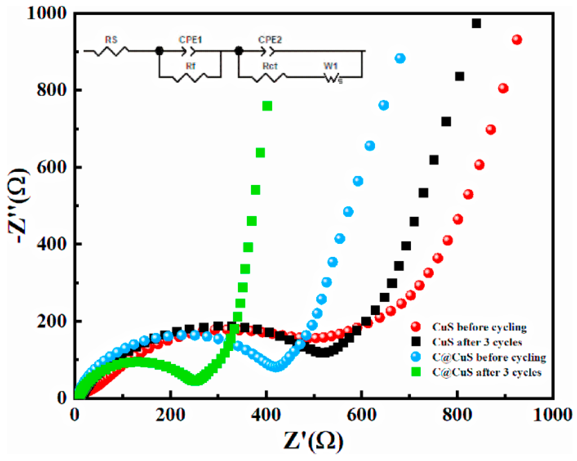
3.6. EIS Measurements

To further analyze the electrochemical properties, EIS measurements were conducted on the CuS nanoparticles and C@CuS electrodes before and after cycling, as shown in Figure 7. The impedance spectrum consists of a semicircle in the high-mid-frequency region and a slope line in the low-frequency region [42]. The semicircle represents the charge transfer resistance, while the slope line corresponds to a Warburg impedance associated with lithium-ion diffusion within the active material. Before cycling, the charge transfer resistance of the C@CuS composites is smaller than that of CuS. This trend remains after cycling. However, notable changes occur after three cycles: the charge transfer resistance of the C@CuS composite decreases, while that of CuS increases. This can be attributed to the decreased resistance of charge migration and the increased interfacial electrochemical reaction in the C@CuS composites [39].
The Li+ diffusion coefficient (DLi+) is an important physical parameter that characterizes the ability of lithium-ions to diffuse within the electrode material in LIBs. In general, a larger DLi+ represents a better high-current discharge capability and electrochemical performance. Based on EIS measurement data, the DLi+ of the CuS and the C@CuS are 1.04 × 10⁻¹⁵ and 7.79 × 10⁻¹⁵ cm2/s, respectively, after cycling for three cycles. The DLi+ of the C@CuS is seven times as high as that of CuS. In summary, the results of the EIS measurements align with the cycling performance and rate performance data, further evidencing the superior electrochemical characteristics of the C@CuS core–shell composite.

4. Conclusions

In this work, we have successfully synthesized a carbon-coated copper sulfide (C@CuS) core–shell framework utilizing a straightforward one-step precipitation method. The resulting composite material has demonstrated exceptional electrochemical performance, which can be attributed to the synergistic effects of the carbon core and CuS shell. The carbon core not only significantly improves the electrical conductivity of the active material but also effectively mitigates volume changes during the lithium intercalation and deintercalation processes. Furthermore, it prevents the agglomeration of CuS nanoparticles, thereby enhancing the overall electrochemical properties. The C@CuS core–shell composite has exhibited a remarkable cycle life, particularly at elevated current densities, along with superior rate performance. These characteristics make the C@CuS composite a highly promising anode material for lithium-ion batteries (LIBs), being especially suitable for applications requiring rapid charge/discharge capabilities and high energy storage. The innovative core–shell architecture and the simple synthesis approach presented in this study can be extended to the development of other metal sulfide-based materials. This offers a potential pathway to further improve the anode materials for next-generation LIBs. Our findings contribute to the advancement of LIB technology, providing a viable solution to meet the growing demands for high-performance energy storage systems.

Supplementary Materials

The following supporting information can be downloaded at https://www.mdpi.com/article/10.3390/jcs8090375/s1. Figure S1: The voltage-current curve of the samples; Figure S2: SEM image of CuS before (a) and after (b) 800 cycles at a current density of 1000 mA g−1; SEM image (c), and corresponding elemental mapping of Cu (d), S (e) of CuS after 800 cycles.

Author Contributions

Conceptualization, methodology, project administration, writing—original draft preparation, C.J.; software, validation, data curation, visualization, Z.P.; formal analysis, R.N.; investigation, Y.W.; resources, Z.Y.; supervision, Z.J.; funding acquisition, C.J. and Q.D.; writing—review and editing, Q.D. All authors have read and agreed to the published version of the manuscript.

Funding

This research was funded by the National Natural Science Foundation of China, grant number 11404251. The work at Ames National Laboratory was supported by the U.S. Department of Energy, Division of Materials Sciences and Engineering. Ames National Laboratory is operated for the U.S. Department of Energy by Iowa State University under Contract No. DE-AC02-07CH11358.

Data Availability Statement

The original contributions presented in the study are included in the article/Supplementary Material, further inquiries can be directed to the corresponding authors.

Conflicts of Interest

The authors declare no conflicts of interest.

References

  1. Lin, D.; Liu, Y.; Cui, Y. Reviving the lithium metal anode for high-energy batteries. Nat. Nanotechnol. 2017, 12, 194–206. [Google Scholar] [CrossRef] [PubMed]
  2. Zou, F.; Manthiram, A. A Review of the design of advanced binders for high performance batteries. Adv. Energy Mater. 2020, 10, 2002508. [Google Scholar] [CrossRef]
  3. Liu, W.; Song, M.S.; Kong, B.; Cui, Y. Flexible and stretchable energy storage: Recent advances and future perspectives. Adv. Mater. 2017, 29, 1603436. [Google Scholar] [CrossRef] [PubMed]
  4. Tong, L.; Wang, P.; Fang, W.; Guo, X.; Bao, W.; Yang, Y.; Shen, S.; Qiu, F. Interface engineering of Silicon/Carbon thin-film anodes for high-rate lithium-ion batteries. ACS Appl. Mater. Interfaces 2020, 12, 29242–29252. [Google Scholar] [CrossRef] [PubMed]
  5. Fan, Z.; Zheng, S.; He, S.; Ye, Y.; Liang, J.; Shi, A.; Wang, Z.; Zheng, Z. Preparation of micron Si@C anodes for lithium ion battery by recycling the lamellar submicron silicon in the kerf slurry waste from photovoltaic industry. Diam. Relat. Mater. 2020, 107, 107898. [Google Scholar] [CrossRef]
  6. Nguyen, T.X.; Patra, J.; Chang, J.-K.; Ting, J.-M. High entropy spinel oxide nanoparticles for superior lithiation–delithiation performance. J. Mater. Chem. A 2020, 8, 18963–18973. [Google Scholar] [CrossRef]
  7. Agostini, M.; Hwang, J.Y.; Kim, H.M.; Bruni, P.; Brutti, S.; Croce, F.; Matic, A.; Sun, Y.K. Minimizing the Electrolyte Volume in Li–S Batteries: A Step Forward to High Gravimetric Energy Density. Adv. Energy Mater. 2018, 8, 1801560. [Google Scholar] [CrossRef]
  8. Maroni, F.; Bruni, P.; Giuli, G.; Brutti, S.; Croce, F. Electrospun Carbon/CuxO Nanocomposite material as Sustainable and High Performance Anode for Lithium-Ion Batteries. ChemistryOpen 2019, 8, 781–787. [Google Scholar] [CrossRef]
  9. Geng, P.; Zheng, S.; Tang, H.; Zhu, R.; Zhang, L.; Cao, S.; Xue, H.; Pang, H. Transition metal sulfides based on graphene for electrochemical energy storage. Adv. Energy Mater. 2018, 8, 1703259. [Google Scholar] [CrossRef]
  10. Lim, Y.V.; Li, X.L.; Yang, H.Y. Recent tactics and advances in the application of metal sulfides as high-performance anode materials for rechargeable sodium-ion batteries. Adv. Funct. Mater. 2020, 31, 2006761. [Google Scholar] [CrossRef]
  11. Theerthagiri, J.; Senthil, R.A.; Nithyadharseni, P.; Lee, S.J.; Durai, G.; Kuppusami, P.; Madhavan, J.; Choi, M.Y. Recent progress and emerging challenges of transition metal sulfides based composite electrodes for electrochemical supercapacitive energy storage. Ceram. Int. 2020, 10, 14317–14345. [Google Scholar] [CrossRef]
  12. Zhao, J.; Zhang, Y.; Wang, Y.; Li, H.; Peng, Y. The application of nanostructured transition metal sulfides as anodes for lithium ion batteries. J. Energy Chem. 2018, 27, 1536–1554. [Google Scholar] [CrossRef]
  13. Jiang, K.; Chen, Z.; Meng, X. CuS and Cu2S as cathode materials for lithium batteries: A Review. ChemElectroChem 2019, 6, 2825–2840. [Google Scholar] [CrossRef]
  14. Lai, C.-H.; Huang, K.-W.; Cheng, J.-H.; Lee, C.-Y.; Hwang, B.-J.; Chen, L.-J. Direct growth of high-rate capability and high capacity copper sulfide nanowire array cathodes for lithium-ion batteries. J. Mater. Chem. A 2010, 20, 6638–6645. [Google Scholar] [CrossRef]
  15. Jing, P.; Wang, Q.; Wang, B.; Gao, X.; Zhang, Y.; Wu, H. Encapsulating yolk-shell FeS2@carbon microboxes into interconnected graphene framework for ultrafast lithium/sodium storage. Carbon 2020, 159, 366–377. [Google Scholar] [CrossRef]
  16. Cheng, J.; Pan, Y.; Zhu, J.; Li, Z.; Pan, J.; Ma, Z. Hybrid network CuS monolith cathode materials synthesized via facile in situ melt-diffusion for Li-ion batteries. J. Power Sources 2014, 257, 192–197. [Google Scholar] [CrossRef]
  17. Chen, Y.; Li, J.; Lei, Z.; Huo, Y.; Yang, L.; Zeng, S.; Ding, H.; Qin, Y.; Jie, Y.; Huang, F.; et al. Hollow CuS nanoboxes as Li-Free cathode for high-rate and long-life lithium metal batteries. Adv. Energy Mater. 2020, 10, 1903401. [Google Scholar] [CrossRef]
  18. Iqbal, S.; Bahadur, A.; Saeed, A.; Zhou, K.; Shoaib, M.; Waqas, M. Electrochemical performance of 2D polyaniline anchored CuS/Graphene nano-active composite as anode material for lithium-ion battery. J. Colloid Interface Sci. 2017, 502, 16–23. [Google Scholar] [CrossRef]
  19. Li, H.; Wang, Y.; Huang, J.; Zhang, Y.; Zhao, J. Microwave-assisted synthesis of CuS/Graphene composite for enhanced lithium storage properties. Electrochim. Acta 2017, 225, 443–451. [Google Scholar] [CrossRef]
  20. Wang, W.; Yang, Y.; NuLi, Y.; Zhou, J.; Yang, J.; Wang, J. Metal organic framework (MOF)-derived carbon-encapsulated cuprous sulfide cathode based on displacement reaction for hybrid Mg2+/Li+ batteries. J. Power Sources 2020, 445, 227325. [Google Scholar] [CrossRef]
  21. Li, L.; Liu, Y.; Han, Y.; Qi, X.; Li, X.; Fan, H.; Meng, L. Metal-organic framework-derived carbon coated copper sulfide nanocomposites as a battery-type electrode for electrochemical capacitors. Mater. Lett. 2019, 236, 131–134. [Google Scholar] [CrossRef]
  22. Wang, P.; Shen, M.; Zhou, H.; Meng, C.; Yuan, A. MOF-derived CuS@Cu-BTC composites as high-performance anodes for lithium-ion batteries. Small 2019, 15, 1903522. [Google Scholar] [CrossRef]
  23. Wang, Y.; Zhang, Y.; Li, H.; Peng, Y.; Li, J.; Wang, J.; Hwang, B.-J.; Zhao, J. Realizing high reversible capacity: 3D intertwined CNTs inherently conductive network for CuS as an anode for lithium ion batteries. Chem. Eng. J. 2018, 332, 49–56. [Google Scholar] [CrossRef]
  24. Zhang, J.; Zhao, Y.; Zhang, Y.; Li, J.; Babaa, M.R.; Liu, N.; Bakenov, Z. Synthesis of microflower-like vacancy defective copper sulfide/reduced graphene oxide composites for highly efficient lithium-ion batteries. Nanotechnology 2019, 31, 095405. [Google Scholar] [CrossRef]
  25. Hwa, Y.; Zhao, J.; Cairns, E.J. Lithium sulfide (Li2S)/graphene oxide nanospheres with conformal carbon coating as a high-rate, long-life cathode for Li/S cells. Nano Lett. 2015, 15, 3479–3486. [Google Scholar] [CrossRef] [PubMed]
  26. Li, X.; Wang, H.; Zhang, W.; Feng, Y.; Ma, J. S-doped carbon-coated FeS2/C@C nanorods for potassium storage. Acta Metall. Sin-Engl. 2020, 34, 321–328. [Google Scholar] [CrossRef]
  27. Li, X.; He, X.; Shi, C.; Liu, B.; Zhang, Y.; Wu, S.; Zhu, Z.; Zhao, J. Synthesis of one-dimensional copper sulfide nanorods as high-performance anode in lithium ion batteries. ChemSusChem 2014, 7, 3328–3333. [Google Scholar] [CrossRef]
  28. Xu, X.; Li, L.; Chen, H.; Guo, X.; Zhang, Z.; Liu, J.; Mao, C.; Li, G. Constructing heterostructured FeS2/CuS nanospheres as high rate performance lithium ion battery anodes. Inorg. Chem. Front. 2020, 7, 1900–1908. [Google Scholar] [CrossRef]
  29. Ding, C.; Su, D.; Ma, W.; Zhao, Y.; Yan, D.; Li, J.; Jin, H. Design of hierarchical CuS/graphene architectures with enhanced lithium storage capability. Appl. Surf. Sci. 2017, 403, 1–8. [Google Scholar] [CrossRef]
  30. Zhou, M.; Peng, N.; Liu, Z.; Xi, Y.; He, H.; Xia, Y.; Liu, Z.; Okada, S. Synthesis of sub-10nm copper sulphide rods as high-performance anode for long-cycle life Li-ion batteries. J. Power Sources 2016, 306, 408–412. [Google Scholar] [CrossRef]
  31. Li, S.; Ge, P.; Jiang, F.; Foster, C.W.; Banks, C.E.; Xu, W.; Zhang, Y.; Hong, W.; Zhang, C.; Sun, W.; et al. Molecular-level CuS@S hybrid nanosheets constructed by mineral chemistry for energy storage systems. ACS Appl. Mater. Interfaces 2018, 10, 43669–43681. [Google Scholar] [CrossRef] [PubMed]
  32. Feng, C.; Zhang, L.; Yang, M.; Song, X.; Zhao, H.; Jia, Z.; Sun, K.; Liu, G. One-pot synthesis of copper sulfide nanowires/reduced graphene oxide nanocomposites with excellent lithium-storage properties as anode materials for lithium-ion batteries. ACS Appl. Mater. Interfaces 2015, 7, 15726–15734. [Google Scholar] [CrossRef] [PubMed]
  33. Zhang, S.; Ying, H.; Huang, P.; Wang, J.; Zhang, Z.; Yang, T.; Han, W.Q. Rational design of pillared SnS/Ti3C2Tx MXene for superior lithium-ion storage. ACS Nano 2020, 14, 17665–17674. [Google Scholar] [CrossRef] [PubMed]
  34. Wang, S.; Ning, P.; Huang, S.; Wang, W.; Fei, S.; He, Q.; Zai, J.; Jiang, Y.; Hu, Z.; Qian, X.; et al. Multi-functional NiS2/FeS2/N-doped carbon nanorods derived from metal-organic frameworks with fast reaction kinetics for high performance overall water splitting and lithium-ion batteries. J. Power Sources 2019, 436, 226857. [Google Scholar] [CrossRef]
  35. Chen, Q.; Chen, W.; Ye, J.; Wang, Z.; Lee, J.Y. l-Cysteine-assisted hydrothermal synthesis of nickel disulfide/graphene composite with enhanced electrochemical performance for reversible lithium storage. J. Power Sources 2015, 294, 51–58. [Google Scholar] [CrossRef]
  36. Hu, Q.; Meng, Y.; Zhang, H.; Zhao, G.; Hu, J.; Zhu, F.; Zhang, Y. Encapsulated Ni3S2 nanoparticles with N, S dual-doped carbon nanotubes: A robust structure for lithium storage. J. Electroanal. Chem. 2020, 873, 114383. [Google Scholar] [CrossRef]
  37. Pi, W.; Mei, T.; Li, J.; Wang, J.; Li, J.; Wang, X. Durian-like NiS2@rGO nanocomposites and their enhanced rate performance. Chem. Eng. J. 2018, 335, 275–281. [Google Scholar] [CrossRef]
  38. Xu, X.; Ji, S.; Gu, M.; Liu, J. In situ synthesis of MnS hollow microspheres on reduced graphene oxide sheets as high-capacity and long-life anodes for Li- and Na-ion batteries. ACS Appl. Mater. Interfaces 2015, 7, 20957–20964. [Google Scholar] [CrossRef]
  39. Wang, R.; Li, B.; Lai, L.; Hou, M.; Gao, J.; Wu, R. 3D urchin-like architectures assembled by MnS nanorods encapsulated in N-doped carbon tubes for superior lithium storage capability. Chem. Eng. J. 2019, 355, 752–759. [Google Scholar] [CrossRef]
  40. Liu, H.; Wei, C.; Ai, Z.; Li, M.; Xu, M.; Ma, C.; Shi, J. The positive effect of 3D interpenetrating network porous structure by carbon membranes on alleviating the volume expansion of SnS2 nanosheets for enhancing lithium and sodium storage. Colloids Surf. B 2021, 610, 125937. [Google Scholar] [CrossRef]
  41. Xu, Q.-T.; Xue, H.-G.; Guo, S.-P. FeS2 walnut-like microspheres wrapped with rGO as anode material for high-capacity and long-cycle lithium-ion batteries. Electrochim. Acta 2018, 292, 1–9. [Google Scholar] [CrossRef]
  42. Lazanas, A.C.; Prodromidis, M.I. Electrochemical Impedance Spectroscopy—A Tutorial. ACS Meas. Sci. Au 2023, 3, 162–193. [Google Scholar] [CrossRef] [PubMed]
Figure 1. XRD patterns (a) and Raman spectra (b) of CuS nanoparticles and C@CuS composite. The peaks labelled D and G in (b) represent the D and G bands of carbon.
Jcs 08 00375 g001
Figure 2. TEM images of C45 (a), CuS nanoparticles (b), C@CuS composite (c); HR-TEM and SAED image of the C@CuS (d); SEM image (e) and corresponding elemental mapping of Cu (f), S (g) and C (h) of the C@CuS.
Jcs 08 00375 g002
Figure 3. CV curves of C@CuS composite (a) and CuS nanoparticles (b); discharge/charge curves of C@CuS composite (c) and CuS nanoparticles (d).
Jcs 08 00375 g003
Figure 4. (a) Cycling performance of the C@CuS composite and CuS nanoparticles at 100 mA g−1; (b) long cycling performance of the C@CuS composites and CuS nanoparticles at 1000 mA g−1.
Jcs 08 00375 g004
Figure 5. (a) Rate capabilities of the C@CuS composite and CuS nanoparticles electrodes for Li-ion storage at different current densities; galvanostatic discharging/charging curves at different current densities of the C@CuS composite (b) and CuS nanoparticles (c).
Jcs 08 00375 g005
Figure 6. SEM image of C@CuS before (a) and after (b) 800 cycles at a current density of 1000 mA g−1; SEM image (c), and corresponding elemental mapping of Cu (d), S (e) and C (f) of CuS after 800 cycles.
Jcs 08 00375 g006
Figure 7. EIS spectra of C@CuS composite and CuS nanoparticles before and after cycling.
Jcs 08 00375 g007
Table 1. Cycling performances of CuS-based electrodes as anode materials for LIBs.
Electrode MaterialsInitial Discharge Capacity (mAh g−1)Discharge Capacity (mAh g−1)Current Density (mA g−1)Refs.
CuS nanorods735390 (250 cycles)112[30]
CuS nanorods550472 (100 cycles)100[27]
CuS monolith310468 (100 cycles)112[16]
CuS/2.5%CNT430558 (100 cycles)400[23]
Vs-CuS/rGO882500 (100 cycles)112[24]
513 (450 cycles)500
CuS@S790513.2 (200 cycles)100[31]
402 (200 cycles)1120
CuS-GO625497 (100 cycles)200[19]
348 (1000 cycles)2000
CuS NWs/rGO908620 (100 cycles)280[32]
320 (430 cycles)2240
C@CuS1108811 (100 cycles)100this work
463 (800 cycles)1000
Disclaimer/Publisher’s Note: The statements, opinions and data contained in all publications are solely those of the individual author(s) and contributor(s) and not of MDPI and/or the editor(s). MDPI and/or the editor(s) disclaim responsibility for any injury to people or property resulting from any ideas, methods, instructions or products referred to in the content.

