Article

Interdisciplinary Analysis of Roman Floor Types in the Villa of Diomedes in the Archaeological Park of Pompeii

by
Giuseppina De Martino
1,
Marco Di Ludovico
1,*,
Hélène Dessales
2 and
Andrea Prota
1
1
Department of Structures for Engineering and Architecture, University of Naples Federico II, 80125 Naples, Italy
2
Ecole Normale Supérieure, AOrOC-UMR 8546, CNRS-PSL, 75005 Paris, France
*
Author to whom correspondence should be addressed.
Heritage 2023, 6(7), 5559-5582; https://doi.org/10.3390/heritage6070293
Submission received: 26 June 2023 / Revised: 14 July 2023 / Accepted: 18 July 2023 / Published: 23 July 2023
(This article belongs to the Section Archaeological Heritage)

Abstract

:
The present work presents and discusses an analysis of the floor types of the Villa of Diomedes (Pompeii archaeological park in the Campania region, Italy) from an architectural, archaeological, and structural point of view. In particular, the geometrical-structural parameters of different floor types and the rules used by ancient builders to design them are investigated by means of interdisciplinary research. The links between structural assumptions, archival sources, geometric survey, in situ visual inspections, and archaeological information make it possible to define the geometrical-structural parameters of eleven barrel vaults, three wooden floors, and three sloped wooden roofs (buried and collapsed during the Vesuvius eruption). A specific study of the barrel vaults is presented to investigate the relationships between the structural parameters of the main vaults. Furthermore, a comparison between the vaults’ dimensions obtained from surveys and those produced by formulations in the literature between the 15th and 20th centuries concerning masonry vault designs is presented and discussed. These analyses, carried out within the framework of the Villa of Diomedes interdisciplinary project, were very useful for interpreting the fabrication of the villa and making a 3D reconstruction model of how the villa probably looked in the fateful year of 79 A.D.

1. Introduction

If historical and architectural heritage constructions are to be protected and safeguarded for today’s communities and future generations, their conservation, maintenance, and restoration should comply with principles of authenticity and material compatibility [1]. Any conservation project therefore clearly needs to adopt an interdisciplinary knowledge approach to acquire historical data, perform a detailed analysis of the construction techniques adopted, and define any modifications that occurred over a building’s lifetime [2,3]. The study of floor types (arches, vaults, and wood beams) in the field of historical and cultural heritage constructions is often missing due to the lack of detailed information on such structures, especially in the case of ruins. Thus, the study of such components, which play a crucial role in the analysis of the structural behavior of constructions, is particularly fascinating, but also very complex. It involves investigation of the ancient design criteria and raw materials used in the past, as well as the cross-linking of different sources of data, combining different fields like archaeology, architecture, geology, topography, the conservation sciences, and structural engineering.
Cultural heritage documentation research, based on the investigation of available archival sources, is one of the key tasks within the knowledge process framework. Archival sources provide information on excavated remains and the interventions carried out on them up to the present day. The analysis of standing buildings at archaeological sites requires refined methods that use accurate investigations of archival sources and in situ surveys. This enables researchers to acquire fundamental information on the construction methods and practices used by ancient builders. This step is crucial for defining the type of intervention and relevant materials to be used in a conservation, maintenance, restoration, or partial reconstruction process.
Roman architecture used arches extensively, with large ashlars of stones or bricks arranged radially with thin mortar joints. Concrete is also used for the vaults; the Pompeii archaeological park concrete vaults were first detected in the Stabian Baths, built around the second half of the second century B.C. [4,5,6,7,8,9,10]. This technique was used to create a simple geometric shape with a structural behavior resembling a monolith [4,11]. Several approaches were adopted over time to improve their structural performance. Starting from the first century A.D., Roman builders added brick ribs to vaults composed of rubble and mortar masonry to avoid the cracking that would have otherwise occurred [4]. Furthermore, they arranged materials according to their unit weight: stone blocks and tiles for the lower parts and light, inert conglomerate for the upper sections. They then also produced lightweight vaults using empty amphorae [12,13]. The first examples of amphorae in the vaults occur in the second century (i.e., Magazzini Traianei and Villa alla Vignaccia). They were initially used to save on construction materials. The frequent use of amphorae for lightening vaults can be found in the Minerva Medica temple (first half of the fourth century A.D.) [11,12,14].
Ancient builders improved their competence over time by way of trial and error [4,10]. This enabled them to define some ‘rules of thumb’ based on the geometrical relationships between vault components, e.g., span, rise, and crown thickness and the width and height of piers. Nowadays, such rules have almost been forgotten, in relation to the design of floor types [5].
The first tenet only appeared in Renaissance treatises [15] and only concerned the abutment widths of Gothic structures [16]. Rules were used extensively in the 18th century to validate new theories related to arch stability [17,18]. In this period, static analyses based on wedge theory were applied to the field thanks to the work of de la Hire and others [19]. After the studies described in [19,20,21,22], the methods used to investigate the structural behavior of vaulted buildings were essentially based on geometric proportions. However, their structural forms continued to be established using various rules of thumb, because builders lacked the knowledge of mathematics and mechanics required to understand and perform static analyses [23].
Roman builders made extensive use of masonry vaults but often preferred wooden structures for floors and roofs due to their high strength-to-weight ratio [24]. Two main typologies of wooden floors were used in Roman times and described by Vitruvius in De architectura in the first century B.C.: (i) contignatio and contabulatio (or coaxatio), made of a single or double layer of beams and wooden planks; and (ii) lacunar (or laquear), made of two perpendicular rows of beams. The name contignatio came from the Roman word ‘tignum’ (beam) and referred to the wooden structure, while contabulatio (or coaxatio) refers to a wooden floorboard, sometimes made of two layers (coaxatio transversa) to obtain a stiffer structure. Lacunar was used to cover large areas (span longer than 5 m) or to serve a decorative purpose, creating a coffered ceiling [5,6,24].
Different evidence of wooden floors was found in ancient Roman cities in Campania, which in several cases were made according to Vitruvius’ instructions [5,6,24,25]. The cross-sections of the beams were either circular, sometimes accomplished using rough, lengthwise-cut logs, or rectangular [24]. Beams were generally positioned orthogonally to the walls, in the direction of the smallest side of the area to be covered. Spans were generally quite short, i.e., not exceeding 4.50 m in length, probably because shorter beams were more easily procured, less expensive, and easier to handle [24]. The beams were generally positioned at a constant distance, with the spacing computed as a function of the cross-sectional dimensions, the span, and the bearing load. Evidence in the Pompeii and Herculaneum archaeological parks shows that ancient floors were very rigid due to their short spans and large cross-sections. According to different surveys performed at the Pompeii and Herculaneum archaeological parks, the beam spacing generally varied from about 30 cm to about 45 cm, while beam sockets varied from about a minimum of 12 cm to a maximum of 34 cm [5,6,24,25].
Vitruvius also discussed the type of timbers available for construction [26]. A first classification of the wood from different trees according to density, heaviness, and hardness was provided by Theophrastus (Book 5 of Historia Plantarum). Pliny provided additional evidence of the use of wood, focusing on woodworking.
This paper focuses on the floor types surveyed in the Villa of Diomedes (Pompeii archaeological park in the Campania region, Italy). The study aimed to clarify and understand the technical choices made by ancient builders when designing such structural members. The study was carried out within the framework of the Villa of Diomedes multidisciplinary project, which is coordinated by the Ecole Normale Supérieure—PSL University (UMR 8546), with the support of the Centre Jean Bérard (Naples, Ecole Française de Rome—CNRS), the INRIA (Institut National de Recherche en Informatique et Automatique, Center de Paris-Rocquencourt), and the Pompeii archaeological park [27]. The project was launched in 2012 to restore the Villa of Diomede’s full history, from its initial construction as a Roman villa to its modern state. Identification and modelling of the many construction techniques that characterized its existence up until the eruption of Vesuvius in 79 A.D., as well as the restorations that changed it from the end of the eighteenth century to today, have been required. Different research profiles have been involved to fill this purpose, including the history of excavations and restorations, construction archaeology, databases, geographic information system, geophysics, structural engineering, scientific imaginary, and 3D modelling.
In 2014, the Villa of Diomede project became part of the ANR RECAP program, completed in 2019 (RECAP: rebuilding after an earthquake: ancient experiences and innovations in Pompeii), to investigate the impact of the 62–63 A.D. earthquake and propose relevant repair interventions and possible innovative construction techniques to avoid seismic risk. In recent years, other studies on the Archeological Park of Pompeii have involved the investigation of other structural members such as masonry walls and columns [28,29].
This paper focuses on the analysis of floor types in the Villa of Diomedes. In particular, Section 2 describes the villa and its historical evolution, Section 3 discusses the interdisciplinary knowledge process, while Section 4 presents the floor identification’s methodology to investigate on the most significant parameters of the horizontal structures. Finally, Section 5 presents an analysis of the floor types, discusses the data collected from 19 horizontal structures, and presents a comparison of their characteristics and those retrieved using literature design (i.e., conducted between the 15th and the 20th centuries) formulations. We also discuss the wooden floor characteristics to investigate beam dimensions and to determine the criteria adopted by Roman builders when designing such structural members. This allowed us to frame the analysis of floor types within an overall assessment of the villa from an archaeological and architectural engineering point of view. This study may significantly contribute to the knowledge of floor types and provides a useful tool for technicians involved in analyzing and understanding the structural behavior of ruins.

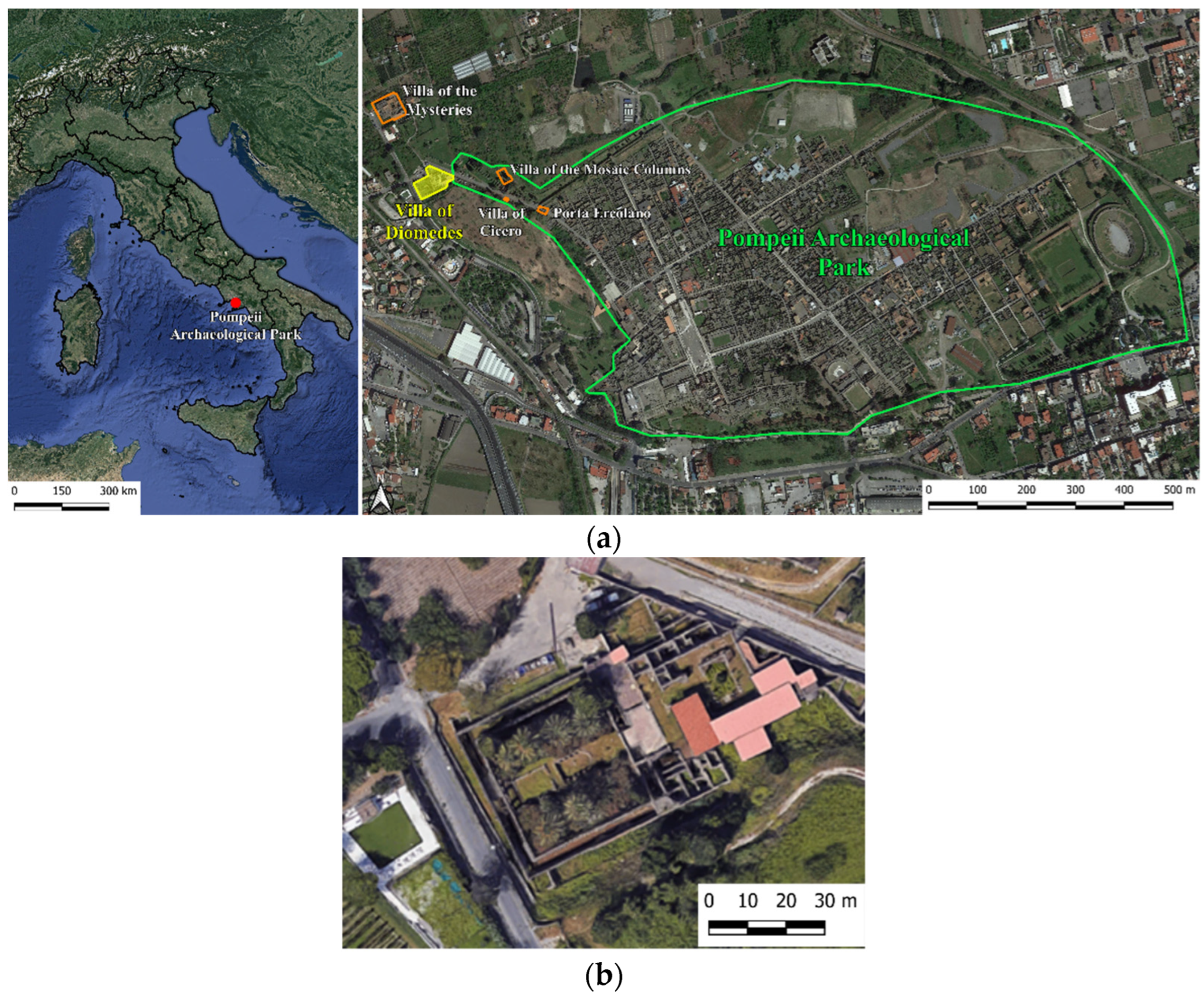
2. Historical Notes and Description of the Villa of Diomedes (Pompeii Archaeological Park)

The Villa of Diomedes is located in the northwest area (the so-called ‘suburban area’, 200 m north of the Herculaneum Gate) of the Pompeii archaeological park in the Campania region (Figure 1). Three other villas are located in the area: the Villa of Cicero, the Villa of the Mosaic Columns, and the Villa of the Mysteries. The four villas are connected by Sepulchres Street, which starts at Porta Ercolano and ends at the Villa of the Mysteries. Studies on the urban context have highlighted that the three villas—the Villa of Diomedes, the Villa of Cicero, and the Villa of the Mysteries—are arranged along a parallel axis in the north–south and east–west directions [30,31]. On the other hand, the orientation of Sepulchres Street does not correspond with this axis. Therefore, it seems that the construction of the street is posterior to the construction of the three villas. This hypothesis is also supported by several archaeological studies. These studies highlighted the closure of a door on Mercurius Street and the simultaneous opening of Porta Ercolano once Sepulchres Street was built. The urban evolution of the city is discussed in [32]. According to [32], the urban reorganization could be justified by the logic of a deep political and institutional mutation, such as the period of the deduction of the syllanienne colony. Even if this hypothesis seems very truthful, it remains very difficult to determine the transformations suffered by the Villa of Diomedes after the construction of Sepulchres Street.
The villa was one of the first buildings discovered in Pompeii during the excavation campaigns carried out between 1771 and 1775, and it was one of the largest private constructions found there. Initially known as the “suburban Villa”, it owes its current name to the tomb of Marcus Arrius Diomedes, which was discovered in 1774 close to the villa’s entrance. The current configuration of the villa is a consequence not only of its complex alterations over time [27], but also the damage that occurred after the 79 A.D. Vesuvius eruption that completely covered the ancient city of Pompeii.
Nowadays, the villa consists of three levels (Figure 2): (i) the ground, (ii) the garden, and (iii) the cryptoporticus. It is possible to gain access through the monumental entrance on Sepulchres Street. As is typical of Roman villas, the peristyle can be reached via the monumental entrance. There is a triangular portico with a frigidarium and a kitchen on the east side of the peristyle, while the residential rooms and the apsed room reside on the south side, and the tablinum is on the west side.
The Vesuvius eruption led to the collapse of the terrace that was built as the roof for the four-sided portico surrounding the garden. There are servile rooms on the north side of the peristyle, while two staircases located on the north and south sides of the ground level allow access to the garden level. The garden level is comprised of vaulted rooms on the east side and a four-sided portico that encloses the garden. The triclinium is in the center of the garden.

3. The Interdisciplinary Knowledge Process

An interdisciplinary knowledge process was carried out for the Villa of Diomedes to evaluate the building from both technical-scientific and historical-critical points of view. The main problem faced in collecting knowledge of historic building refers to the difficulties in retracing the evolution of the building during its life cycle. Therefore, accurate historical research, geometrical-architectural and structural surveys, and the detection of damage and structural criticalities are crucial steps necessary to perform refined analyses and interpretation of historical building techniques. Structural engineering has proven to be a good technical support to the notions acquired on the field by archaeologists, as it allows for the ancient design criteria of ancient Roman art to be re-read using scientific methods and for the technical value of “traditional” materials to be evaluated.
The starting point for this study was the creation of a digital model of the villa in its current state [33]. In 2013, drone photographic surveys were carried out. The images were taken at different scales: from a high altitude to see the whole villa and its surroundings, and from a lower altitude to see all the uncovered areas. All the images were processed by the company Iconem using PMVS software, developed by Jean Ponce (Willow team, ENS) and Yasutaka Furukawa (University of Illinois, Champaign, IL, USA), to reconstruct a precise 3D photogrammetric model of the villa. This was used in conjunction with software, such as the Bundler free software from the University of Washington and Apero of National Geographic, to calibrate the photographic devices (to calculate their intrinsic parameters and positions).
Thanks to additional photography, the 3D photogrammetric model was completed and refined in 2015 by Alban-Brice Pimpaud. A topographical survey was also carried out to draw the plan of the villa on a scale of 1:50. An overall model of the villa was realized in its topographical context. This makes it possible to visualize the villa in its environment and to georeference it in the context of a geographic information system (GIS) [34].
Starting-form 3D photogrammetric model axonometric projections of the state of the Villa of Diomedes in the present day, (i.e., ruins) were created (Figure 3).
Having defined the villa from geometric point of view, the first step of the interdisciplinary knowledge process involved a comprehensive approach to the knowledge of the building by means of in-situ visual inspections supported by historical documentary sources, such as historical photographs and perspective views, plans, and cross-sections from 19th-century architects. The existing architectural structures were studied using both archaeology of construction and structural engineering methods. Several in situ inspections together with non-destructive tests were carried out to establish a shared technical-scientific and historical-critical path. The achievement of a detailed knowledge level and an accurate information useful for structural analyses performed according to current standards requirement reported in [2,3] were obtained. The knowledge acquired was enriched by research on the historical archives of Museo Archeologico Nazionale di Napoli, MANN, and Palazzo Caramanico in the Reggia di Portici.
Furthermore, in the second stage, the building itself was assumed as an historical document. Therefore, the Villa of Diomedes was analyzed as a “material culture” by means of the method of archaeological reading used in conjunction with the graphic and photographic survey of the building. Ground-penetrating radar measurements were carried out on some of the internal and external parts of the Villa of Diomedes and outside its perimeter. The outcome revealed the traces of probable earlier structures, as reported in [35].
The analysis of the villa as a material culture along with the study of building techniques, paintings styles, and structural cracking allowed us to identify six construction phases [27].
Other repair, restoration, and maintenance interventions were carried out during and after the excavations up to the present day. During the excavation, the building was maintained in the state of discovery, with only repair and consolidation interventions being carried out, as reported in the journal of excavation [36]. After excavation, several interventions were carried out due to the need for simple maintenance or to reconstruct the collapsed portion of the building [37]. An important restoration occurred in 19461, after a US bombardment affected the southern perimeter wall of the buildings. Finally, starting in 2020, the PAP launched a project to restore the monument as part of the Grande Progetto Pompei [38].
At the end of the interdisciplinary knowledge process, about 200 historical photographs and perspective views, plans, and cross-sections from 19th century architects, together with data acquired during the in-situ survey, were then projected as a series of interpretive layers in the 3D model. The registration of photographs and perspective views was achieved using the Blender camera calibration toolkit (BLAM).
The studies carried out showed evidence of architectural elements that no longer exist. For example, in Figure 4a, there is evidence of wooden floors (beams holes highlighted with red box) and stairs (highlighted with red line).
Based on this evidence and the data acquired using the interdisciplinary knowledge process, it has been hypothesized that the configuration before the 79 A.D. eruption included wooden floors, a staircase, and the upper part of the wall. The configuration is highlighted in red in Figure 4b.
Similar studies were carried out on the whole villa to design the 3D model of the villa as it probably would have looked during the fateful year of 79 A.D when the Vesuvius eruption buried the ancient Roman city of Pompeii under a thick carpet of volcanic ash. This was realized using AutoCAD software, and a simplified 3D model of the Diomedes Villa was produced. An initial crucial step was undertaken to begin the 3D modelling: the evaluation of the quote of the horizontal structure. To this aim, topographical measurements carried out in 2015 by the architect G. Chapelin as part of the “Grande Progetto Pompei” [39] were used. The procedure led to some difficulties since the topographical points are related to the sea level, but in some areas, the measurements are related to the quote to which the excavation has been stopped instead of the real quote. Therefore, to reach a reliable outcome, it was necessary to integrate the information of the topographical measurement with the historical sources and to do a continuous comparison with the archaeological studies. Different levels of precision and reliability were used. Generally, reconstruction presents a high degree of uncertainty because the data related to the modern renovation phase of the villa should be carefully detected and excluded, while parts that are no longer visible (i.e., the first floor, the horizontal covering structures of the ground floor, and the towers on south and north sides of the four-sided portico in the Villa of Diomedes) should be defined and correctly inserted in the actual configuration. In cases where a 3D model reflects a constructive hypothesis, it is advisable to use a scale of historical-archaeological evidence for its representation [40].
The 3D model of the villa as it probably would have looked during the fateful year of 79 A.D is reported in Figure 5.

4. Floor Identification Methodology

A specific study of floor types was carried out in the present study. The 3D photogrammetric model, together with field surveys and post field analyses, allowed us to identify the main geometrical-structural parameters of the floor types of the villa and understand their structural behavior [2,3]. In the case of rooms without floor and/or evidence of beams holes, it was possible to hypothesize that the original vaults probably collapsed due to the weight of the pyroclastic material deposited following the 79 A.D. eruption. Unfortunately, there are no traces or information about their failure mode.
The following sections illustrate the methodology adopted to identify the floor types and relevant geometrical-structural parameters.

4.1. Vaults

In situ surveys were required to identify the geometrical-structural parameters of the villa’s vaults. To this end, data from geometrical surveys and topographical measurements were integrated with historical sources [41,42,43,44] and evidence from archaeological studies. It is not always easy to identify floor types using only visual inspections. Indeed, in relation to vaults, different cases can be found in the ruins of archaeological sites in general (Figure 2): (a) undamaged vault; (b) undamaged vault in a room that has not been fully excavated; (c) partially collapsed vault; (d) collapsed vault. In some cases, geometrical-structural data in relation to vaults can be entirely derived from in situ surveys, with or without the support of orthoimages and topographical data. A typical example of the case seen in Figure 6a in the Villa of Diomedes is set out in Figure 7. The data produced by a geometrical survey of the vaults in their current condition were validated using orthoimages (Figure 7(a1)) and archival sources (Figure 7(a2)). This made it possible to achieve the complete restitution of the villa’s geometrical-structural parameters (Figure 7(a3)).
An example of the case seen in Figure 6b was found in the villa on the cryptoporticus level. As a result of an incomplete excavation, it was not possible to directly determine the distance between the vault intrados and the floor level. According to data retrieved from the topographical features, it was possible to conclude that the excavation work ended at different levels of the villa’s cryptoporticus level (Figure 7(b1,b2)). It was possible to establish the actual floor level based on the number of stairs in the two staircases that enabled access to the cryptoporticus and the topographical survey data on the floor levels above sea level (a.s.l.).
In detail, the planking level was chosen as the last step of the stairway leading from the cryptoporticus to room No. 74 (Figure 2). It was believed that this level was more precise than the one of the staircases in room No. 48 (Figure 2). A little bit of in-place surface cleaning revealed a couple of stairs that has been previously hidden by deposit soil.
As a result, by cross-linking the information sources using geometrical survey and topographical data and by adding the information provided by orthoimages, it was possible to determine the geometrical-structural parameters of the vault (Figure 7(b3)).
A partially collapsed vault (i.e., the case seen in Figure 6c) was found on the garden level. In this case, it was not possible to measure the distance between the floor and the intrados of the vault keystone, either in situ or from the archival sources [42,43,44]. However, it was possible to determine the vault’s geometrical-structural parameters (Figure 7(c2)) using a graphical construction based on the information provided by the orthoimage (Figure 7(c1)) of the remaining part of the vault (i.e., the ruins of the collapsed vault).
Finally, a collapsed vault (i.e., the case seen in Figure 6d) was also detected in the villa on the ground level. In this case, a trace of curved plaster and the presence of holes on an orthogonal wall (Figure 7(d1)) enabled us to assume the existence of a false vault and an original horizontal structure comprised of wooden beams. This assumption was validated by an analysis of the available archival sources, as set out in (Figure 7(d2)). These information sources made it possible to define the geometrical parameters of the false vault (Figure 7(d3)), which had no structural function.

4.2. Wooden Floors

In situ surveys are the first stage in seeking to identify the geometrical-structural parameters of wooden floors. For this, the data provided by visual inspections and archival sources and the evidence provided by archaeological studies are crucial. Ancient wooden structures in Pompeii collapsed and were buried due to the Vesuvius eruption. Nevertheless, traces of wooden floors and sloped wooden roofs are still noted in in situ surveys [45]. Indeed, rows of rectangular holes in walls to support floor beams can be detected by visual inspection in several buildings. The definition of beams’ cross-sectional dimensions is, however, a challenging task. Although Roman builders commonly used rectangular cross-sections, carbonized wooden beam ruins and imprint evidence at the archaeological park of Herculaneum have demonstrated that circular beams were often used and placed in rectangular holes [4,24]. Furthermore, the holes were larger than the minimum needed to ensure support for the beams for the following reasons [13]: (a) because a gap between the beam and the masonry was required to ensure beneficial ventilation and avoid the generation of condensation at the wood masonry interface; (b) because the holes were also used to host temporary structures used in the construction phases; and (c) due to installation procedure requirements. It was only possible to establish the actual beam dimensions in traces of conglomerate.
The top layer of a structure may be either a simple wooden floor or a thick pack consisting of conglomerate screed and a stone or brick pavement. A screed was made of several layers depending on the function of the structure: as an intermediate level or a planar roof. As reported in De Architectura, Liber Septimus 1, 2, 3, it was necessary to apply a layer of ferns (filex) or straw (palea) over the timber planks before laying the conglomerate to protect them from lime and humidity. After that, the first layer of the screed consisted of a mortar, traditionally made of lime, sand, and pozzolana, mixed with lightweight, loose, medium-sized stone material such as lapillus, called the statuminatio. It had a thickness of about 10 cm and was used both for intermediate levels and for the first floor over the ground.
The second layer was the main part of the screed, the so-called rudus, and it consisted of a conglomerate based on finer loose material, generally lapillus, in a lime mortar. According to Vitruvius, the rudus should have a thickness of about 22 cm (dodrantis: three quarters of a Roman foot), and it consisted of three parts of stone material and a part of binder. The final layer was the nucleus, used to support the pavement, with a thickness of about 11 cm (digitorum senum: six Roman inches). Thus, the screed had significant thickness, rigidity, and weight, reaching about 45–50 cm thick. This thickness was higher in roofs due to the insertion of additional layers with the function of insulating and stiffening the floor. Indeed, ancient builders sometimes inserted a waterproofing layer between the rudus and nucleus of planar roofs, consisting of bipedal bricks laid on a layer of mortar with the edges protected by infiltration by an olive oil coating. At the end, they created the flooring with a slope of more than 1%, which further increased the thickness of the element [5].
Furthermore, both material traces and archival sources must be investigated to determine any sloped wooden roof structures. For example, in the Villa of Diomedes, the rectangular peristyle on the ground level is composed of sloped wooden roof structures, as determined by the surveys and studies conducted by Mazois [46] (Figure 8a) and La Vega [46] (Figure 8b). The traces of two holes (Figure 8c) on the south wall at the 4.65 m level, and of holes on the colonnade at the 3.40 m level (Figure 8d), clearly confirm the original sloped configuration of the roof (see Figure 8e).

5. Analysis of the Floor Types

During this study, eleven masonry vaults, one false vault, three wooden floors, and two sloped wooden roofs were identified. Their locations are portrayed in Figure 9a–c on the ground, garden, and cryptoporticus levels, respectively.

5.1. Vaults

The masonry vaults detected in the villa are of the barrel type and, according to the visual inspection of the partially collapsed vault still visible in room No. 53 at the garden level, are composed of pozzonalic mortar, along with lava, travertine cruma, and tuff stones. Regarding the construction characteristics of the piers, they are made with yellow and grey tuff, and as are the other walls of the garden level.
Orthoimagery, along with the geometrical survey, enabled us to determine the vaults’ main geometrical-structural parameters, including their span (s), rise (r), radius (R), crown thickness (St), pier width (W), and impost (H) (Figure 10).
The dimensions of the barrel vaults and relevant orthoimages are depicted in Figure 11: two barrel vaults on the ground level (Figure 11a); eight barrel vaults on the garden level (Figure 11b,d,e); and one vault on the cryptoporticus level (Figure 11c).
The data collected on the barrel vaults at the villa are reported in Table 1. The pier width, W, is provided for each of the two piers supporting the vaults, W1 and W2. Table 1 shows that the barrel vaults’ spans, s, range from 1.98 m to 4.02 m, while their r/s ratios range from 0.21 to 0.43. According to the ratio, r/s, the barrel vaults are defined as semi-circular (r/s = 0.5) or segmental (r/s < 0.5) [23]. Furthermore, the segmental vaults are characterized as shallow (r/s ≤ 0.25), semi-shallow (0.25 < r/s ≤ 0.40), or deep (r/s > 0.40). The sample of data collected concerns the segmental vaults: five shallow-arch vaults, five semi-shallow-arch vaults, and one deep-arch vault.
In the case of the ruins at the park, it is very difficult or impossible to determine the geometrical-structural parameters of the vaults, especially St and W (see Figure 6). Indeed, St could not be easily identified because of the total or partial collapse of the vault and the difficulty of measuring both the intrados and extrados levels. The pier width, W, meanwhile, was difficult to determine for the basement room. Accordingly, to help the technicians involved in analyzing the behavior of ruins at the archaeological parks, the relationship between the structural parameters retrieved from the Villa of Diomedes are discussed below. In particular, the analysis aims to evaluate the relationship between the r/s (the easiest parameter to determine using an in-situ survey) and the St/s, St/r, and H/Wmin ratios. Figure 12 reports the relationships between these parameters, as well as the scheme of a barrel vault and the geometrical-structural parameter ratios used to classify it (Figure 12a). The data collected during surveys of Pompeii are plotted with reference to shallow, semi-shallow, and deep-arch vaults (Figure 12b–d). The use of interpolation functions enabled us to determine the best fitting trend and the relevant equations and R-squared coefficients. These are reported in Figure 12b–d. The graphs in Figure 12b,c reveal fairly good agreement between the actual survey data and the predictions made using the proposed formulations (R2 = 0.83 and R2 = 0.66 for the St/s—r/s and St/r—r/s relationships, respectively); in contrast, less accuracy was found for the H/Wmin–r/s relationship (R2 = 0.12). The percentage error of the predicted St/r, St/s, and H/Wmin values, according to the equation reported in Figure 12 (Vpred) with respect to the data observed in the surveys (Vexp), was also calculated using the Mean Absolute Percentage Error (MAPE):
M A P E = V e x p V p r e d V e x p · 100 N °   o f   s u r v e y e d   v a u l t s
Using interpolation functions, the MAPE was equal to 14%, 11%, and 34% for the predicted St/s, St/r, and H/Wmin values, respectively. Note that the observational point related to the deep-arch vault was excluded from the interpolation.
Discussed below is a comparison between actual data from the villa and the geometrical-structural parameters provided by the literature for the available design formulations. The existing literature design formulations from between the 15th and 20th centuries have been collected in [48,49,50,51,52] and are summarized in Table 2 for shallow- and deep-arch vaults, respectively.
Such formulations mainly provided correlations between St as a function of s or R and the pier width, W, as a function of s. The latter formulation indicates that the pier width can be determined as 1/4–1/10 of the span, s.
Figure 13a,b reports the St-s relationships obtained using the literature design formulations summarized in Table 2 for shallow- and deep-arch vaults, respectively. The actual data provided by surveys at the Villa of Diomedes for shallow-arch (blue points), semi-shallow-arch (red points), and deep-arch vaults (yellow points) are also reported in Figure 13a,b. Figure 13a shows that the St dimensions found for the semi-shallow-arch vaults are, in some cases, greater than those obtained using the literature design formulations reported in Table 2. In contrast, the shallow-arch vaults mostly show the St to be between the upper and lower bounds of these formulations.
Such results are clearly shown in Figure 13c, which reports the literature design formulations and compares these with the actual data. It also shows that the best fit between the survey data and the literature design formulations is that proposed by Breymann in 1853 [51] (red dotted line) for semi-shallow-arch vaults.
Note that the literature design formulations are mainly related to arches/vaults made up of ashlars, while those found in Pompeii are made of concrete with a strong mortar, leading to an exceptional degree of toughness, which could generate membrane forces in the structural elements and relevant limited thrust on the piers. It is interesting to note that, according to the data shown in Figure 13, the criteria used by Roman builders to design barrel vaults were very similar to those formulated several centuries later. This clearly confirms and evidences the advanced technical levels attained by Roman builders.

5.2. Wooden Floors

We assumed the original presence of wooden floors at the villa based on the analysis of the holes in the masonry-bearing walls. In particular, it was possible to assess the presence of wooden floors in rooms No. 63, No. 66, and No. 73 on the garden level (see Figure 9b). An aligned row of holes is clearly visible in Figure 14(a1), which depicts room No. 63. According to survey outcomes, it was possible to assume the presence of an original one-way (i.e., with beams in one direction only) wooden floor made of rectangular beams of 0.30 m × 0.35 m (width, height). The spacing between them was, on average, 0.65 m (center to center), with a 0.57 m thick conglomerate slab. The beams were 3.30 m long and the anchoring length into the walls was 0.3 m at either end (see Figure 14(a2,a3)); the wall thickness was 0.60 m.
Another one-way wooden floor was detected in room No. 66 (Figure 14(b1)). This floor had a rectangular plan and, according to the traces of the beam holes (Figure 14(b1)), we made the assumption that the beams were 3.25 m long, with square cross-sections of 0.20 m × 0.20 m (width, height), spaced, on average, 0.45 m apart (Figure 14(b2)).
Finally, a third wooden floor was examined in room No. 73, because traces of beam holes were observed in the two orthogonal south and east walls (Figure 14(c1,c2)). Accordingly, it was assumed that the room was originally covered in a wooden floor formed of two orthogonal and overlapping sets of beams (i.e., a two-way slab). Survey data led to the following assumptions in terms of the dimensions of the structural members: for the north–south-oriented beams, 0.15 m × 0.20 mm (width, height) beams spaced 0.45 m apart, with a total length of 3.63 m; for the upper east–west-oriented beams, 0.15 m × 0.15 m (width, height) beams spaced an average of 0.45 m apart, with a total length of 5.25 m (Figure 14(c3)).
To investigate the criteria adopted by Roman builders when designing the beams’ dimensions, we considered the actions of the following dead-load layers on the floor beams according to the specifications reported in [26]:
(a) A first layer of timber planks; (b) a second layer of conglomerate slab (composed of a first layer of lime mortar, with lightweight, medium-sized stone gravel; a second layer of lime mortar and a finer, loose material; and a final layer supporting the floor); and (c) a floor layer. The thickness of the roofs was greater than that of the intermediate floors, because a second layer of transversal timber planking was commonly inserted in the roofs, and the conglomerate slab was composed of additional layers for the purposes of insulation (i.e., a waterproofing tile layer and flooring with a slope of more than 1%) and to increase the slab stiffness. According to the literature [26,46] and in situ records, the thickness of the dead-load layers (i.e., timber planks, conglomerate, and flooring) were assumed to be 0.06 m, 0.57 m, and 0.05 m for the roofs (room No. 63, total thickness of 0.68 m) and 0.03 m, 0.43 m, and 0.05 m for the floors (rooms No. 66 and No. 73, total thickness of 0.51 m).
Two assumptions have been made to account for the conglomerate density, ρ: 7 kN/m3 in the case of light pumice aggregate and 14 kN/m3 for heavy pumice. Several wood species were commonly used in Pompeii constructions, including silver fir, poplar, cypress, chestnut, and oak. According to the studies carried out in [24,53,54], it was decided to consider chestnut for the following analysis. According to [54], chestnut timber was assumed to have a density of 6 kN/m3, while the dead load resulting from the flooring was assumed to be equal to 0.60 kN/m2. In order to assess the maximum stress on the beams due to the original dead loads, fmax,DL, and the stress ratio, defined as the ratio between fmax,DL and the bending wood strength, fm, the wood properties were assumed according to [54]: the bending wood strength fu = 41.1 MPa and the Young’s modulus Em = 12.85 GPa. The maximum stress on the beams due to the original dead loads, fmax,DL, was calculated according to the adopted structural schemes: (a) a simple supported-beam scheme for the one-way floors (rooms No. 63 and No. 66), fmax,DL = (qDLL2/8)/W, with a qDL total dead load and a W elastic section modulus; and (b) for the two-way floor (room No. 73), and according to the Winkler model, beams on elastic supports in the east–west direction and a simple supported-beam scheme in the orthogonal direction (north–south).
Table 3 summarizes the main floors’ structural parameters along with the stress ratio, fmax,DL/fm, which was computed assuming either light or heavy pumice aggregate as the conglomerate density.
The outcomes related to the one-way intermediate floor (room No. 63) show stress ratios of 2–3% due to dead loads; these were 6–10% for the one-way roof floor (room No. 66). Such an increase was due to the different function of the structure, which served as a terrace rather than an intermediate floor, and to the greater cross-section used in room No. 63 than in room No.66, even for similar spans (3.33 m versus 3.63 m). In the case of the two-way floor in room No. 73, the stress ratios ranged from 5 to 8% in the north–south beam and from 15% to 26% in the east–west beam.
In addition to the stress ratio, the maximum beam deflection, f, is also reported in Table 3. In particular, the ratio between maximum deflection and beam length (i.e., floor span) is reported.

6. Conclusions

Using an interdisciplinary approach that combines engineering and archaeology, this paper presents and discusses an analysis of the geometrical-structural parameters of different floor types in the standing remains of the Villa of Diomedes (Pompeii archaeological park in the Campania region of Italy). The interdisciplinary approach was carried out by means of a knowledge process of buildings assessed using historical-critical analysis, geometric survey, and in situ visual inspections.
The use of different sources of data made it possible to define the characteristics of eleven barrel vaults, three wooden floors, and three sloped wooden roofs.
The geometrical-structural parameters of the villa’s masonry vault and wooden floors (buried and collapsed during the Vesuvius eruption) were obtained by linking structural assumptions with archival sources.
The study of the barrel vaults at the Pompeii archaeological park enabled us to highlight the relationships between the main vaults’ structural parameters, which may be of assistance to technicians analyzing the behavior of ruins at archaeological parks. An increasing trend was observed in terms of the relationships between the r/s (rise-to-span) and St/s (crown-thickness-to-span) ratios and between the St/r (crown-thickness-to-rise) and H/Wmin (height-to-minimum-pier-width) ratios for both shallow-arch (r/s ≤ 0.25) and semi-shallow-arch vaults (0.25 < r/s ≤ 0.40); this trend was not confirmed for deep-arch vaults (r/s > 0.40), although limited data are available in this field. Interpolation functions to predict the data observed by surveys produced MAPEs of 14%, 11%, and 34% for the predicted St/s, St/r, and H/Wmin values, respectively (R2 = 0.83, R2 = 0.66, and R2 = 0.32, respectively).
A detailed analysis was conducted to obtain the literature formulations from the 15th to the 20th centuries concerning masonry vault designs. The analysis also compared the vaults’ dimensions, obtained from surveys, with those produced by the formulations. The comparison showed that the semi-shallow-arch vaults (0.25 < r/s ≤ 0.40) detected in the Villa of Diomedes were designed using slightly more conservative rules than the design formulation set out in the literature; in contrast, the dimensions of the shallow-arch vaults (r/s ≤ 0.25) were in line with those produced by the literature design formulations. The structural dimensions of the vaults found in the study reflected those obtained in studies in the 20th century, which clearly demonstrates the Roman builders’ advanced level of understanding of the vaults’ structural behavior. The study of the wooden floors allowed us to define beam dimensions and, according to the assumptions made on the dead loads, to determine the maximum stress in the beams, computed as the ratio between fmax,DL and the bending wood strength, fm. The outcomes showed that a stress ratio in the range of 2–10% was observed for the one-way floors, but this varied between 15% and 26% for the two-way floors. In the case of the one-way floors, the fmax,DL/fm ratio was lower for the intermediate floors (range of 2–3%) than for the roofs (range of 6–10%), because the latter had greater thicknesses than the former in order to provide a proper insulation system.
The acquired data allowed us to construct both a 3D model of the ruins and a 3D model of the villa as it probably would have looked during the fateful year of 79 A.D.
Although further data on the ruins are clearly required to validate the outcomes of the present work, the findings can nevertheless be used as a comprehensive preliminary tool to assist technicians involved in the challenging tasks of analyzing structural behavior and defining conservation, maintenance, or restoration interventions on historical and architectural heritage buildings.

Author Contributions

Conceptualization, A.P.; Methodology, M.D.L. and H.D.; Software, A.P.; Formal analysis, G.D.M.; Investigation, G.D.M.; Writing–original draft, G.D.M.; Writing–review & editing, M.D.L.; Supervision, M.D.L., H.D. and A.P.; Project administration, H.D. All authors have read and agreed to the published version of the manuscript.

Funding

This research received no external funding.

Data Availability Statement

The data presented in this study are available from villadiomede.huma-Roman Building: Materials and TechniquesL’artenum.fr/3dproject/.

Acknowledgments

The authors would like to pay special thanks to the Parco Archeologico of Pompeii (PAP), and in particular the General Director, Massimo Osanna. We are also grateful to Grete Stefani and Annalisa Capurso for their constant support and collaboration during our field activities. Finally, our thanks go to Hélène Dessales, manager of the Villa of Diomedes Project; Guilhem Chapelin for the architectural study and plan of the villa; Julian Cavero for the cartographic support; Thomas Crognier for the orthoimages and photos; Florence Monier for the archival sources; and Francesca Autiero for the work developed in her PhD thesis.

Conflicts of Interest

The authors declare no conflict of interest.

Note

1
Letter to the Ministero della Pubblica Istruzione, Direz. Gentile, Antichità e Belle Arti di Roma 7/2/1946, prot. n.451: Restauro ai muri danneggiati della Villa di Diomede e chiusura dei relative varchi dall’esterno.

References

  1. Rufolo, S.A.; Rovella, N.; Arcudi, A.; Crupi, V.; Majolino, D.; Osanna, M.; Pace, R.; Pantuso, A.; Randazzo, L.; Ricca, M.; et al. New insights to assess the consolidation of stone materials used in built heritage: The case study of ancient graffiti (Tituli Picti) in the archaeological site of Pompeii. Herit. Sci. 2020, 8, 49. [Google Scholar] [CrossRef]
  2. Decreto del Presidente del Consiglio dei Ministri, DPCM 09/02/2011; Linee Guida per la Valutazione e Riduzione del Rischio Sismico del Patrimonio Culturale con Riferimento alle Norme Tecniche per le Costruzioni (D.M. 14 Gennaio 2008), Supplemento Ordinario alla G.U. n. 54 del 26 Febbraio 2011. Rome, Italy, 2011. (In Italian). Available online: https://www.soprintendenzapdve.beniculturali.it/la-soprintendenzainforma/atti-di-indirizzo/linee-guida-per-la-valutazione-e-riduzione-del-rischio-sismico-del-patrimonio-culturale/ (accessed on 16 March 2023).
  3. ICOMOS/ISCARSAH Committee. Recommendations for the Analysis, Conservation and Structural Restoration of Architectural Heritage; ICOMOS/ISCARSAH Committee: 2005. Int. Counc. Monum. Sites 2003. Available online: https://iscarsah.files.wordpress.com/2023/01/part-ii-e28093-guidelines.pdf (accessed on 16 March 2023).
  4. Lancaster, L.C. Concrete Vaulted Construction in Imperial Rome; Innovations in Context; Cambridge University Press: Cambridge, UK, 2007. [Google Scholar]
  5. Adam, J.P. Roman Building: Materials and Techniques; Routledge: London, UK, 1999. [Google Scholar]
  6. Giuliani, C.F. L’edilizia Nell’antichità; Carocci Editore: Roma, Italy, 2006; pp. 79–83, 98–101, 117–145, 181–184. [Google Scholar]
  7. Blake, M.E. Ancient Roman Construction in Italy from the Prehistoric Period to Augustus; Carnegie Institut: Washington, DC, USA, 1947. [Google Scholar]
  8. Lugli, G. La Tecnica Edilizia; Bardi, G., Ed.; Scienze e Lettere: Rome, Italy, 1957. [Google Scholar]
  9. MacDonald, W.L. The Architecture of the Roman Empire; Yale University Press: New Haven, CY, USA, 1982; pp. 3–19. [Google Scholar]
  10. Lancaster, L. Roman Engineering and Construction. In The Oxford Handbook of Engineering and Technology in the Classical World; Subject: Classical Studies, Greek and Roman Archaeology, Material Culture Studies; Oleson, J.P., Ed.; Oxford University Press: Oxford, UK, 2009. [Google Scholar] [CrossRef]
  11. Lancaster, L. Innovative Vaulting in the Architecture of the Roman Empire. 1st to 4th Centuries CE; Cambridge University Press: Cambridge, UK, 2015. [Google Scholar]
  12. Spanu, M. L’impiego di anfore nelle volte romane e tardo-antiche: Distribuzione e modalità. Daidalos Studi E Ricerche Del Dipartimento Di Scienze Del Mondo Antico 2007, 8, 185–223. [Google Scholar]
  13. Aveta, A. Materiali e Tecniche Tradizionali nel Napoletano; Arte Tipografica: Napoli, Italy, 1987; pp. 105–111, 125–129, 164–170. [Google Scholar]
  14. Choisy, A. L’art de Bâtir chez les Romains; Ducher: Paris, France, 1873. [Google Scholar] [CrossRef]
  15. Derand, F. L’architecture des Voûtes, ou l’art des Traits et Coupe des Voûtes; Derand, F., Cramoisy, S., Eds.; André Cailleau: Paris, France, 1643. [Google Scholar]
  16. Huerta, S. Arcos, Bóvedas y Cúpulas; Instituto Juan de Herrera, Escuela: Madrid, Spain, 2004. [Google Scholar]
  17. Benvenuto, E. An Introduction to the History of Structural Mechanics; Springer: New York, NY, USA, 1991. [Google Scholar]
  18. Kurrer, K.E. The History of the Theory of Structures: From Arch Analysis to Computational Mechanics; Ernst & Sohn: Berlin, Germany, 2008. [Google Scholar]
  19. De La Hire, P. Sur la Construction des Voûtes Dans Les Édifices; Mémoires de Mathématique et de Physique de l’Académie Royale des Sciences: Paris, France, 1712; pp. 70–78. [Google Scholar]
  20. Couplet, P. De la Poussée des Voûtes; Mémoires de l’Académie Royale des Sciences: Paris, France, 1729; pp. 79–117. [Google Scholar]
  21. de Bélidor, B.F. La science des Ingénieurs dans la Conduite des Travaux de Fortification et D’architecture Civile; Jombert, C.-A., Ed.; Paris, France, 1729. [Google Scholar]
  22. Viollet-le-Duc, E. De la construction des édifices religieux en France, depuis le commencement du christianisme jusqu’au XVIe siècle. Annales Archéologiques 1845, 2, 78–85. [Google Scholar]
  23. Oliveira, D.V.; Lourenço, P.B.; Lemos, C. Geometric issues and ultimate load of masonry arch bridges from the northwest Iberian Peninsula. Eng. Struct. 2010, 32, 4555–4565. [Google Scholar] [CrossRef] [Green Version]
  24. Ulrich, R.B. Contignatio, Vitruvius, and the Campanian Builder. Am. J. Archaeol. 1996, 100, 137–151. [Google Scholar] [CrossRef]
  25. Guidobaldi, M.P.; Camardo, D.; Esposito, D.; Tommasino, E. I solai e gli architravi lignei dell’antica Ercolano. In Nuove ric. Archeol. Nell’area Vesuviana (Scavi 2003–2006); Guzzo, P.G., Guidobaldi, M.P., Eds.; L’ERMA di BRETSCHNEIDER: Rome, Italy, 2007; pp. 3–6. [Google Scholar]
  26. Gros, P. (Ed.) Vitruvius de Architectura Liber Decem; Einaudi: Torino, Italy, 1997. [Google Scholar]
  27. Dessales, H. The Villa of Diomedes in Pompeii: The Making of a Roman Villa; Borgongino, M., Boust, C., Carrive, M., Cavero, J., Chapelin, G., Coutelas, A., Deiana, R., Depeyrot, G., Dessales, H., Lorenzoni, F., et al., Eds.; Hermann: Paris, France, 2020. [Google Scholar]
  28. Autiero, F.; De Martino, G.; Di Ludovico, M.; Mauro, A.; Prota, A. Multidrum Stone Columns at the Pompeii Archaeological Site: Analysis of Geometrical Properties and State of Preservation. Heritage 2020, 3, 1069–1082. [Google Scholar] [CrossRef]
  29. Autiero, F.; De Martino, G.; Di Ludovico, M.; Prota, A. Mechanical Performance of Full-Scale Pompeii-like Masonry Panels. Constr. Build. Mater. 2020, 251, 118964. [Google Scholar] [CrossRef]
  30. Maiuri, R. La Casa di Loreio Tiburtino e la Villa di Diomede in Pompei; Liberia dello Stato: Rome, Italy, 1947. [Google Scholar]
  31. Mingazzini, P. Un Criterio di Datazione della Villa di Diomede a Pompei. Archeol. Class. 1949, 1, 202–204. [Google Scholar]
  32. Zevi, F. Urbanistica di Pompei, in La regione sotterrata dal Vesuvio: Studi e prospettive. In Proceedings of the Convegno Internazionale, Naples, Italy, 11–15 November 1979; pp. 353–365. [Google Scholar]
  33. Pimpaud, A. 3D model as a time machine. In The Villa of Diomedes: The Making of a Roman Villa in Pompeii; Dessales, H., Ed.; Hermann: Paris, France, 2020; pp. 105–120. [Google Scholar] [CrossRef]
  34. Cavero, J. A GIS for the study of the Villa of Diomedes. In The Villa of Diomedes: The Making of a Roman Villa in Pompeii; Dessales, H., Ed.; Hermann: Paris, France, 2020; pp. 133–139. [Google Scholar] [CrossRef]
  35. Deiana, R.; Rizzo, E.; Santoriello, A.; Rossi, A. Geophysical measurements. In The Villa of Diomedes: The Making of a Roman Villa in Pompeii; Dessales, H., Ed.; Hermann: Paris, France, 2020; pp. 157–163. [Google Scholar] [CrossRef]
  36. Fiorelli, G. 1860–1864 Rapporti di Scavo Settimanali PAH.1; Naples, Italy, 1860; pp. 249–282. [Google Scholar]
  37. Dessales, H.; Monier, F. Excavations, removals, and restorations. In The Villa of Diomedes: The Making of a Roman Villa in Pompeii; Dessales, H., Ed.; Hermann: Paris, France, 2020; pp. 77–90. [Google Scholar] [CrossRef]
  38. Mauro, A. Restoration project. In The Villa of Diomedes: The Making of a Roman Villa in Pompeii; Dessales, H., Ed.; Hermann: Paris, France, 2020; pp. 91–102. [Google Scholar] [CrossRef]
  39. Available online: http://pompeiisites.org/grande-progetto-pompei/ (accessed on 17 March 2023).
  40. Aparicio Resco, P.; Figueiredo, C. El grado de evidencia histórico-arqueológica de las reconstrucciones virtuales: Hacia una escala de representación gráfica. Rev. Otarq Otras Arqueol. 2017, 235–247. [Google Scholar] [CrossRef]
  41. Masci, M.E. La Fortuna Visiva di Pompei. Archivio di Immagini e Testi dal XVIII al XIX Secolo: L’esperienza di un Progetto in-Progress; Bollettino di Informazioni del Centro di Ricerche Informatiche per i Beni Culturali: Pisa, Italy, 2002; pp. 83–107. ISSN 1126-6090. [Google Scholar]
  42. Morelli, Francesco (between 1791 and 1796): Painting Reproduction (H. 64.7-L.40.0cm) in Museo Archeologico Nazionale di Napoli, Archivio dei Disegni Storici, ADS 1152.Villa Diomedes Project, Images Database. Available online: https://villadiomede.huma-num.fr/bdd/images/20040 (accessed on 25 March 2020).
  43. Lo Manto Giuseppe, (between 1809 and 1811): Painting Reproduction. In Museo Archeologico Nazionale di Napoli-Archivio dei Disegni Storici ADS 1147 Villa Diomedes Project, Images Database. Available online: http://villadiomede.huma-num.fr/bdd/images/20022 (accessed on 17 March 2023).
  44. Dessales, H.; Tricoche, A. A palimpsest monument: The corpus of graphic and photographic archives from the eighteenth to twenty-first centuries. In The Villa of Diomedes: The Making of a Roman Villa in POMPEII; Dessales, H., Ed.; Hermann: Paris, France, 2020; pp. 27–66. [Google Scholar] [CrossRef]
  45. Ruggieri, N. Carpenteria di legno dei tetti e dei solai interpiano a Pompei nel I secolo D.C. Restauro Archeol. 2017, 25, 4–19. [Google Scholar] [CrossRef]
  46. La Vega, Francesco (between 1774 and 1775): Section (H. 48.0-L. 33.0 cm) Museo Archeologico Nazionale di Napoli, Archivio dei disegni storici, ADS 1133. Villa Diomedes Project, Images Database. Available online: https://villadiomede.huma-num.fr/bdd/images/20075 (accessed on 25 March 2020).
  47. Mazois, François (between 1809 and 1811): Section Bibliothèque Nationale de France, Département des Manuscrits, RESERVE GD-12 (E)-FT4. Villa Diomedes Project, Images Database. Available online: https://villadiomede.huma-num.fr/bdd/images/20643 (accessed on 25 March 2020).
  48. Alberti, L.B. On the Art of Building in Ten Books; The MIT Press: London, UK; Cambridge, MA, USA, 1992. [Google Scholar]
  49. Albenga, G. Lessons on Bridges; Técnica Superior de Arquitetura Madrid: Torino, Italy, 1930; Volume 1. (In Italian) [Google Scholar]
  50. Proske, D.; van Gelder, P. Safety of Historical Stone Arch Bridges; Springer: Berlin/Heidelberg, Germany, 2009. [Google Scholar]
  51. Brencich, A.; Morbiducci, R. Masonry arches: Historical rules and modern mechanics. Int. J. Archit. Herit. 2007, 1, 165–189. [Google Scholar] [CrossRef]
  52. Serrano-Lopez, R.; Urruchi-Rojo, J.R.; Martinez-Martinez, J.A. The shallow arch: A step towards bridges styling in the early 19th century. Eng. Struct. 2018, 167, 84–95. [Google Scholar] [CrossRef]
  53. Ulrich, R.B. Roman Woodworking; Yale University Press: London, UK; New Haven, CT, USA, 2007. [Google Scholar]
  54. Faggiano, B.; Grippa, M.R.; Marzo, A.; Mazzolani, F.M. Combined non-destructive and destructive tests for the mechanical characterization of old structural timber elements. In Proceedings of the 3rd International Conference on Advances in Experimental Structural Engineering, San Francisco, CA, USA, 15–16 October 2009; Itoh, Y., Aoki, T., Eds.; Springer: Berlin/Heidelberg, Germany, 2009; pp. 657–666. [Google Scholar]
Figure 1. Urban framework of the Pompeii archaeological park (green), the location of the other three villas (orange), and the location of the Villa of Diomedes (yellow) (a). The view of the Villa of Diomedes [https://www.google.it/intl/it/earth/; accessed on 11 July 2023] (b).
Heritage 06 00293 g001
Figure 2. Villa of Diomedes: (a) the plan of the three levels, (b) monumental entrance at the ground level, (c) portico at the garden level, and (d) the cryptoporticus level.
Heritage 06 00293 g002
Figure 3. Axonometric projection of the Villa of Diomedes: (a) plan, (b) overall view.
Heritage 06 00293 g003
Figure 4. Traces of beam holes (red box) and a staircase (red line) (a) and the relevant reconstruction (red) (b).
Heritage 06 00293 g004
Figure 5. 3D model reconstruction of 79 A.D: (a) plan, (b) overall view.
Heritage 06 00293 g005
Figure 6. Different layouts of the vaults of the Villa of Diomedes: (a) an undamaged vault, (b) an undamaged vault in a room that has not been fully excavated, (c) a partially collapsed vault, and (d) a collapsed vault.
Heritage 06 00293 g006
Figure 7. Case (a) undamaged vault: (a1) wall orthoimage, (a2) archival sources of Morelli, Francesco (between 1791 and 1796): painting reproduction (H. 64.7–L.40.0 cm) [42], and (a3) geometrical-structural parameters. Case (b) undamaged vault in a room that has not been fully excavated: (b1) a fully excavated zone close to the staircase located on the northeast side, (b2) a zone that has not been fully excavated on the southeast side, and (b3) wall orthoimage and geometrical-structural parameters. Case (c) partially collapsed vault: (c1) the standing vault, and (c2) the geometrical-structural parameters. Case (d) collapsed vault: (d1) south and east wall, (d2) archival sources of Lo Manto Giuseppe: painting reproduction [43], and (d3) geometrical parameters of the false vault [dimensions in m] (photo: Thomas Crognier).
Heritage 06 00293 g007aHeritage 06 00293 g007b
Figure 8. (a) Archival source of Mazois, François (between 1809 and 1811): Section [47]; (b) archival source of La Vega, Francesco (between 1774 and 1775): Section (H. 48.0–L. 33.0 cm) [46]; (c) trace of holes (red box on the south wall of the peristyle) (photo: Thomas Crognier); (d) colonnade of the peristyle; and (e) reconstruction of the geometrical dimensions of the roof [dimensions in m].
Heritage 06 00293 g008
Figure 9. Location of the masonry vaults and wooden floors on the (a) ground level, (b) garden level, and (c) cryptoporticus level in the Villa of Diomedes.
Heritage 06 00293 g009
Figure 10. Barrel vaults’ geometrical-structural parameters.
Heritage 06 00293 g010
Figure 11. Barrel vaults’ geometrical-structural parameters [dimensions in m]: (a) rooms No. 10 and No. 11 on the ground level; (b) rooms No. 62–64, (d) room No. 67, and (e) rooms No. 53, No. 54, No. 55, No. 56, No. 57, and No. 60 on the garden level; and (c) room No. 99 on the cryptoporticus level (photos: Thomas Crognier).
Heritage 06 00293 g011
Figure 12. (a) Barrel vaults’ geometrical parameters and relationships between the ratio r/s and (b) the thickness-to-span ratio, St/s, (c) the thickness-to-rise ratio (St/r), and (d) the impost-to-pier-width ratio for shallow-arch (blue points), semi-shallow-arch (red points) and deep-arch (yellow points).
Heritage 06 00293 g012aHeritage 06 00293 g012b
Figure 13. The literature formulations for the design of (a) shallow-arch vaults (Perronet (1788) [49,50,51,52], Dejardin (1845) [49,51,52], Breymann (1853) [51], L’Évillé (1854) [49,51,52], Lesguillier (1855) [49], Curioni (1865) [50], Dupuit (1870) [49,50,51,52], Croisette-Desnoyers (1885) [51,52], Séjourné (1913–1916) [51,52]) and (b) deep-arch vault (Alberti (1505) [48], Gautier (1717) [49,50,51,52], Perronet (1788) [49,50,51,52], Gauthey (1809) [49,50,52], Sganzin (1809) [51,52], Dejardin (1845) [49,51,52], L’Évillé (1854) [49,51,52], Lesguillier (1855) [49], Rankine (1862) [49,51,52], Curioni (1865) [50], Dupuit (1870) [49,50,51,52], Croisette-Desnoyers (1885) [51,52], Séjourné (1913–1916) [51,52], Bush and Zumpe (1995) [51]). (c) The literature formulations compared with survey data.
Heritage 06 00293 g013
Figure 14. Trace of wooden floor at the garden level in room No. 63: (a1) beam traces, (a2) conglomerate slab trace (highlighted in red), and (a3) schematic floor plan view and beam cross-section; in room No. 66: (b1) beam trace (photo: Thomas Crognier) and (b2) schematic floor plan view and trace of the beam cross-section (red box); in room No. 73: (c1) beam traces on the south wall and (c2) east wall, (c3) schematic floor plan view, (c4) cross-section of the north–south beams (Section A-A), and (c5) cross-section of the east–west beams (Section B-B) [dimensions in m] (photos: Thomas Crognier).
Heritage 06 00293 g014
Table 1. Barrel vaults’ geometrical-structural parameters.
LevelRoom No.Span, s [m]Rise, r
[m]
r/s
[-]
Arch Vault Radius, R
[m]
Crown Thickness, St [m]Pier Width, W1 [m]Pier Width, W2 [m]Impost, H [m]
Ground level102.090.540.26semi-shallow1.200.300.230.333.01
112.651.140.43deep1.900.300.330.373.44
Garden level534.020.950.24shallow2.610.650.940.923.05
543.380.980.29semi-shallow1.950.870.600.942.85
552.980.770.26semi-shallow1.830.480.680.603.33
562.090.670.32semi-shallow1.150.600.610.683.32
573.620.770.21shallow2.510.480.380.613.33
60–613.581.10.32semi-shallow2.001.230.800.362.46
62–643.240.540.17shallow1.940.250.560.673.01
671.980.380.19shallow1.850.250.450.571.66
Cryptoporticus level992.740.620.23shallow1.370.400.890.61.8
Table 2. Literature formulations for the design of shallow- and deep-arch vaults.
Shallow-Arch Vault r/s ≤ 0.25Deep-Arch Vault r/s > 0.40References
Crown Thickness, StPier Width, WCrown Thickness, StPier Width, W
-s/6 ≤ W ≤ s/4St = s/10s/6≤ W ≤s/4Alberti (1505) [48]
--St = 0.32 + s/15W = s/5Gautier (1717) [49,50,51,52]
St = 0.325 + 0.0694R-St = 0.325 + 0.0347sW = 2.25/sPerronet (1788) [49,50,51,52]
--St = 0.33 + s/48; s < 2
St = 0.0416s; 2 < s < 16
-Gauthey (1809) [49,50,52]
--St = 0.325 + 0.034725-Sganzin (1809) [51,52]
St = 0.30 + 0.025S-St = 0.30 + 0.045s-Dejardin (1845) [49,51,52]
--St = 0.24 m; if s < 1.75 m
St = 0.36 m; if s [2 m; 3 m]
St = 0.48 m; if s [3.5 m; 5.75 m]
St = 0.6 m; if s [6 m; 8.5 m]
Breymann (1853) [51]
St = 0.333 + 0.033(s)0.5-St = 0.333 + 0.033sL’Évillé (1854) [49,51,52]
St = 0.10 + 0.20(R)0.5-St = 0.10 + 0.20(R)0.5-Lesguillier (1855) [49]
--St = 0.19(R)0.5-Rankine (1862) [49,51,52]
St = 0.24 + 0.07R (alfa < 45°) -St = 0.24 + 0.05sCurioni (1865) [50]
St = 0.15(s)0.5-St = 0.20(s)0.5-Dupuit (1870) [49,50,51,52]
St = 0.15 + 0.183(s)0.5-St = 0.15 + 0.142(s)0.5-Croisette-Desnoyers (1885) [51,52]
St = 0.15 + 0.15µ(1 + s)0.5s/10 ≤ W ≤ s/8St = 0.15 + 0.15(s)0.5s/10 ≤ W ≤ s/8Séjourné (1913–1916) [51,52]
St = 0.37 + 0.028s Bush and Zumpe (1995) [51]
Table 3. Wooden floors’ structural parameters and stress ratios.
Room No.Type of Wooden FloorDirectionSpan, L [m]Average Beam Spacing (Center to Center) [m]Cross Section [m × m]N° of Beams [-]Thickness of Floor [m]Stress Ratio fmax,DL/fm
[-]
Deflection Ratio f/s
[-]
63one-way-3.330.650.30 × 0.35n.a.0.682–3%1–2%
66one-way-3.630.450.20 × 0.2090.516–10%5–8%
73two- waynorth–south3.630.450.15 × 0.20110.515–8%13–23%
east–west5.250.450.15 × 0.15715–26%17–30%
Disclaimer/Publisher’s Note: The statements, opinions and data contained in all publications are solely those of the individual author(s) and contributor(s) and not of MDPI and/or the editor(s). MDPI and/or the editor(s) disclaim responsibility for any injury to people or property resulting from any ideas, methods, instructions or products referred to in the content.

