Article

Design and Manufacturing of the Multi-Layered Metamaterial Plate with Interfacial Crack-like Voids and Experimental-Theoretical Study of the Guided Wave Propagation

1
Institute for Mathematics, Mechanics and Informatics, Kuban State University, Krasnodar 350040, Russia
2
Membrane Institute, Kuban State University, Krasnodar 350040, Russia
3
Department of Civil Engineering, University of Siegen, D-57068 Siegen, Germany
*
Author to whom correspondence should be addressed.
Acoustics 2023, 5(1), 122-135; https://doi.org/10.3390/acoustics5010008
Submission received: 15 December 2022 / Revised: 11 January 2023 / Accepted: 22 January 2023 / Published: 31 January 2023
(This article belongs to the Special Issue Recent Developments in Ultrasound Applications)

Abstract

:
A novel kind of acoustic metamaterials (AMMs) with unit cells composed of two layers made of dissimilar materials with a crack-like void situated at the interface between bars is considered. Recently, the authors showed numerically that this novel kind of AMMs can provide unidirectional propagation of guided waves. Several AMM specimens (the finite stack of periodic elastic layers with and without voids) have been manufactured using additive manufacturing techniques and regular gluing. The details of the manufacturing process are discussed. In the experiment, the elastic waves have been excited by a rectangular piezoelectric wafer active transducer bonded at the surface of the specimen. Vibrations of the opposite side of the AMM specimen are measured via a piezoelectric sensor. The band gaps are observed in the experiment and values of their width and location correlate with numerically predicted ones.

1. Introduction

Nowadays composite materials and smart structures are intensively designed, investigated, and already used in various applications due to their enhanced properties [1,2,3]. In recent decades, metamaterials providing various unusual acoustic properties have been receiving special attention in the scientific community [4,5,6,7]. Metamaterials are rationally designed composites (both periodic and non-periodic) composed of one or more materials, and their properties go beyond those of the components themselves [8], whereas acoustic metamaterials (AMMs) allow to manipulate acoustic and elastic wave propagation. In recent years, a lot of studies demonstrated extraordinary properties of AMMs, which are applicable in ultrasonics, acoustoelectronics, hydroacoustics, architectural acoustics, sound absorption, etc. [6,9,10,11,12].
Some common classes of AMMs can be selected from the variety of AMMs. Thin plate-type AMMs are generally constructed by introducing periodic arrays of holes or pillars on the surface of a waveguide [13,14,15,16]. The membrane-type AMMs are different and their unit-cells are separated, while additional masses are arranged on the membrane [6,17]. Moreover, other structural designs such as bi-layer membrane- and plate-type structures, multi-layered laminated structures, and shell-type structures were employed to enhance the acoustic properties of AMMs [6,18,19]. Considering AMM from a different angle, AMMs with periodically situated volume inhomogeneities introducing additional masses into the core must be distinguished from periodic arrays of voids in a core material since different mechanical processes affect band gap formation and wave localization. In this study, a special kind of laminated AMMs with thin interfacial voids/cracks, which combine both principles mentioned above and are not under intensive study yet, are considered.
Achenbach and Li [20] demonstrated that a periodic array of cracks in a homogeneous elastic plane can induce band gaps. Su and Norris [21] and Su et al. [22] proposed introducing an array of cracks or thin voids as a metasurface for controlling plane wave propagation in an elastic plane, which includes also gradient index lenses. They showed that such arrays can be used for steering SV waves while remaining transparent to P-waves. Three-dimensional configurations with doubly periodic arrays were also investigated numerically for circular [23,24], rectangular [25,26] and arbitrarily shaped cracks [27] using various implementations of the boundary integral equation method. Yan et al. [28] and Golub and Zhang [29] showed respectively for SH-waves and P-SV waves that the low-frequency band gaps for a periodic layered composite structure can be enlarged via the introduction of an array of periodic cracks. AMMs with multiple periodic arrays of interfacial cracks or delaminations can cause additional and wide band-gaps when plane P- and SV-waves propagate through the AMMs [30]. It should be also noted that Huang et al. [31] demonstrated that the elastic wave metamaterials with local resonators have better crack resistance and shows the meta-arrest property.
The configuration of an AMM with crack-like inhomogeneities or thin voids considered in the present study was recently proposed by the authors in [32]. Afterward, it was shown numerically by Wang et al. [33] that such AMMs, where symmetric and antisymmetric GWs can be considered separately, being combined can provide unidirectional propagation of guided waves (GWs), which can be used for acoustic filtering and wave conversion. To the authors’ knowledge, experimental studies of the considered AMM with crack-like voids have not yet been reported in the literature. Therefore, GW propagation in different AMMs consisting of periodically situated layers with and without thin interfacial voids is considered here experimentally and numerically.
Thus, Zubov et al. [34] demonstrated long-range non-spreading propagation of sound through a layered periodic structure embedded into fluid, while the intra-cellular wave dynamics of a water-jetted phononic plate was experimentally investigated by means of laser Doppler vibrometry in [35]. Indeed, AMMs can be produced nowadays much easier thanks to current technologies providing manufacturing AMMs of more complex geometry [36,37]. This opens novel prospects for the investigations of more specific kinds of AMMs with thin voids, cracks, or slits since unique acoustic properties of such AMMs were numerically predicted (Fano resonance, wave conversion, and extra ultra-wide band-gap formation). Therefore, several AMM specimens with and without voids have been manufactured using additive manufacturing techniques (unit cells composed of ABS and PLA plastics). The wave motion is excited and sensed using two rectangular piezoelectric wafer active transducers (PWATs) bonded at the outer surfaces of the specimens. The dynamic behavior of the considered AMM structure has been also simulated via the finite element method (FEM). The analysis of the spectrum of the signals measured at the sensor shows that the proposed AMMs provide rather wide band gaps, which is in qualitative agreement with numerical simulations.

2. Design, Manufacturing and Experimental Setup

2.1. Design

The concept of the considered AMM is shown in Figure 1. Here the Cartesian coordinates x = { x 1 , x 2 , x 3 } are introduced so that the axis O x 1 is orthogonal to the interfaces of the unit-cells and outer boundaries of the AMM, whereas the axes O x 2 and O x 3 are parallel to the interfaces. Here propagation of the guided waves along the axis O x 1 is considered, while the AMM structure is assumed to be infinite along the axis O x 3 . In this case, there are only two kinds of guided waves propagating in such structures (the symmetric and antisymmetric GWs propagating along the direction of the x 2 -axis). An array of interfacial crack-like voids is introduced (a single void in each unit cell) as it was proposed in [32,33].

2.2. AMM Manufacturing

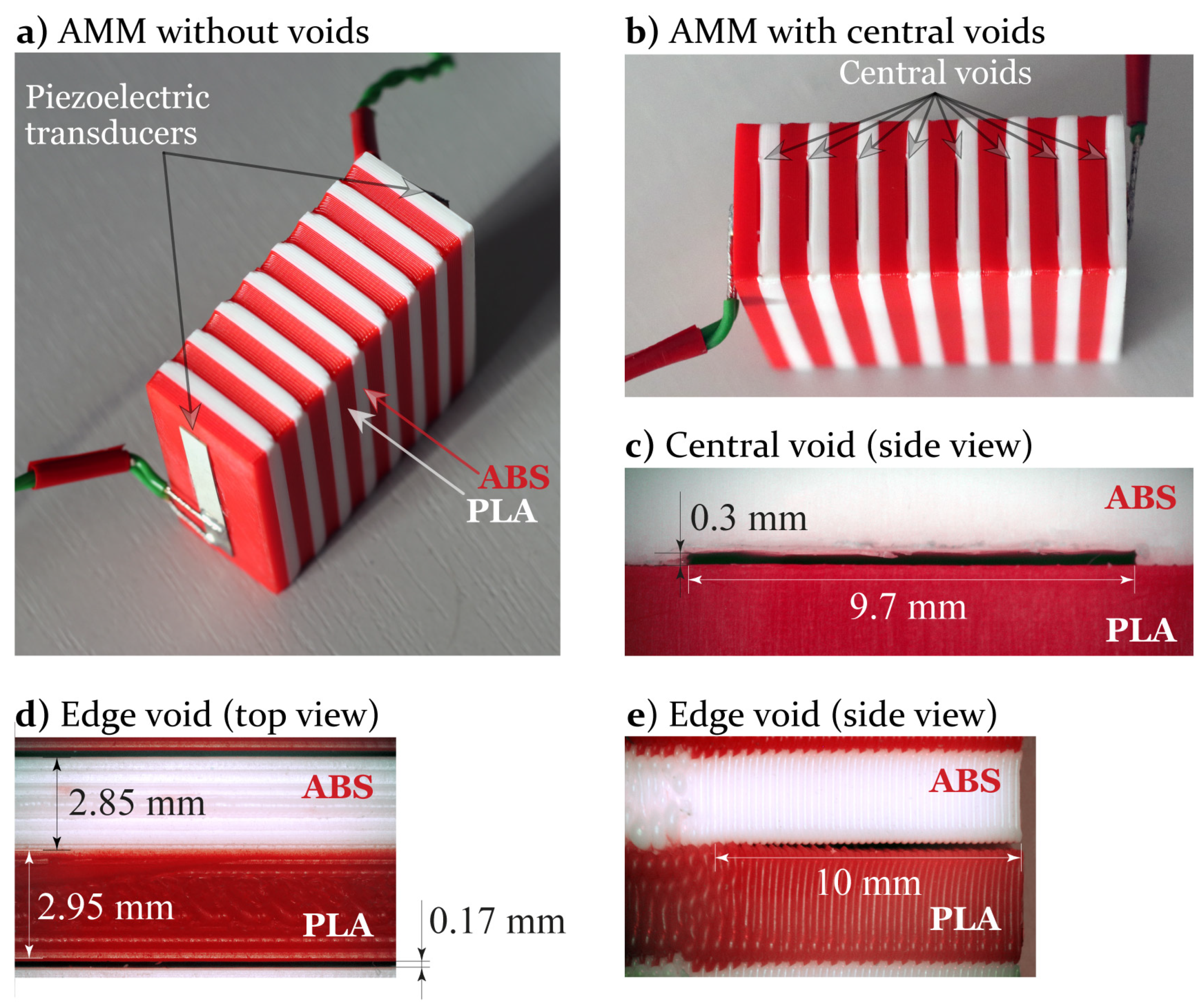
The AMM specimens have been manufactured with a dual-extruder Raise 3D E2 printer, which allows printing with two types of plastics, see Figure 2a,c. Therefore, the dissimilar components do not need to be glued but are fused by a heated extruder during printing. Two kinds of plastics have been used: Nit brand ABS plastic and brand Raise 3d PLA plastic with mass densities 983 kg/m 3 and 1182 kg/m 3 , respectively. The voids have been included in the ABS plastic, which is preferable for the stable and accurate introduction of thin rectangular voids compared to PLA.
Printing was carried out at the surface of the 3D printer table heated up to 110 C, whereas the temperature of the nozzle with the PLA and ABS plastics is heated up to 215 C and 250 C, respectively. The printed layer height is 0.2 mm and the nozzle diameter is 0.4 mm. The manufactured AMM samples have 8 unit cells of 50 mm length and 20 mm width. The AMMs with voids of 50 × 10 × 0.3 mm (Figure 2d) dimension have been manufactured keeping cavities in the sub-layer made of the ABS plastic in the center (Figure 2b,c) of unit-cell or at the edge of AMM (Figure 2d,e). The thicknesses of the sub-layers of the manufactured specimens with central and edge voids are h A = 3.15 mm (PLA), h B = 2.85 mm (ABS) and h A = 3.2 mm (PLA), h B = 2.9 mm, respectively, while the lengths of voids are d = 10 mm and d = 9.7 mm, respectively. After printing, the surfaces of the sample contacting the PWATs were treated with abrasive paper before gluing. To have a reference transmission spectrum, a homogeneous specimen made of ABS plastic only and of the same dimensions has been also manufactured.

2.3. Experimental Setup

GWs in the AMM specimens are generated by a rectangular PWAT made of PIC 155 with dimensions 5 × 40 × 0.2 mm glued with cyanoacrylate at the surface of the structure (Figure 2a). Another PWAT of the same dimensions and material working as a sensor adheres to the opposite surface. The PWAT is driven by a tone-burst transient voltage p ( t ) . Two kinds of input voltage functions are employed. The first is the rectangular pulse of length β μ s
p ( t ) = V 0 1 , 0 t β 0 , otherwise
The second input voltage signal has the form of Hann-windowed N c = 5 cycles of cosine with central frequency f 0 according to
p ( t ) = V 0 1 2 cos ( 2 π f 0 t ) 1 cos 2 π f 0 t N c , 0 < t < N c f 0
The signal is generated by a Tektronix AFG 3021B arbitrary signal generator, where voltage V 0 = 3 V is applied and is then preamplified by a Ciprian HVA-400 external high-frequency power amplifier before being applied to the PWAT so that output voltage V 0 150 V. The measurements have been repeated 1000 times and then the averaged signal is analyzed. The sensor signal is measured by a Picoscope 5442D oscilloscope. To compare with the employed two-dimensional mathematical model, two sides of the AMM specimen parallel to plane x 2 O x 1 have been covered by plasticine, which allows the reduction of extra reflections, which cannot be taken into account by the model.

3. Simulation

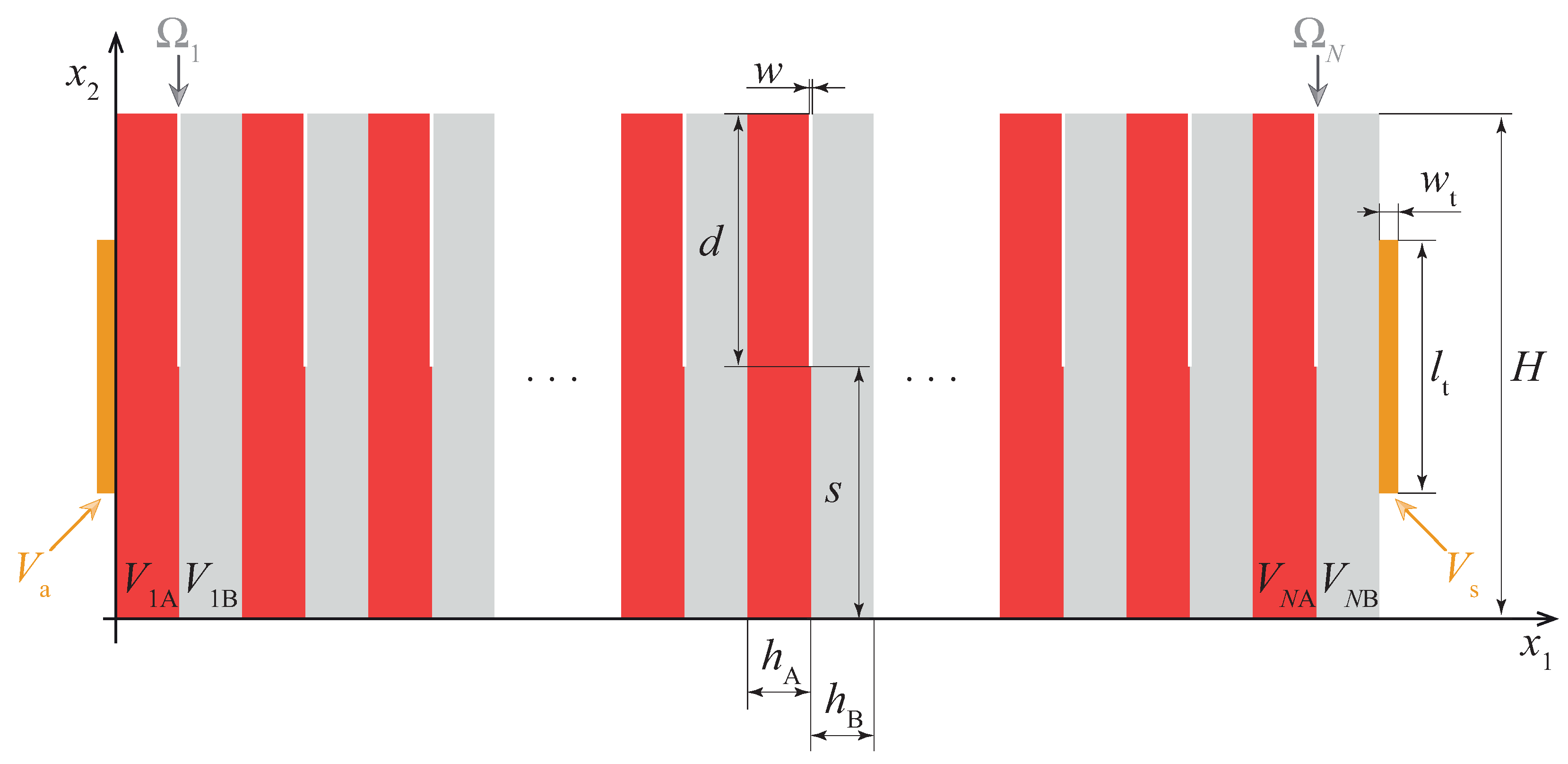
To simulate wave propagation in the considered direction, in-plane wave motion excited in the AMM structure, which is the stack of periodic elastic rectangular layers as shown in Figure 3, is considered. The AMM structure V is composed of N two-layered unit-cells made of materials denoted as A and B (each elastic layer V j n of height H and width h j is described by the elastic constants C i j k l ( j ) and the mass densities ρ ( j ) , j = { A , B } ) with thin planar crack-like interfacial rectangular voids Ω n , n = 1 , N ¯ of width w and length d located at the distance s from the boundary x 2 = 0 . Two PWATs V j , j = { a , s } bonded at the outer boundaries x 2 = 0 and x 2 = N ( h A + h B ) are assumed to be of the same dimensions ( w t × l t ) and the same material. The PWATs V a and V s work as an actuator and a sensor, respectively, and are described by their elastic, piezoelectric, dielectric constants C ^ i j k l , e ^ k i j , ε ^ i k , and mass density ρ ^ .
The governing equations for time-harmonic steady-state in-plane motion with the circular frequency ω are written for the piezoelectric and elastic media in terms of the stress tensor σ i j and displacement vector u = { u 1 , u 2 } as
σ i j ( x ) x j + ρ ω 2 u i = 0 .
For PWATs, the electrostatics governing equation
D i ( x ) x i = 0 .
is applied for the electric displacement vector D .
The constitutive relations connecting the stress tensor σ i j , the derivatives of the mechanical displacement vector u i , the electric displacement vector D i , the electric field vector E i = φ / x i ( φ is the electric potential) are given as follows for a piezoelectric material
σ i j = C i j k l u k , l e k i j E k ,
D i = e i k l u k , l + ε i k E k .
The substitution of the constitutive relations into governing Equations (2) and (3) leads to the governing equations written in terms of the displacement vector u and electric potential φ (for PWATs). For the elastic media, the piezoelectric and dielectric constants, the electric potential, as well as Equation (3), should be omitted.
The continuity boundary conditions
u = τ = 0
are assumed at the internal interfaces in the AMM structure. Here a square bracket denotes the jump of a vector function, while τ = { σ 12 , σ 22 } is the traction vector at the interfaces. The outer boundaries of the structure and faces of the voids Ω n are assumed to be traction-free
σ i j ( x ) n j ( x ) = 0 , x Ω n V
where n is the normal vector of the surface.
The electrodes of the PWATs connected to the AMM structure are assumed to be grounded, i.e.,
φ ( x ) = 0 , x V s V N B V a V 1 A .
A given electric potential ϕ a is applied at the outer electroded surface of the actuator S a = V a { x 2 = w t } , i.e.,
φ = ϕ a , x S a ,
whereas an unknown electric potential at the outer electrode surface of the sensor S s = V s { x 2 = ( h A + h B ) n + w t } is to be determined using the following boundary conditions:
φ ( x ) = ϕ s , x S s ,
Q ( n ) ( u , φ ) = S s D 1 ( x ) d S = 0 ,
where Q ( u , ϕ ) is the electric charge and the constant electric potential ϕ s is assumed to be unknown.
To calculate band diagrams, i.e., dispersion relation k ( f ) between the wavenumber k and the frequency f, let us consider a single unit-cell of thickness h A + h B composed of two sublayers V 1 A and V 1 B . The Floquet boundary conditions are stated at the two outer boundaries of the unit cell:
u ( 0 , x 2 ) = u ( h A + h B , x 2 ) e i k ( h A + h B )
The eigenvalues of the boundary value problem (2), (4), (5), (10) correspond to the roots of the dispersion equation and describe GWs propagating in the waveguide.
The numerical results presented in Section 4 are calculated via the FEM. The details related to the employment of the spectral finite element method as well as the validation and the comparison with the commercial FEM software COMSOL Multiphysics software can be found in [32]. The fourth-order elements and at least ten elements per wavelength have been used for the calculations presented in this study. The material properties used in the simulations performed using the FEM are given in Table 1. For the plastics PLA and ABS, an assumption of isotropic media has been used and the material constants have been taken from the literature [38,39]. Therefore, only Young’s modulus E and Poisson ratio ν are listed in Table 1. The dimensions of the unit-cells of the manufactured AMM specimens as given in Section 2.2 and 16 unit-cells have been used for the simulation.

4. Analysis

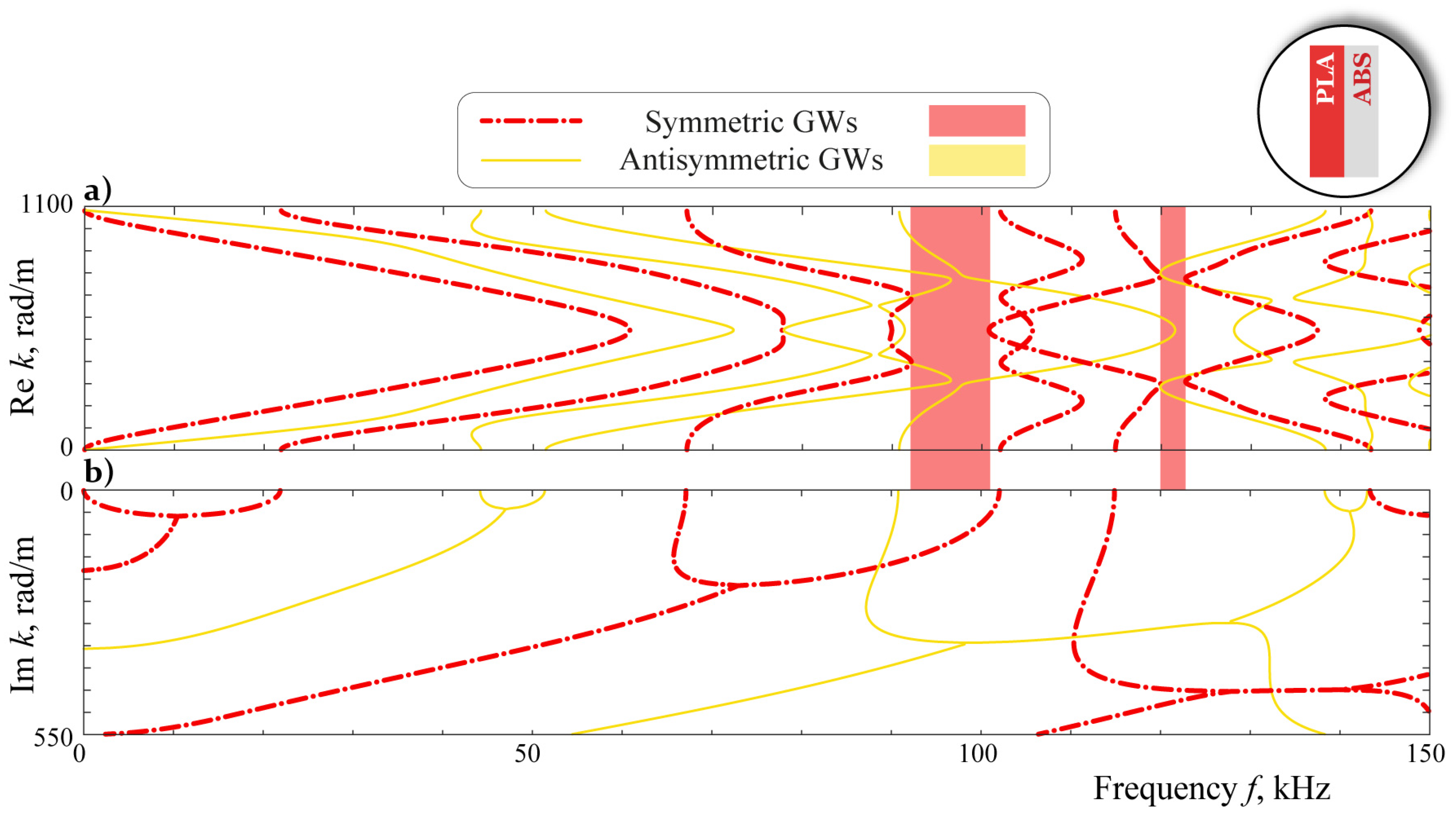
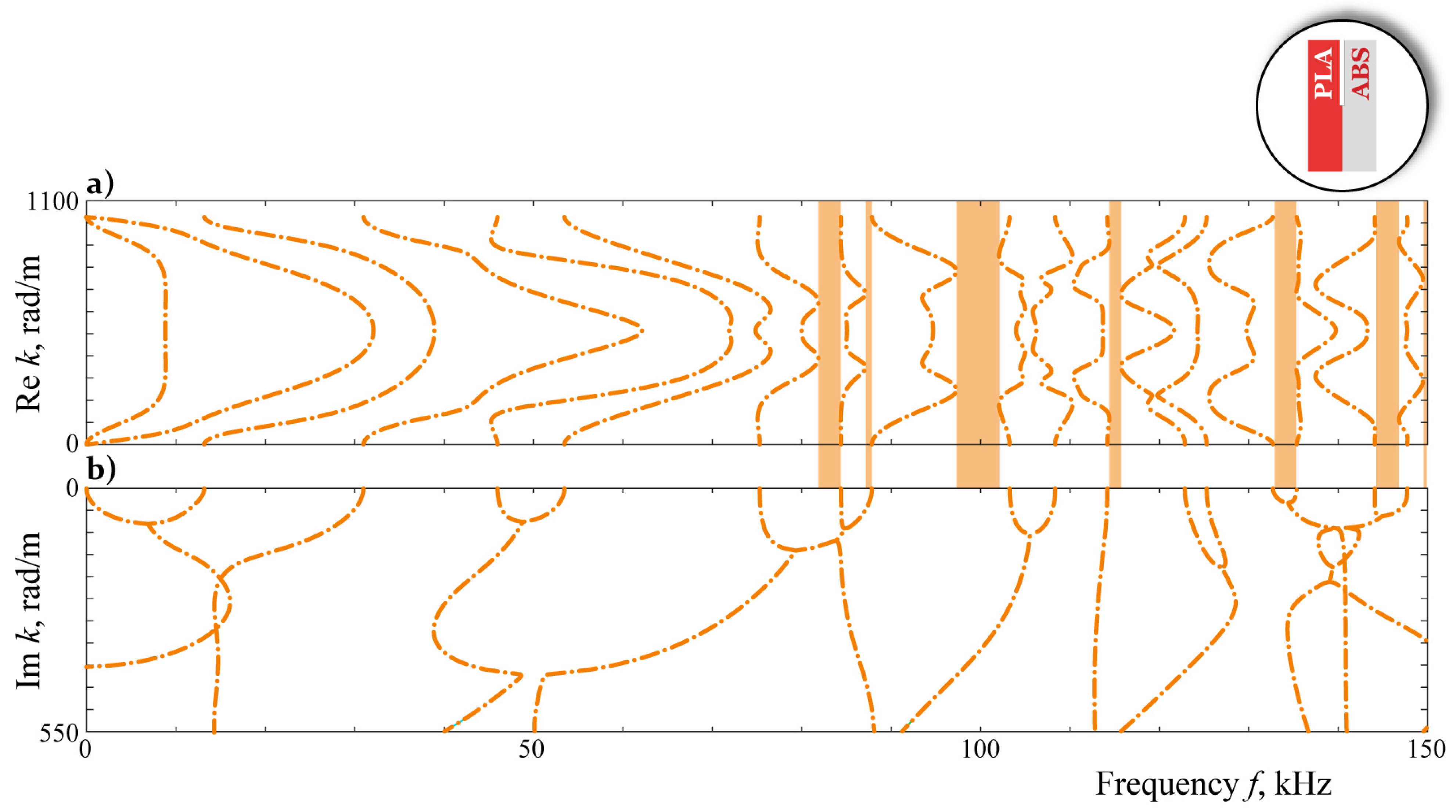
Symmetric (or longitudinal waves) and antisymmetric (or bending waves) GWs can propagate in AMM without voids and with central voids, whereas GWs cannot be classified for the AMM with edge voids considered in this study. The real and imaginary parts of the roots of the dispersion equation related to the boundary value problem (2), (4), (5), (10) calculated via the FEM are depicted in Figure 4, Figure 5 and Figure 6 for the frequencies up to 150 kHz. Band gaps for symmetric GWs (SGWs) and antisymmetric GWs, where GWs decay, are marked by colored rectangles.
One can see that only two band gaps are observed for symmetric GWs in AMMs without voids, whereas antisymmetric GWs propagate without attenuation for all frequencies in the range up to 150 kHz. The introduction of central voids increases the number of band gaps and induces them for antisymmetric GWs, which can be explained by local resonances induced due to the presence of additional scatterers, i.e., voids. For AMMs with edge voids, symmetry is no anymore observed and GWs cannot be classified in the same way as for AMMs without voids and with central voids. The band gaps for AMMs with edge voids are relatively narrow: the widest bands in the second band gap around 100 kHz is about 5 kHz width.
To validate experimentally blocking properties of the considered kind of AMMs with voids, the transmission coefficient is employed. In the experiment, the voltage signal s ( t ) is measured at the sensor for a given input impulse voltage p ( t ) . The spectrum of the signal is calculated as the Fourier transform of the measured signal s ( t ) is used to obtain the transmission coefficient with respect to the circular frequency f
η + ( f ) = 1 S norm 0 T s ( t ) e 2 i π f t d t ,
where S norm = 10 3 has been used to normalize the spectrum of the signal. The theoretically predicted value of the transmission coefficient is directly calculated as the voltage computed for a given frequency f by
γ + ( f ) = ϕ s ( f ) .
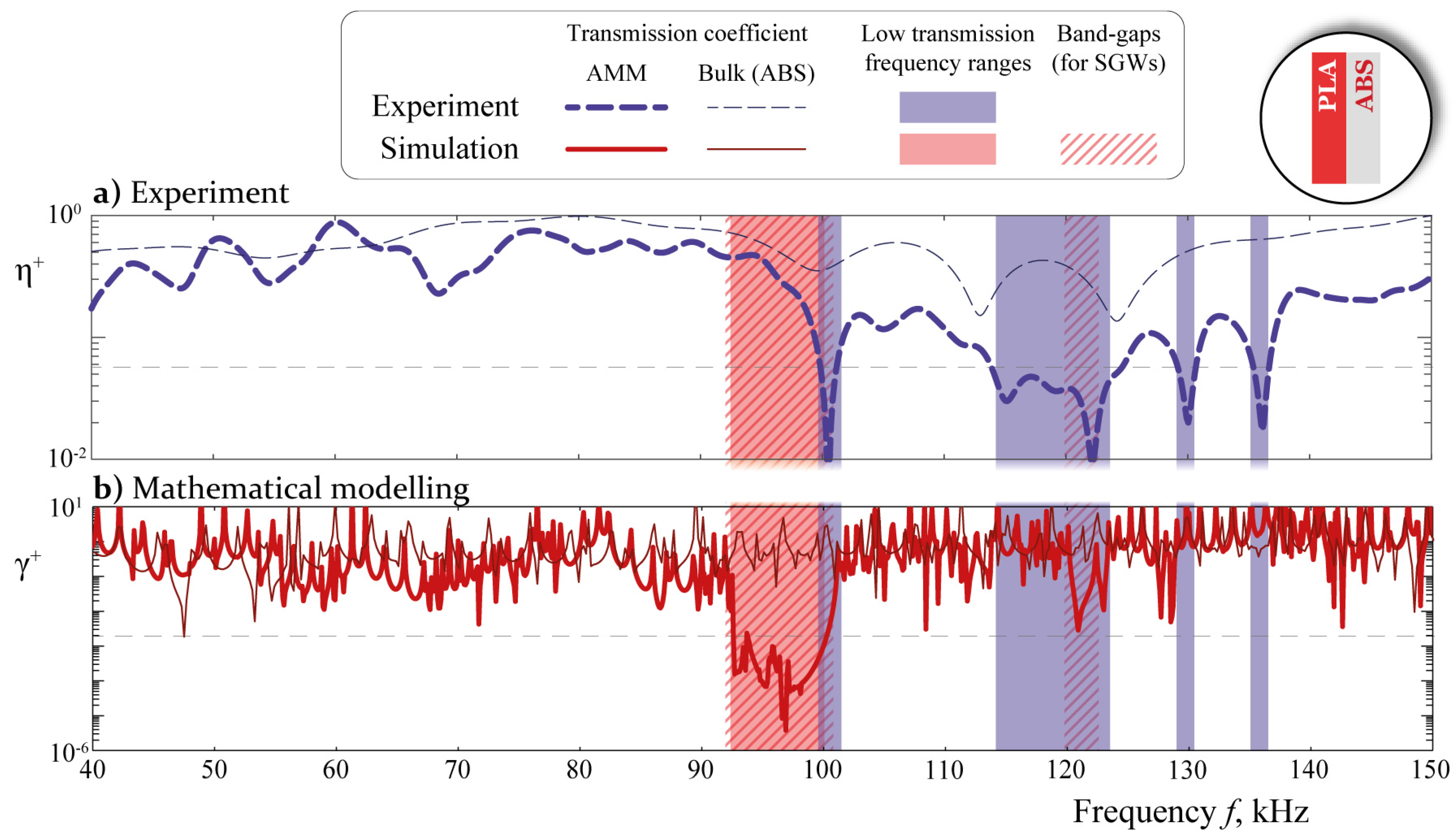
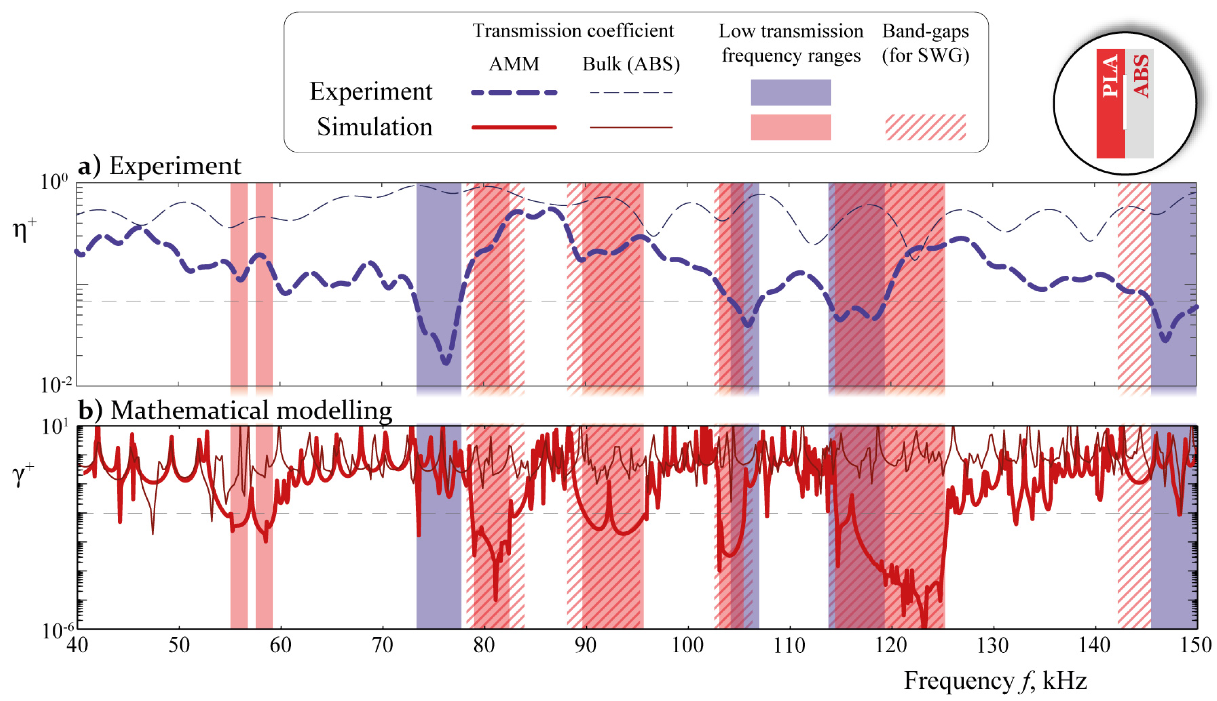
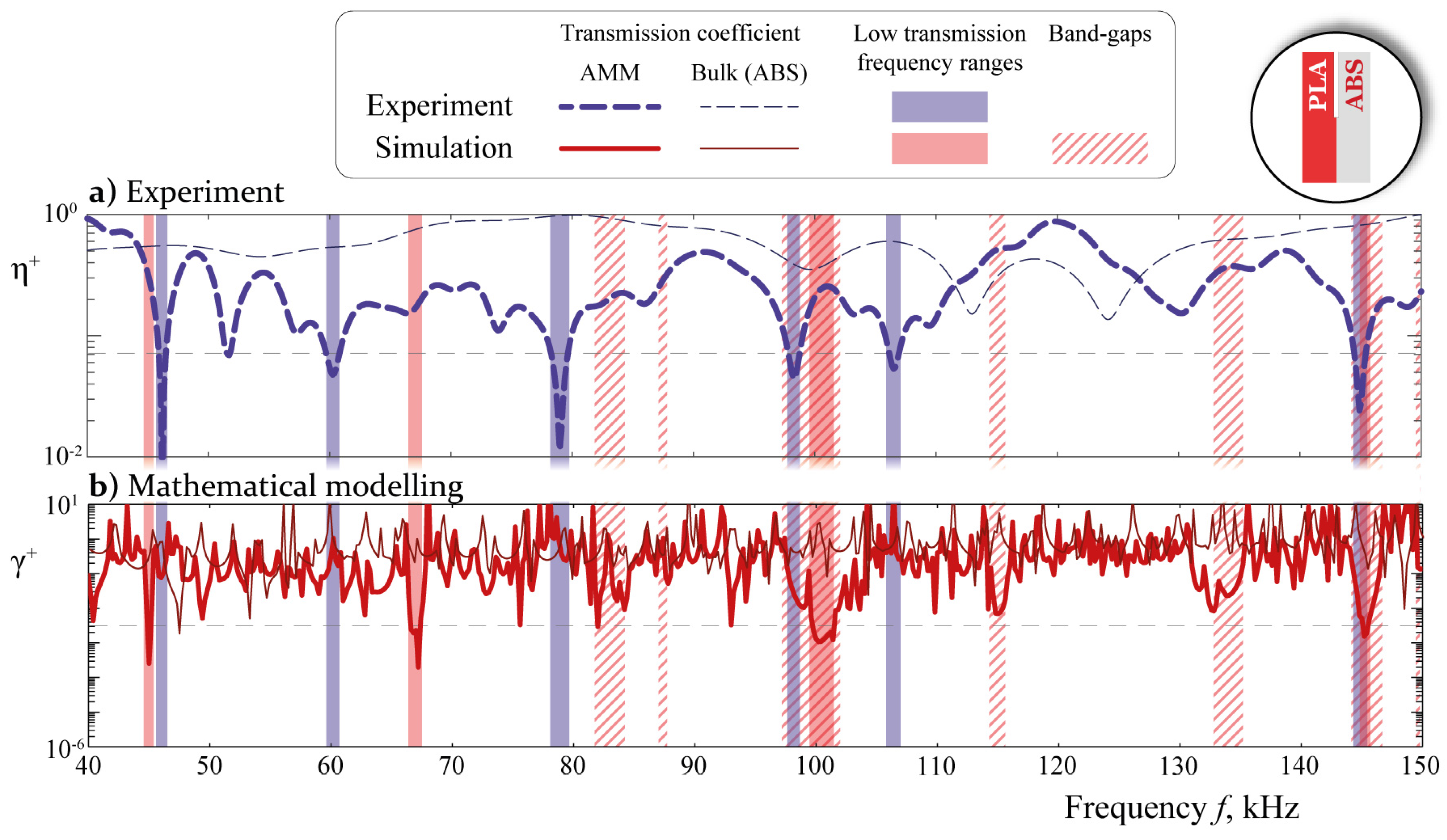
Since the PWATs are glued parallel to the ribs of the specimen, antisymmetric GWs are not generally excited in the AMM specimen. Therefore, symmetric vibrations of AMMs with central voids and without voids are sensed. Figure 7, Figure 8 and Figure 9 demonstrate the transmission coefficients measured via the sensor η + ( f ) (dashed lines) and the theoretically predicted γ + ( f ) (solid lines) for the PLA/ABS AMMs with and without voids. As a reference level, thin lines showing transmission spectra for a bulk waveguide made of ABS plastic are depicted. The homogeneous stripes of the same color exhibit frequency ranges, where low transmission is observed. In these ranges, the transmission coefficients are lower than the threshold chosen to be equal to 0.07 and 0.002, respectively, for the experimental and theoretical values. The thresholds have been chosen to distinguish frequency ranges, where sufficient attenuation of the propagating guided wave is observed. The values have been chosen to have at least 10 and 1000 times amplitude decay in transmission coefficients obtained experimentally and theoretically, respectively. The striped zones show theoretical band gaps, which are also demonstrated in Figure 4, Figure 5 and Figure 6. Examples of signals measured by the sensor are shown in Figure 10a for all four specimens. In this case, Hann-windowed signal with central frequency f 0 = 75 kHz, which lies in the center of the low transmission frequency range for AMM with central voids, has been applied at the piezoelectric actuator. The Fourier transforms of these signals are depicted in Figure 10b, which also reveals that narrow frequency ranges of low transmission are not related to the form of the input signal.
Relatively narrow dips in the experimentally obtained transmission coefficients η + ( f ) are visible for the three specimens, but they are not observed in bulk material (ABS plastic). The dips are not very deep due to the relatively small number of unit cells. The band gaps are also observed in the plots of the transmission coefficients γ + ( f ) computed via the mathematical model. Though these figures do not demonstrate a perfect coincidence between the theoretical and the experimental transmission coefficients, the evident zones of local minima corresponding to bandgaps estimated theoretically and experimentally correlate mostly. Therefore, one can conclude that even a combination of various plastics with relatively similar material properties can provide band gaps.

5. Discussion

This paper reports the first example of the manufacturing of the novel kind AMM with crack-like inhomogeneities or voids, which were recently proposed by the authors in [32]. The wave transmission spectra for the manufactured AMM measured by the piezoelectric sensor exhibit low transmission frequency ranges, where amplitudes are 20–100 times smaller than in the homogeneous bulk specimen made of ABS plastic. Since such decay is obtained for 8-unit cells only, it allows for identifying such frequency ranges as band gaps. Though the experimental and theoretical transmission coefficients do not fit perfectly, a qualitatively reasonable correlation of the observed and predicted band gaps for the considered novel AMMs is obtained.
The revealed discrepancy might be due to the errors in the material properties used in the numerical simulations and manufacturing. For instance, numerical analysis shows that the band gaps are very sensitive to material properties and geometrical parameters. Thus, a 0.02 change in Poisson’s ratio leads to a 2–10 kHz deviation in the location and width of band gaps. As a further study prior to the practical application of the considered kind of AMM, a careful investigation of material properties of the plastics used in the experiment including attenuation should be provided using ultrasonic methods, e.g., the identification procedure based on the laser Doppler vibrometry and proposed in [40,41] can be employed. Moreover, the 3D printing process might lead to slightly anisotropic properties of some sub-layers and fuzzy interfaces, which should be described using anisotropic and functionally graded material properties.
The present report with the proposed design and the manufacturing strategy using additive manufacturing should be useful for further studies related to AMMs with narrow crack-like voids as local resonators. Thus, various combinations of materials forming unit cells, which can be efficiently coupled, should be examined to provide wider band-gaps and to investigate elastic wave conversion [42] or the unidirectional nonreciprocal transmission of energy Wang et al. [33]. The latter has potential applications in vibration isolation, information processing, and the design of acoustic devices based on wave conversion and filtering for the purposes of NDE.

Author Contributions

Conceptualization, M.V.G., Y.W. and C.Z.; methodology, M.V.G., Y.W., C.Z. and I.A.M.; software, Y.W. and M.V.G.; validation, M.V.G., I.A.M. and A.D.K.; formal analysis, M.V.G., A.D.K. and E.A.O.; investigation, I.A.M., A.N.S., and K.K.K.; resources, M.V.G., S.A.M. and I.A.M.; data curation, K.K.K., A.N.S., I.A.M., E.A.O. and M.V.G.; writing—original draft preparation, M.V.G., A.N.S. and C.Z.; writing—review and editing, M.V.G., A.N.S. and C.Z.; visualization, M.V.G. and I.A.M.; project administration, M.V.G., S.A.M. and C.Z. All authors have read and agreed to the published version of the manuscript.

Funding

This research was funded by the Russian Science Foundation (Project 22-11-00261).

Institutional Review Board Statement

Not applicable.

Data Availability Statement

Not applicable.

Acknowledgments

The authors are grateful to A.A. Eremin and I.A. Bareiko for valuable discussions related to experimental works.

Conflicts of Interest

The authors declare no conflict of interest.

References

  1. Vasiliev, V.V.; Morozov, E.V. Advanced Mechanics of Composite Materials and Structures, 4th ed.; Elsevier: Amsterdam, The Netherlands, 2018; p. 882. [Google Scholar]
  2. Rubino, F.; Nisticò, A.; Tucci, F.; Carlone, P. Marine application of fiber reinforced composites: A review. J. Mar. Sci. Eng. 2020, 8, 26. [Google Scholar] [CrossRef] [Green Version]
  3. Wu, W.; Xia, R.; Qian, G.; Liu, Z.; Razavi, J.; Berto, F.; Gao, H. Mechanostructures: Rational mechanical design, fabrication, performance evaluation, and industrial application of advanced structures. Prog. Mater. Sci. 2023, 131, 101021. [Google Scholar] [CrossRef]
  4. Lu, M.H.; Feng, L.; Chen, Y.F. Phononic crystals and acoustic metamaterials. Mater. Today 2009, 12, 34–42. [Google Scholar] [CrossRef]
  5. Deymier, P. Acoustic Metamaterials and Phononic Crystals; Springer: Berlin/Heidelberg, Germany, 2013; p. 378. [Google Scholar]
  6. Ma, F.; Wang, C.; Liu, C.; Wu, J.H. Structural designs, principles, and applications of thin-walled membrane and plate-type acoustic/elastic metamaterials. J. Appl. Phys. 2021, 129, 231103. [Google Scholar] [CrossRef]
  7. Dogra, S.; Gupta, A. Design, manufacturing, and acoustical analysis of a Helmholtz resonator-based metamaterial plate. Acoustics 2021, 3, 630–641. [Google Scholar] [CrossRef]
  8. Kadic, M.; Milton, G.W.; van Hecke, M.; Wegener, M. 3D metamaterials. Nat. Rev. Phys. 2019, 1, 198–210. [Google Scholar] [CrossRef]
  9. Liao, G.; Luan, C.; Wang, Z.; Liu, J.; Yao, X.; Fu, J. Acoustic metamaterials: A review of theories, structures, fabrication approaches, and applications. Adv. Mater. Technol. 2021, 6, 2000787. [Google Scholar] [CrossRef]
  10. Du, Y.; Wu, W.; Chen, W.; Lin, Y.; Chi, Q. Control the structure to optimize the performance of sound absorption of acoustic metamaterial: A review. AIP Adv. 2021, 11, 060701. [Google Scholar] [CrossRef]
  11. Alam, Z.; Sharma, A.K. Functionally Graded Soft Dielectric Elastomer Phononic Crystals: Finite Deformation, Electro-Elastic Longitudinal Waves, and Band Gaps Tunability via Electro-Mechanical Loading. Int. J. Appl. Mech. 2022, 14, 2250050. [Google Scholar] [CrossRef]
  12. Dai, H.; Zhang, X.; Zheng, Y.; Pei, W.; Zhou, R.; Liu, R.; Gong, Y. Review and prospects of metamaterials used to control elastic waves and vibrations. Front. Phys. 2022, 10, 1179. [Google Scholar] [CrossRef]
  13. Yang, Z.; Mei, J.; Yang, M.; Chan, N.H.; Sheng, P. Membrane-type acoustic metamaterial with negative dynamic mass. Phys. Rev. Lett. 2008, 101, 204301. [Google Scholar] [CrossRef] [PubMed]
  14. Zhu, R.; Liu, X.; Hu, G.; Yuan, F.; Huang, G. Microstructural designs of plate-type elastic metamaterial and their potential applications: A review. Int. J. Smart Nano Mater. 2015, 6, 14–40. [Google Scholar] [CrossRef] [Green Version]
  15. Lee, M.K.; Kim, Y.Y. Add-on unidirectional elastic metamaterial plate cloak. Sci. Rep. 2016, 6, 20731. [Google Scholar] [CrossRef] [PubMed] [Green Version]
  16. Wang, W.; Bonello, B.; Djafari-Rouhani, B.; Pennec, Y.; Zhao, J. Double-negative pillared elastic metamaterial. Phys. Rev. Appl. 2018, 10, 064011. [Google Scholar] [CrossRef]
  17. Kanev, N. Resonant metasurfaces with a tangential impedance. Acoustics 2022, 4, 903–914. [Google Scholar] [CrossRef]
  18. Talonov, A.; Savatorova, V.; Vlasov, A. High-frequency approximation of plane wave propagation in an elastic medium with periodic distribution of cracks. Compos. Mech. Comput. Appl. 2017, 8, 339–354. [Google Scholar] [CrossRef]
  19. Chen, Z.; Wang, G.; Shi, F.; Lim, C. Analytical modeling and numerical analysis for tunable topological phase transition of flexural waves in active sandwiched phononic beam systems. Int. J. Mech. Sci. 2022, 223, 107292. [Google Scholar] [CrossRef]
  20. Achenbach, J.D.; Li, Z.L. Propagation of horizontally polarized transverse waves in a solid with a periodic distribution of cracks. Wave Motion 1986, 8, 371–379. [Google Scholar] [CrossRef]
  21. Su, X.; Norris, A.N. Focusing, refraction, and asymmetric transmission of elastic waves in solid metamaterials with aligned parallel gaps. J. Acoust. Soc. Am. 2016, 139, 3386–3394. [Google Scholar] [CrossRef] [Green Version]
  22. Su, X.; Lu, Z.; Norris, A.N. Elastic metasurfaces for splitting SV- and P-waves in elastic solids. J. Appl. Phys. 2018, 123, 091701. [Google Scholar] [CrossRef]
  23. Zhbadinskii, I.Y. Interaction of one-periodic disk-shaped cracks under an incident elastic harmonic wave. Mech. Solids 2016, 51, 127–134. [Google Scholar] [CrossRef]
  24. Mykhas’kiv, V.V.; Zhbadynskyi, I.Y.; Zhang, C. On propagation of time-harmonic elastic waves through a double-periodic array of penny-shaped cracks. Eur. J. Mech. A Solids 2019, 73, 306–317. [Google Scholar] [CrossRef]
  25. Remizov, M.Y.; Sumbatyan, M.A. Three-dimensional one-mode penetration of elastic waves through a doubly periodic array of cracks. Math. Mech. Solids 2018, 23, 636–650. [Google Scholar] [CrossRef]
  26. Sumbatyan, M.; Remizov, M. On 3D theory of acoustic metamaterials with a triple-periodic system of interior obstacles. Contin. Mech. Thermodyn. 2019, 31, 1743–1756. [Google Scholar] [CrossRef]
  27. Golub, M.V.; Doroshenko, O.V. Boundary integral equation method for simulation scattering of elastic waves obliquely incident to a doubly periodic array of interface delaminations. J. Comput. Phys. 2019, 376, 675–693. [Google Scholar] [CrossRef]
  28. Yan, Z.Z.; Zhang, C.; Wang, Y.S. Analysis of wave propagation and localization in periodic/disordered layered composite structures by a mass-spring model. Appl. Phys. Lett. 2009, 161909, 224303. [Google Scholar] [CrossRef]
  29. Golub, M.V.; Zhang, C. In-plane time-harmonic elastic wave motion and resonance phenomena in a layered phononic crystal with periodic cracks. J. Acoust. Soc. Am. 2015, 137, 238–252. [Google Scholar] [CrossRef] [PubMed]
  30. Golub, M.V.; Doroshenko, O.V.; Fomenko, S.I.; Wang, Y.; Zhang, C. Elastic wave propagation, scattering and localization in layered phononic crystals with arrays of strip-like cracks. Int. J. Solids Struct. 2021, 212, 1–22. [Google Scholar] [CrossRef]
  31. Huang, K.X.; Shui, G.S.; Wang, Y.Z.; Wang, Y.S. Meta-arrest of a fast propagating crack in elastic wave metamaterials with local resonators. Mech. Mater. 2020, 148, 103497. [Google Scholar] [CrossRef]
  32. Wang, Y.; Perras, E.; Golub, M.V.; Fomenko, S.I.; Zhang, C.; Chen, W. Manipulation of the guided wave propagation in multilayered phononic plates by introducing interface delaminations. Eur. J. Mech. A Solids 2021, 88, 104266. [Google Scholar] [CrossRef]
  33. Wang, Y.; Li, A.; Golub, M.V.; Huang, G.; Chen, W.; Zhang, C. Interfacial delamination induced unidirectional propagation of guided waves in multilayered media. Math. Mech. Solids 2022, 27, 1531–1545. [Google Scholar] [CrossRef]
  34. Zubov, Y.; Djafari-Rouhani, B.; Jin, Y.; Sofield, M.; Walker, E.; Neogi, A.; Krokhin, A. Long-range nonspreading propagation of sound beam through periodic layered structure. Commun. Phys. 2020, 3, 155. [Google Scholar] [CrossRef]
  35. Hedayatrasa, S.; Kersemans, M. 3D intra-cellular wave dynamics in a phononic plate with ultra-wide bandgap: Attenuation, resonance and mode conversion. Smart Mater. Struct. 2022, 31, 035010. [Google Scholar] [CrossRef]
  36. Tancogne-Dejean, T.; Diamantopoulou, M.; Gorji, M.B.; Bonatti, C.; Mohr, D. 3D plate-lattices: An emerging class of low-density metamaterial exhibiting optimal isotropic stiffness. Adv. Mater. 2018, 30. [Google Scholar] [CrossRef] [PubMed]
  37. Askari, M.; Hutchins, D.A.; Thomas, P.J.; Astolfi, L.; Watson, R.L.; Abdi, M.; Ricci, M.; Laureti, S.; Nie, L.; Freear, S.; et al. Additive manufacturing of metamaterials: A review. Addit. Manuf. 2020, 36. [Google Scholar] [CrossRef]
  38. Dhaliwal, G.S.; Dundar, M.A. Four point flexural response of acrylonitrile—Butadiene—Styrene. J. Compos. Sci. 2020, 4, 63. [Google Scholar] [CrossRef]
  39. Mirkhalaf, S.M.; Fagerström, M. The mechanical behavior of polylactic acid (PLA) films: Fabrication, experiments and modelling. Mech. Time-Depend. Mater. 2021, 25, 119–131. [Google Scholar] [CrossRef] [Green Version]
  40. Golub, M.V.; Doroshenko, O.V.; Arsenov, M.; Bareiko, I.; Eremin, A.A. Identification of material properties of elastic plate using guided waves based on the matrix pencil method and laser Doppler vibrometry. Symmetry 2022, 14, 1077. [Google Scholar] [CrossRef]
  41. Golub, M.V.; Doroshenko, O.V.; Arsenov, M.A.; Eremin, A.A.; Gu, Y.; Bareiko, I. Improved unsupervised learning method for material properties identification based on mode separation of ultrasonic guided wave. Computation 2022, 10, 93. [Google Scholar] [CrossRef]
  42. Guo, Y.; Liu, F.; Du, Q.; Peng, P. Total conversion between the longitudinal and transverse waves by an ultrathin elastic metamaterial plate with U-shaped slits. Appl. Phys. Express 2022, 15, 127002. [Google Scholar] [CrossRef]
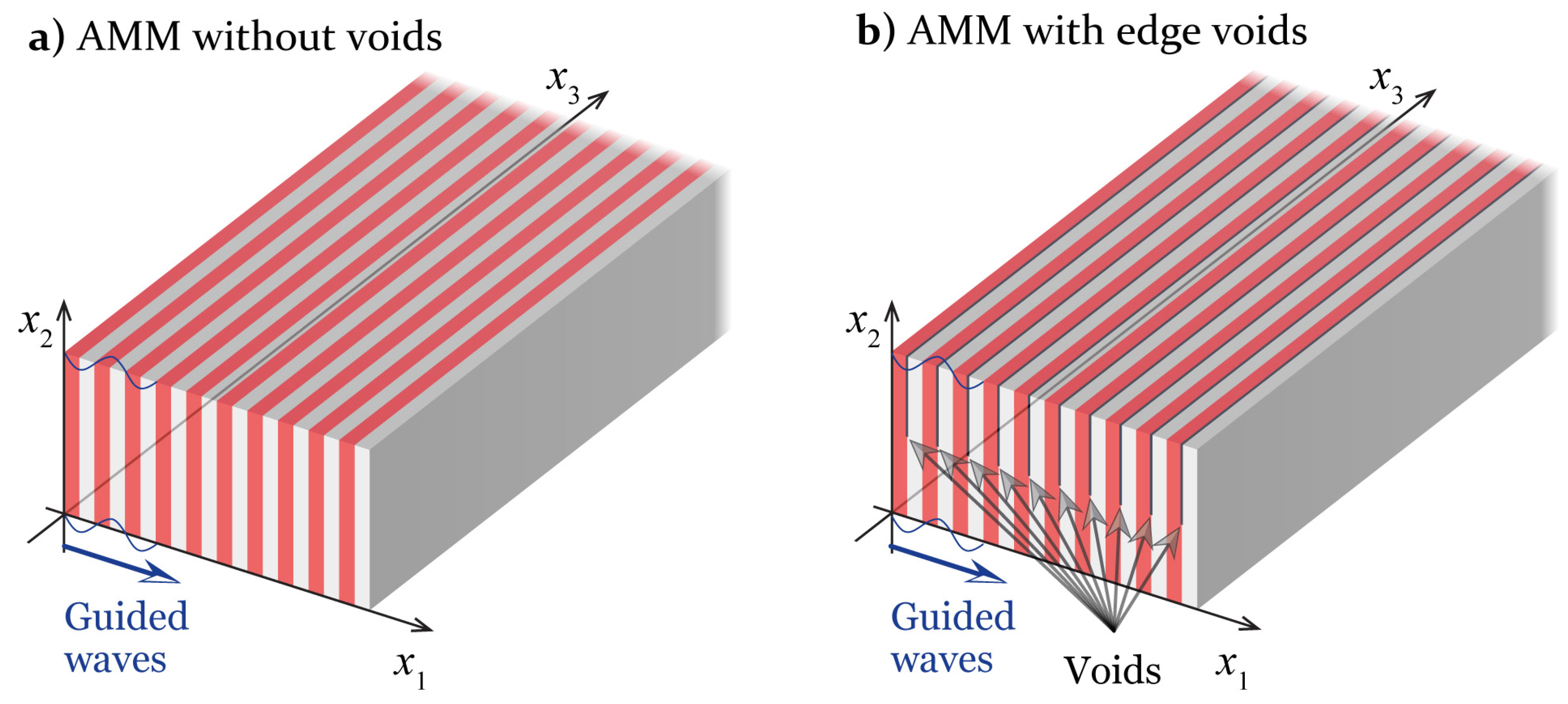
Figure 1. Design of the specimens without voids (a) and with edge voids (b).
Acoustics 05 00008 g001
Figure 2. Photographs of AMM specimens without voids (a), with central voids (b,c) and with edge voids (d,e).
Acoustics 05 00008 g002
Figure 3. Geometry of the problem.
Acoustics 05 00008 g003
Figure 4. The real (a) and imaginary parts (b) of the wavenumbers of propagating symmetric and antisymmetric GWs propagating in AMM without voids.
Acoustics 05 00008 g004
Figure 5. The real (a) and imaginary (b) parts of the wavenumbers of propagating symmetric and antisymmetric GWs propagating in AMM with central voids.
Acoustics 05 00008 g005
Figure 6. The real (a) and imaginary (b) parts of the wavenumbers of propagating GWs propagating in AMM with edge voids.
Acoustics 05 00008 g006
Figure 7. Experimental (a) and theoretical (b) and transmission coefficients η + ( f ) and γ + ( f ) , and the corresponding band-gaps for AMMs without voids.
Acoustics 05 00008 g007
Figure 8. Experimental (a) and theoretical (b) and transmission coefficients η + ( f ) and γ + ( f ) , and the corresponding band-gaps for AMMs with central voids.
Acoustics 05 00008 g008
Figure 9. Experimental (a) and theoretical (b) and transmission coefficients η + ( f ) and γ + ( f ) , and the corresponding band-gaps for AMMs with edge voids.
Acoustics 05 00008 g009
Figure 10. The measured signals s ( t ) and its transmission spectra η + ( f ) for four specimens in the case of Hann-windowed input with f 0 = 75 kHz: bulk ABS, layered AMM without voids, layered AMM with central voids, layered AMM with edge voids.
Acoustics 05 00008 g010
Table 1. Material properties used in the numerics.
MaterialElastic ConstantsPiezoelectric Constants [ C / m 2 ]Dielectric Constants 10 9 [ F / m ]Density [ kg / m 3 ]
PLA E = 4.4  GPa1183
ν = 0.3
ABS E = 1.5  GPa983
ν = 0.4
PIC 155 C 1111 = 120  GPa e 211 = 7.24 ε 11 = 9.12 7800
C 1112 = 67.3  GPa e 212 = 13.77 ε 22 = 7.55
C 2222 = 94.4  GPa e 112 = 11.91
C 1212 = 22.3  GPa
Disclaimer/Publisher’s Note: The statements, opinions and data contained in all publications are solely those of the individual author(s) and contributor(s) and not of MDPI and/or the editor(s). MDPI and/or the editor(s) disclaim responsibility for any injury to people or property resulting from any ideas, methods, instructions or products referred to in the content.