
Performance Evaluation of Three-Ply Multi-Oriented Laminate Composite Fabricated via Vacuum Assisted Resin Transfer Molding Method under Tensile Loading †

 , ,
, ,
Abstract
:1. Introduction
2. Materials and Methods
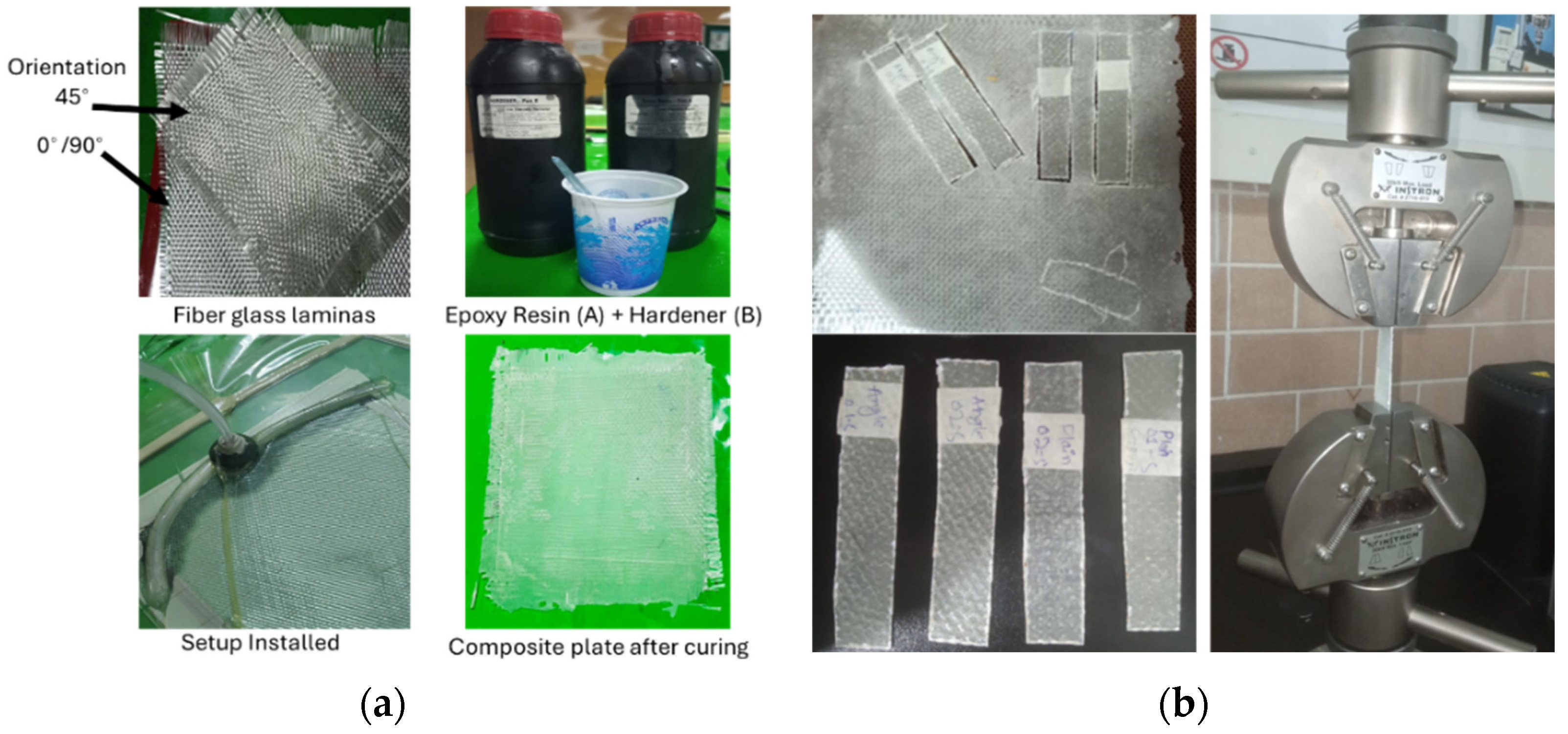
2.1. Materials
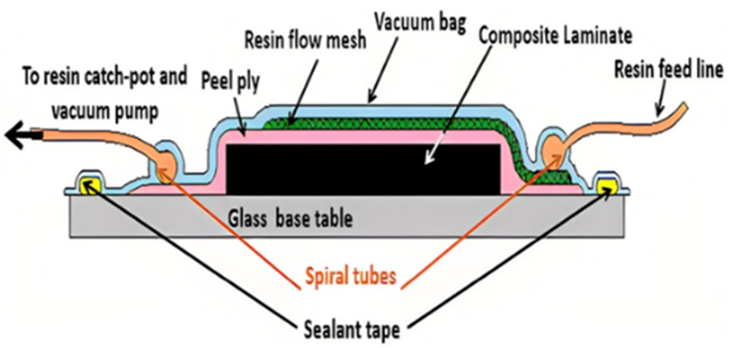
2.2. Methods
2.3. Standard
3. Results and Discussion
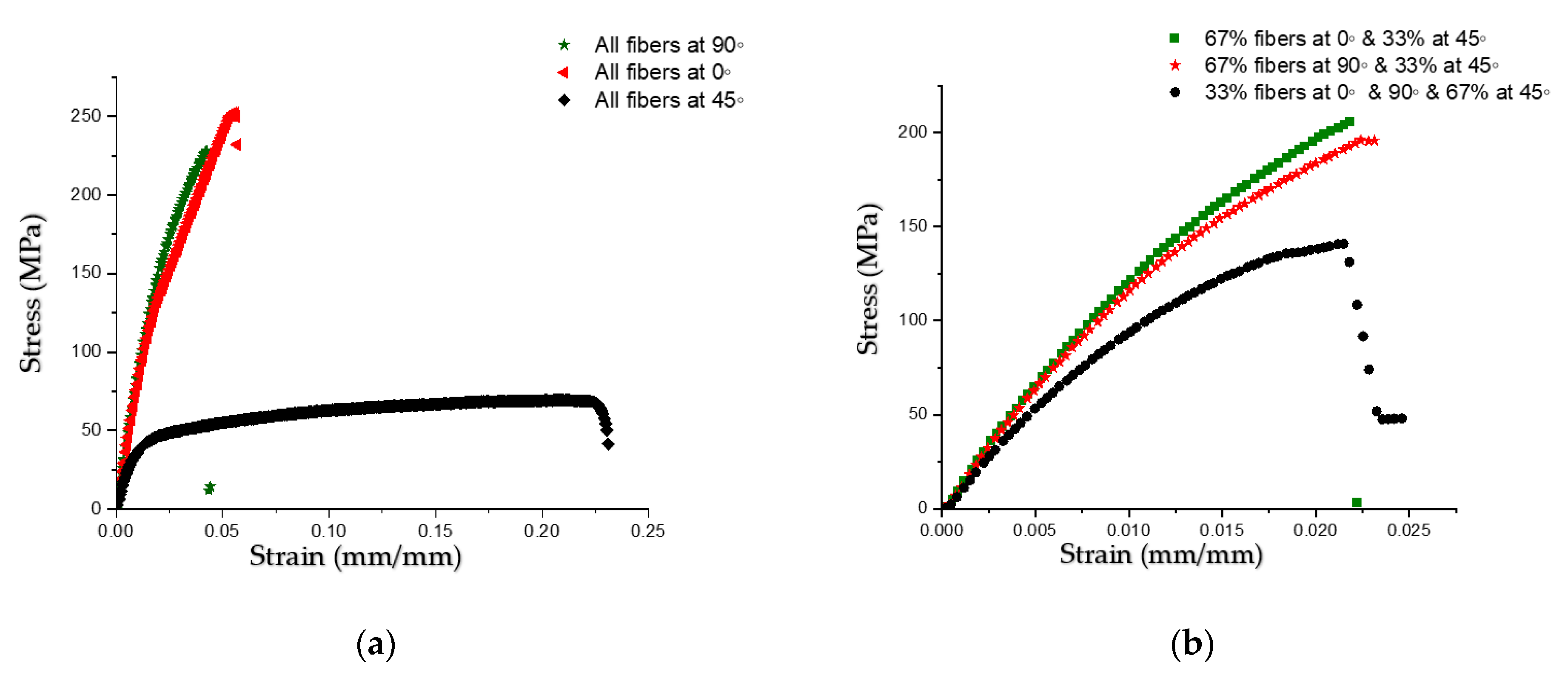
3.1. Results
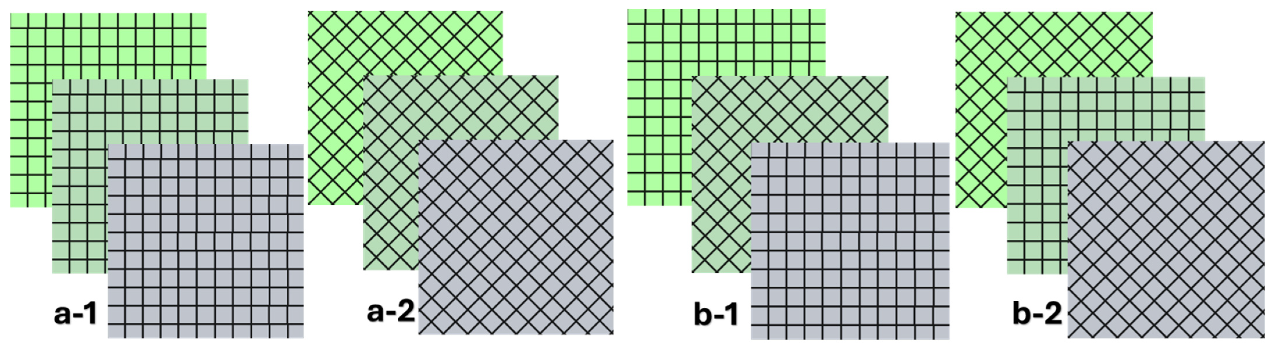
3.1.1. Uniformed Fiber Orientation (Laminate 1)
3.1.2. Sequentially Varying Fiber Orientation (Laminate 2)
3.2. Discussion
3.3. Uncertainity Analysis
4. Conclusions
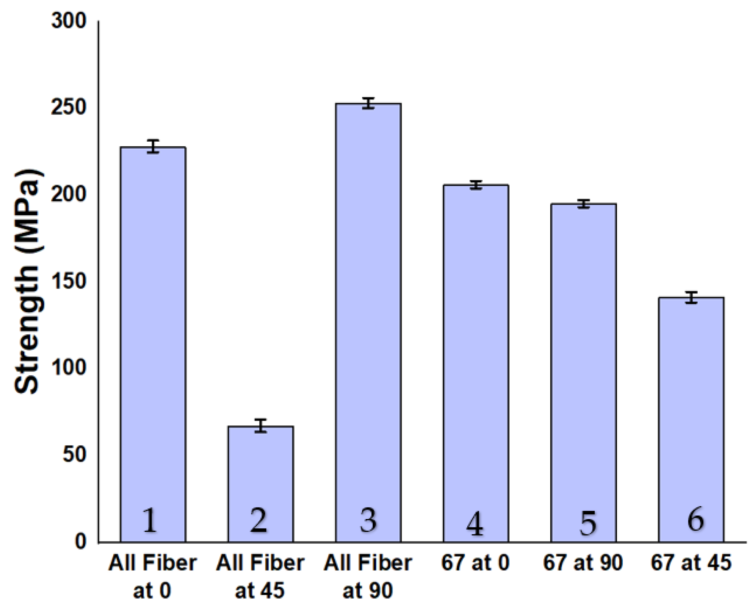
- The highest strength of 253 MPa with minimum deformation having strain of 0.055 achieved in the sample with the maximum number of fibers aligned along the loading direction.
- The lowest strength of 69 MPa with maximum strain of 0.22 was observed in the sample with most fibers oriented at 45° to the loading direction.
- The sample with at least one fiber lamina at 45° to the loading direction shows 18.5% lower strength compared to those with all fibers aligned along the loading direction. Meanwhile, samples with two fiber laminates at 45° exhibit even lower strength but have 2.8 times better strain showing ductile behaviors.
Author Contributions
Funding
Institutional Review Board Statement
Informed Consent Statement
Data Availability Statement
Acknowledgments
Conflicts of Interest
References
- Alam, M.A.; Ya, H.H.; Sapuan, S.M.; Mamat, O.; Parveez, B.; Yusuf, M.; Masood, F.; Ilyas, R.A. Recent Advancements in Advanced Composites for Aerospace Applications: A Review. In Advanced Composites in Aerospace Engineering Applications; Mazlan, N., Sapuan, S.M., Ilyas, R.A., Eds.; Springer International Publishing: Cham, Switzerland, 2022; pp. 319–339. [Google Scholar] [CrossRef]
- Rasheed, A.; Hussain, M.; Ullah, S.; Ahmad, Z.; Kakakhail, H.; Riaz, A.A.; Khan, I.; Ahmad, S.; Akram, W.; Eldin, S.M. Experimental investigation and Taguchi optimization of FDM process parameters for the enhancement of tensile properties of Bi-layered printed PLA-ABS. Mater. Res. Express 2023, 10, 095307. [Google Scholar] [CrossRef]
- Freeman, W. The use of composites in aircraft primary structure. Compos. Eng. 1993, 3, 767–775. [Google Scholar] [CrossRef]
- Li, D. Layerwise theories of laminated composite structures and their applications: A review. Arch. Comput. Methods Eng. 2021, 28, 577–600. [Google Scholar] [CrossRef]
- Rajak, D.K.; Wagh, P.H.; Linul, E. Manufacturing technologies of carbon/glass fiber-reinforced polymer composites and their properties: A review. Polymers 2021, 13, 3721. [Google Scholar] [CrossRef] [PubMed]
- Ashfaq, B.; Hussain, G.; Khan, M.; Ilyas, M. Mechanical characterization of innovative 3D-printed auxetic (NPR) structures: Role of considering anisotropy on accuracy of numerical modeling. Int. J. Adv. Manuf. Technol. 2024, 130, 4845–4859. [Google Scholar] [CrossRef]
- Ashfaq, B.; Hussain, G.; Khan, M.B.; Alkahtani, M.; Wei, H. A novel design of mono and bi-cells based hybrid auxetic structures and assessment of their compressive properties. J. Mater. Res. Technol. 2024, 28, 1620–1632. [Google Scholar] [CrossRef]
- Kim, S.-Y.; Shim, C.S.; Sturtevant, C.; Song, H.C. Mechanical properties and production quality of hand-layup and vacuum infusion processed hybrid composite materials for GFRP marine structures. Int. J. Nav. Archit. Ocean. Eng. 2014, 6, 723–736. [Google Scholar] [CrossRef]
- Ramesh, M.; Palanikumar, K.; Reddy, K.H. Influence of fiber orientation and fiber content on properties of sisal-jute-glass fiber-reinforced polyester composites. J. Appl. Polym. Sci. 2016, 133, 42968. [Google Scholar] [CrossRef]
- Margabandu, S.; Subramaniam, S. Experimental evaluation and numerical validation of bending and impact behaviours of hybrid composites with various stacking arrangements. Mater. Res. Express 2019, 6, 125305. [Google Scholar] [CrossRef]
- Prabhu, L.; Krishnaraj, V.; Sathish, S.; Gokulkumar, S.; Sanjay, M.R.; Siengchin, S. Mechanical and Acoustic Properties of Alkali-Treated Sansevieria ehrenbergii/Camellia sinensis Fiber–Reinforced Hybrid Epoxy Composites: Incorporation of Glass Fiber Hybridization. Appl. Compos. Mater. 2020, 27, 915–933. [Google Scholar] [CrossRef]
- Ramesh, M.; Sudharsan, P. Experimental Investigation of Mechanical and Morphological Properties of Flax-Glass Fiber Reinforced Hybrid Composite using Finite Element Analysis. Silicon 2018, 10, 747–757. [Google Scholar] [CrossRef]
- Banakar, P.; Shivananda, H.; Niranjan, H.B. Influence of Fiber Orientation and Thickness on Tensile Properties of Laminated Polymer Composites. Int. J. Pure Appl. Sci. Technol. 2012, 9, 61. [Google Scholar]
- All Noman, A.; Mohammad Shohel, S.; Hossain Riyad, S.; Sen Gupta, S. Investigate the mechanical strength of laminated composite carbon fiber with different fiber orientations by numerically using finite element analysis. Mater. Today Proc. 2023, in press. [Google Scholar] [CrossRef]
- Rajak, D.K.; Pagar, D.D.; Menezes, P.L.; Linul, E. Fiber-Reinforced Polymer Composites: Manufacturing, Properties, and Applications. Polymers 2019, 11, 1667. [Google Scholar] [CrossRef] [PubMed]
- Tamakuwala, V.R. Manufacturing of fiber reinforced polymer by using VARTM process: A review. Mater. Today Proc. 2021, 44, 987–993. [Google Scholar] [CrossRef]
- Mohamed, Y.S.; Abdelbary, A. Theoretical and experimental study on the influence of fiber orientation on the tensile properties of unidirectional carbon fiber/epoxy composite. Alex. Eng. J. 2023, 67, 693–705. [Google Scholar] [CrossRef]
- Elkington, M.; Bloom, L.D.; Ward, C.; Chatzimichali, A.; Potter, K. Hand layup: Understanding the manual process. Adv. Manuf. Polym. Compos. Sci. 2015, 1, 138–151. [Google Scholar] [CrossRef]
- Abdelal, N. Electromagnetic Interference Shielding of Stitched Carbon Fiber Composites. J. Ind. Text. 2020, 49, 773–790. [Google Scholar] [CrossRef]
- Sritharan, R.; Askari, D. A design of experiment study to investigate the effects of hardener concentration, stirring time, and air bubbles on the tensile strength of epoxy resin. J. Elastomers Plast. 2022, 54, 1129–1147. [Google Scholar] [CrossRef]
- Khan, U.; Khan, N.; Khan, A.A.; Ahmad, I.; Zafar, Z. Optimizing the Corrosion Protection Performance of Epoxy Coatings for Cu Substrates: An Electrochemical Perspective. Int. J. Emerg. Eng. Technol. 2024, 3, 9–16. [Google Scholar]
- Pinnell, M.; Fields, R.; Zabora, R. Results of an interlaboratory study of the ASTM standard test method for tensile properties of polymer matrix composites D 3039. J. Test. Eval. 2005, 33, 27–31. [Google Scholar] [CrossRef]
- Zakaria, M.R.; Sabri, F.N.A.M.; Akil, H.M. Chapter 3—Advanced hybrid fiber-reinforced composites for high material performance. In Composite Materials; Low, I.-M., Dong, Y., Eds.; Elsevier: Amsterdam, The Netherlands, 2021; pp. 53–64. [Google Scholar] [CrossRef]

| S/No | Item | Weight in (gm) |
|---|---|---|
| 1 | Glass fiber sheet | 74 |
| 2 | Mesh | 5 |
| 3 | Peel ply | 8 |
| 4 | Plastic covering sheet | 2 |
| 5 | Resin’s inlet/outlet | 37 |
| 6 | Spiral pipe | 14 |
| Total | 140 |
| S: No | Sample Type | Strength (MPa) (Mean) | S. D | Uncertainty |
|---|---|---|---|---|
| 1 | All fibers at 0° | 253 | 5.96 | 3.44 |
| 2 | All fibers at 45° | 69 | 6.25 | 3.61 |
| 3 | All fibers at 90° | 228 | 4.95 | 2.86 |
| 4 | 67% fibers at 0° and 33% fibers at 45° | 206 | 3.69 | 2.13 |
| 5 | 67% fibers at 90° and 33% fibers at 45° | 195 | 3.65 | 2.11 |
| 6 | 67% fibers at 45° and 33% fibers at 0°/90° | 141 | 5.25 | 3.03 |
Disclaimer/Publisher’s Note: The statements, opinions and data contained in all publications are solely those of the individual author(s) and contributor(s) and not of MDPI and/or the editor(s). MDPI and/or the editor(s) disclaim responsibility for any injury to people or property resulting from any ideas, methods, instructions or products referred to in the content. |
© 2024 by the authors. Licensee MDPI, Basel, Switzerland. This article is an open access article distributed under the terms and conditions of the Creative Commons Attribution (CC BY) license (https://creativecommons.org/licenses/by/4.0/).
Share and Cite
Ullah, S.; Waseem, M.; Ashfaq, B.; Khan, M.B.; Shah, M.U. Performance Evaluation of Three-Ply Multi-Oriented Laminate Composite Fabricated via Vacuum Assisted Resin Transfer Molding Method under Tensile Loading. Eng. Proc. 2024, 75, 11. https://doi.org/10.3390/engproc2024075011
Ullah S, Waseem M, Ashfaq B, Khan MB, Shah MU. Performance Evaluation of Three-Ply Multi-Oriented Laminate Composite Fabricated via Vacuum Assisted Resin Transfer Molding Method under Tensile Loading. Engineering Proceedings. 2024; 75(1):11. https://doi.org/10.3390/engproc2024075011
Chicago/Turabian StyleUllah, Shafi, Muhammad Waseem, Babar Ashfaq, Muhmmad Bilal Khan, and Muhammad Uzair Shah. 2024. "Performance Evaluation of Three-Ply Multi-Oriented Laminate Composite Fabricated via Vacuum Assisted Resin Transfer Molding Method under Tensile Loading" Engineering Proceedings 75, no. 1: 11. https://doi.org/10.3390/engproc2024075011