Proceeding Paper

Effects of Feed Rates on Deformation Forces and Thickness Distribution in an Ultrasonic-Assisted Incremental Sheet Forming Process †

1
Faculty of Mechanical Engineering, Thai Nguyen University of Technology, Thai Nguyen 250000, Vietnam
2
Faculty of Mechanical Engineering, TUETECH University, Thai Nguyen 250000, Vietnam
3
Faculty of Mechanical Engineering, Vinh University of Technology Education, Vinh 430000, Vietnam
*
Author to whom correspondence should be addressed.
Presented at the 4th International Conference on Advances in Mechanical Engineering (ICAME-24), Islamabad, Pakistan, 8 August 2024.
Eng. Proc. 2024, 75(1), 24; https://doi.org/10.3390/engproc2024075024
Published: 24 September 2024

Abstract

:
The ultrasonic vibration-assisted incremental sheet forming (UISF) process already indicates its potential in reducing forming forces and increasing the material formability. However, most of previous studies focused on easy-to-deform materials (e.g., Al 1050 and Al 1060 aluminum alloys). It is necessary to investigate its effectiveness with harder materials to further understanding this process. The experiments conducted in this work employed the UISF process with a 0.5 mm step depth size, and the high feed rates vary from 1200 mm/min to 2400 mm/min to form truncated cones with a wall angle of 45°, a depth of 20 mm, and thicknesses of 0.5 mm and 1.0 mm. The effect of feed rates on the reduction in component force was experimentally investigated, as well as the distribution of wall thickness after forming process with and without ultrasonic vibration. The results show that ultrasonic vibration not only reduces deformation force but also contributes to more uniform plate thickness distribution.

1. Introduction

Incremental sheet forming (ISF), a rapid technology for manufacturing complex sheet and shell structures of automobile parts [1,2] and biomedical components [3,4], is widely studied by many scholars around the world [5]. The outstanding feature of this method is that the forming tool moves continuously, and the deformation occurs between the forming tool and the workpiece in a small region [1,2]. Therefore, the forming force required for the ISF process is much smaller than that needed for traditional cold drawing. Comparing with other forming processes, the key advantages of the ISF process is that it can form without the need for complex-shape molds and punches [6], and at a low cost [2], with high flexibility [1] and enhanced material formability [2,6]. However, the ISF process still has disadvantages that need to be overcome, such as reducing the spring-back and pillow phenomena to improve forming accuracy [1,2], increasing the wall angle [7], and enhancing surface quality [8].
Many solutions have been proposed to solve these drawbacks, such as using a multi-step strategy [9], the hot ISF process [10], an artificial neural network with closed-loop control of product geometry [11], or employing a contact-induced vibration tool [12]. Meanwhile, other scientists have researched the application of ultrasonic vibrations to assist the incremental sheet forming (UISF) process [13,14,15]. Recent studies on the UISF process show that, with the assistance of ultrasonic vibrations, the plastic deformation forces during the shaping process are significantly reduced [16,17,18], enhancing the surface quality [14,19] and improving the shaping accuracy of products [20,21]. In addition, research results also show that the UISF process significantly improves the deformability of materials [13,22].
However, previous UISF process studies have either focused on simple trajectories to create grooves, or are only concerned with force components, deformability, surface quality, and product dimensional accuracy. Studies on wall thinning and wall thickness distribution after forming via the UISF process have only recently received attention [13,22]. In addition, most of the previous studies on UISF process were often applied to highly deformable materials, such as Al 1050 and Al 1060 aluminum alloys, while research on applying the UISF process to forming structural aluminum alloys, steel, or titanium alloys has not received much attention.
In this study, the incremental sheet forming process with an ultrasonic vibration-assisted method is used for forming Al 5052 structural aluminum alloy, a material that is much more difficult to deform than Al 1050 and Al 1060. The influence of feed rates f on the forming forces and the distribution of thickness in the workpiece after the deformation using incremental sheet forming with and without the assistance of ultrasonic vibrations were also investigated.

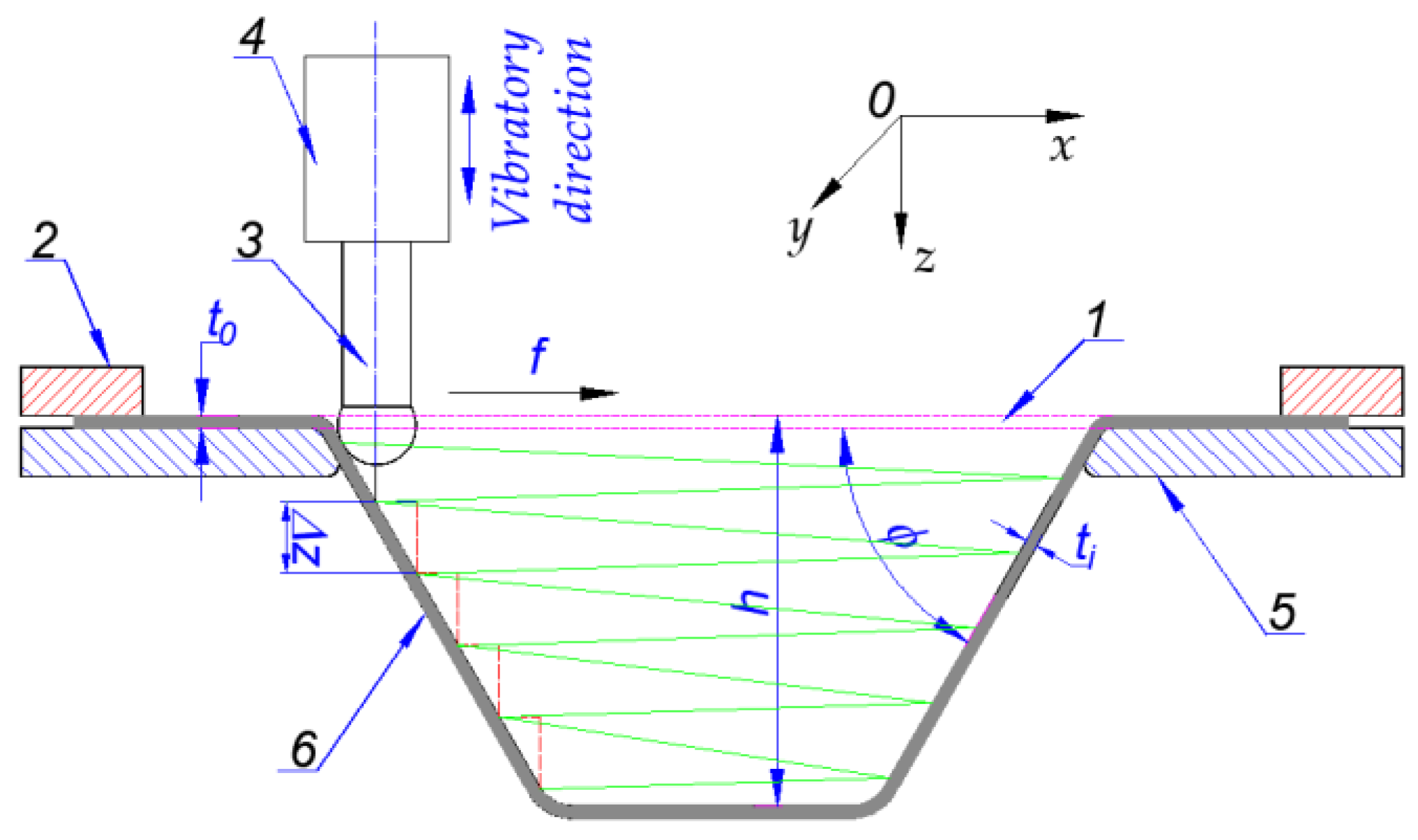
2. Materials and Methods

Figure 1 presents the diagram of the UISF operation. To constrain the workpiece of t0 thickness before the forming process, a blank holder and a back plate were used. The forming tool is clamped to an ultrasonic transducer to acquire vertical-direction vibrations. Depending on the depth h and angle ϕ of the shaping profile, the trajectory of the tool is selected [23]. Small step depth Δz and feed rate f are selected for programming the movement of the tool. To reduce the contact surface between the forming tool and the plate, different diameters of the tool’s hemispherical-head, ranging from 5 to 20 mm, are used for evaluation [24,25]. After the UISF process, thicknesses of the product at forming areas will be thinner (ti < t0). Since the rotation of the tool has no effect on the forming forces [26,27,28], the tool in this study selected was fixed in all experiments.
The configuration of the experimental system is presented in Figure 2a. A modified- vertical milling machine (VHR-AP CNC) (Shizuoka, Japan) was used for the experiment. A 9257B dynamometer (Kistler, Winterthur, Switzerland) was used to measure the deformation forces in three directions during forming. Ultrasonic vibrations were generated at a 20 kHz frequency using a Chinese ultrasonic generator and a transducer (Herrmann, Walsrode, Germany). The forming tool, made from C45 steel, has a diameter d of 16 mm.
To maximize the vibration amplitude at the tool’s tip, its structure was carefully designed. Wave propagation theory was applied to determine an appropriate tool size compatible with fixed frequency of the transducer [20,21]. The V-I testing method was selected to inspect the resonant frequency for the system. Figure 2b illustrates the scanning resonant frequency results using the given transducer. During the UISF process, ultrasonic vibration was manually controlled to inspect its influence on forming forces. The NI SignalExpress software (version 2015) and a DAQ NI-6210 (National Instruments, Austin, TX, USA) were used to collect data (1000 times per second) concerning the force and the current.
The samples used in the experiment are Al 5052 aluminum alloy sheets with thicknesses of 0.5 mm and 1.0 mm, respectively. These sheets are cut in a square shape, with dimensions of 240 mm × 240 mm. The deformation tool feed rates are investigated at values of 1200–1600–2000–2400 mm/min, respectively. All experiments were performed under oil lubrication conditions. The step depth Δz, forming depth h, and wall angle ϕ (as depicted in Figure 1) are fixedly selected at 0.5 mm, and 20 mm, and 45°, respectively. The forming tool feed trajectory, constant for all experiments, is spiral, as depicted in Figure 1.
During the experimental process, the forming can be considered to be carried out using the conventional ISF process when the current is supplied to the transducer in turning-off mode. Conversely, when current is supplied to the transducer in turning-on mode, the shaping is performed by the UISF process.

3. Results and Discussion
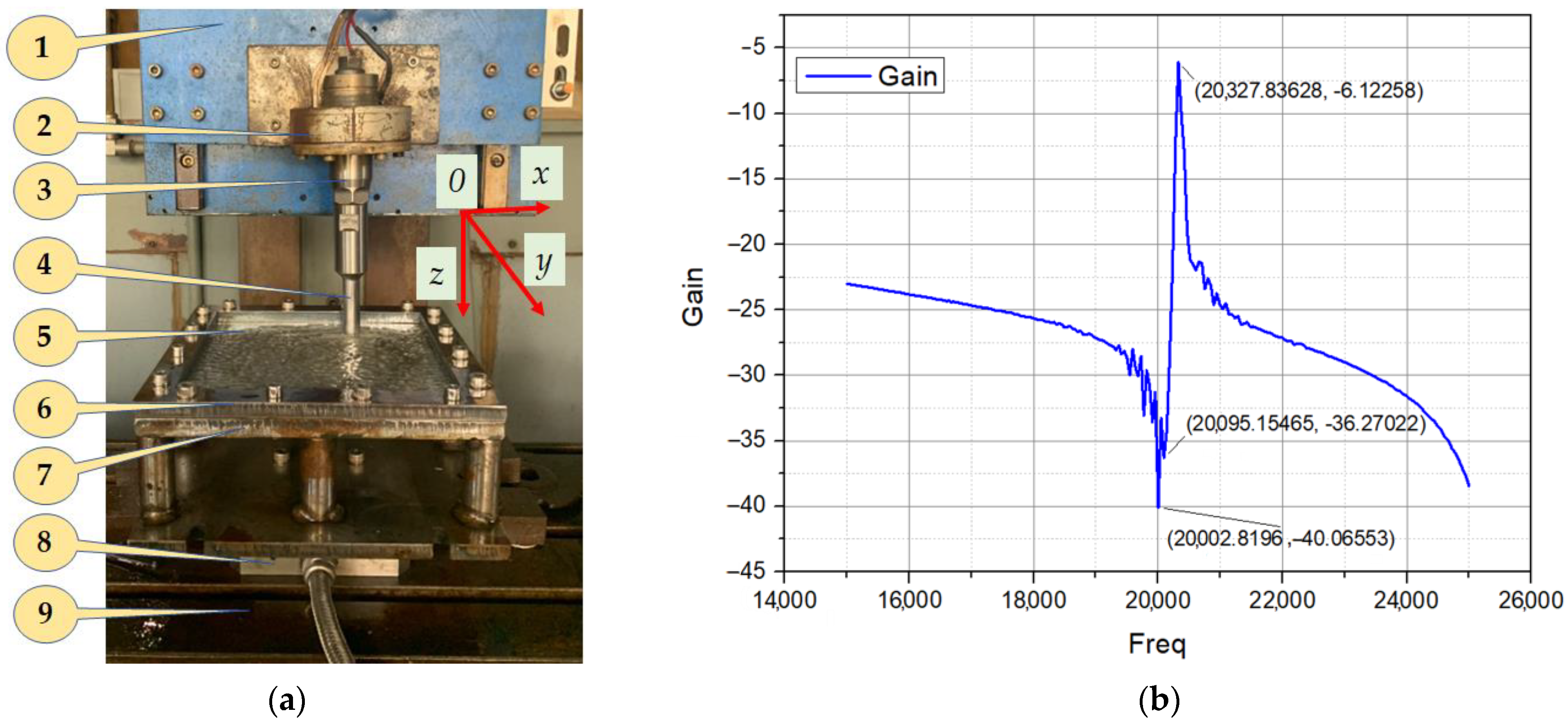
3.1. Forming Forces

Figure 3 and Figure 4 present diagrams of forming forces and current supply for the transducer, for 0.5 mm- and 1.0 mm-thick plates, respectively. According to the varied current supplied to the transducer, the force components Fx, Fy, and Fz are also changed accordingly.
The results from the experiments show that the component vertical force Fz is significantly greater than the component horizontal forces Fx and Fy. When the deformation depth reaches about 15 mm (for both sheet thicknesses), the deformation component force Fz stabilizes and does not increase. This can be explained by the balance between strain hardening and sheet thinning.
The results from Figure 3 and Figure 4 indicate that, when assisted by ultrasonic vibration, the forming forces are strongly reduced. For a plate with a thickness of 0.5 mm, the force components are reduced by about 50%. For a plate with a thickness of 1.0 mm, the force reduction effect is greater; especially as the force components according to Fx and Fy reach approximately 75%. In addition, when reaching a forming depth of about 15 mm, the effect of reducing the deformation force of the ultrasonic vibration becomes stable.
These results also show that the force components during forming via the UISF process tend to decrease when the power supply time to the transducer is extended. The decreasing trend is more obvious when the plate thickness is larger. This can be explained by the thermal effect generated during the forming process under the influence of ultrasonic vibrations because of volume effects [29]. When the plate thickness is large, the heat loss by convective heat exchange is smaller. Heat generation by ultrasonic vibration makes the movement of the dislocations easier, and the material is more easily deformed [17]. Furthermore, the ultrasonic vibration also reduces the stress in the direction of the dislocation [30]. Therefore, the forming forces from the UISF process are smaller than those of the ISF process. In addition, many previous studies have shown that ultrasonic vibrations interrupt the contact region between the tool and the workpiece, hence reducing the contact friction [29]. This also contributes to reducing the horizontal force components Fx and Fy.
The results of the average reduction in the forming forces RFx (%), RFy (%), and RFz (%) and standard deviations (sd) at different feed rates are also illustrated in Table 1 and Table 2 for 0.5 mm-thickness and 1.0 mm-thickness plates, respectively. For each tool feed rate, the experiment was performed five times. With an expected standard deviation of less than 5%, it can be affirmed that the experimental results ensure statistical significance.
The reductions in the average forming forces RFx (%), RFy (%), and RFz (%) at different feed rates are also shown in Figure 5 for plates with thicknesses of 0.5 mm and 1.0 mm, respectively. It indicates that when the tool feed rate is large, the effectiveness of reducing deformation force Fz thanks to the ultrasonic vibration is reduced. Similar trends are also observed for the forces Fx and Fy when forming large-thickness plates. However, with a small plate thickness, when increasing the feed rate, the effectiveness of reducing the forces Fx and Fy increases.

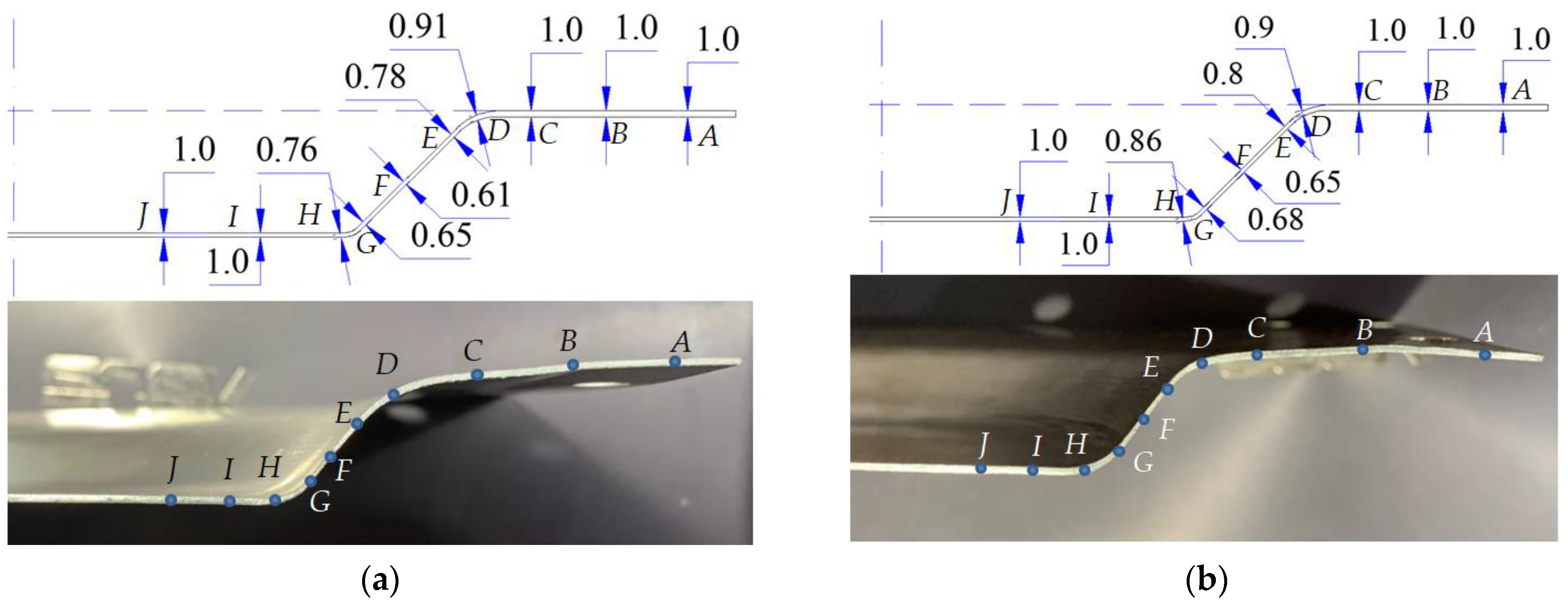
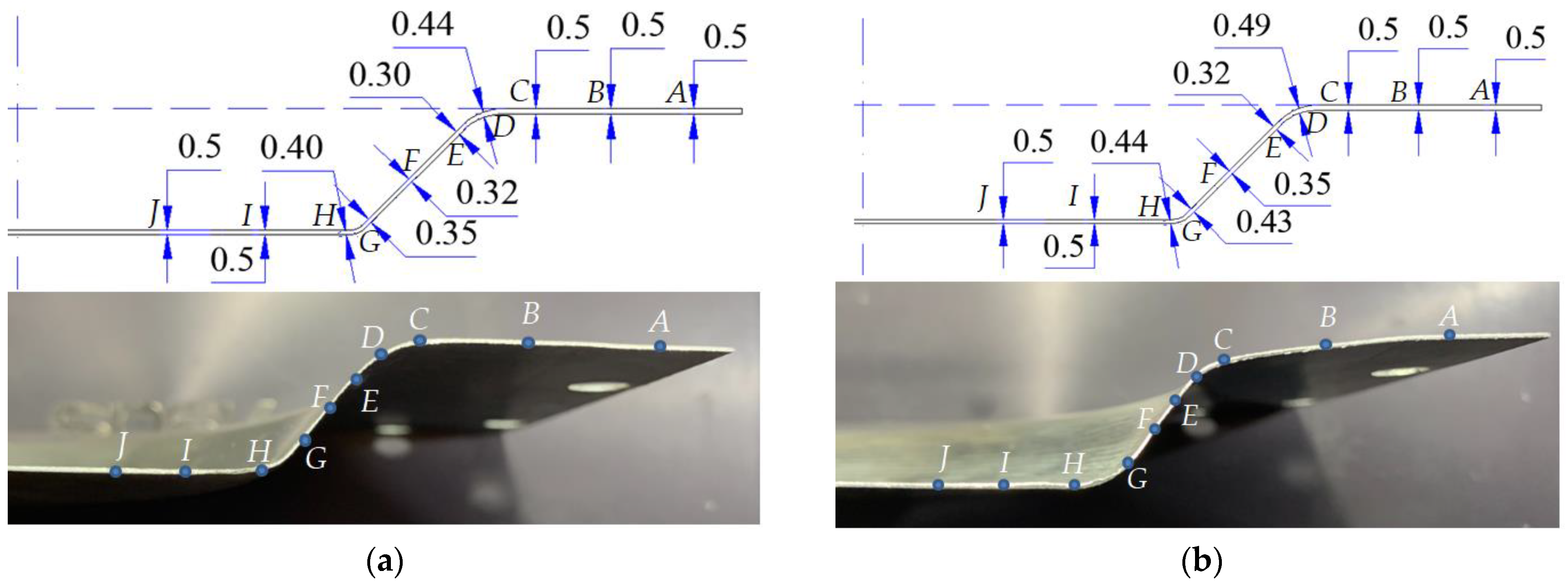
3.2. Thickness Distributions

Figure 6 and Figure 7 present the product wall thickness distribution results after forming with the conventional ISF process and the ultrasonic-assisted ISF process. The measurements were conducted using a caliper.
Both types of plates show similar thickness distributions. The deformation zone (on the wall, between the bottom surface and the clamping flange) is tensile and thins the most. Therefore, the thickness in this region is usually the smallest. For both types of sheet thickness, due to the assistance of the ultrasonic vibration, the thickness distribution is more uniform. In other words, the thinning occurs more intensely when machining with the conventional ISF process. However, it can be clearly seen that the thickness distribution on the thicker plate has a larger difference. This can be explained by the greater heat generated in thicker plates, causing the material to soften more intensely. Therefore, deformation in this region occurs more easily. This result is quite similar to recent studies on the extremely deformable materials [8,13,22,31,32,33,34].

4. Conclusions

This work involved forming Al 5052 aluminum alloy plates with different thicknesses of 0.5 mm and 1.0 mm. A series of ISF experiments with and without ultrasonic-assisted vibration, using 0.5 mm step depth size and different feed rates of 1200–1600–2000–2400 mm/min, were used to form 20 mm-depth and 45° angle truncated cones. Several remarks can be concluded as follows:
-
The deformation forces, including Fx, Fy, and Fz, tend to strongly decrease during the forming process with the assistance of ultrasonic vibration. When a certain forming depth is reached, this effect of reducing deformation force is relatively stable.
-
For different feed rates, ranging from 1200 to 2400 mm/min, the speed is inversely proportional to the effectiveness of reducing the main deformation force Fz due to the ultrasonic vibration.
-
The thickness distribution of the plate when forming via the UIF process is more uniform than that of the conventional ISF process.
However, this study also has a weakness in that it cannot demonstrate the relationship between the forming depth h and forming force components due to limitations in the measuring equipment. Further research should investigate, evaluate, and predict the surface roughness and wave, spring back and pillow phenomena, and mechanical properties of products formed via the UISF process.

Author Contributions

Conceptualization, K.-T.H. and T.-L.L.; methodology, K.-T.H. and N.-T.L.; software, K.-T.H.; validation, K.-T.H.; formal analysis, T.-L.L. and N.-T.; investigation, N.-T.L., T.-L.L. and N.-T.; resources, K.-T.H.; writing—original draft preparation, N.-T.L. and T.-L.L.; writing—review and editing, K.-T.H.; visualization, N.-T.L.; project administration, K.-T.H.; funding acquisition, K.-T.H. All authors have read and agreed to the published version of the manuscript.

Funding

This research received no external funding.

Institutional Review Board Statement

Not applicable.

Informed Consent Statement

Not applicable.

Data Availability Statement

Data are contained within the article.

Acknowledgments

The authors would like to express their thanks to Thai Nguyen University of Technology, Vinh University of Technology Education, and TUETECH University for their support during this study.

Conflicts of Interest

The authors declare no conflicts of interest.

References

  1. Bhasker, R.S.; Kumar, Y. Process capabilities and future scope of Incremental Sheet Forming (ISF). Mater. Today Proc. 2023, 72, 1014–1019. [Google Scholar] [CrossRef]
  2. Agrawal, M.K.; Singh, P.; Mishra, P.; Deb, R.K.; Mohammed, K.A.; Kumar, S.; Kumar, G. A brief review on the perspective of a newer incremental sheet forming technique and its usefulness. Adv. Mater. Process. Technol. 2023, 10, 506–516. [Google Scholar] [CrossRef]
  3. Oleksik, V.; Trzepiecinski, T.; Szpunar, M.; Chodola, L.; Ficek, D.; Szczesny, I. Single-Point Incremental Forming of Titanium and Titanium Alloy Sheets. Materials 2021, 14, 6372. [Google Scholar] [CrossRef] [PubMed]
  4. Erisov, Y.; Nikolaenko, A.; Petrov, I.; Surudin, S.; Kolsanov, A. Influence of the process parameters of incremental forming of personified implants of the cranial bones on their geometry. J. Phys. Conf. Ser. 2022, 2373, 032011. [Google Scholar] [CrossRef]
  5. Ullah, S.; Li, Y.; Li, X.; Xu, P.; Li, D. A review on the deformation mechanism and formability enhancement strategies in incremental sheet forming. Arch. Civ. Mech. Eng. 2022, 23, 55. [Google Scholar] [CrossRef]
  6. Patel, D.; Gandhi, A. A review article on process parameters affecting Incremental Sheet Forming (ISF). Mater. Today Proc. 2022, 63, 368–375. [Google Scholar] [CrossRef]
  7. Lu, H.; Liu, H.; Wang, C. Review on strategies for geometric accuracy improvement in incremental sheet forming. Int. J. Adv. Manuf. Technol. 2019, 102, 3381–3417. [Google Scholar] [CrossRef]
  8. Jeswiet, J.; Micari, F.; Hirt, G.; Bramley, A.; Duflou, J.; Allwood, J. Asymmetric Single Point Incremental Forming of Sheet Metal. CIRP Ann. 2005, 54, 88–114. [Google Scholar] [CrossRef]
  9. Ullah, S.; Li, X.; Xu, P.; Li, Y.; Han, K.; Li, D. A toolpath strategy for improving geometric accuracy in double-sided incremental sheet forming. Chin. J. Aeronaut. 2023, 36, 468–479. [Google Scholar] [CrossRef]
  10. Li, Z.; He, S.; An, Z.; Gao, Z.; Lu, S. Multi-Objective Optimization of Dimensional Accuracy in Electric Hot Incremental Sheet Forming. Coatings 2023, 13, 923. [Google Scholar] [CrossRef]
  11. Thiery, S.; Zein El Abdine, M.; Heger, J.; Ben Khalifa, N. Closed-loop control of product geometry by using an artificial neural network in incremental sheet forming with active medium. Int. J. Mater. Form. 2020, 14, 1319–1335. [Google Scholar] [CrossRef]
  12. Wu, S.; Geng, P.; Ma, N.; Lu, F. Contact-induced vibration tool in incremental sheet forming for formability improvement of aluminum sheets. J. Mater. Res. Technol. 2022, 17, 1363–1379. [Google Scholar] [CrossRef]
  13. Ghafoor, S.; Li, Y.L.; Zhao, G.L.; Li, F.Y. Improving the formability during ultrasonic-assisted multi-stage incremental sheet forming. IOP Conf. Ser. Mater. Sci. Eng. 2022, 1270, 012002. [Google Scholar] [CrossRef]
  14. Sun, Y.; Lu, Z.; Li, C.; Wang, R.; Zhai, W. Study on the Springback Effect and Surface Property for Ultrasonic-Assisted Incremental Sheet Forming of Aluminum Alloy. Symmetry 2021, 13, 1217. [Google Scholar] [CrossRef]
  15. Li, Y.-L.; Wang, Z.-J.; Zhai, W.-D.; Cheng, Z.-N.; Li, F.-Y.; Li, X.-Q. The influence of ultrasonic vibration on parts properties during incremental sheet forming. Adv. Manuf. 2021, 9, 250–261. [Google Scholar] [CrossRef]
  16. La, N.-T.; Ngo, Q.-H.; Vu, V.-D.; Mai, T.-H.; Ho, K.-T. Optimization of Ultrasonic-Assisted Incremental Sheet Forming. Materials 2024, 17, 3170. [Google Scholar] [CrossRef]
  17. Cheng, Z.; Li, Y.; Li, J.; Li, F.; Meehan, P.A. Ultrasonic assisted incremental sheet forming: Constitutive modeling and deformation analysis. J. Mater. Process. Technol. 2022, 299, 117365. [Google Scholar] [CrossRef]
  18. Zhai, W.; Li, Y.; Cheng, Z.; Sun, L.; Li, F.; Li, J. Investigation on the forming force and surface quality during ultrasonic-assisted incremental sheet forming process. Int. J. Adv. Manuf. Technol. 2020, 106, 2703–2719. [Google Scholar] [CrossRef]
  19. Ho, K.-T.; La, N.-T.; Chu, N.-H.; Vu, N.-H.; Mai, T.-L. Applying Ultrasonic-Assisted Incremental Sheet Forming to Al 5052 Aluminum Alloy. Eng. Proc. 2023, 45, 8. [Google Scholar] [CrossRef]
  20. Vahdati, M.; Mahdavinejad, R.; Amini, S. Investigation of the ultrasonic vibration effect in incremental sheet metal forming process. Proc. Inst. Mech. Eng. Part B J. Eng. Manuf. 2015, 231, 971–982. [Google Scholar] [CrossRef]
  21. Amini, S.; Hosseinpour Gollo, A.; Paktinat, H. An investigation of conventional and ultrasonic-assisted incremental forming of annealed AA1050 sheet. Int. J. Adv. Manuf. Technol. 2017, 90, 1569–1578. [Google Scholar] [CrossRef]
  22. Ghafoor, S.; Li, Y.; Zhao, G.; Li, J.; Ullah, I.; Li, F. Deformation characteristics and formability enhancement during ultrasonic-assisted multi-stage incremental sheet forming. J. Mater. Res. Technol. 2022, 18, 1038–1054. [Google Scholar] [CrossRef]
  23. Li, Y.; Chen, X.; Liu, Z.; Sun, J.; Li, F.; Li, J.; Zhao, G. A review on the recent development of incremental sheet-forming process. Int. J. Adv. Manuf. Technol. 2017, 92, 2439–2462. [Google Scholar] [CrossRef]
  24. Le, T.-K.; Tran, D.-T.; Bui, N.-T.B.; Nguyen, T.-H.; Beltran-Carbajal, F. Effect of Ultrasonic Vibration on Forming Force in the Single-Point Incremental Forming Process. Shock Vib. 2023, 2023, 1565927. [Google Scholar] [CrossRef]
  25. Uheida, E.H.; Oosthuizen, G.A.; Dimitrov, D.M. Toward understanding the process limits of incremental sheet forming of titanium alloys. In Proceedings of the Proceedings of the Competitive Manufacturing, International Conference on Competitive Manufacturing (COMA’16), Stellenbosch, South Africa, 27–29 January 2016. [Google Scholar]
  26. Zhang, L.; Wu, C.; Sedaghat, H. Ultrasonic vibration–assisted incremental sheet metal forming. Int. J. Adv. Manuf. Technol. 2021, 114, 3311–3323. [Google Scholar] [CrossRef]
  27. Li, J.; Li, Y.; Yuan, H.; Cheng, Z.; Yu, Y.; Ghafoor, S.; Li, F. Multi-stage finite element modeling of the deformation behavior during ultrasonic-assisted incremental sheet forming. J. Comput. Sci. 2023, 72, 102077. [Google Scholar] [CrossRef]
  28. Bishnoi, P.; Chandna, P. Formability of Aluminum Alloys During Single Point Incremental Forming. Int. J. Manuf. Mater. Mech. Eng. 2022, 12, 26. [Google Scholar] [CrossRef]
  29. Zhai, J.; Guan, Y.; Liu, Y.; Chen, F.; Lin, J. Macroscopic mechanism of ultrasonic vibration in ultrasonic-assisted metal forming. J. Mater. Res. Technol. 2023, 24, 7852–7864. [Google Scholar] [CrossRef]
  30. Li, Y.; Zhai, W.; Wang, Z.; Li, X.; Sun, L.; Li, J.; Zhao, G. Investigation on the material flow and deformation behavior during ultrasonic-assisted incremental forming of straight grooves. J. Mater. Res. Technol. 2020, 9, 433–454. [Google Scholar] [CrossRef]
  31. Ham, M.; Jeswiet, J. Single Point Incremental Forming and the Forming Criteria for AA3003. CIRP Ann. 2006, 55, 241–244. [Google Scholar] [CrossRef]
  32. Shukur, J.; Shbeeb, A.; Saad, W. Analysis of the process parameters effect on the thickness distribution and thinning ratio in single point incremental forming process. J. Mech. Eng. Res. Dev. 2020, 43, 374–382. [Google Scholar]
  33. Nikhil Bari, S.K. Experimental investigation on thinning and forming force acting on multi-stage single point incremental forming. Mater. Res. Proc. 2023, 25, 53–60. [Google Scholar]
  34. Huang, H.; Yue, M.; Tang, Q.; Peng, B.; Tang, X.; Fang, Q.; Chen, G. Change in geometry size and thinning rate in single-point incremental forming process of TA1 sheet: Evaluation method and finite element analysis. Int. J. Adv. Manuf. Technol. 2023, 125, 2743–2758. [Google Scholar] [CrossRef]
Figure 1. Typical diagram of the UISF process: (1) initial sheet; (2) blank holder; (3) forming tool; (4) ultrasonic transducer; (5) backplate; (6) workpiece.
Engproc 75 00024 g001
Figure 2. Setup of the experiment: (a) a real configuration and (b) scanning resonant frequency results of the system. (1) CNC machine’s head; (2) clamp for forming tool; (3) transducer; (4) forming tool; (5) workpiece; (6) holder; (7) backplate; (8) dynamometer; (9) table bed of CNC machine.
Engproc 75 00024 g002
Figure 3. Forming forces Fx, Fy, and Fz corresponding to the current supply to the transducer i (A) for forming 0.5 mm thick plate at conditions f = 2000 mm/min; Δz = 0.5 mm: (a) full forming process; (b) a part from 240 s to 340 s.
Engproc 75 00024 g003
Figure 4. Forming forces Fx, Fy, and Fz corresponding to the current supply to the transducer i (A) to form 1.0 mm thick plate at conditions f = 2400 mm/min; Δz = 0.5 mm: (a) full forming process; (b) a part from 200 s to 250 s.
Engproc 75 00024 g004
Figure 5. Error bar plots of average reduction in forming forces RFx, RFy, and RFz (%): (a) thickness of 0.5 mm; (b) thickness of 1.0 mm.
Engproc 75 00024 g005
Figure 6. Thickness distribution for plates of 1.0 mm at a feed rate of 2400 mm/min: (a) forming via conventional ISF; (b) forming via UISF.
Engproc 75 00024 g006
Figure 7. Thickness distribution for plates of 0.5 mm at a feed rate of 2400 mm/min: (a) forming via conventional ISF; (b) forming via UISF.
Engproc 75 00024 g007
Table 1. Results of the average of RFx (%), RFy (%), RFz (%), and standard deviations of plates 0.5 mm in thickness.
Feed Rate (mm/min)Average of RFx (%) and RFy (%)Average of RFz (%)
RFx (%) and RFy (%)Upper of sdLower of sdRFz (%)Upper of sdLower of sd
120050.0%3.1%2.3%59.2%3.3%2.9%
160058.5%4.2%2.9%57.1%4.4%3.1%
200060.2%2.5%3.6%53.0%3.9%4.2%
240062.5%3.2%4.5%50.1%3.5%3.2%
Table 2. Results of average of RFx (%), RFy (%), RFz (%), and standard deviations of plates 1.0 mm in thickness.
Feed Rate (mm/min)Average of RFx (%) and RFy (%)Average of RFz (%)
RFx (%) and RFy (%)Upper of sdLower of sdRFz (%)Upper of sdLower of sd
120075.0%3.7%4.3%54.1%4.5%3.9%
160074.0%4.4%3.2%50.0%3.4%3.3%
200073.2%3.5%2.6%49.8%4.5%2.6%
240071.5%4.1%3.5%48.5%3.6%3.5%
Disclaimer/Publisher’s Note: The statements, opinions and data contained in all publications are solely those of the individual author(s) and contributor(s) and not of MDPI and/or the editor(s). MDPI and/or the editor(s) disclaim responsibility for any injury to people or property resulting from any ideas, methods, instructions or products referred to in the content.

