Proceeding Paper

Optimizing Impact Toughness in 3D-Printed PLA Structures Using Hilbert Curve and Honeycomb Infill Patterns †

Faculty of Mechanical Engineering, Ghulam Ishaq Khan Institute of Engineering Sciences and Technology, Swabi 23640, Pakistan
*
Authors to whom correspondence should be addressed.
Presented at the 4th International Conference on Advances in Mechanical Engineering (ICAME-24), Islamabad, Pakistan, 8 August 2024.
Eng. Proc. 2024, 75(1), 27; https://doi.org/10.3390/engproc2024075027
Published: 24 September 2024

Abstract

:
This study investigates the impact toughness of 3D-printed PLA structures with Hilbert curve and honeycomb infill patterns at various raster angles. Samples were fabricated using Fused Deposition Modeling (FDM) and tested for impact energy absorption using the Charpy test. The results showed that specimens printed at a 90° raster angle exhibited the highest impact absorption. Hilbert curve patterns demonstrated 20.6% less energy absorption than plain samples with 40% infill and 11% higher energy absorption than plain samples with 100% infill, highlighting the significant role of material utilization in enhancing structural integrity.

1. Introduction

Modern manufacturing methods are critically important for designing and producing high-strength structures across various engineering sectors, including sports, automotive, biomedical, packaging, and civil engineering [1,2]. Consequently, extensive research has been conducted to develop lightweight structures with enhanced strength and impact resistance. Designing and manufacturing these resilient structures presents significant challenges for engineers and researchers, who must ensure that the components meet stringent design requirements [3]. The flexibility of the Fused Deposition Modeling (FDM) process, which allows for the creation of diverse structural topologies, addresses this issue by enabling the printing of various infill densities and patterns to optimize structural performance [4].
Initially, FDM was primarily used for prototyping, but advancements in manufacturing technologies have expanded its applications to include the production of load-bearing components capable of withstanding higher strain rates [5]. The layout of raster angles in the additive manufacturing process in terms of structures significantly influences the mechanical properties of components, as reported by G. Alaimo et al. Key process parameters such as infill density, build orientation, and infill patterns are crucial in determining the functional properties of FDM-manufactured components [6].
Various techniques and methods have been used to analyze the impact toughness of 3D-printed objects. O. S. Es-Said et al. [7] discovered that parts with raster orientations aligned with the loading axis had higher tensile and bending stiffness compared to other orientations. Tsouknidas et al. [8] investigated how layer height affects the energy dissipation characteristics of printed PLA structures, finding that higher layer heights increased the risk of premature failures due to greater stress concentrations during impact loading. A study investigating energy absorption at various infill densities was carried out by Tanveer et al. [9], who determined that the impact properties of PLA specimens are directly proportional to infill density.
Oguz Tunçel [10] utilized the Taguchi method and ANOVA for the optimization and analysis of 3D-printed objects. The optimized process parameters, i.e., print speed and infill density, improved impact strength by 1.39%, while Charpy impact strength results varied within a range of 9.7. Hafiz Ahmed et al. [11] demonstrated that Fused Filament Fabrication (FFF) technology enhances material performance, surpassing conventional polymer processing techniques. They varied parameters such as layer thickness, raster angle, and infill density to optimize and assess impact toughness. Dakhil et al. [12] found that the hexagon honeycomb infill pattern generally provided the highest impact strength among the tested patterns for 3D-printed PLA polymers. This suggests the geometric arrangement of the hexagon pattern significantly enhances the material’s impact resistance. The study highlights the importance of considering both infill density and pattern to optimize the impact strength of 3D-printed PLA.
Research indicates that increasing infill density enhances impact absorption capacity. The literature survey presented in this study was mainly focused on optimizing the process parameters and some infill patterns. However, further research is needed to determine the optimal infill pattern and density for maximizing material usage for impact resistance. This study aims to (i) manufacture samples with optimal infill patterns and infill density and (ii) assess impact energy absorption by utilizing material with high energy absorption using Charpy tests. Models were initially created with Hilbert curve and honeycomb infill patterns at 40% infill density with reference to research conducted by Hafiz Ahmad et al. [11]. Hilbert curve is a new type of infill pattern that has recently been introduced, while honeycomb is the best performing pattern. The samples were 3D printed and tested with the Charpy impact method, comparing 100% and 40% infill densities. The results show that the energy absorption capability of the Hilbert curve infill is almost equivalent to that of samples printed at 100% infill density, despite using 60% less material.

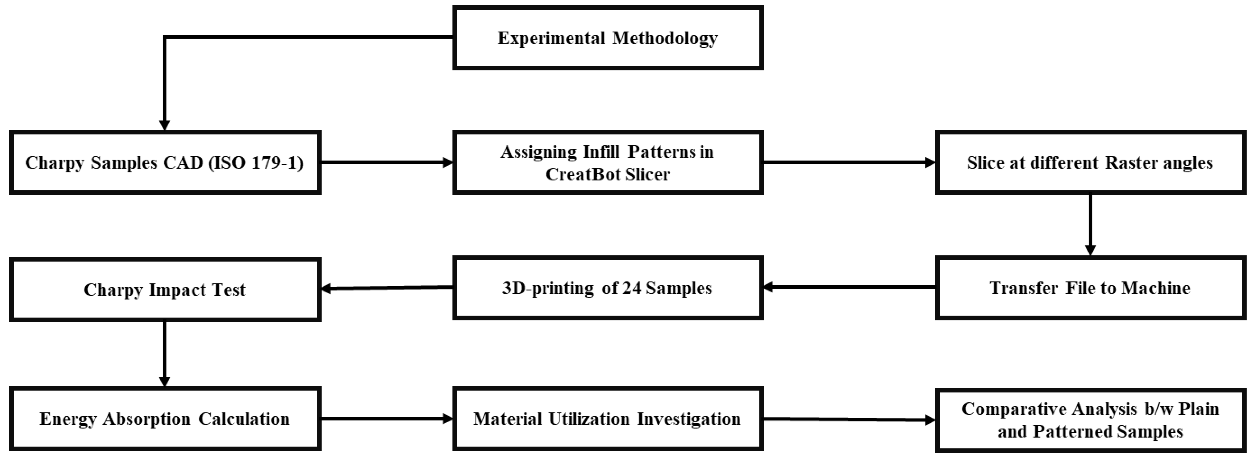
2. Materials and Methods

This research focused on two key objectives. First, a 3D model of the specimen was created according to the ISO 179 standard (https://www.iso.org/standard/84393.html, accessed on 23 September 2024) using commercial software, specifically Solid-Works (https://www.solidworks.com/, accessed on 23 September 2024). This model was then fabricated using a CreatBot F430 3D printer (Zhengzhou, Henan, China) with two different infill patterns: honeycomb and Hilbert curve. Polylactic acid (PLA) Plus was used as the 3D printing material to investigate its impact properties. Additionally, various raster angles were employed during the 3D printing process. The specimens were subjected to impact testing to examine the effects of different raster angles and infill patterns on mechanical properties such as energy absorption and failure modes. The impact tests were conducted using a Shimadzu Charpy impact testing machine (Shimadzu, Kyoto, Japan), and subsequent calculations were performed to determine the impact energy. The test plan consisted of additively manufacturing three samples for each infill pattern at three different raster angles and comparing them with the corresponding samples with 100% infill to justify the high energy absorption and material utilization. The detailed methodology of the study is illustrated in Figure 1.

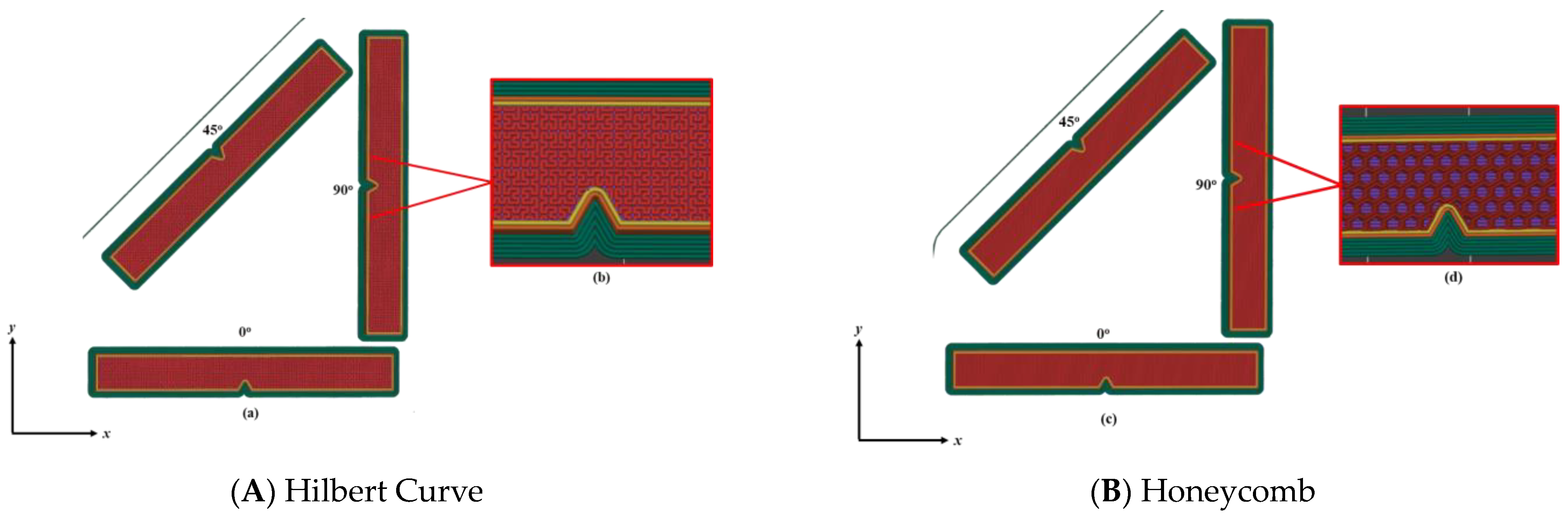
2.1. Manufacturing Method
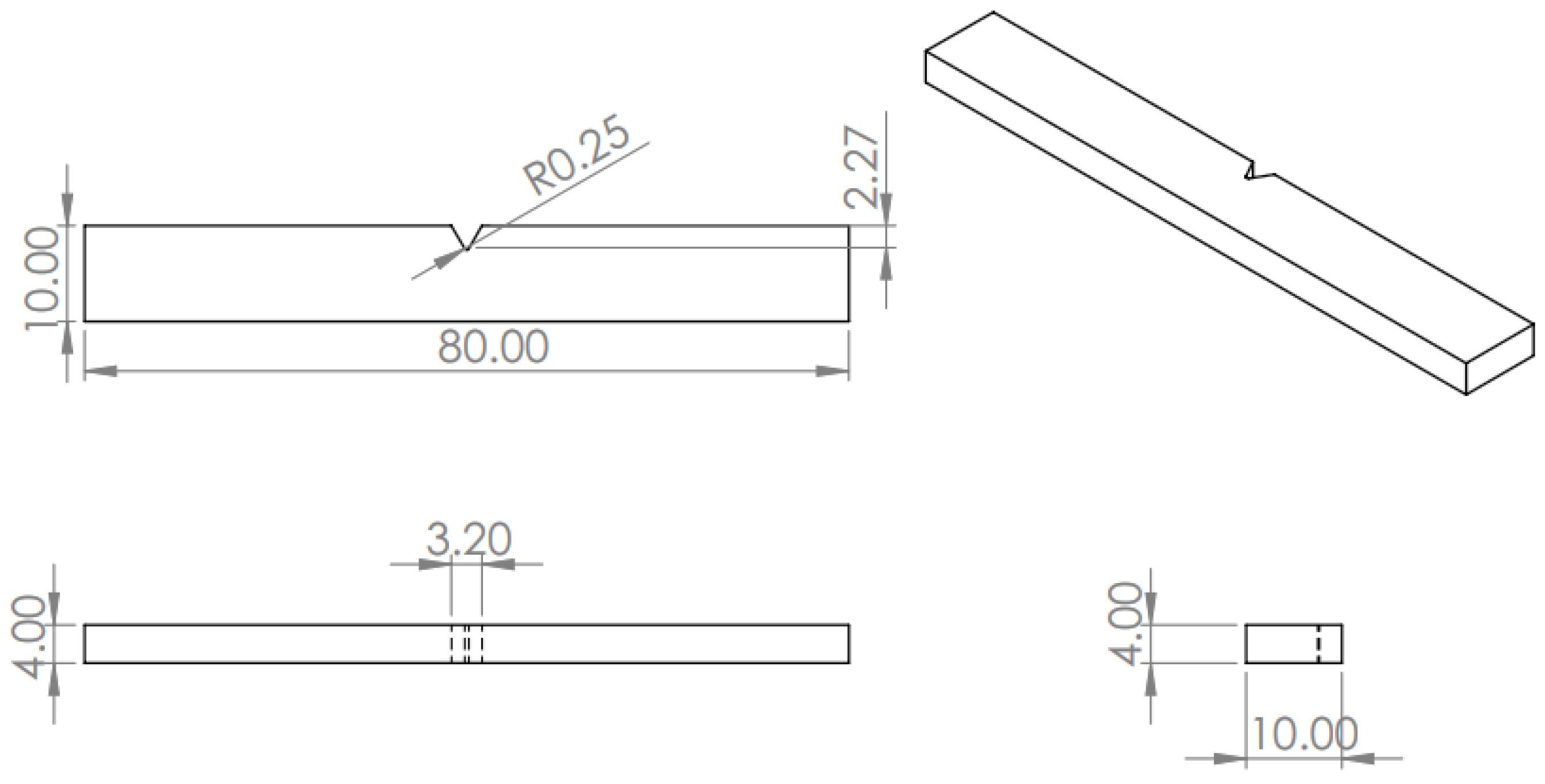
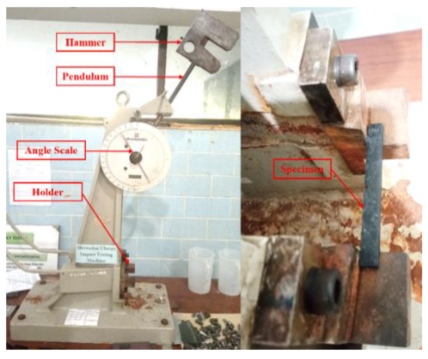
The 3D model of the impact specimen was designed following the ISO 179 standard (Figure 2) using SolidWorks. Twenty-four specimens were selected based on combinations of infill density and pattern were fabricated using a CreatBot F430 3D-printer. The infill density was kept at 40% while the Hilbert curve and honeycomb infill pattern were applied as illustrated in Figure 3a. The top layer of the Hilbert sample was also printed using the Hilbert curve pattern, as the slicing method supports this infill pattern for the topmost layer as shown in Figure 3b. In contrast, the honeycomb pattern could not be used for the top layer because it only works up to 70% infill density, while the top layer of any manufactured part requires 100% infill. Therefore, the rectilinear pattern was chosen as a top layer to cover the honeycomb infill pattern as shown in Figure 3c,d. Moreover, the specimens were printed at three different raster angles, i.e., 0°, 45°, and 90°. The specimens were additively manufactured according to the process parameters presented in Table 1.

2.2. Charpy Test

After printing the impact testing samples according to the ISO-179-1 standard (https://www.iso.org/standard/84393.html, accessed on 23 September 2024), we tested them using a Shimadzu Charpy impact machine to determine the impact strength of the samples. The machine operated with a free fall angle of 151°, i.e., “α” (the angle after the drop is “β“), a hammer weight of 22.023 N, and a moment arm of 0.363 m. The cross-sectional area of the specimens at the notch was 2.99 × 10⁻⁵ m2. The schematic of the impact testing machine is illustrated in Figure 4.
Charpy   Impact   value = E A
E = W D ( c o s β c o s α )
where
  • E is the energy absorption;
  • W is the weight of the hammer;
  • D is the distance from the axis to the center of gravity/moment arm.
  • β is the angle after the hammer drop.
  • α is the angle before the hammer drop.

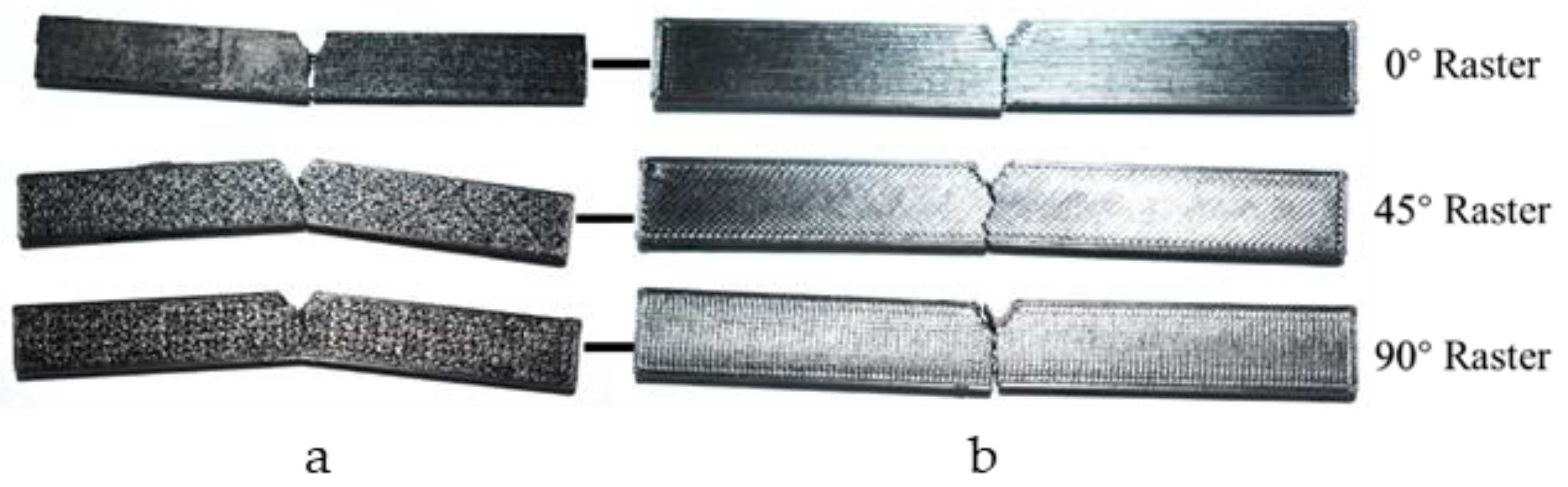
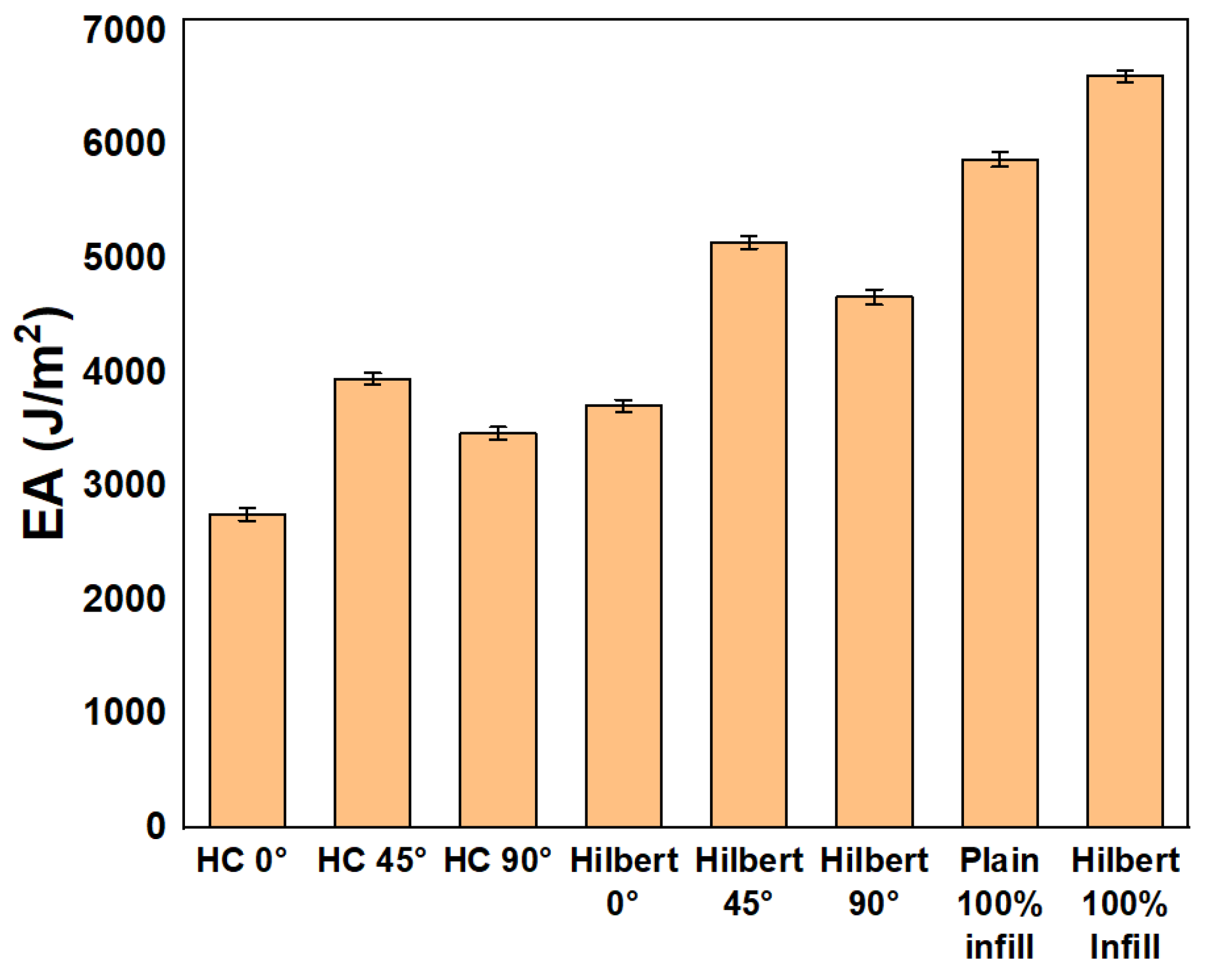
3. Results and Discussion

To assess impact energy absorption, four types of samples were printed according to the standard: plain plus Hilbert curve and honeycomb infill patterns printed at three different raster angles. All samples were subjected to Charpy impact testing using a Shimadzu Charpy impact testing machine with a free fall angle of 151°.

Effect of Raster Angles and Infill Patterns

This study compares impact energy absorption for three different raster angles of 0°, 45°, and 90° at 40% infill for honeycomb and Hilbert curve patterns, as shown in Table 2. It can be seen that raster angles significantly influence absorption values, as the samples printed along the shear direction yielded better results in the impact conditions. The highest absorption value for the honeycomb pattern was 3.95 KJ/m2 at a 45° raster and 40% infill. This result is consistent with the literature, indicating that at a 45° layer orientation, the part exhibits relatively ductile behavior. The failure visualization of samples, depicted in Figure 5, indicates that this raster angle has a significant impact on the failure of the impact specimen [10]. The figure shows that while the crack propagated more linearly in other patterns, the Hilbert curve pattern absorbed the impact energy and failed in an unusual manner. This is because the Hilbert curve pattern generally resembles auxetic behavior, and its lattice configuration allows it to absorb more energy [1]. Similarly, for the Hilbert curve pattern, with all other parameters held constant, the highest impact performance was 5.15 KJ/m2, also at a 45° raster. This finding further reinforces the significance of the statement regarding the superior impact absorption at this raster orientation.
The results at 100% infill were compared with those of the plain sample along with an error analysis with respect to standard deviation as shown in Figure 6. The bar graph depicts the energy absorption (EA) values for various configurations, with error bars representing the standard deviation. The configurations (Honeycomb) HC 0°, HC 45°, and HC 90° show relatively low standard deviations, indicating consistent measurements across samples. In contrast, the Plain 100% infill configuration exhibits a higher standard deviation, suggesting greater variability in energy absorption. Overall, the error bars demonstrate the reliability and consistency of the energy absorption measurements for each configuration.
The Hilbert curve pattern demonstrated comparable performance, achieving approximately 11.11% of the impact energy absorption of the plain sample at a 45° raster angle. This marks the remarkable performance of the Hilbert curve infill pattern at both 40% infill and 100% infill, making it a promising candidate in terms of lightweightness as well as at 100% infill. In contrast, the honeycomb pattern could not be printed at 100% infill due to its design limitation, which includes inclined lines and vertices that are not at 90°.The Hilbert curve pattern showcased remarkable impact absorption capabilities and the utilization of material where required, having the optimum strength.

4. Conclusions

This study designed impact specimens with Hilbert curve and honeycomb infill patterns to improve impact absorption at different raster angles. Samples were 3D printed with PLA Pro filament according to ISO 179-1 standards and tested for impact toughness. The results showed that specimens printed at a 90° raster angle had the highest impact absorption. The Hilbert curve samples demonstrated 20.6% higher energy absorption compared to plain samples with 40% infill, highlighting the importance of material utilization in structural integrity. Additionally, the Hilbert curve samples absorbed 11% more energy than plain samples with 100% infill, while honeycomb infill samples had the lowest impact absorption values. This renders the Hilbert curve a promising candidate in terms of infill patterns for lightweight and high energy absorption. These findings underscore the potential of optimized infill patterns to enhance the mechanical performance of 3D-printed structures, contributing to more efficient and resilient designs in engineering applications in diverse industrial sectors such as aerospace, medical implants, sports goods, etc.

Author Contributions

Conceptualization, B.A., A.N. and M.U.A.; methodology, S.U.; validation, M.W., S.U. and B.A.; formal analysis, M.A.A. and M.U.A.; investigation, B.A.; writing—original draft preparation, B.A and A.N.; writing—review and editing, B.A.; visualization, Q.A.A.; supervision, B.A. All authors have read and agreed to the published version of the manuscript.

Funding

This research received no external funding.

Institutional Review Board Statement

Not applicable.

Informed Consent Statement

Not applicable.

Data Availability Statement

Data will be made available upon request.

Acknowledgments

The authors want to acknowledge the Additive Manufacturing lab in the FME GIK Institute for providing the manufacturing facility and materials for manufacturing.

Conflicts of Interest

The authors declare no conflicts of interest.

References

  1. Ashfaq, B.; Hussain, G.; Khan, M.B.; Alkahtani, M.; Wei, H. A novel design of mono and bi-cells based hybrid auxetic structures and assessment of their compressive properties. J. Mater. Res. Technol. 2024, 28, 1620–1632. [Google Scholar] [CrossRef]
  2. Ashfaq, B.; Hussain, G.; Khan, M.B.; Ilyas, M. Mechanical characterization of innovative 3D-printed auxetic (NPR) structures: Role of considering anisotropy on accuracy of numerical modeling. Int. J. Adv. Manuf. Technol. 2024, 130, 4845–4859. [Google Scholar] [CrossRef]
  3. Parandoush, P.; Lin, D. A review on additive manufacturing of polymer-fiber composites. Compos. Struct. 2017, 182, 36–53. [Google Scholar] [CrossRef]
  4. Gohar, S.; Hussain, G.; Ilyas, M.; Ali, A. Performance of 3D printed topologically optimized novel auxetic structures under compressive loading: Experimental and FE analyses. J. Mater. Res. Technol. 2021, 15, 394–408. [Google Scholar] [CrossRef]
  5. Tobe, F. Design Aircraft Faster with FDM and 3D Printing. Design World Online. Available online: https://www.designworldonline.com/design-aircraft-faster-fdm-3d-printing/ (accessed on 8 January 2024).
  6. Alaimo, G.; Marconi, S.; Costato, L.; Auricchio, F. Influence of meso-structure and chemical composition on FDM 3D-printed parts. Compos. Part B Eng. 2017, 113, 371–380. [Google Scholar] [CrossRef]
  7. Es-Said, O.S.; Foyos, J.; Noorani, R.; Mendelson, M.; Marloth, R.; Pregger, B.A. Effect of layer orientation on mechanical properties of rapid prototyped samples. Mater. Manuf. Process. 2000, 15, 107–122. [Google Scholar] [CrossRef]
  8. Tsouknidas, A.; Pantazopoulos, M.; Katsoulis, I.; Fasnakis, D.; Maropoulos, S.; Michailidis, N. Impact absorption capacity of 3D-printed components fabricated by fused deposition modelling. Mater. Des. 2016, 102, 41–44. [Google Scholar] [CrossRef]
  9. Tanveer, M.Q.; Haleem, A.; Suhaib, M. Effect of variable infill density on mechanical behaviour of 3-D printed PLA specimen: An experimental investigation. SN Appl. Sci. 2019, 1, 1701. [Google Scholar] [CrossRef]
  10. Tunçel, O. Optimization of Charpy Impact Strength of Tough PLA Samples Produced by 3D Printing Using the Taguchi Method. Polymers 2024, 16, 459. [Google Scholar] [CrossRef] [PubMed]
  11. Ahmed, H.; Hussain, G.; Gohar, S.; Ali, A.; Alkahtani, M. Impact toughness of hybrid carbon fiber-PLA/ABS laminar composite produced through fused filament fabrication. Polymers 2021, 13, 3057. [Google Scholar] [CrossRef] [PubMed]
  12. Dakhil, G.Y.; Salih, R.M.; Hameed, A.M. The influence of infill pattern and infill density on the (tensile, flexural and impact) strength of 3D printed polymers. In AIP Conference Proceedings; AIP Publishing: Melville, NY, USA, 2022; Volume 2660. [Google Scholar]
Figure 1. Experimental methodology.
Engproc 75 00027 g001
Figure 2. Impact specimen dimensions.
Engproc 75 00027 g002
Figure 3. (A) Hilbert curve pattern (a) and top layer (b). (B) Honeycomb infill (c) with rectilinear top layer (d) covering.
Engproc 75 00027 g003
Figure 4. Charpy impact test setup.
Engproc 75 00027 g004
Figure 5. Failure visualization in impact samples: (a) Hilbert curve and (b) honeycomb.
Engproc 75 00027 g005
Figure 6. Comparison of sample performance.
Engproc 75 00027 g006
Table 1. Three-dimensional printing parameters.
Printing ParameterDefined Values
Layer height0.25 mm
Nozzle temp °C205
Build platform temp °C65
Printing speed35 mm/s
Infill density 40%
Table 2. Comparative analysis of impact specimens.
SamplesβDelta
(cosβ – cos α)
EA
(J)
EA
(KJ/m2)
% Diff
Plain vs. Infill
Honeycomb 0°149.8 ± 0.030.010 ± 0.020.082 ± 0.00252.76 ± 0.00552.93
Honeycomb 45°149.3 ± 0.010.014 ± 0.010.11 ± 0.00193.95 ± 0.02540.28
Honeycomb 90°149.5 ± 0.010.012 ± 0.010.10 ± 0.0023.47± 0.02040.90
Hilbert 0°149.4 ± 0.010.013 ± 0.010.11 ± 0.00153.71 ± 0.01243.88
Hilbert 45°148.8 ± 0.020.019 ± 0.010.15 ± 0.00125.15 ± 0.02212.39
Hilbert 90°149 ± 0.010.017 ± 0.010.14 ± 0.00254.67 ± 0.01220.60
Plain 100%148.5 ± 0.040.021 ± 0.030.17 ± 0.00415.88 ± 0.0540
Hilbert 100%148.2 ± 0.030.024 ± 0.030.19 ± 0.0026.61 ± 0.00511.11
Disclaimer/Publisher’s Note: The statements, opinions and data contained in all publications are solely those of the individual author(s) and contributor(s) and not of MDPI and/or the editor(s). MDPI and/or the editor(s) disclaim responsibility for any injury to people or property resulting from any ideas, methods, instructions or products referred to in the content.

