An On-Time Power-Aware Scheduling Scheme for Medical Sensor SoC-Based WBAN Systems


Abstract
:1. Introduction
2. On-Time Power-Aware Scheduler
2.1. System, Task, and Power-Mode Model
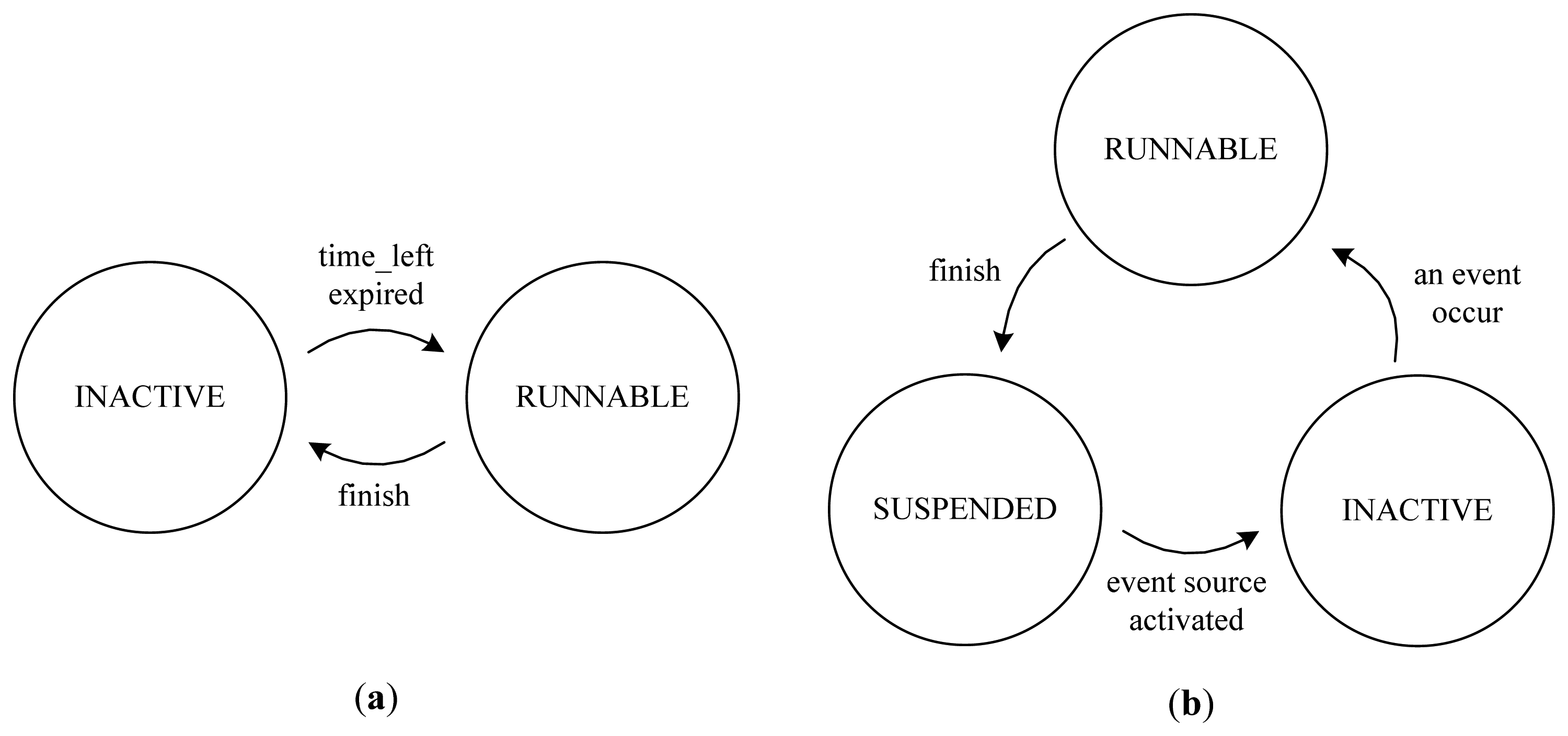
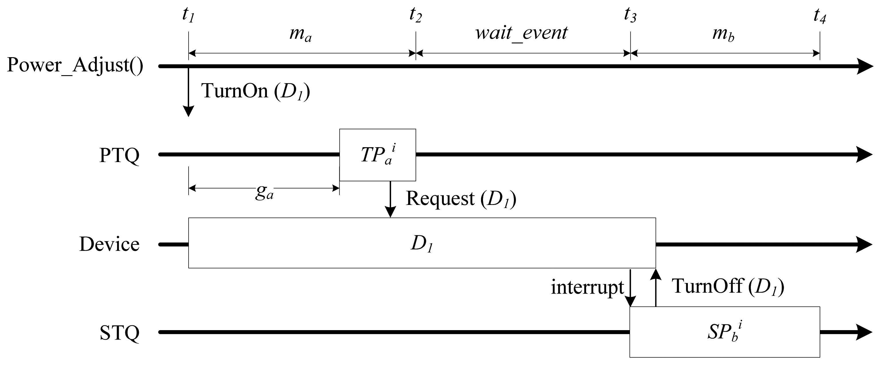
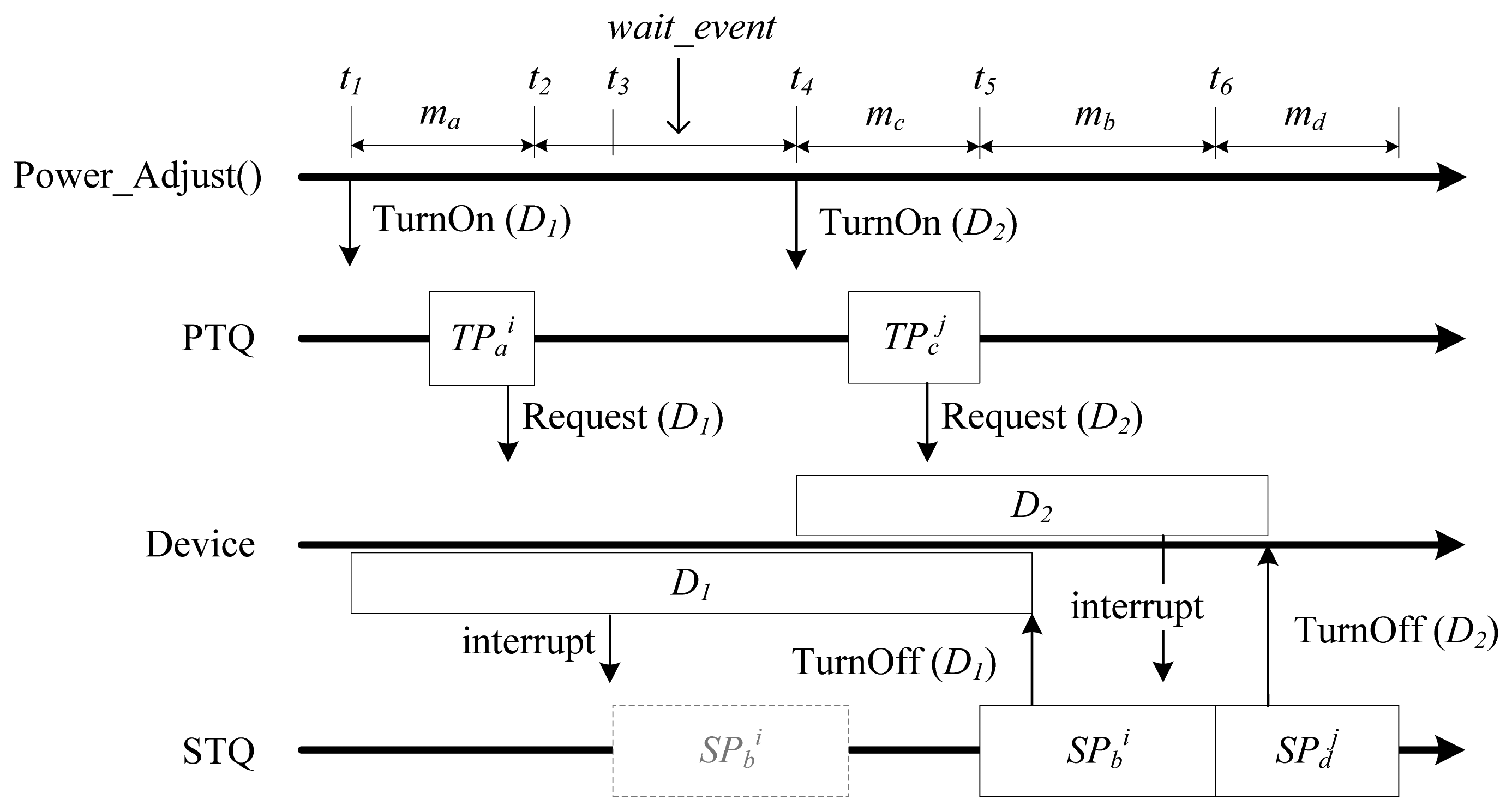
Notation 1: A periodic task and its nth periodic execution are denoted by TPi (o, p, w, g, m) and , respectively.where
Notation 2: A sporadic task and its nth execution are denoted by SPi (e, w, m) and , respectively.where
- There is no current execution of another task.
- There is no preceding RUNNABLE sporadic task.
- It is predicted that the execution of the sporadic task will not disturb the future execution of the coming periodic task, considering the WCET of the sporadic task.
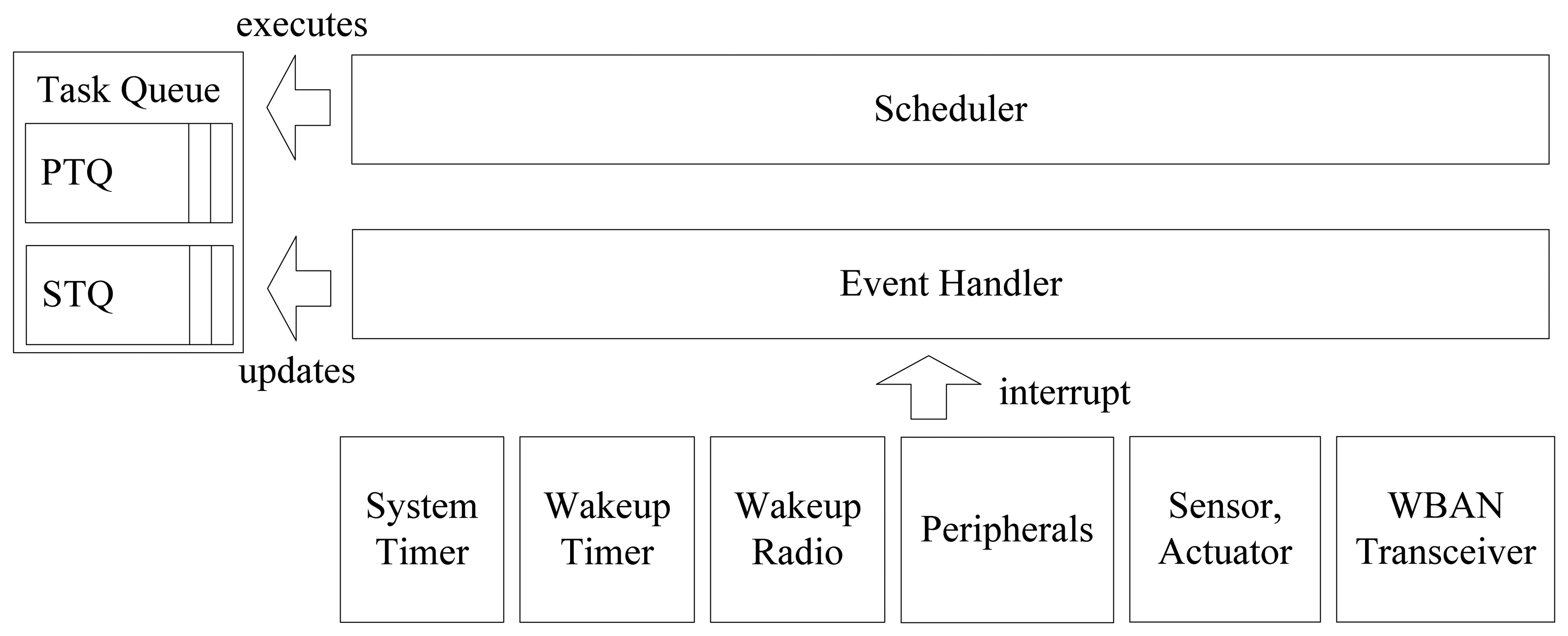
2.2. Design of an On-Time Power-Aware Scheduler
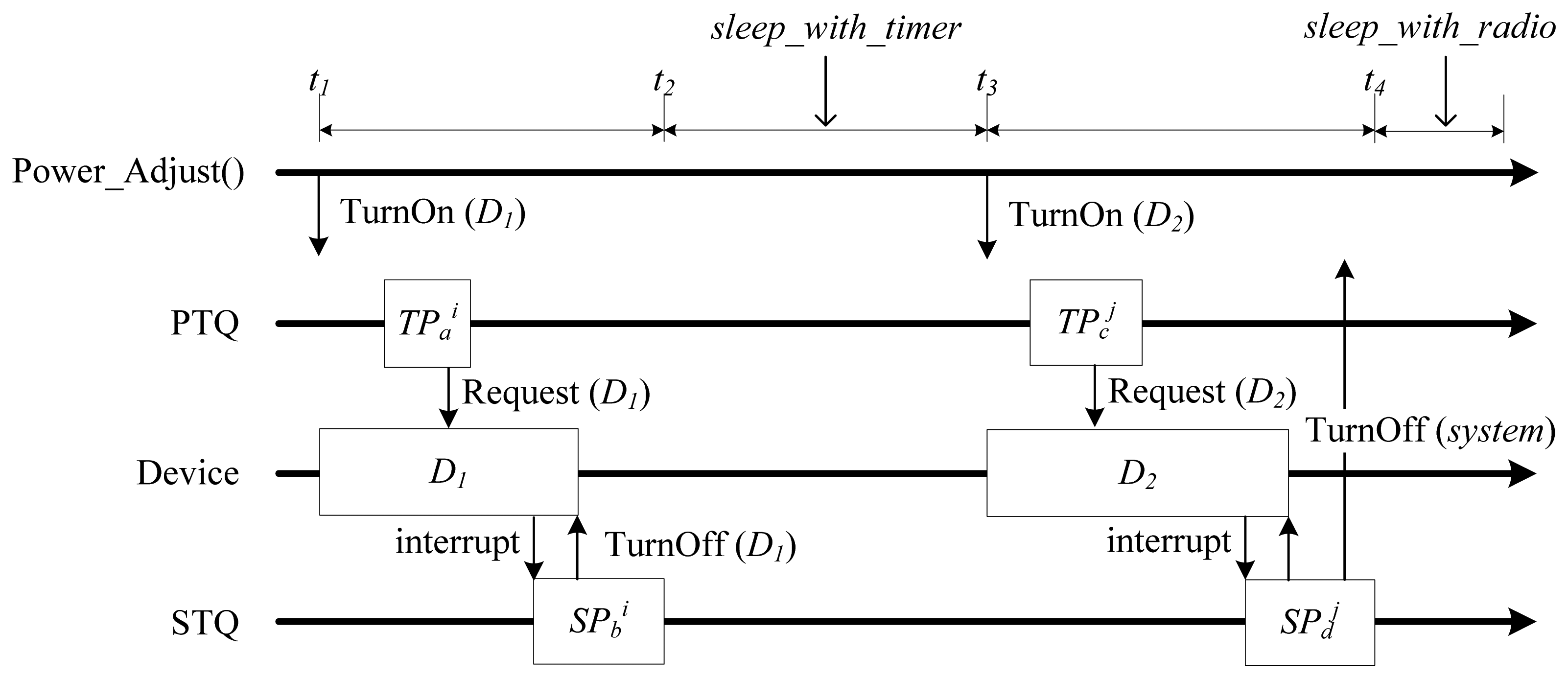
- If there is at least one RUNNABLE periodic task, set the task-power mode and call the task.
- Otherwise, if there is at least one RUNNABLE sporadic task, determine whether or not it can be scheduled immediately by comparing the WCET of this task and the time_left value of the next periodic task. If immediate scheduling is possible, set task-power mode and call the task. If it is not possible, set the system power mode as wait_event.
- If there is no RUNNABLE task but there is at least one INACTIVE sporadic task, set the power mode as wait_event.
- If there is no RUNNABLE or INACTIVE task,
- 4.1
- If there was a turn_off_system request from a task, set the power mode as sleep_with_radio.
- 4.2
- Else if the time left until the invocation of the next coming periodic task is larger than minSleepInterval, set the power mode as sleep_with_timer. Otherwise, set wait_event mode.
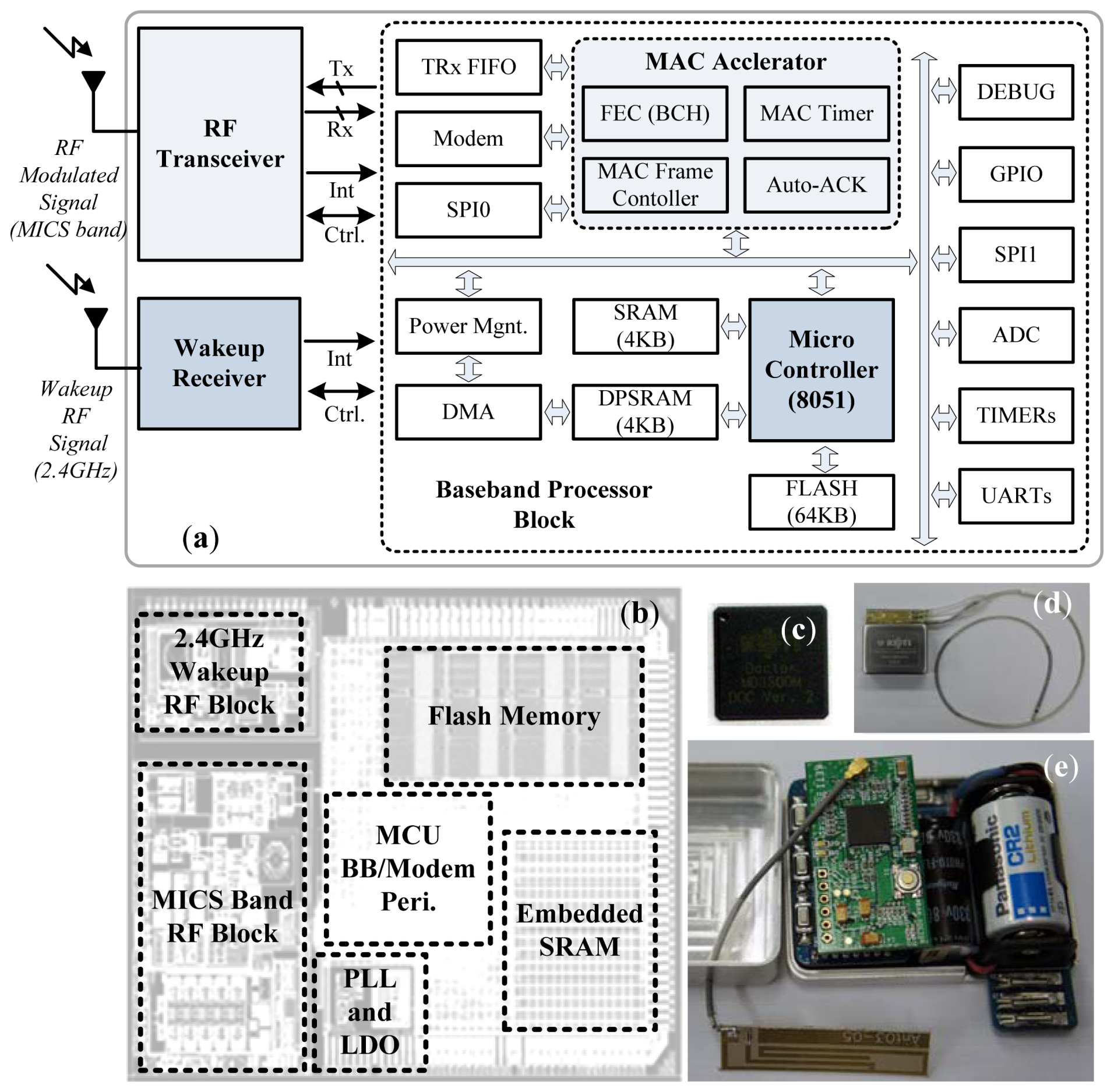
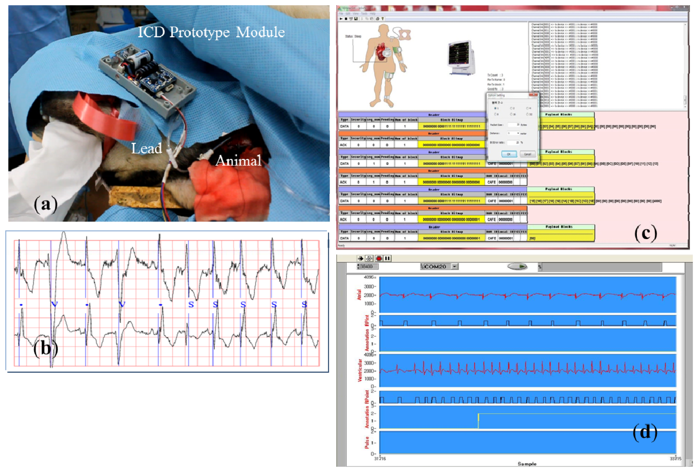
3. Implementation
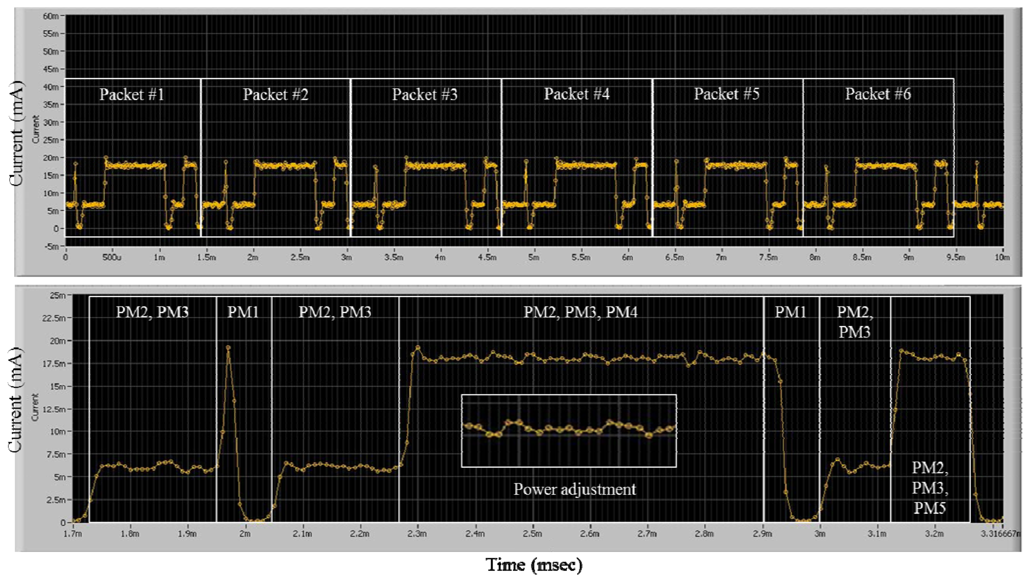
4. Experimental Results
5. Conclusions
Acknowledgments
References
- Lo, B.; Yang, G. Body Sensor Networks—Research Challenges and Opportunities. Proceedings of the IET Seminar, Antennas Propagation, Body-Centric Wireless Communication, London, UK, 24 April 2007; pp. 26–32.
- Gust, H.B.; Warren, M.S.; Margaret, A.H.; Ian, G.C.; Iain, C.M.; Luc, J.; Dominic, T.; Robert, E.P.; David, J.W.; Derek, T.C.; et al. An Entirely subcutaneous implantable cardioverter-defibrillator. N. Engl. J. Med. 2010, 363, 36–39. [Google Scholar]
- Chen, M.; Gonzalez, S.; Vasilakos, A.; Cao, H. Body area networks: A survey. Mobile Networks Appl. 2010, 16, 171–193. [Google Scholar]
- IEEE 802.15.6 TG6. Available online: http://www.ieee802.org/15/pub/TG6.html (accessed on 29 February 2012).
- Davenport, D.M.; Ross, F.J. Wearable and Implantable Body Sensor Networks for Ambulatory Patient Monitoring. The Sixth International Workshop, Berkeley, CA, USA, 10–11 August 2009; pp. 41–45.
- Bohorquez, J.D.; Chandrakasan, A. A 350W CMOS MSK Transmitter and 400W OOK Super-Regenerative Receiver for Medical Implant Communications. IEEE Symposium on VLSI Circuits, Honolulu, HI, USA, 18– 20 June 2008; pp. 32–33.
- Higgins, H. Body Implant Communication—Is it a Reality. Proceedings of Antennas and Propagation for Body-centric Wireless Communication, London, UK, 24 April 2007; pp. 33–36.
- Miller, M.J.; Vaidya, N.H. Minimizing energy consumption in sensor networks using a wakeup radio. Wireless Commun. Network. Conf. 2004, 4, 2335–2340. [Google Scholar]
- Ameen, M.A.; Ullah, N.; Kwak, K. Design and Analysis of a Mac Protocol for Wireless Body Area Network Using Wakeup-Radio. 11th IEEE International Symposium on Communications and Information Technologies (ISCIT), Hangzhou, China, 12– 14 October 2011; Volume 1. pp. 148–153.
- Shankar, V.; Schwiebert, L. Energy-efficient Protocols for Wireless Communication in Biosensor Networks. 12th IEEE International Symposium, San Diego, CA, USA, 8– 12 January 2001; Volume 1. pp. 114–118.
- Wang, X.; Vasilakos, A.V.; Chen, M.; Liu, Y.; Kwon, T.T. A survey of green mobile networks: Opportunities and challenges. Mobile Networks Appl. 2012, 17, 4–20. [Google Scholar]
- Chilamkurti, N.; Zeadally, S.; Vasilakos, A.; Sharma, V. Cross-layer support for energy efficient routing in wireless sensor networks. J. Sensors 2009, 2009, 134165. [Google Scholar] [CrossRef]
- TinyOS. Available online: www.tinyos.net/ (accessed on 20 August 2012).
- Shah, B.; James, C.; Hui, D.; Jing, D.; Jeff, R.; Anmol, S.; Brian, S.; Charles, G.; Adam, T.; Richard, H.; et al. MANTIS OS: An embedded multithreaded operating system for wireless micro sensor platforms. ACM Kluwer Mobile Networks Appl. (MONET) 2005, 10, 563–579. [Google Scholar]
- Kim, K.H.; Kopetz, H. A Real-Time Object Model RTO.k and an Experimental Investigation of Its Potentials. Proceedings of the 18th IEEE Computer Software & Applications Conference, Los Alamitos, CA, USA, 22– 24 September 1994; pp. 392–402.
- Kim, J.G.; Kim, M.H.; Heu, S. Architectures and Functions of the TMO Kernels for Ubiquitous & Embedded Real-Time Distributed Computing. Proceedings of UIC, Wuhan, China, 3–6 September 2006; pp. 71–82.
- Davis, R.; Wellings, A. Dual Priority Scheduling. Proceedings of the 16th IEEE Real-Time Systems Symposium, Pisa, Italy, 4– 7 December 1995; pp. 100–109.
- Moncusi, M.A.; Arenas, A.; Labarta, J. Improving energy saving in hard real time systems via a modified dual priority scheduling. SIGARCH Comput. Archit. 2001, 29, 19–24. [Google Scholar]
- Kim, H.; Kim, J.G. An Efficient Task Serializer for Hard Real-time TMO Systems. Proceedings of the 11th IEEE International Symposium on Object/Component/Service-Oriented Real-Time Distributed Computing, IEEE Computer Society Press, Orlando, FL, USA; 2008; pp. 405–413. [Google Scholar]
- Sukor, M.; Ariffin, S. Performance Study of Wireless Body Area Network in Medical Environment. Second Asia International Conference on, Kuala Lumpur, Malaysia, 13–15 May 2008; pp. 202–206.
- Richard, A.; Comroe, D.J.; Costello, Jr. ARQ schemes for data transmission in mobile radio systems. IEEE J. Selective Areas Commun. 1984, 2, 472–481. [Google Scholar]
- μCOSII. Available online: http://micrium.com/page/home (accessed on 10 July 2010).
- Mainwaring, A.; Polastre, J.; Szewczyk, R.; Culler, D.; Anderson, J. Wireless Sensor Networks for Habitat Monitoring. First ACM International Workshop on Wireless Sensor Networks and Applications, Atlanta, GA, USA, 28 September 2002; pp. 88–97.


| Frequency Band | 402–405 MHz |
| Channel/BW | 10 (300 kHz/Ch) |
| Modulation | DBPSK/DQPSK |
| Data Rate | 300 kbps |
| FEC | BCH |
| Pulse Shape Filter | Gaussian Filter |
| Power Consumption | Avg. 12 mA |
| Hardwired Low-MAC | Auto-CRC/FEC, Auto-ACK MAC Frame Handling |
| RF Wakeup | 2.45 GHz (OOK, Avg. 235 nA) |
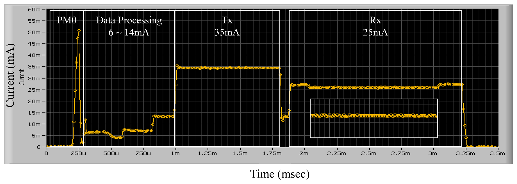
| Power Mode | Avg. Current (μA) | Description |
|---|---|---|
| PM0 | 0.235 | Sleep with radio mode |
| PM1 | 820 | Sleep with timer mode |
| PM2 | 4,023 | Waiting for an event: 32.768 kHz MCU Enables half memory one or more standby devices |
| PM3 | 9,944 | Processing data: 6 MHz MCU Enables all memory timer, ADC blocks, standby transceiver |
| PM4 | 17,402 | Transmitting frames: full-speed MCU Enables all memory, transmitter, and required IO blocks |
| PM5 | 18,532 | Receiving Frames: full-speed MCU Enables all memory, receiver requires IO blocks |
| Multi-tasking Scheduler (μCOSII) | On-time Power-aware Scheduler | ||
|---|---|---|---|
| Context Switching Time (μs) | 35 | 21 | |
| Scheduling Overhead (μs) | Worst | 189 | 170 |
| Best | 170 | 166 | |
| Average | 175 | 168 | |
| Multi-tasking Scheduler (μCOSII) | On-time Power-aware Scheduler | |
|---|---|---|
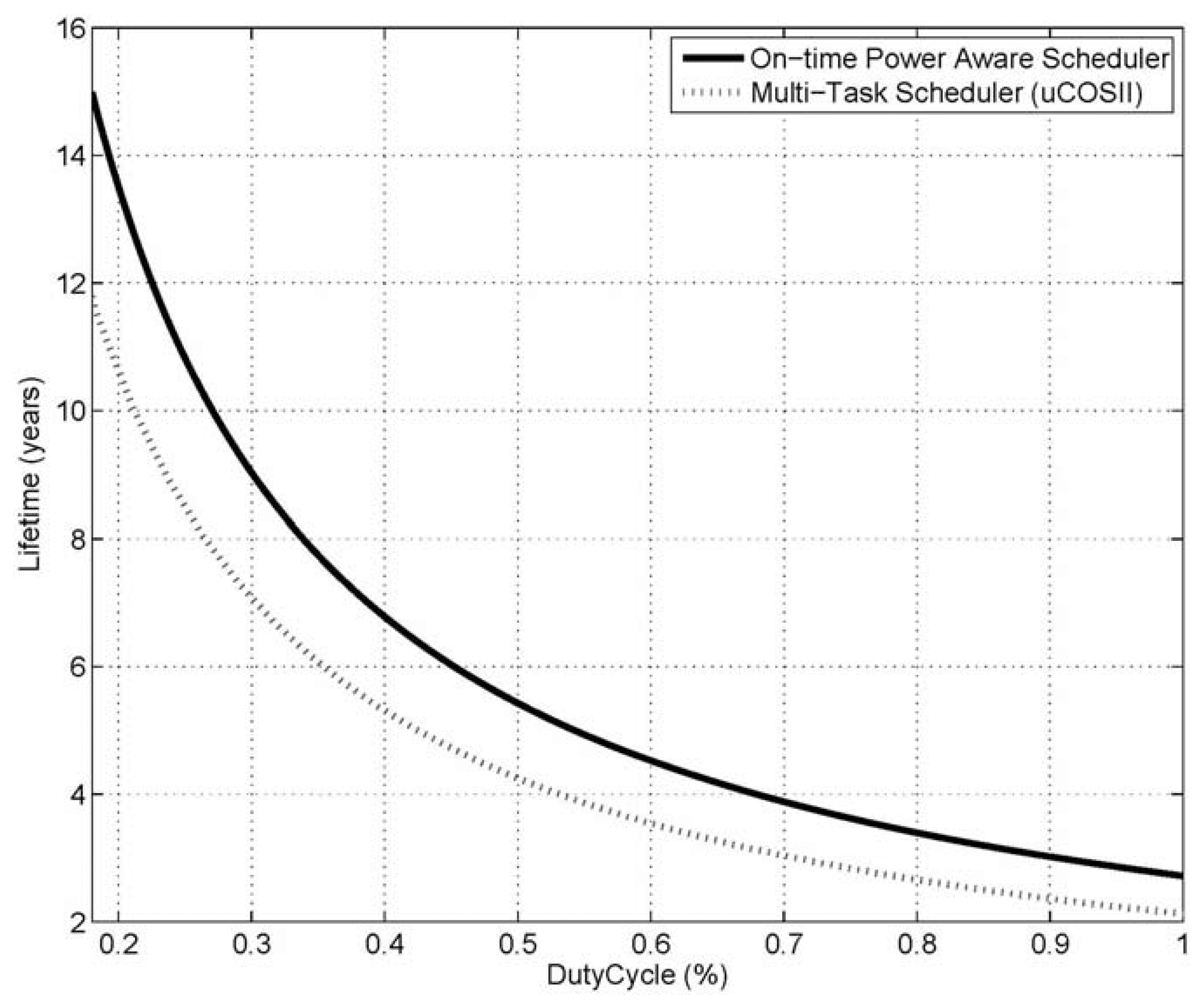
| MCU Utilization | 5.07% | 2.32% |
| Code Size in Bytes (Data/Program, μs) | 5,065/42,155 | 1,958/33,679 |
© 2013 by the authors; licensee MDPI, Basel, Switzerland. This article is an open access article distributed under the terms and conditions of the Creative Commons Attribution license (http://creativecommons.org/licenses/by/3.0/).
Share and Cite
Hwang, T.-H.; Kim, D.-S.; Kim, J.-G. An On-Time Power-Aware Scheduling Scheme for Medical Sensor SoC-Based WBAN Systems. Sensors 2013, 13, 375-392. https://doi.org/10.3390/s130100375
Hwang T-H, Kim D-S, Kim J-G. An On-Time Power-Aware Scheduling Scheme for Medical Sensor SoC-Based WBAN Systems. Sensors. 2013; 13(1):375-392. https://doi.org/10.3390/s130100375
Chicago/Turabian StyleHwang, Tae-Ho, Dong-Sun Kim, and Jung-Guk Kim. 2013. "An On-Time Power-Aware Scheduling Scheme for Medical Sensor SoC-Based WBAN Systems" Sensors 13, no. 1: 375-392. https://doi.org/10.3390/s130100375