Microelectrode Arrays with Overlapped Diffusion Layers as Electroanalytical Detectors: Theory and Basic Applications

Abstract
: This contribution contains a survey of basic literature dealing with arrays of microelectrodes with overlapping diffusion layers as prospective tools in contemporary electrochemistry. Photolithographic thin layer technology allows the fabrication of sensors of micrometric dimensions separated with a very small gap. This fact allows the diffusion layers of single microelectrodes to overlap as members of the array. Various basic types of microelectrode arrays with interacting diffusion layers are described and their analytical abilities are accented. Theoretical approaches to diffusion layer overlapping and the consequences of close constitution effects such as collection efficiency and redox cycling are discussed. Examples of basis applications in electroanalytical chemistry such as amperometric detectors in HPLC and substitutional stripping voltammetry are also given.1. Introduction
In the course of research on microelectrodes, it was shown that if a characteristic dimension of a working electrode decreases to values comparable with the electrode diffusion layer thickness this offers certain advantages for electrochemical measurements [1,2], including high density steady-state diffusion flux of electroactive species towards the microelectrode surface [3,4] and low capacity of the electrical double layer [5,6]. Current also measurable in two electrode arrangements with a small amount of supporting electrolyte [7,8] and high signal to noise ratios [9,10] make microelectrodes efficient devices for applications in trace analysis [11,12] and microanalysis [13,14]. Current responses, however, are relatively low due to the small microelectrode area [15,16] causing problems with measurement of the microelectrode response [17].
One way to overcome this main disadvantage of microelectrodes while retaining their advantageous properties is coupling them in arrays. Microelectrode systems with single microelectrodes placed at a very small distance from each other allowing for the overlap of their diffusion layers are the subject of intensive research. Close geometrical constitution is a starting point for some effects bringing significant benefits in the electroanalysis of electroactive and electroinactive species. These effects can be achieved not only by a polarization of each electrode in the array with the same potential, but also by a polarization of individually addressable microelectrodes with various potentials performed by a multipotentiostat.
Electroactive species generated on one microelectrode (the so called generator segment of the array) may diffuse across the small gap towards the second microelectrode (the collector segment of the array) where they can be electrochemically detected. Like in the case of the rotating ring disc electrode, a collection efficiency parameter can be defined. Substantially higher values can be achieved for microelectrode arrays with suitable geometry due to non-convective mass transport to the microelectrode array surface. If the original analyte is formed on the collector, it diffuses back to generator due to its concentration deficit and may oxidize/reduce again, causing a redox cycling effect that enhances current without capacity noise, thus increasing the sensitivity and selectivity of the electrochemical analysis.
2. Theory of Mass Transport at Microelectrode Arrays
Theoretical [18] studies are focused on chronoamperometry [19] and linear sweep voltammetry [20] at microelectrode arrays consisting microcylindrical and microband electrodes [21,22]. For the diffusion layer thickness δ of a microband electrode [23] the following equation can be derived:
From this equation it is apparent that diffusion layer width is growing with time and is lower than that calculated from Cottrell equation due to the edge effect [24]. For very short times the diffusion layer thickness becomes equal to that calculated from the Cottrell equation. When the time is sufficiently long, a steady-state current is reached and a voltammogram recorded at a low scan rate will have a sigmoidal shape [25]. Diffusion layer thickness grows with microelectrode width We [26]. When the microelectrode is thinner (low We), the time change of δ is higher and shorter times are needed to obtain steady-state currents [27].
2.1. Diffusion Layer Overlapping at Microband Arrays of Electrodes
For the pictorial description of the overlapping diffusion layers of an array containing microband electrodes, three cases should be distinguished:
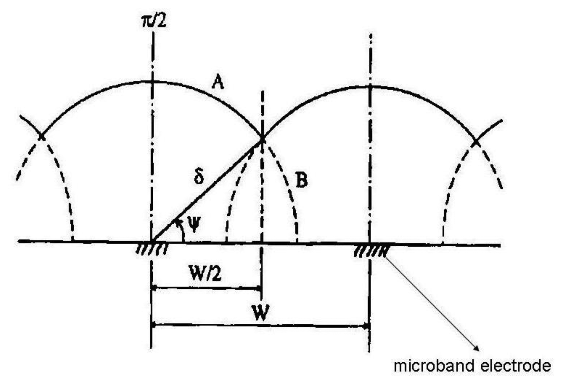
When δ < W/2 where W = We + Wg and Wg is the gap width between two adjacent microelectrodes, there is no diffusion layer overlap and the total current of the microelectrode array is equal to the sum of the currents of all microelectrodes coupled in the array:
where m is number of single electrodes in the array and current I can be calculated from Equation (2).When δ > W/2 diffusion layers of two adjacent microelectrodes are partially overlapped. Ju [28] suggested for quantitative consideration of microband electrodes overlapping angle Ψ (Figure 1):
For long electrolysis times the angle Ψ and diffusion layer thickness are growing, however the microelectrode area is lower, therefore the magnitude of the diffusion current is lower in comparison with case 1. Equation (7) offers good results in a time domain Θ < 108 in which time dependent two dimensional diffusion is taken into account and additionally the microelectrode has a sufficient length, so as to not consider the edge effect on both its ends:
where:If the angle Ψ reaches a limiting value Ψ = δ/2, diffusion layers are totally overlapped. For total current an equation has been derived:
where L is the length of one microelectrode in the array.
The quantification of diffusion layers overlap could also be described by an overlapping factor:
2.2. Chronoamperometric and Voltammetric Studies on Interdigitated Microelectrode Arrays
Generator current in dual (bipotentiostatic) mode reaches steady state in 100 ms, the time needed for species to diffuse through the gap to create a concentration gradient. Shorter times for reaching a steady state current of 10 ms can be obtained in the case where IDA microelectrodes with sub-micrometric gaps are used [32], which is important in the analysis of compounds with short lifetimes. A second advantage of IDA microelectrodes in dual mode is that chronoamperograms measured on the collector do not contain any capacity current, which represents a noise. The equation of the chronoamperometric curve was derived by Aoki [33,34] and Coen [35] based on these prerequisites:
Number of metal microbands of IDA array is sufficiently high to not count the edge effects;
The width of each metal microband We is the same;
The metal layer length L is many times greater than We;
The transport of electroactive species towards the IDA microelectrode surface ocurrs by diffusion only;
Diffusion coefficients are equal for both redox forms of analyzed electrochemical system.
The current is similar as in the case of microband electrode function of dimensionless Aoki's time Θ:
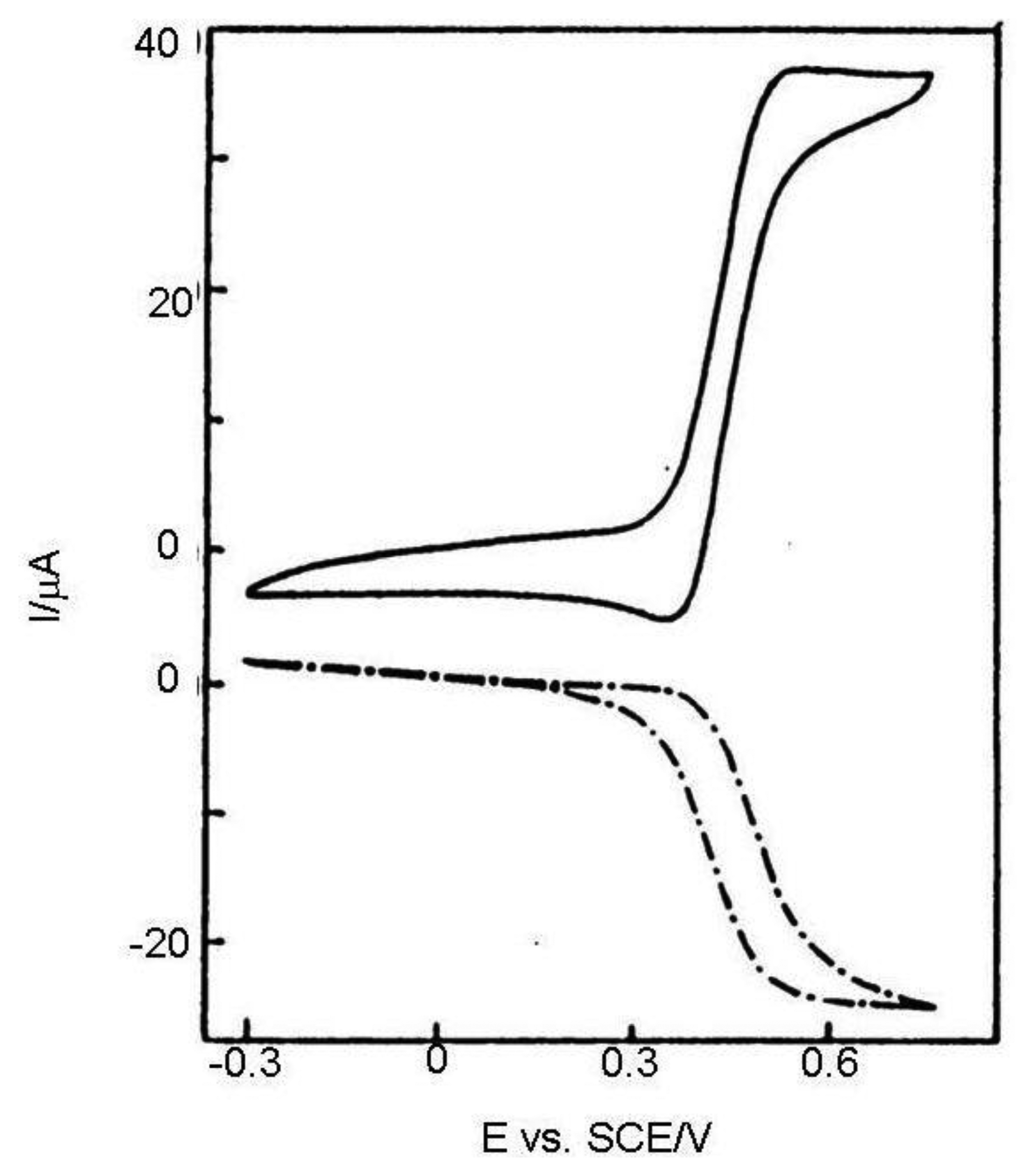
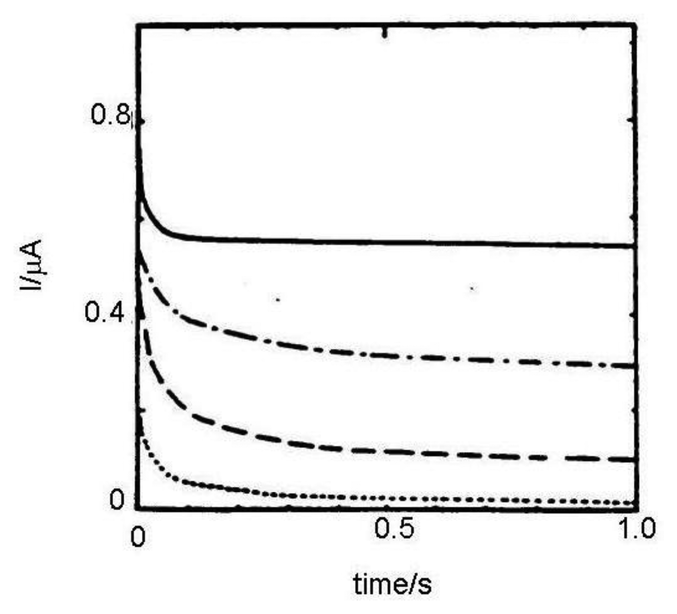
In Reference [36] results calculated from Equation (11) and Cottrell equation were compared with chronoamperograms measured in dual and single (monopotentiostatic) mode on IDA electrodes with a microband width of 3 μm and gap of 2 μm (Figure 2). Currents were divided by the number of metal microbands and normalized by the current of single microbands. It was shown that current in single mode is higher than the current calculated from the Cottrell equation, however it is lower than the current calculated from Equation (11) due to the shielding effect [34]. Current in dual mode is higher than that calculated from the Aoki-Coen equation because of redox cycling. When the gap between two adjacent metal microbands in IDA microelectrode is increased, the current in single mode will be higher because the diffusion layer overlap is decreased, but in dual mode current it is decreased due to lower redox cycling.
In a classic voltammetric experiment capacity current grows with a scan rate and is faradayic with its square root. At high scan rates the voltammetric signal becomes unclear due to the high charge current (Figure 3). It can be subtracted, but the signal is deformed by the ohmic drop. This problem may be solved by an IDA microelectrode with a short time response allowing extremely short electrolysis during cyclic voltammogram recording and investigation of fast kinetics processes.
2.3. Collection Efficiency and Redox Cycling as Consequences of Microelectrode Array Diffusion Layer Overlap
Collection efficiency is usually calculated as a collector to generator current ratio. Bard et al. [36] showed that the collection efficiency depends above all on the gap between collector and generator segment of each microelectrode array and can be expressed by the equation:
Collection efficiencies of microelectrode arrays with various geometrical arrangements were compared. On the basis of this comparison following conclusions could be summarized:
Collection efficiency depends not only on the gap between two individually addressable segments of microelectrode array, but also on the microelectrode width.
For various electrochemically reversible species with various diffusion coefficients very small changes in collection efficiency were observed, therefore collection efficiency is crucially influenced by geometrical factors.
Linear dependence of the parameter We/4 + Wg on the square root of time (chronoamperogram duration) was observed for the case when the current reaches 50% of the limiting diffusion current. The above mentioned parameter represents an average diffusion length between generator and collector and is very suitable for evaluation of the dependence of collection efficiency on geometrical factors, especially for IDA microelectrode arrays [37].
These facts are analogous to the rotating ring-disc electrode (RRDE) used in electroanalytical chemistry for detection of electroinactive species by diffusion layer titration. The analog to an inverse value of Wg is the angle rate ω. Current response of RRDE is enhanced by an analyte convection during hydrodynamically stable conditions. Collection efficiency on the ring is usually less than 50% and is substantially lower than for vertically separated IDA microelectrode arrays reaching at least 95% or higher. An additional disadvantage of RRDE vs. IDA is the high noise related to brush contacts. Another substantial difference between RRDE and IDA is the interrelationship of diffusion layers. In the case of RRDE only the diffusion layer of the ring is influenced by the disc electrode reaction due to the centrifugal movement of analyte in close vicinity to the rotating body of the electrode, therefore the ring will never serve as a generator [38–40].
The second interesting feature of microelectrodes with interacting diffusion layers is redox cycling [41]. This phenomenon occurs when one microelectrode (the generator) is electroactive and an electrochemically reversible redox species is generated. After diffusion across the gap it is amperometrically detected on the second microelectrode with a potential corresponding to the opposite electrode reaction to the generator one (dual mode). Generator and collector currents are both in steady state and the generator current is several times higher as in the case when the collector microelectrode is disconnected from the potentiostat (single mode). This is also called forced redox cycling. An unpotentiostated microelectrode in close vicinity to the generator does not influence its response and behaves as an insulator. When a linear sweep voltammogram is recorded at very slow scan rates (less than 5 mV·s−1) a quasi-steady state wave is obtained, however its height is several times lower in comparison to when a suitably polarized collector microelectrode is used.
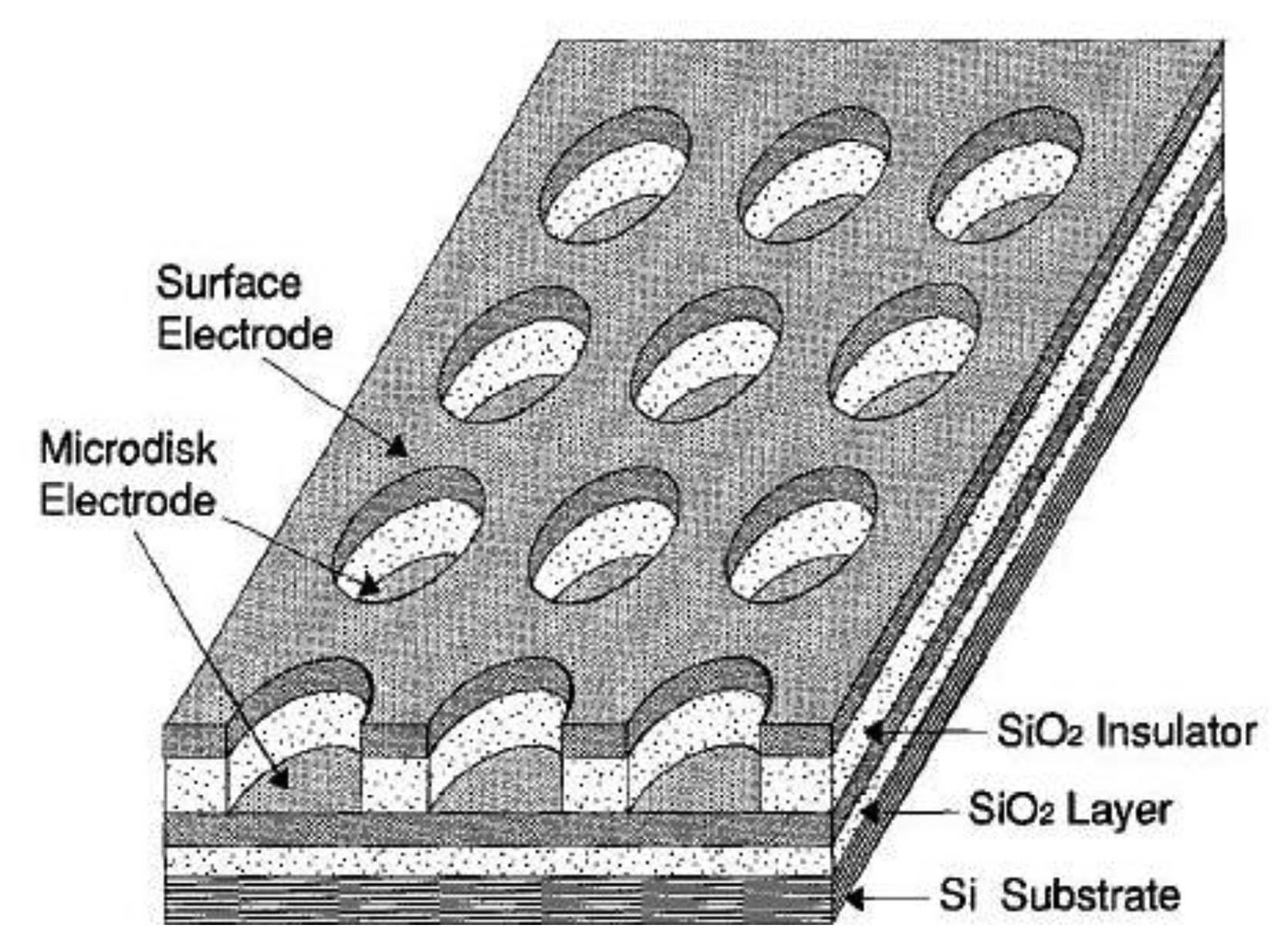
If a macroelectrode with significantly greater area is placed into the diffusion layer of a microelectrode which generates an electrochemically reversible species a self-induced redox cycling occurs. The macroelectrode current is high, however the diffusion layer of the microelectrode reaches only a small portion of the macroelectrode, therefore its current change is small and problematically measurable. Microelectrode current is substantially enhanced due to redox cycling between a polarized microelectrode and a polarized macroelectrode. Surprising results were obtained on the microelectrode while the macroelectrode was disconnected from the bipotentiostat. Current on the microelectrode is practically the same as measured with a polarized macroelectrode. The mechanism of self-induced redox cycling was explained by Horiuchi using a combined twin chip with microdisc array electrode (Figure 4) and a macroelectrode with the same area [42].
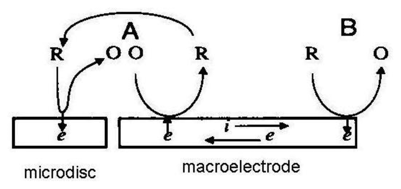
The current on the microdisc array electrode is higher than on the same microelectrode placed on a chip without macroelectrode. The oxidized form produced on the microdisc electrode diffuses to the vicinity of the macroelectrode and creates a local concentration gradient (point A in Figure 5). When equilibrium is established on the macroelectrode surface the opposite reaction is induced and at point B the same electrode reaction ocurrs as on the microdisc electrode. The reduced species generated on the macroelectrode at point A diffuses back to the microdisc electrode due to its concentration deficit at this location and oxidizes again, thus closing the redox cycle. Current enhancement grows with the area of the macroelectrode until it is hundred times greater than the area of the microelectrode.
A parameter for quantitative consideration of redox cycling is the number of redox cycles. It is calculated from the collection efficiencies. If collection efficiency in the direction from generator to the collector is Φ1 and in the opposite direction from collector to the generator it is equal to Φ2, the number of molecules of a species obeying one electron electrode reaction diffusion on the collector is equal to NΦ1 and number of molecules diffusing back to the generator is therefore NΦ1Φ2 and the number of molecules diffusing to the bulk phase of the solution is then equal to N − NΦ1Φ2 where N is number of molecules oxidized per time unit on the generator. Based on these ideas the number of redox cycles can be expressed as:
Accuracy of parameter the RC depends on the accuracies of determination of the collection efficiencies in both directions, however in the most of studies the generator and collector were the same. The average number of redox cycles can also be calculated as the current ratio of a generator in dual mode Ig and in single mode I0. The parameter Ig/I0 is highly reproducible and may substitute for RC values calculated from Equation (13) in the collection efficiencies range of 10%−99%.
3. Fabrication of Microelectrode Arrays with Interacting Diffusion Layers
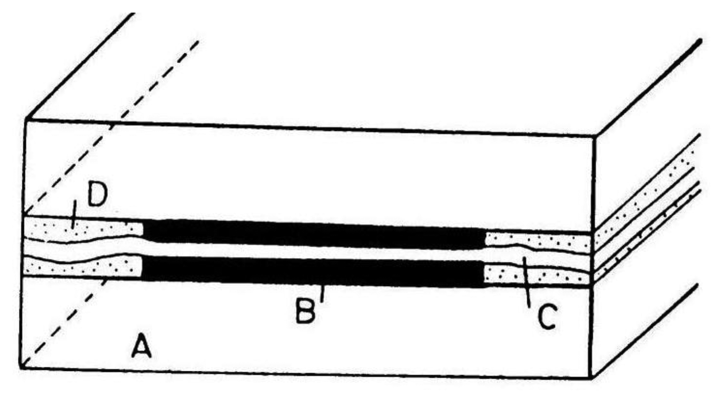
Microband electrodes (Figure 6) are the simplest type of microelectrode arrays with interacting diffusion layers. They are fabricated by placing insulating foil of width 2, 4 or 6 μm between Pt foil with width of 4 μm on a glass wafer [43]. The construction was improved by adding a small amount of epoxide on the glass wafer and between all foils. The electrode surface was cleaned by sonication in a mixture of methanol and water. The electrode length was determined optically.
Ferocene in acetonitrile solution served as a testing redox system. Collection efficiency calculated as collector vs. generator current ratio was in the range of 10% to 50% and its value does not depend on ionic strength of the solution [44–46].
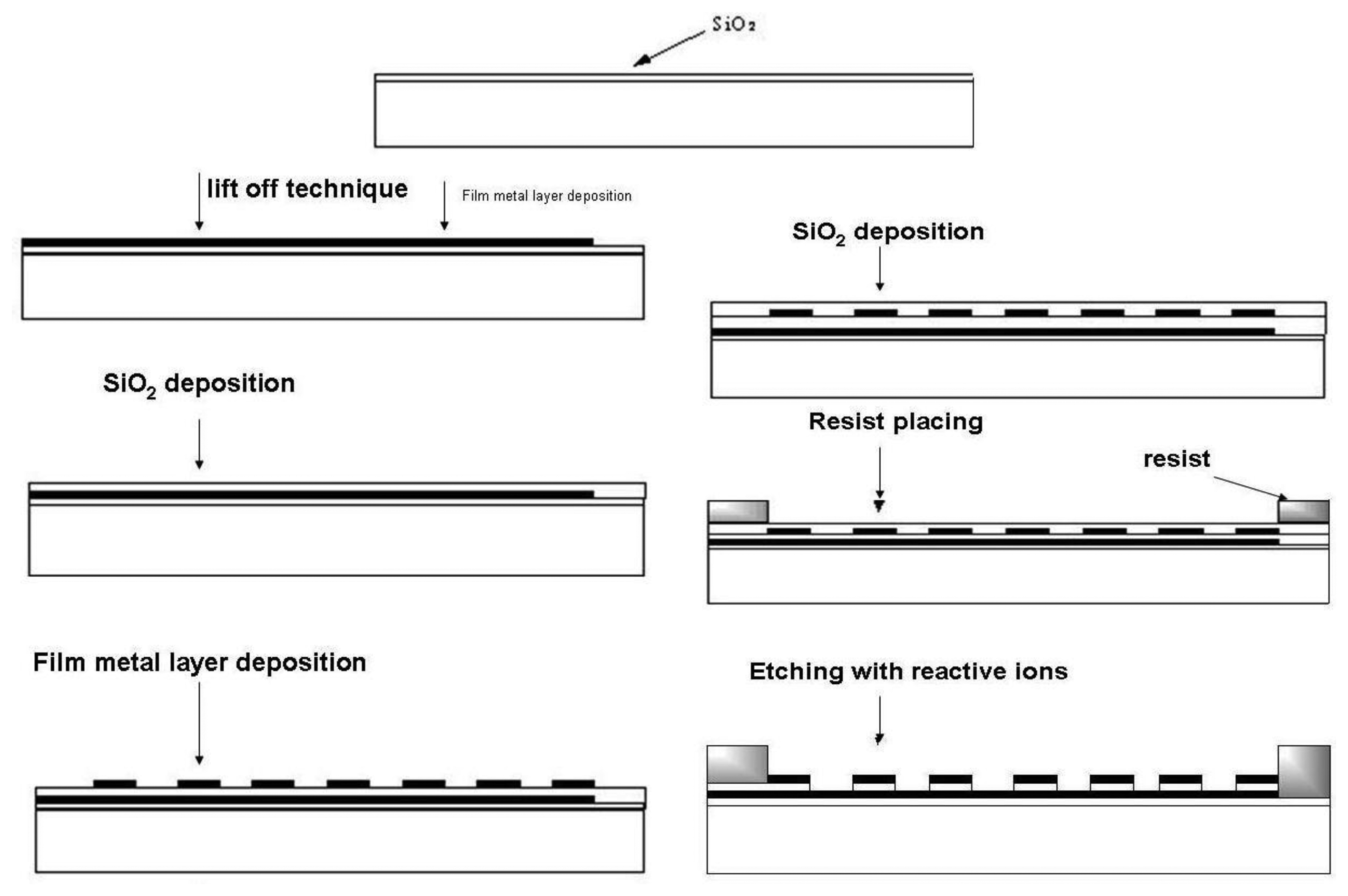
A very efficient fabrication technique for microelectrode arrays is photolithography, widely used in book printing, gravure printing, offset techniques and microelectronics. The most important field of photolithography is planar technology for the fabrication of planar microelectronic elements like integrated circuits, etc. In this technique a silicon wafer covered with a thin layer of silicon dioxide is used. A continuous metal layer is placed on this wafer and final shaping is performed by photolithographic etching. By using photoresists a horizontal relief is formed in dielectric and metal layers on the surface of silicon semiconductor. Electron resists are mostly used for microelectrode array fabrication because relief etching is performed by a flux of electrons, X–rays and reactive ions. Photoresist exposition is a diffusion process based on insolubility of cross-linked (illuminated) polymers. During photoresist exposition the dark part of the photoresist is dissolved in hot solution of the developer, leaving uncovered parts of SiO2 on the wafer surface and the illuminated (cross-linked) part of the photoresist will remain. Uncovered parts are etched by using a photomask for obtaining the desired geometrical shape. Finally, a metal layer is incorporated into the etched places [47–49]. For microelectrode array fabrication process chemically cross-linked photoresists are successfully used [50–53]. Their work is based on diffusion of acid protons catalyzing cross-linking process into the resist. After exposition protons are reduced to H2 and lose catalytic ability [54].
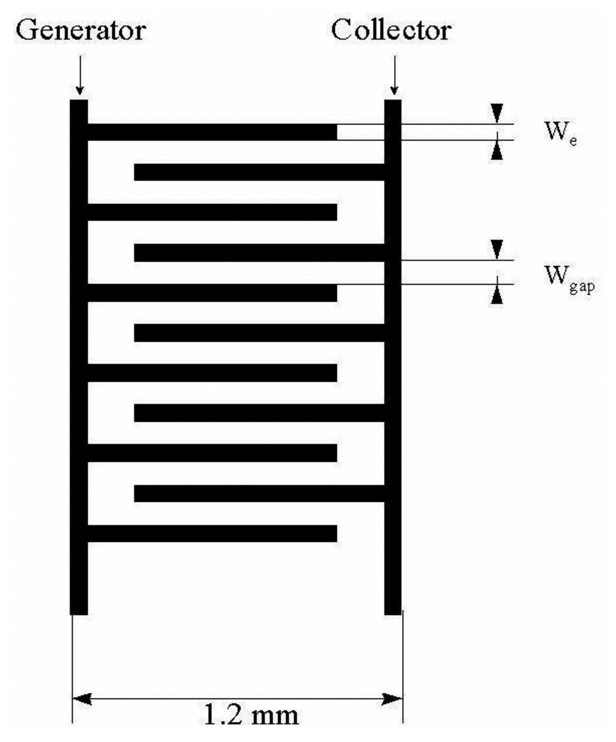
Horizontally (Figure 7) and vertically (Figure 8) separated IDA microelectrodes were fabricated photolitographically. On a thermally oxidized silicon wafer a layer of photoresist was placed and exposed by UV rays through the photomask, then rinsed with deionized water, followed by Pt film placement with a width of 100 nm. Silicon dioxide film was etched with reactive ions in tetrafluoromethane [32,41]. During characterization a five times greater signal on a vertically separated IDA array with a submicrometrical gap of 0.5 μm (RC = 35) was obtained in comparison with a planar IDA microelectrode (RC = 7) with a gap of 2.5 μm corresponding to a high level of redox cycling [41].
It was also shown that carbon [56–58] may serve as an electrode material for IDA microelectrode fabrication. In [58] vertically separated IDA microelectrodes with a double layer of carbon and platinum are described. Fabrication of carbon film is based on pyrolysis of 3,4,9,10 perylene-tetracarboxylic acid dianhydride (PTCDA). For obtaining carbon films with large area and smooth surface slow evaporation of PTCDA is needed. The temperature of pyrolysis is about 1,000 °C to ensure good carbon film conductivity. The structure of the carbon film was checked by X-ray diffraction and Raman spectrometry. Cyclic voltammogram shows a relatively high potential shift corresponding to a high IR drop. It may be decreased by using IDA microelectrodes with combined microelectrode segments (one carbon and a second of platinum). High background current is caused by a high roughness of carbon film surface (average thickness of 5 nm).
4. Basic Electroanalytical Applications of Microelectrode Arrays with Interacting Diffusion Layers
Microelectrode arrays with interacting diffusion layers are very useful potential tools in contemporary electroanalytical chemistry. They can be used as sensors for fast, sensitive and highly selective determination of species which are important in biology, food, medicine and the environment. Electroanalytical voltammetric techniques based on using microelectrode arrays with interacting diffusion layers utilize effects caused by a close geometrical arrangement of individually addressable segments in the array. Redox cycling on the adjacent segments is able to enhance the current response, which may increase the sensitivity. The selectivity is enhanced by the fact that electrochemically irreversible redox pairs are not transferred on the collector [59]. Certain limitations concern usability only in the case of reversible or quasireversible charge transfer of the target species as well as the fact that a chip with a microelectrode array must be placed in non-aggressive media to avoid its damage. The safe pH range is shown to be from 3 to 11 [60]. One way to overcome these limitations is surface modification of microelectrode arrays with various polymeric films [61–63].
4.1. Detection of Catecholamines with IDA Microelectrodes
Short time response and current without capacity noise is utilized for amperometric detection of species in a flow system [64]. Amperometric detection in liquid chromatography is very popular in the analysis of trace amounts of organic species due its high sensitivity, selectivity [65], in addition if a microelectrode is used as amperometric detector only small amounts of the supporting electrolyte are involved. In the eighties and nineties of the last century a series of individually polarizable electrodes started to be used for this type of analysis [66–68]. However, there was no diffusion layer overlapping due to the large distance between each other, therefore they were substituted by microelectrodes with close geometrical arrangement of individually addressable segments [69,70]. The simplest type of this kind of microelectrode arrays was the double rectangular electrode (DRE) [71]. DRE has the ability to enhance the selectivity of detection when on one rectangle the interferents are irreversibly oxidized and the chromatogram obtained on the second rectangle with a more negative potential as the first one does not contain peaks of irreversible interferents. This situation is also practically the same for IDA microelectrodes [72–74], however its geometry allows one to reach substantially higher values of collection efficiency as well as higher level of redox cycling, thus enhancing current response [75–79]. This methodology is applied to the selective detection of catecholamines [80–87]. Catecholamines are important biological compounds mediating a nerve perturbation in a synaptic cleft, therefore their sensitive and selective detection is needed. Biological samples contain a significant amount of interferents [88,89] such as L-ascorbic acid (AA), uric acid (UA) and catecholamine metabolites like dihydroxyphenylacetic acid (DOPAC) and homovanilic acid (HVA) so it is important to eliminate the influence of these interferents on the sensitivity and selectivity of catecholamine determination. Collection efficiencies for catecholamines are equal to 0.53–0.56 and collection efficiencies of interferents are practically zero due to their electrochemical irreversibility. Consequently, peaks of catecholamines will become dominant in a chromatogram recorded at the collector. It was observed that steady state current on IDA microelectrode in dual mode depends on the cubic root of the flow rate. This fact is caused by redox cycling [90–92]. When an IDA microelectrode with a gap around of 1 μm is used its response is not dependent on flow rate. Further improvement of the detection limit of the determination of catecholamines results from the use of carbon IDA microelectrode arrays [93–99]. Before measurement a carbon IDA microelectrode must be electrochemically pretreated to assure a reversible response to catecholamines [100–103], however capacity current is increased and the potential window will become narrower after pretreatment [104,105]. If a carbon IDA electrode with some hundreds of generator–collector pair segments is used collection efficiency for catecholamines may increase to 70%. Due to the high level of redox cycling and hence high signal to noise ratio a detection limit around 10−11 mol·dm−3 may be reached. This corresponds to 5 fg resp. 32 amol of dopamine (absolute amount) [106,107].
IDA microelectrodes avoid the disadvantages of classical electrochemical detection such as reactions of several species on the electrode [108] and high background current. Electrochemical detection is faster than fluorescence detection based on the derivatization with 1,2-diphenylenediamine (DPE) which involves long reaction times [109–111] and other operations [112] as well as chemiluminiscence detection [113–115].
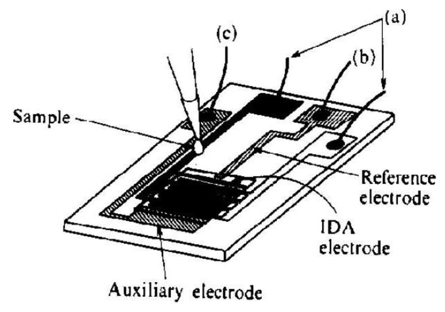
Another approach in the improvement of the selectivity of catecholamines determination is the use of electrochemical cells with a small volume. Microcells are constructed by lithographic placement of the sensor with 50 pairs of the segment with a width of 3 μm and 2 or 5 μm gap distance onto a silicon wafer together with reference and counter microelectrodes (Figure 9) [116]. Ascorbic acid was used as interferent. The selectivity of the sensor was tested on a 4 mL macrocell and 2 μL microcell. The model sample contained dopamine with a concentration of 1 × 10⁻⁴ mol·dm−3 and ascorbic acid at a concentration of 1 × 10⁻³ mol·dm−3.
Results were compared with a dopamine signal without interferent (Figure 10). Anodic current in a macrocell with an addition of ascorbic acid is very high, corresponding its irreversible oxidation. Anodic current in a microvolume cell is also high, however in a certain time it reaches the current value of the sample without ascorbic acid due to its bulk phase (coulometric) oxidation because sensor and sample volume have comparable dimensions.
Lowering the analyzed volume increases the selectivity of electrochemical detection of catecholamines. Collection efficiency of dopamine on the concentration of ascorbic acid was investigated. It was shown in the case of macrocell decreasing collection efficiency occurred when the concentration of ascorbic acid is increased. However collection efficiency in a microvolume cell remains stable around more than 50%, even when the concentration of ascorbic acid is 30 times higher than the concentration of dopamine [116,117].
4.2. Electrochemical Stripping Voltammetry of Reversible Redox Species with Self Induced Redox Cycling
The lowest detection limit of all electroanalytical techniques corresponds to electrochemical stripping analysis [118–120]. It is widely used for determination of metal ions and halides in water, food, biological fluids and environmental samples [121–123]. The detection limit of electrochemical stripping analysis is usually found in order of 10−1–10−11 mol·dm−3 [124–126]. However this technique can only be applied to certain species such as metal ions, halides or adsorptive organic compounds by using special techniques such as chemical modification of the working electrode surface or adsorptive complex formation [127–131]. Substitutional stripping voltammetry by using an interdigitated microelectrode array as working electrode extends the usability of stripping analysis to species for which deposition onto an electrode surface is not possible due to various reasons. The common reason is the solubility of both forms of the target redox analyte.
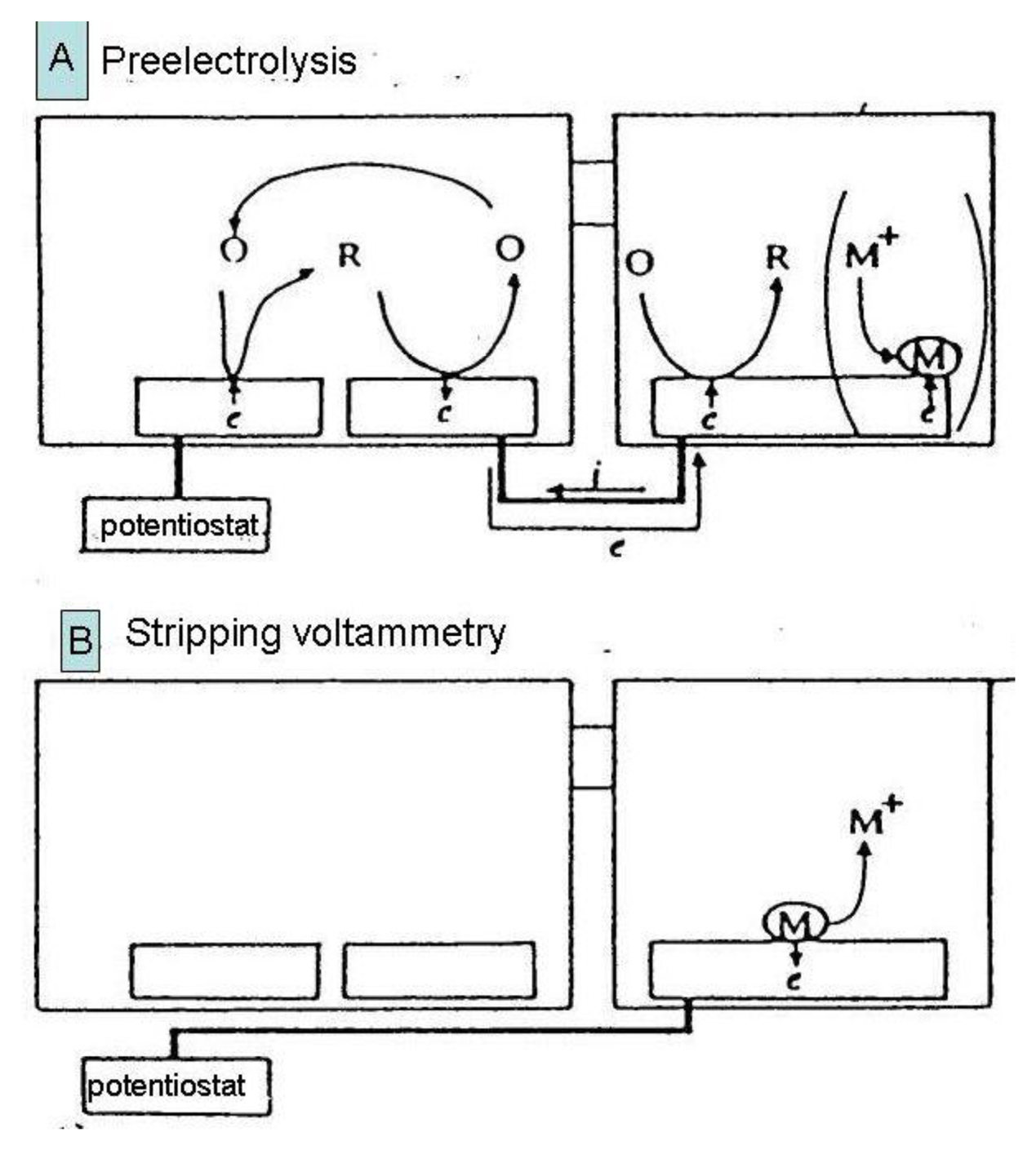
Substitutional stripping voltammetry (SSV) also allows detection of reversible species where both forms of the redox system are very soluble. Self-induced redox cycling as described when explaining the interaction of diffusion layers of two closely spaced electrodes may also be realized in a double compartment cell (Figure 11) [132].
In this experimental arrangement a pair of individually addressable microelectrode segments forming an IDA microelectrode is placed in the first compartment and a macroelectrode in the second one. One of pair of microelectrodes is connected with the macroelectrode. In this system a charge produced by self-induced redox cycling in the first compartment is transferred into another electrochemical reaction in the second compartment.
In the case depicted in Figure 11, an oxidized form of a reversible redox system is analyzed. Redox cycling in the first (left) compartment may induce in the second (right) compartment deposition of a substitutional compound as a solid species onto the macroelectrode surface [132,133]. This process is called preelectrolysis and its duration depends on the operator. The amount of substitutional species is determined by its stripping like in a classic voltammetric stripping analysis (Figure 12). It is proportional to the concentration of the oxidized form of the target species in the first compartment and a stripping peak is then suitable for its quantification. The term substitutional stripping voltammetry is derived from a fact that during preelectrolysis a substitutional species is deposited in the second compartment of the measuring system and stripped instead of analyzed as a reversible species with both redox forms being soluble in the solvent [133].
Substitutional stripping voltammetry has two variants. The first one is cathodic SSV in which the analyzed species is ferrocenylmethyltrimethylammonium bromide (aq–ferrocene) [133]. As a substitutional electrolyte iodide was used, together with a silver electrode in the second compartment. During preelectrolysis AgI is deposited onto the silver electrode surface offering a stripping peak at the potential of −0.2 V vs. SCE. Potential of the left electrode was fixed at 0.55 V vs. SCE corresponding to the limiting current of the oxidation to aq-ferricene. The silver electrode was polarized by a scan in the range of 0.25 to −0.4 V vs. SCE during the stripping step.
If the concentration of iodide is equal to 1 × 10⁻⁶ mol·dm−3 the stripping peak height is proportional to the preelectrolysis time and no stripping peak was observed in the absence aq-ferrocene. However by comparison of the charge passed during redox cycling with the stripping charge of AgI it was observed that the coulombic efficiency of charge transfer between two compartments is only 3.2%. This value is too low for assuring high sensitivity. By enhancing the iodide concentration to 1 × 10⁻⁵ mol·dm−3 practically 100% coulombic efficiency was achieved, however small stripping peaks of AgI was observed even when no aq-ferrocene is present in the first compartment because at this higher concentration of iodide deposition in the second compartment is induced by the residual current at a potential of 0.55 V vs. SCE in the first compartment. Approximately a 500 times greater signal is obtained compared to cyclic voltammetry.
Anodic SSV is based on the redox cycling of hexaamminruthenium(III) chloride [133]. It is the oxidized form of typically reversible redox system with a reduction potential of −0.2 V vs. SCE, therefore current flows in an opposite direction than in the case of aq-ferrocene. When this species is reduced on one segment of an IDA array on the second segment it is oxidized and silver ions are deposited on a glassy carbon electrode [134]. Then the silver is anodically stripped in a positive sweep of the potential.
Figure 11 depicts the experimental arrangement for anodic SSV. It happens by using a switch in a position A polarize the left segment of the IDA array working microelectrode with a constant potential of −0.4 V vs. SCE. At this potential reduction of [Ru(NH3)6]3+ to [Ru(NH3)6]2+ proceeds with limiting current. The right segment of the IDA array is connected with a glassy carbon electrode in the second compartment of the electrolytic cell. During preelectrolysis redox cycling of [Ru(NH3)6]3+ is transferred to the deposition of AgI on glassy carbon electrode in a stirred solution. After the preelectrolysis time (typically 10 min) the switch is turned to position B and the solution is stabilized during quiet conditions for 10 s. Then the potential of glassy carbon electrode is scanned from −0.4 to +0.5 V vs. SCE with a scan rate of 20 mV·s−1. The stripping peak of silver was found at +0.35 V vs. SCE. No peak was observed at the potential lower than −0.4 V or when no [Ru(NH3)6]3+ was present in a solution in the first compartment [132]. The cyclic voltammogram on the left segment of the IDA array was measured and compared with an oxidation current on the right segment of the IDA. No significant difference was observed, indicating a high collection efficiency, but oxidation current contained a substantially smaller amount of interference signals. This fundamental decrease of the background signal is the basis for preelectrolysis to assure a high signal to noise ratio achieving such high sensitivity also for the stripping peak. By comparison between cyclic voltammograms with redox cycling and silver stripping peak approximately 80 times greater signal was obtained, however this signal is 2,500 time higher than one obtained by simple cyclic voltammetry.
Otherwise, coulombic efficiency of transfer oxidation of [Ru(NH3)6]3+ to silver stripping was only around 43%. Detection limit was estimated to 1 × 10⁻⁸ mol·dm−3 and linear dynamic concentration range was from 1 × 10⁻⁸ to 1 × 10⁻⁷ mol·dm−3. Linearity was disappeared when the concentration of [Ru(NH3)6]3+ was increased to 1 × 10⁻⁶ mol·dm−3 [132] due to the decreasing coulombic efficiency.
As macroelectrode material for the deposition of silver ions a glassy carbon electrode was used. GC electrodee have a wide potential window and charge transfer between silver ions and its surface is reversible. Another electrodes, e.g., the hanging mercury electrode are also suitable for use in SSV experiments, however the potential window is narrower, especially in an anodic potential range thus limiting stripping potential sweeping. For assuring the sufficient deposition rate needed for charge consumption generated by redox cycling silver ions are suitable, while Hg2+ ions are also suitable because their potential is sufficiently higher, like the potential of [Ru(NH3)6]3+ oxidation. Some limitations may occur if various anions forming complexes with Hg2+ are present in a solution [134]. Further important parameters to be optimized are: macroelectrode area, concentration of substitutional species and scan rate during the stripping step. When the concentration of analyzed species is low, the signal to noise ratio is also low and a very small amount of Ag+ ions is deposited on the macroelectrode. In addition the faradayic and capacity current of various impurities remain stable therefore it is difficult to obtain a baseline on a big macroelectrode. It seems to be optimal when a glassy carbon electrode with a diameter of 1 mm is used as macroelectrode for the deposition of substitutional species. Concentration of Ag+ is also an important factor for decreasing the SSV detection limit. When the concentration of Ag+ is lower or the same as the concentration of the analyzed species in the first compartment coulombic efficiency is substantially lower than 100%, because deposition of silver ion will become the rate determining step and the whole charge produced by redox cycling during preelectrolysis cannot be transferred to the Ag+ deposition. Coulombic efficiency is near 100% when the Ag+ concentration is at least one order greater than the concentration of [Ru(NH3)6]3+. Similar results were obtained for cathodic SSV with iodide as substitutional species and aq-ferrocene as analyte. Scan rate during the stripping step is also an important parameter for the reliability of SSV determinations. High scan rates produce high stripping peaks with a biased baseline and it is difficult to dissolve all the silver with a linear sweep of the potential [135]. Otherwise low scan rates cause underpotential deposition of silver [136]. For both limitations a satisfactory value is 20 mV·s−1. Starting potential for stripping is usually set up to the potential of the generator (left) segment of the IDA array. Higher potential is also possible, however in this case current caused by switch turning from preelectrolysis mode to stripping mode may affect the stripping peak. This current does not occur if the potential of the generator segment of the IDA array and the starting potential of the stripping sweep are equal.
When SSV voltammograms of 1 × 10⁻¹¹ mol·dm−3 [Ru(NH3)6]3+ for various preelectrolysis times were measured, stripping peaks of silver were observed at a potential of 0.3 V vs. SCE and they are dependent on preelectrolysis time and no peaks are obtained in the absence of [Ru(NH3)6]3+. This shows that electrolysis of [Ru(NH3)6]3+ causes the deposition of silver ions [133].
Peak height after 20 min preelectrolysis was around 0.5 nA. The theoretical value of the limiting current of the [Ru(NH3)6]3+ solution with a concentration of 1 × 10⁻¹¹ mol·dm−3 in dual mode for the IDA microelectrode was 0.8 pA [133]. SSV signal is 630 times higher. Peak area was 1.1 nC. Charge passed during preelectrolysis was 0.96 nC, therefore coulombic efficiency is 115%. This 15% deviation may be caused by dissolved oxygen. Oxygen was removed before preelectrolysis by bubbling with pure nitrogen, however it is impossible to bubble the solution during preelectrolysis because redox cycling is very sensitive to convection. A small amount of oxygen is able to dissolve in a solution during the 20 min of preelectrolysis.
Concluding, SSV is a suitable electroanalytical technique for the detection of reversible redox species at very low concentrations. The current from the collector segment of IDA array can be integrated because it has a small background signal content. The integration may be performed by coulometer, however its resistivity may interfere with redox cycling. In SSV experiments direct connection of electrodes in various compartments minimizing internal resistivity and macroelectrode behaves as an ideal chemical coulometer.
SSV was successfully applied to the detection of dopamine. If an IDA microelectrode is used in dual mode a detection limit of 1 × 10⁻⁸ mol·dm−3 was obtained. In SSV experiments a silver macroelectrode and iodide were used for substitutional stripping. After optimization of measurement conditions a cathodic stripping peak dependent on preelectrolysis time and concentration of dopamine was observed. It was shown that it is possible to detect dopamine on a concentration level of 1 × 10⁻⁹ mol·dm−3. This detection limit is lower than on an IDA electrode in dual mode, but substantially higher than for the detection of [Ru(NH3)6]3+ because the detection limit of AgI stripping is about 1–2 orders of magnitude higher than anodic stripping of silver. One possibility to increase sensitivity of substitutional stripping of dopamine is by applying gold IDA microelectrodes or carbon IDA microelectrodes with quasi-reversible charge transfer of dopamine [137].
5. Conclusions
In this contribution microelectrode arrays with overlapped diffusion layers are described, highlighting the theory of charge transfer, discussion of close constitution effects and basic applications. These powerful electroanalytical tools can be used as very sensitive and selective detectors hyphenated with separation analytical techniques. They may recognize signals of irreversible redox systems from reversible redox species due to redox cycling in dual mode at two adjacent microelectrodes polarized with various potentials corresponding to direct and opposite electrochemical reactions taking place in electrochemical systems. Microelectrode arrays may be also used for stripping analysis of species which cannot be deposited onto an electrode surface as solid species because of their natural solubility in a solvent. Redox cycling is possible to transfer current to another compartment of an electrolytical cell inducing substitutional species deposition processes.
Acknowledgments
Financial support from Scientific Grant Agency of Slovak Republic (project VEGA 1/0008/12) and Grant Agency of Faculty of Education (project GAPF 1/21/2013) is gratefully acknowledged.
Conflict of Interest
The author declares no conflict of interest.
References
- Wightman, R.M. Voltammetry with microscopic electrodes in new domains. Science 1988, 40, 415–420. [Google Scholar]
- Suzuki, I.; Fukuda, M.; Shirakawa, K.; Jiko, H.; Gotoh, M. Carbon nanotube multi-electrode array chips for noninvasive real-time measurement of dopamine, action potentials, and postsynaptic potentials. Biosens. Bioelectron. 2013, 49, 270–275. [Google Scholar]
- Potter, K.A.; Buck, A.C.; Self, W.K.; Callanan, M.E.; Sunil, S.; Capadona, J.R. The effect of resveratrol on neurodegeneration and blood brain barrier stability surrounding intracortical microelectrodes. Biomaterials 2013, 34, 7001–7015. [Google Scholar]
- Kilchenmann, S.C.; Rollo, E.; Bianchi, E.; Guiducci, C. Metal-coated silicon micropillars for freestanding 3D-electrode arrays in microchannels. Sens. Actuators B Chem. 2013, 185, 713–719. [Google Scholar]
- Davis, F.; Higson, S.P.J. Arrays of microelectrodes: Technologies for environmental investigations. Environ. Sci. Processes Impacts 2013, 172, 1–12. [Google Scholar]
- Trouillon, R.; Lin, Y.Q.; Mellander, L.J.; Keighron, J.D.; Ewing, A.G. Evaluating the diffusion coefficient of dopamine at the cell surface during amperometric detection: Disk vs. ring microelectrodes. Anal. Chem. 2013, 85, 6421–6428. [Google Scholar]
- Dawson, K.; Baudequin, M.; Sassiat, N.; Quinn, A.J.; O'Riordan, A. Electroanalysis at discrete arrays of gold nanowire electrodes. Electrochim. Acta 2013, 101, 169–176. [Google Scholar]
- Oliveira, T.M.B.F.; Becker, H.; Longhinotti, E.; de Souza, D.; de Lima-Neto, P.; Correia, A.N. Carbon-fibre microelectrodes coupled with square-wave voltammetry for the direct analysis of dimethomorph fungicide in natural waters. Microchem. J. 2013, 109, 84–92. [Google Scholar]
- Tsigara, A.; Benkhial, A.; Warren, S.; Akkari, F.; Wright, J.; Frehill, F.; Dempsey, E. Metal microelectrode nanostructuring using nanosphere lithography and photolithography with optimization of the fabrication process. Thin Solid Films 2013, 537, 269–274. [Google Scholar]
- Tomčík, P.; Bustin, D. Voltammetric determination of iodide by use of an interdigitated microelectrode array. Fresenius J. Anal. Chem. 2001, 371, 562–564. [Google Scholar]
- Battistel, D.; Daniele, S. Determination of trace bismuth by under-potential deposition-stripping voltammetry at mesoporous platinum microelectrodes: Application to pharmaceutical products. J. Solid State Electrochem. 2013, 17, 1509–1516. [Google Scholar]
- Santhiago, M.; Wydallis, J.B.; Kubota, L.T.; Henry, C.S. Construction and electrochemical characterization of microelectrodes for improved sensitivity in paper-based analytical devices. Anal. Chem. 2013, 85, 5233–5239. [Google Scholar]
- Kafka, J.; Skaarup, S.; Geschke, O.; Larsen, N.B. Micro-drilling of polymer tubular ultramicroelectrode-arrays for electrochemical sensors. Sensors 2013, 13, 6319–6333. [Google Scholar]
- He, J.C.; Ma, X.L.; Zhu, Y.H.; Li, F.W.; Tang, X.F.; Zhang, X.G.; Zhang, M.N. Facile fabrication of regular Au microband electrode arrays for voltammetric detection down to submicromolar level by hydrogel etching. Electrochem. Commun. 2013, 30, 67–70. [Google Scholar]
- Zestos, A.G.; Nguyen, M.D.; Poe, B.L.; Jacobs, C.B.; Venton, B.J. Epoxy insulated carbon fiber and carbon nanotube fiber microelectrodes. Sens. Actuators B Chem. 2013, 182, 652–658. [Google Scholar]
- Zakharova, E.A.; Elesova, E.E.; Noskova, G.N.; Lu, M.; Compton, R.G. Direct voltammetric determination of total iron with a gold microelectrode ensemble. Electroanalysis 2012, 24, 2061–2069. [Google Scholar]
- Boateng, A.; Brajter-Toth, A. Nanomolar detection of p-nitrophenol via in situ generation of p-aminophenol-at nanostructured microelectrodes. Analyst 2012, 137, 4531–4538. [Google Scholar]
- Barnes, E.O.; Lewis, G.E.M.; Dale, S.E.C.; Marken, F.; Compton, R.G. Generator-collector double electrode systems: A review. Analyst 2012, 137, 1068–1081. [Google Scholar]
- Cutress, I.J.; Compton, R.G. Theory of square, rectangular, and microband electrodes through explicit GPU simulation. J. Electroanal. Chem. 2010, 645, 159–166. [Google Scholar]
- Zoski, C.G.; Bond, A.M.; Alinson, E.T.; Oldham, K.B. How long does it take a microelectrode to reach a voltammetric steady state? Anal. Chem. 1990, 62, 37–45. [Google Scholar]
- Svir, I.B.; Oleinick, A.I.; Compton, R.G. Dual microband electrodes: Current distributions and diffusion layer ‘titrations’. Implications for electroanalytical measurements. J. Electroanal. Chem. 2003, 560, 117–126. [Google Scholar]
- Streeter, I.; Fietkau, N.; Del Campo, J.; Mas, R.; Munoz, F.X.; Compton, R.G. Voltammetry at regular microband electrode arrays: Theory and experiment. J. Phys. Chem. C 2007, 111, 12058–12066. [Google Scholar]
- Aoki, K.; Honda, K.; Tokuda, K.; Matsuda, H. Voltammetry at microcylinder electrodes: Part III. Chronopotentiometry. J. Electroanal. Chem. Interfacial Electrochem. 1985, 195, 51–62. [Google Scholar]
- Stulik, K.; Amatore, C.; Holub, K.; Marecek, V.; Kutner, W. Microelectrodes. Definitions, characterization, and applications. Pure Appl. Chem. 2000, 72, 1483–1492. [Google Scholar]
- Aoki, K.; Tanaka, M. Time-dependence of diffusion-controlled currents of a soluble redox couple at interdigitated microarray electrodes. J. Electroanal. Chem. Interfacial Electrochem. 1989, 266, 11–20. [Google Scholar]
- Fang, X.X.; Jin, Q.H.; Jing, F.X.; Zhang, H.Q.; Zhang, F.; Mao, H.J.; Xu, B.J.; Zhao, J.L. Integrated biochip for label-free and real-time detection of DNA amplification by contactless impedance measurements based on interdigitated electrodes. Biosens. Bioelectron. 2013, 44, 241–247. [Google Scholar]
- Aoki, K. Theory of the steady-state current of a redox couple at interdigitated array electrodes of which pairs are insulated electrically by steps. J. Electroanal. Chem. Interfacial Electrochem. 1989, 270, 35–41. [Google Scholar]
- Ju, H.; Chen, H.; Hong, G. Investigation on microelectrodes: Part XVI. Study of the shielding effect at a microband-array electrode. J. Electroanal. Chem. 1992, 341, 35–46. [Google Scholar]
- Shim, J.S.; Rust, M.J.; Ahn, C.H. A large area nano-gap interdigitated electrode array on a polymer substrate as a disposable nano-biosensor. J. Micromechan. Microeng. 2013, 23, 035002. [Google Scholar]
- Ueno, Y.; Furukawa, K.; Hayashi, K.; Takamura, M.; Hibino, H.; Tamechika, E. Graphene-modified interdigitated array electrode: Fabrication, characterization, and electrochemical immunoassay-application. Anal. Sci. 2013, 29, 55–60. [Google Scholar]
- Dai, Q.; Butt, H.; Rajasekharan, R.; Wilkinson, T.D.; Amaratunga, G.A.J. Fabrication of carbon nanotubes on interdigitated metal electrode for switchable nanophotonic devices. Prog. Electromagn. Res. 2012, 127, 65–77. [Google Scholar]
- Ma, J.; Tang, J.; Cheng, Q.; Zhang, H.; Shinya, N.; Qin, L.C. Carbon composite microelectrodes fabricated by electrophoretic deposition. J. Nanosci. Nanotechnol. 2012, 12, 1972–1978. [Google Scholar]
- Matsuda, H.; Aoki, K.; Tokuda, K. Theory of electrode reactions of redox couples confined to electrode surfaces at monolayer levels: Part II. Cyclic voltammetry and AC impedance measurements. J. Electroanal. Chem. Interfacial Electrochem. 1987, 217, 15–32. [Google Scholar]
- Aoki, K.; Tokuda, K.; Matsuda, H. Derivation of an approximate equation for chronoamperometric curves at microband electrodes and its experimental verification. J. Electroanal. Chem. Interfacial Electrochem. 1987, 230, 61–67. [Google Scholar]
- Coen, S.; Cope, D.K.; Tallman, D.E. Diffusion current at a band electrode by an integral equation method. J. Electroanal. Chem. Interfacial Electrochem. 1986, 215, 29–48. [Google Scholar]
- Bard, A.J.; Crayston, J.A.; Kittlesen, G.P.; Shea, T.V.; Wrighton, M.S. Digital simulation of the measured electrochemical response of reversible redox couples at microelectrode arrays: Consequences arising from closely spaced ultramicroelectrodes. Anal. Chem. 1986, 58, 2321–2331. [Google Scholar]
- Niwa, O.; Morita, M.; Tabei, H. Electrochemical behavior of reversible redox species at interdigitated array electrodes with different geometries: Consideration of redox cycling and collection efficiency. Anal. Chem. 1990, 62, 447–452. [Google Scholar]
- Tomčík, P.; Mesároš, Š; Bustin, D. Titrations with electrogenerated hypobromite in the diffusion layer of interdigitated microelectrode array. Anal. Chem. Acta 1998, 374, 283–289. [Google Scholar]
- Tomčík, P.; Bustin, D.; Novotný, I. Microelectrode arrays with interacting diffusion layers: Special applications. Chem. List. 2001, 95, 18–21. [Google Scholar]
- Tomčík, P.; Jenčušová, P.; Krajčíková, M.; Bustin, D.; Brescher, R. The detection of formaldehyde in textile using interdigitated microelectrode array diffusion layer titration with electrogenerated hypobromite. Anal. Bioanal. Chem. 2005, 383, 864–868. [Google Scholar]
- Bustin, D.; Mesároš, Š.; Tomčík, P.; Rievaj, M.; Tvarožek, V. Application of redox cycling enhanced current at an interdigitated array electrode for iron—trace determination in ultrapure spectral carbon. Anal. Chim. Acta 1995, 305, 121–125. [Google Scholar]
- Horiuchi, T.; Niwa, O.; Morita, M.; Tabei, H. Limiting current enhancement by self-induced redox cycling on a micro-macro twin electrode. J. Electrochem. Soc. 1991, 138, 3549–3553. [Google Scholar]
- Bartelt, J.E.; Deakin, M.R.; Amatore, C.; Wightman, R.M. Construction and use of paired and triple band microelectrodes in solutions of low ionic strength. Anal. Chem. 1988, 60, 2167–2169. [Google Scholar]
- Bond, A.M.; Henderson, T.L.E.; Thormann, W. Theory and experimental characterization of linear gold microelectrodes with submicrometer thickness. J. Phys. Chem. 1986, 90, 2911–2917. [Google Scholar]
- Lupu, S.; del Campo, F.J.; Munoz, F.X. Sinusoidal voltage electrodeposition and characterization of conducting polymers on gold microelectrode arrays. J. Electroanal. Chem. 2012, 687, 71–78. [Google Scholar]
- Seddon, B.J.; Girauld, H.H.; Edoves, M.J. Further comments on interdigitated microband electrodes: Chronoamperometry and steady state currents. J. Electroanal. Chem. Interfacial Electrochem. 1990, 293, 269–271. [Google Scholar]
- Dawson, K.; Wahl, A.; Murphy, R.; O'Riordan, A. Electroanalysis at single gold nanowire electrodes. J. Phys. Chem. C 2012, 116, 14665–14673. [Google Scholar]
- Aoki, K.; Morita, M.; Niwa, O.; Tabei, H. Quantitative analysis of reversible diffusion-controlled currents of redox soluble species at interdigitated array electrodes under steady-state conditions. J. Electroanal. Chem. Interfacial Electrochem. 1988, 256, 269–282. [Google Scholar]
- Huang, X.J.; O'Mahony, A.M.; Compton, R.G. Microelectrode Arrays for Electrochemistry: Approaches to Fabrication. Small 2009, 5, 776–788. [Google Scholar]
- Beni, V.; Arrigan, D.W.M. Microelectrode arrays and microfabricated devices in electrochemical stripping analysis. Curr. Anal. Chem. 2008, 4, 229–241. [Google Scholar]
- Ban, H.; Nakamura, J.; Deguchi, K.; Tanaka, A. Metal-free chemically amplified positive resist resolving 0.2 μm in X-ray lithography. J. Vac. Sci. Technol. B Microelectron. Nanometer Struct. 1991, 9, 3387–3391. [Google Scholar]
- Kono, A.; Yada, K.; Horibe, H.; Ota, H.; Yanagi, M. Removal of negative-tone novolak chemical amplification resist by chemicals. Kagaku Kogaku Ronbunshu 2010, 36, 589–593. [Google Scholar]
- Argitis, P.; Niakoula, D.; Douvas, A.M.; Gogolides, E.; Raptis, I.; Vidali, V.P.; Couladouros, E.A. Materials for lithography in the nanoscale. Int. J. Nanotechnol. 2009, 6, 71–87. [Google Scholar]
- Nakamura, J.; Ban, H.; Morita, M.; Tanaka, A. Pattern fabrication of chemically amplified resist on an interdigitated array electrode. Jpn. J. Appl. Phys. 1993, 32, L813–L815. [Google Scholar]
- Tomčík, P.; Krajčíková, M.; Bustin, D. Determination of pharmaceutical dosage forms via diffussion layer titration at an interdigitated microelectrode array. Talanta 2001, 55, 1065–1070. [Google Scholar]
- Rojo, A.; Rosenstratten, A.; Anjo, D. Characterization of a conductive carbon film electrode for voltammetry. Anal. Chem. 1986, 58, 2988–2991. [Google Scholar]
- Tabei, H.; Morita, M.; Niwa, O.; Horiuchi, T. Fabrication and electrochemical features of new carbon based interdigitated array microelectrodes. J. Electroanal. Chem. 1992, 334, 25–33. [Google Scholar]
- Pradhan, B.; Kohlmeyer, R.R.; Chen, J. Fabrication of in-plane aligned carbon nanotube–polymer composite thin films. Carbon 2010, 48, 217–222. [Google Scholar]
- Tomčík, P.; Bustin, D.; Tvarožek, V. Microelectrode arrays with interacting diffusion layers: Voltammetric applications. Chem. List. 1999, 93, 678–682. [Google Scholar]
- Tomčík, P.; Mrafková, L.; Bustin, D. Microanalytical determination of formaldehyde by direct titration with hydroxylamine using interdigitated microelectrode array biamperometric end-point indicator. Microchim. Acta 2003, 141, 69–72. [Google Scholar]
- White, H.S.; Kittlesen, G.P.; Wrighton, M.S. Chemical derivatization of an array of three gold microelectrodes with polypyrrole: Fabrication of a molecule-based transistor. J. Am. Chem. Soc. 1984, 106, 5375–5377. [Google Scholar]
- Kittlesen, G.P.; White, H.S.; Wrighton, M.S. Chemical derivatization of microelectrode arrays by oxidation of pyrrole and N-methylpyrrole: Fabrication of molecule-based electronic devices. J. Am. Chem. Soc. 1984, 106, 7389–7396. [Google Scholar]
- Kittlesen, G.P.; White, H.S.; Wrighton, M.S. A microelectrochemical diode with submicron contact spacing based on the connection of two microelectrodes using dissimilar redox polymers. J. Am. Chem. Soc. 1985, 107, 7373–7380. [Google Scholar]
- Lunte, C.E.; Kissinger, P.T.; Shoup, R.E. Difference mode detection with thin-layer dual-electrode liquid chromatography/electrochemistry. Anal. Chem. 1985, 57, 1541–1546. [Google Scholar]
- Matsue, T.; Aoki, A.; Uchida, I. Redox Chemistry and Interfacial Behavior of Biological Molecules, 1st ed.; Plenum: New York, NY, USA, 1988; p. p. 457. [Google Scholar]
- Ino, K.; Saito, W.; Koide, M.; Umemura, T.; Shiku, H.; Matsue, T. Addressable electrode array device with IDA electrodes for high-throughput detection. Lab Chip 2011, 11, 385–388. [Google Scholar]
- Shea, T.V.; Bard, A.J. Digital simulation of homogeneous chemical reactions coupled to heterogeneous electron transfer and applications at platinum/mica/platinum ultramicroband electrodes. Anal. Chem. 1987, 59, 2101–2111. [Google Scholar]
- Matsumoto, D.; Kotani, A.; Hakamata, H.; Takahashi, K.; Kusu, F. Column switching high-performance liquid chromatography with two channels electrochemical detection for high-sensitive determination of isoflavones. J. Chromatogr. A 2010, 1217, 2986–2989. [Google Scholar]
- Matsue, T.; Aoki, A.; Ando, E.; Uchida, I. Multichannel electrochemical detection system for flow analysis. Anal. Chem. 1990, 62, 407–409. [Google Scholar]
- Fosdick, L.E.; Anderson, J.L. Optimization of microelectrode array geometry in a rectangular flow channel detector. Anal. Chem. 1986, 58, 2481–2485. [Google Scholar]
- Johnson, D.C.; Weber, S.G.; Wightman, R.M.; Shoup, R.E.; Krull, I.S. Electroanalytical voltammetry in flowing solutions. Anal. Chem. Acta 1986, 180, 187–250. [Google Scholar]
- Hisamatsu, T.; Mizuguchi, H.; Iiyama, M.; Shibata, N. Stripping voltammetry with a flow-through electrochemical cell for simultaneous trace determination of nickel (II) and copper (II) in concentrated alkaline solutions. Bunseki Kagaku 2011, 60, 665–670. [Google Scholar]
- Koshev, A.N.; Varentsov, V.K. Parameters of electrolysis in 3D flow electrode in limiting diffusion current mode. Russ. J. Electrochem. 2010, 46, 912–917. [Google Scholar]
- Cope, D.K.; Tallman, D.E. Calculation of convective diffusion current at a strip electrode in a rectangular flow channel: Inviscid flow. J. Electroanal. Chem. Interfacial Electrochem. 1985, 188, 21–31. [Google Scholar]
- Anderson, J.L.; Ou, T.Y.; Moldoveanu, S. Hydrodynamic voltammetry at an interdigitated electrode array in a flow channel: Part I. Numerical simulation. J. Electroanal. Chem. Interfacial Electrochem. 1985, 196, 213–226. [Google Scholar]
- Ou, T.Y.; Moldoveanu, S.; Anderson, J.L. Hydrodynamic voltammetry at an interdigitated electrode array in a flow channel: Part II. Chemical reaction succeeding electron transfer. J. Electroanal. Chem. Interfacial Electrochem. 1988, 247, 1–16. [Google Scholar]
- Molina, A.; Laborda, E.; Martinez-Ortiz, F.; Torralba, E.; Compton, R.G. Characterization of follow-up chemical reactions by reverse pulse voltammetry. An analytical solution for spherical electrodes and microelectrodes. Electrochim. Acta 2013, 87, 416–424. [Google Scholar]
- Matsue, T.; Aoki, A.; Abe, T.; Uchida, I. Determination of catecholamines by an electrochemical flow—through detector with indium-tin oxide microelectrode arrays coated with nafion. Chem. Lett. 1989, 18, 133–136. [Google Scholar]
- Takahashi, M.; Morita, M.; Niwa, O.; Tabei, H. Highly sensitive high-performance liquid chromatography detection of catecholamine with interdigitated array microelectrodes. J. Electroanal. Chem. 1992, 335, 253–263. [Google Scholar]
- Matsue, T. Electrochemical sensors using microarray electrodes. Trends Anal. Chem. 1993, 12, 100–108. [Google Scholar]
- Lin, Y.Q.; Trouillon, R.; Svensson, M.I.; Keighron, J.D.; Cans, A.S.; Ewing, A.G. Carbon-ring microelectrode arrays for electrochemical imaging of single cell exocytosis: Fabrication and characterization. Anal. Chem. 2013, 84, 2949–2954. [Google Scholar]
- Khoo, S.B.; Gunasingham, H.; Ang, K.P.; Tay, B.T. Electrochemical detection for liquid chromatography using the wall-jet cell/ultramicroelectrode detector. J. Electroanal. Chem. Interfacial Electrochem. 1987, 216, 115–126. [Google Scholar]
- Johnson, D.C.; Lacourse, W.R. Liquid chromatography with pulsed electrochemical detection at gold and platinum electrodes. Anal. Chem. 1990, 62, 589A–597A. [Google Scholar]
- Bicker, J.; Fortuna, A.; Alves, G.; Falcao, A. Liquid chromatographic methods for the quantification of catecholamines and their metabolites in several biological samples—A review. Anal. Chem. Acta 2013, 768, 12–34. [Google Scholar]
- Magee, L.J.; Osteryoung, J. Dynamic and steady-state response of electrochemical detectors based on arrays of small electrodes. Anal. Chem. 1990, 62, 2625–2631. [Google Scholar]
- Stojanovic, R.S.; Bond, A.M.; Butler, E.C.V. Liquid chromatography-electrochemical detection of inorganic arsenic using a wall jet cell with conventional and microsized platinum disk electrodes. Anal. Chem. 1990, 62, 2692–2697. [Google Scholar]
- Aoki, A.; Matsue, T.; Uchida, I. Electrochemical response at microarray electrodes in flowing streams and determination of catecholamines. Anal. Chem. 1990, 62, 2206–2210. [Google Scholar]
- Ilinoiu, E.C.; Manea, F.; Serra, P.A.; Pode, R. Simultaneous/selective detection of dopamine and ascorbic acid at synthetic zeolite-modified/graphite-epoxy composite macro/quasi-microelectrodes. Sensors 2013, 13, 7296–7307. [Google Scholar]
- Ahadian, S.; Ramon-Azcon, J.; Ostrovidov, S.; Camci-Unal, G.; Hosseini, V.; Kaji, H.; Ino, K.; Shiku, H.; Khademhosseini, A.; Matsue, T. Interdigitated array of Pt electrodes for electrical stimulation and engineering of aligned muscle tissue. Lab Chip 2012, 12, 3491–3503. [Google Scholar]
- May, L.J.; Kuhr, W.G.; Wightman, R.M. Differentiation of dopamine overflow and uptake processes in the extracellular fluid of the rat caudate nucleus with fast-scan in vivo voltammetry. J. Neuro. Chem. 1988, 51, 1060–1069. [Google Scholar]
- Lee, W.H.; Slaney, T.R.; Hower, R.W.; Kennedy, R.T. Microfabricated sampling probes for in vivo monitoring of neurotransmitters. Anal. Chem. 2013, 85, 3828–3831. [Google Scholar]
- Heo, J.I.; Shim, D.S.; Teixidor, G.T.; Oh, S.; Madou, M.J.; Shin, H. Carbon interdigitated array nanoelectrodes for electrochemical applications. J. Electrochem. Soc. 2011, 158, J76–J80. [Google Scholar]
- Guo, Z.; Seol, M.L.; Kim, M.S.; Ahn, J.H.; Choi, Y.K.; Liu, J.H.; Huang, X.J. Sensitive and selective electrochemical detection of dopamine using an electrode modified with carboxylated carbonaceous spheres. Analyst 2013, 138, 2683–2690. [Google Scholar]
- Aoki, K.; Tokuda, K.; Matsuda, H. Hydrodynamic voltammetry at channel electrodes: Part IX. Edge effects at rectangular channel flow microelectrodes. J. Electroanal. Chem. Interfacial Electrochem. 1987, 217, 33–47. [Google Scholar]
- Niwa, O.; Tabei, H. Voltammetric measurements of reversible and quasi-reversible redox species using carbon film based interdigitated array microelectrodes. Anal. Chem. 1994, 66, 285–289. [Google Scholar]
- Niwa, O.; Morita, M. Carbon film-based interdigitated ring array electrodes as detectors in radial flow cells. Anal. Chem. 1996, 68, 355–359. [Google Scholar]
- Sreenivas, G.; Ang, S.S.; Fritsch, I.; Brown, W.D.; Gerhardt, G.A.; Woodward, D.J. Fabrication and characterization of sputtered-carbon microelectrode arrays. Anal. Chem. 1996, 68, 1858–1864. [Google Scholar]
- Tabei, H.; Takahashi, M.; Hosino, S.; Niwa, O.; Horiuchi, T. Subfemtomole detection of catecholamine with interdigitated array carbon microelectrodes in HPLC. Anal. Chem. 1994, 66, 3500–3502. [Google Scholar]
- Niwa, O.; Tabei, H.; Solomon, B.P.; Xie, F.M.; Kissinger, P.T. Improved detection limit for catecholamines using liquid chromatography-electrochemistry with a carbon interdigitated array microelectrode. J. Chromatogr. B 1995, 670, 21–28. [Google Scholar]
- Zhang, H.Y.; Zhou, Y.Z.; Zhang, J.C.; Gou, L.; Zheng, J.B. Highly selective and sensitive dopamine and uric acid electrochemical sensor fabricated with poly (orotic acid). J. Mol. Liq. 2013, 184, 43–50. [Google Scholar]
- Kim, B.N.; Herbst, A.D.; Kim, S.J.; Minch, B.A.; Lindau, M. Parallel recording of neurotransmitters release from chromaffin cells using a 10 × 10 CMOS IC potentiostat array with on-chip working electrodes. Biosens. Bioelectron. 2013, 41, 736–744. [Google Scholar]
- Rand, E.; Periyakaruppan, A.; Tanaka, Z.; Zhang, D.A.; Marsh, M.P.; Andrews, R.J.; Lee, K.H.; Chen, B.; Meyyappan, M.; Koehne, J.E. A carbon nanofiber based biosensor for simultaneous detection of dopamine and serotonin in the presence of ascorbic acid. Biosens. Bioelectron. 2013, 42, 434–438. [Google Scholar]
- Gonon, F.; Buda, M.; Cespuglio, R.; Pujol, J.F. In vivo electrochemical detection of catechols in the neostriatum of anaesthetized rats: Dopamine or DOPAC? Nature 1980, 286, 902–904. [Google Scholar]
- Alvarez-Martos, I.; Fernandez-Abedul, M.T.; Anillo, A.; Fierro, J.L.G.; Alonso, F.J.G.; Costa-Garcia, A. Poly (acrylic acid) microchannel modification for the enhanced resolution of catecholamines microchip electrophoresis with electrochemical detection. Anal. Chem. Acta 2012, 724, 136–14. [Google Scholar]
- Zhang, H.; Coury, L.A., Jr. Effects of high-intensity ultrasound on glassy carbon electrodes. Anal. Chem. 1993, 65, 1552–1558. [Google Scholar]
- Niwa, O. Electroanalytical chemistry with carbon film electrodes and micro and nano-structured carbon film-based electrodes. Bull. Chem. Soc. Jpn. 2005, 78, 555–571. [Google Scholar]
- Niwa, O.; Morita, M.; Solomon, B.P.; Kissinger, P.T. Carbon film based ring-disk and split-disk dual electrodes as detectors for microbore liquid chromatography. Electroanalysis 1996, 8, 427–433. [Google Scholar]
- Kehr, J. Determination of catecholamines by automated precolumn derivatization and reversed-phase column liquid chromatography with fluorescence detection. J. Chromatogr. A 1994, 66, 1137–142. [Google Scholar]
- Diao, P.Y.; Yuan, H.Y.; Huo, F.; Chen, L.F.; Xiao, D.; Paau, M.C.; Choi, M.M.F. A simple and sensitive CE method for the simultaneous determination of catecholamines in urine with in-column optical fiber light-emitting diode-induced fluorescence detection. Talanta 2011, 85, 1279–1284. [Google Scholar]
- Zhang, N.; Guo, X.F.; Wang, H.; Zhang, H.S. Determination of amino acids and catecholamines derivatized with 3-(4-chlorobenzoyl)-2-quinolinecarboxaldehyde in PC12 and HEK293 cells by capillary electrophoresis with laser-induced fluorescence detection. Anal. Bioanal. Chem. 2011, 401, 297–304. [Google Scholar]
- Mateva, L.V.; Petrov, S.S.; St Lozanov, V.; Elenkova, A.P.; Zacharieva, S.; Mitev, V.I. Simultaneous determination of free polyamines, catecholamines and metanephrines in plasma and urine. J. Liquid Chromatogr. Relat. Technol. 2008, 31, 2128–2140. [Google Scholar]
- Nohta, H.; Yamaguchi, E.; Ohkura, Y.; Watanabe, H. Measurement of catecholamines, theirprecursor and metabolites in human urine and plasma by solid-phase extraction followed by high-performance liquid chromatography with fluorescence derivatization. J. Chromatogr. B Biomed. Sci. Appl. 1989, 493, 15–26. [Google Scholar]
- Wabaidur, S.M.; Alothman, Z.A.; Alam, S.M.; Lee, S.H. Flow injection-chemiluminescence determination of dopamine using potassium permanganate and formaldehyde system. Spectrochim. Acta A Mol. Biomol. Spectrosc. 2012, 96, 221–225. [Google Scholar]
- Tsunoda, M.; Funatsu, T. Catecholamine analysis with strong cation exchange column liquid chromatography-peroxyoxalate chemiluminescence reaction detection. Anal. Bioanal. Chem. 2012, 402, 1393–1397. [Google Scholar]
- Zhao, Y.S.; Zhao, S.L.; Huang, J.M.; Ye, F.G. Quantum dot-enhanced chemiluminescence detection for simultaneous determination of dopamine and epinephrine by capillary electrophoresis. Talanta 2011, 85, 2650–2654. [Google Scholar]
- Niwa, O.; Morita, M.; Tabei, H. Highly sensitive small volume voltammetry of reversible redox species with an IDA electrochemical cell and its application to selective detection of catecholamine. Sens. Actuators B Chem. 1993, 14, 558–560. [Google Scholar]
- Herzog, G.; Beni, V. Stripping voltammetry at micro-interface arrays: A review. Anal. Chem. Acta 2013, 769, 10–21. [Google Scholar]
- Espada-Bellido, E.; Galindo-Riano, M.D.; Garcia-Vargas, M. Sensitive adsorptive stripping voltammetric method for determination of lead in water using multivariate analysis for optimization. J. Hazard. Mater. 2009, 166, 1326–1331. [Google Scholar]
- Guell, R.; Aragay, G.; Fontas, C.; Antico, E.; Merkoci, A. Sensitive and stable monitoring of lead and cadmium in seawater using screen-printed electrode and electrochemical stripping analysis. Anal. Chem. Acta 2008, 627, 219–224. [Google Scholar]
- Kadara, R.O.; Tothill, I.E. Development of disposable bulk-modified screen-printed electrode based on bismuth oxide for stripping chronopotentiometric analysis of lead (II) and cadmium (II) in soil and water samples. Anal. Chem. Acta 2008, 623, 76–81. [Google Scholar]
- Yuan, S.; Peng, D.H.; Song, D.D.; Gong, J.M. Layered titanate nanosheets as an enhanced sensing platform for ultrasensitive stripping voltammetric detection of mercury(II). Sens. Actuators B Chem. 2013, 181, 432–438. [Google Scholar]
- Rojas, C.; Arancibia, V.; Gomez, M.; Nagles, E. High sensitivity adsorptive stripping voltammetric method for antimony(III) determination in the presence of quercetin–5′-sulfonic acid. Substituent effect on sensitivity. Sens. Actuators B Chem. 2013, 185, 560–567. [Google Scholar]
- Grabarczyk, M. Sensitive adsorptive stripping voltammetric method for direct determination of trace concentration of lead in the presence of cupferron in natural water samples. Int. J. Environ. Anal. Chem. 2013, 93, 1008–1018. [Google Scholar]
- Rievaj, M.; Tomčík, P.; Jánošíková, Z.; Bustin, D.; Compton, R.G. Determination of trace Mn(II) in pharmaceutical diet supplements by cathodic stripping voltammetry on bare carbon paste electrode. Chem. Anal. (Warsaw) 2008, 53, 153–161. [Google Scholar]
- Grabarczyk, M.; Koper, A. Simultaneous quantification of Bi(III) and U(VI) in environmental water samples with a complicated matrix containing organic compounds. Environ. Monit. Assess. 2013, 185, 5515–5522. [Google Scholar]
- Arancibia, V.; Nagles, E.; Rojas, C.; Gomez, M. Ex situ prepared Nafion-coated antimony film electrode for adsorptive stripping voltammetry of model metal ions in the presence of pyrogallol red. Sens. Actuators B Chem 2013, 182, 368–373. [Google Scholar]
- Alves, G.M.S.; Magalhaes, J.M.C.S.; Soares, H.M.V.M. Simultaneous determination of Nickel and Cobalt using a solid bismuth vibrating electrode by adsorptive cathodic stripping voltammetry. Electroanalysis 2013, 25, 1247–1255. [Google Scholar]
- Chaiyo, S.; Chailapakul, O.; Sakai, T.; Teshima, N.; Siangproh, W. Highly sensitive determination of trace copper in food by adsorptive stripping voltammetry in the presence of 1,10-phenanthroline. Talanta 2013, 108, 1–6. [Google Scholar]
- Laglera, L.M.; Santos-Echeandia, J.; Caprara, S.; Monticelli, D. Quantification of iron inseawater at the low picomolar range based on optimization of bromate/ammonia/dihydroxynaphtalene system by catalytic adsorptive cathodic stripping voltammetry. Anal. Chem. 2013, 85, 2486–2492. [Google Scholar]
- Rojas, C.; Arancibia, V.; Gomez, M.; Nagles, E. Simultaneous determination of antimony(III) and molybdenum(VI) by adsorptive stripping voltammetry using quercetin as complexing agent. Electroanalysis 2013, 25, 439–447. [Google Scholar]
- Hasanpour, F.; Teimori, H.; Fouladgar, M.; Taei, M. Trace and selective determination of cobalt(II) in water and salt samples using cathodic adsorptive stripping voltammetry in the presence of Pyrogallol Red. J. Serbian Chem. Soc. 2013, 78, 717–724. [Google Scholar]
- Horiuchi, T.; Niwa, O.; Morita, M.; Tabei, H. Stripping voltammetry of reversible redox species by self-induced redox cycling. Anal. Chem. 1992, 64, 3206–3208. [Google Scholar]
- Horiuchi, T.; Niwa, O.; Morita, M.; Tabei, H. Substitutional stripping voltammetry of reversible redox species by self induced redox cycling-electrochemical substituted preconcentration using micro-macro twin electrode. Denki Kagaku 1992, 60, 1130–1140. [Google Scholar]
- Horiuchi, T.; Niwa, O.; Tabei, H. Detection of reversible redox species by substitutional stripping voltammetry. Anal. Chem. 1994, 66, 1224–1230. [Google Scholar]
- Cabral, M.F.; Coelho, D.; Machado, S.A.S. Analyzing Cd underpotential deposition behavior on Se thin-films: Atomic force microscopy, cyclic voltammetry and electrochemical quartz crystal nanobalance studies. Electrochim. Acta 2013, 91, 361–366. [Google Scholar]
- Personick, M.L.; Langille, M.R.; Zhang, J.; Mirkin, C.A. Shape control of gold nanoparticles by silver underpotential deposition. Nano Lett. 2011, 11, 3394–3398. [Google Scholar]
- Niwa, O.; Morita, M.; Tabei, H. Highly sensitive and selective voltammetric detection of dopamine with vertically separated interdigitated array electrodes. Electroanalysis 1991, 3, 163–168. [Google Scholar]


© 2013 by the authors; licensee MDPI, Basel, Switzerland. This article is an open access article distributed under the terms and conditions of the Creative Commons Attribution license (http://creativecommons.org/licenses/by/3.0/).
Share and Cite
Tomčík, P. Microelectrode Arrays with Overlapped Diffusion Layers as Electroanalytical Detectors: Theory and Basic Applications. Sensors 2013, 13, 13659-13684. https://doi.org/10.3390/s131013659
Tomčík P. Microelectrode Arrays with Overlapped Diffusion Layers as Electroanalytical Detectors: Theory and Basic Applications. Sensors. 2013; 13(10):13659-13684. https://doi.org/10.3390/s131013659
Chicago/Turabian StyleTomčík, Peter. 2013. "Microelectrode Arrays with Overlapped Diffusion Layers as Electroanalytical Detectors: Theory and Basic Applications" Sensors 13, no. 10: 13659-13684. https://doi.org/10.3390/s131013659