
A Miniature Magnetic-Force-Based Three-Axis AC Magnetic Sensor with Piezoelectric/Vibrational Energy-Harvesting Functions


Abstract
:1. Introduction
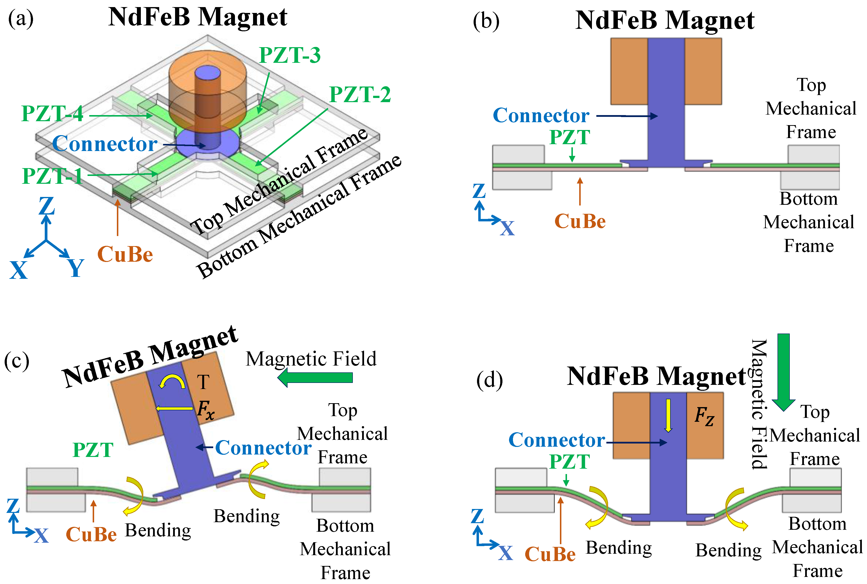
2. Design
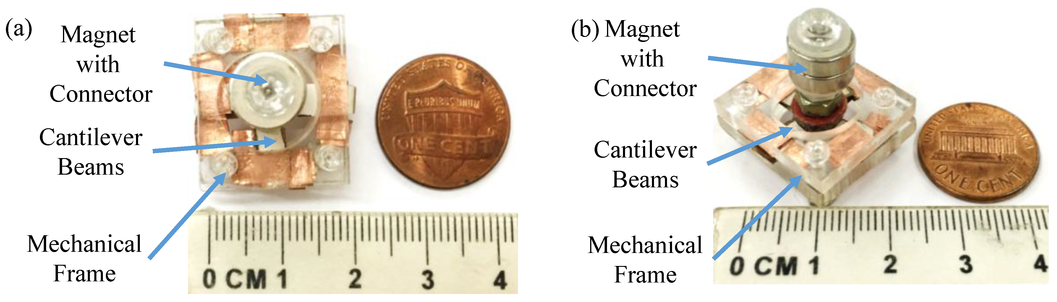
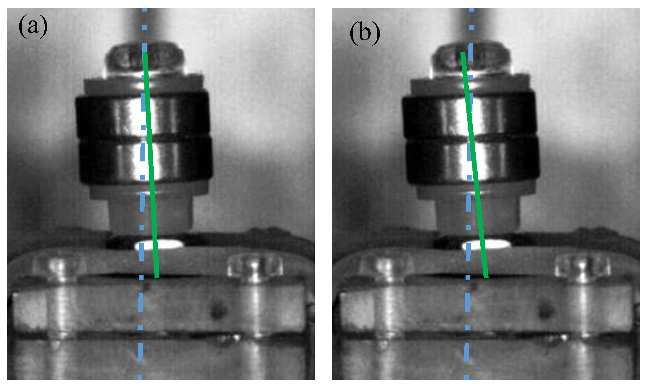
3. Fabrication
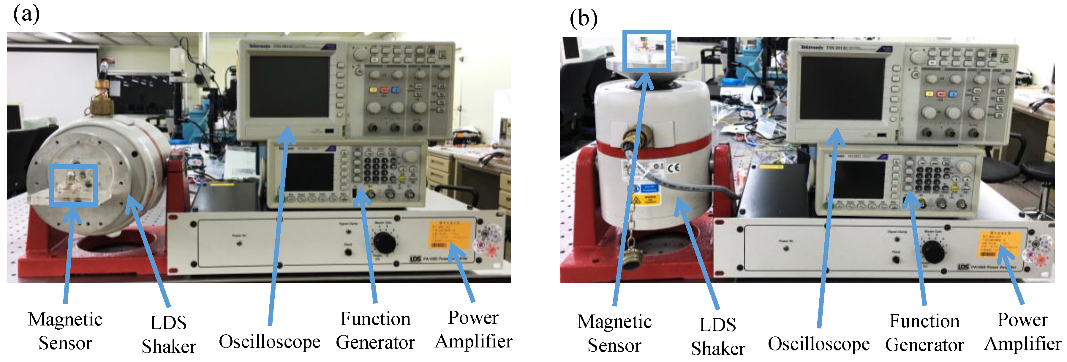
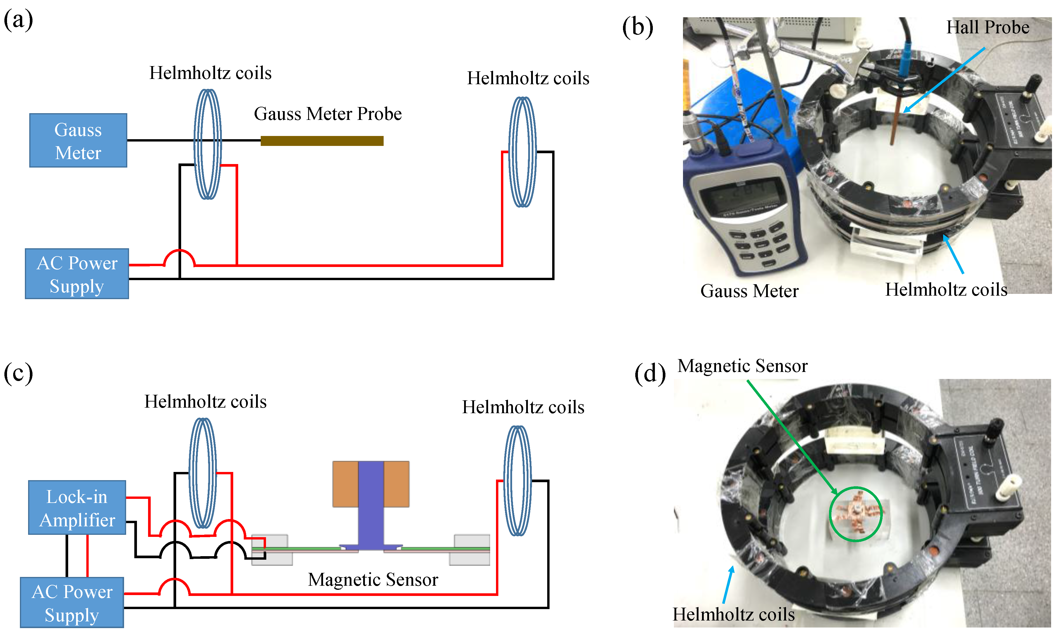
4. Testing
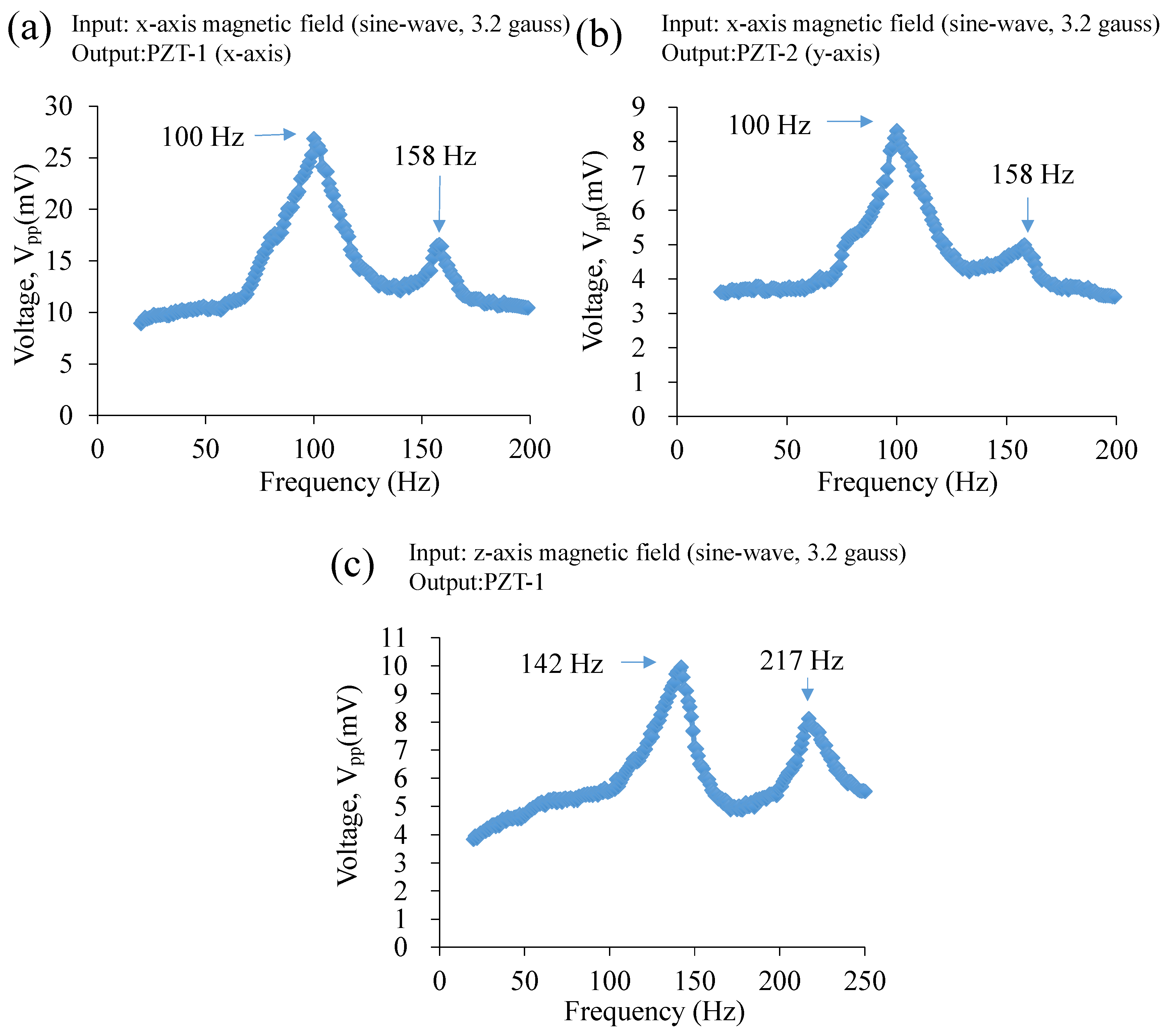
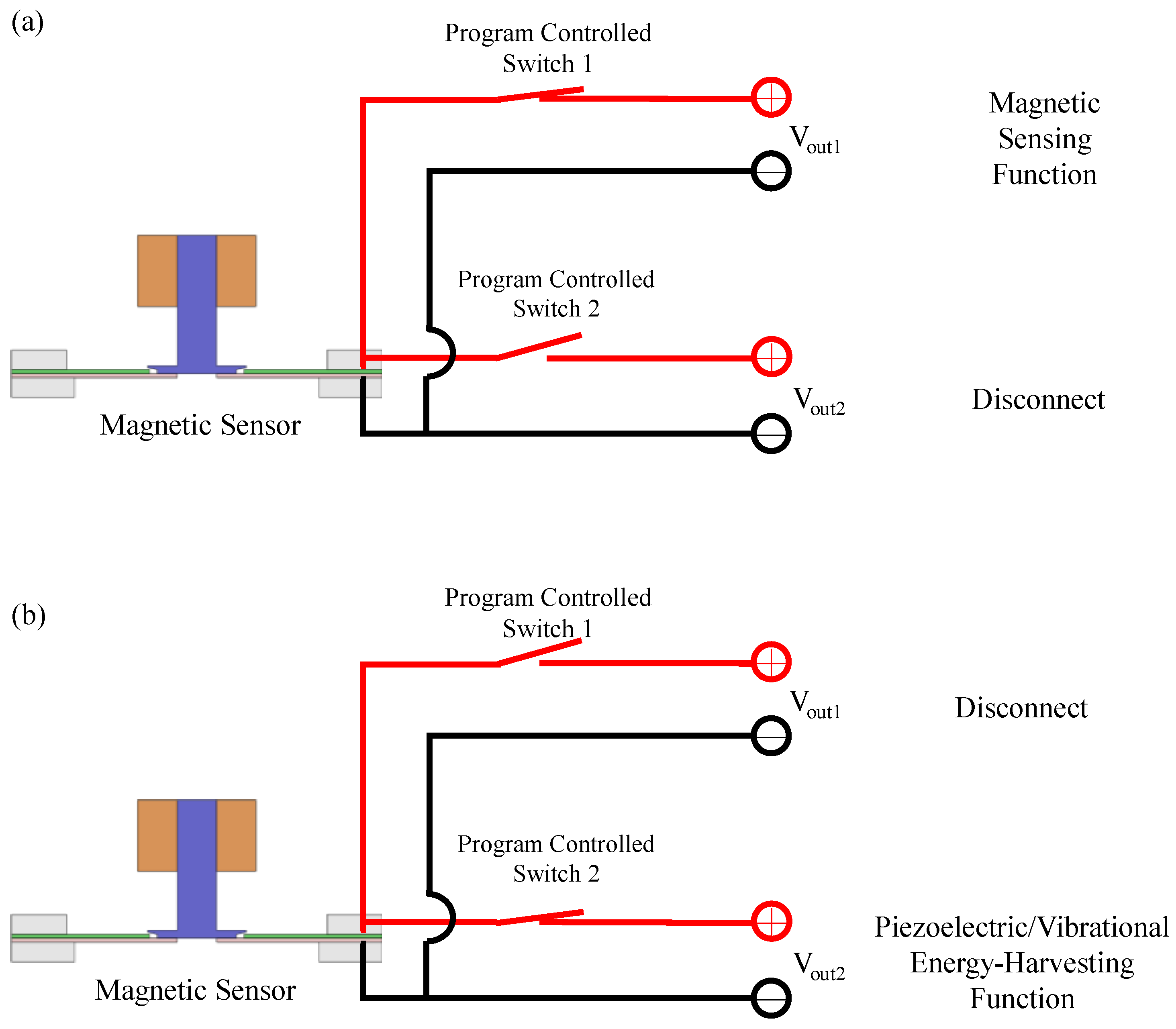
4.1. Magnetic Sensing Functions
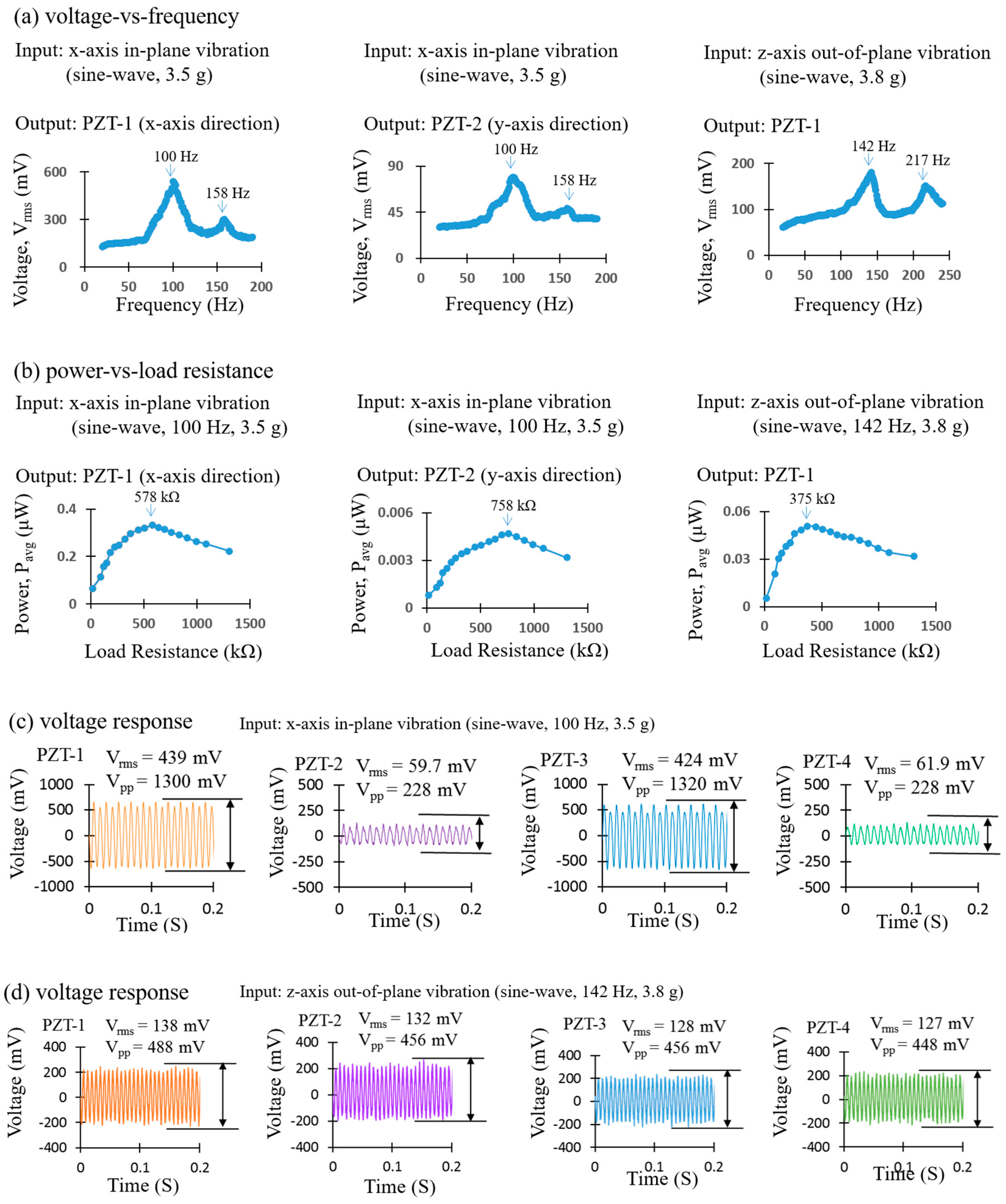
4.2. Piezoelectric/Vibrational-Energy-Harvesting Functions
5. Results and Discussion
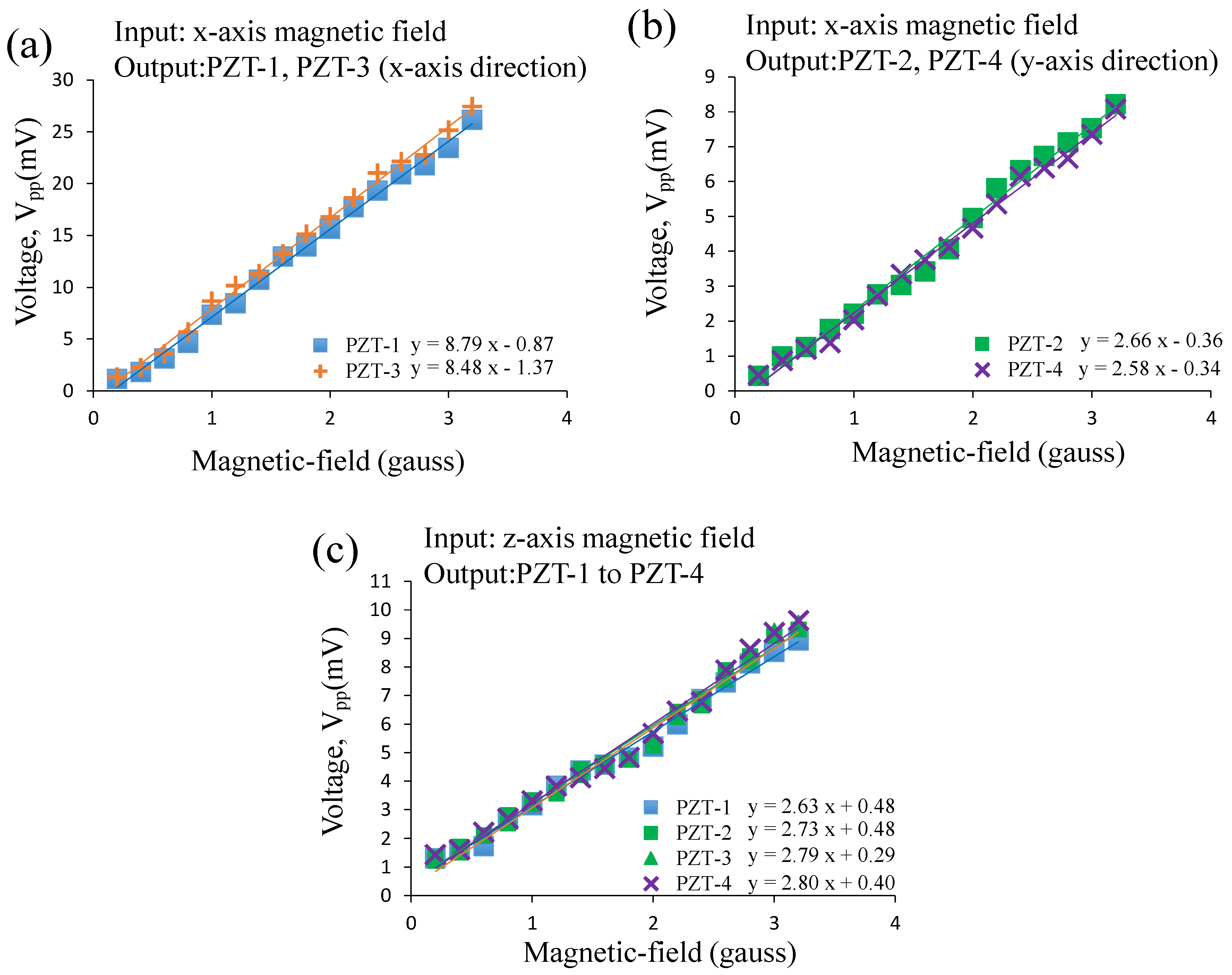
5.1. Magnetic-Sensing Functions
5.2. Piezoelectric/Vibrational Energy-Harvesting Functions
6. Conclusions
Supplementary Materials
Acknowledgments
Author Contributions
Conflicts of Interest
References
- Reig, C.; Cubells-Beltran, M.D.; Munoz, D.R. Magnetic Field Sensors Based on Giant Magnetoresistance (GMR) Technology: Applications in Electrical Current Sensing. Sensors 2009, 9, 7919–7942. [Google Scholar] [CrossRef] [PubMed]
- Ouyang, Y.; He, J.L.; Hu, J.; Wang, S.X. A Current Sensor Based on the Giant Magnetoresistance Effect: Design and Potential Smart Grid Applications. Sensors 2012, 12, 15520–15541. [Google Scholar] [CrossRef] [PubMed]
- Yeh, P.C.; Chung, T.K.; Lai, C.H.; Wang, C.M. A magnetic-piezoelectric smart material-structure utilizing magnetic force interaction to optimize the sensitivity of current sensing. Appl. Phys. A-Mater. Sci. 2016, 122, 29. [Google Scholar] [CrossRef]
- Jogschies, L.; Klaas, D.; Kruppe, R.; Rittinger, J.; Taptimthong, P.; Wienecke, A.; Rissing, L.; Wurz, M.C. Recent Developments of Magnetoresistive Sensors for Industrial Applications. Sensors 2015, 15, 28665–28689. [Google Scholar] [CrossRef] [PubMed]
- Wong, T.H.; Chung, T.K.; Liu, T.W.; Chu, H.J.; Hsu, W.Y.; Yeh, P.C.; Chen, C.C.; Lee, M.S.; Yang, Y.S. Electromagnetic/Magnetic-Coupled Targeting System for Screw-Hole Locating in Intramedullary Interlocking-Nail Surgery. IEEE Sens. J. 2014, 14, 4402–4410. [Google Scholar] [CrossRef]
- Lee, M.S.; Hsu, P.J.; Sun, A.; Wong, T.H.; Hsu, W.; Chung, T.K. A Removable Mechanism for Positioning Magnet for Distal Locking in Intramedullary Nailing Surgery. In Proceedings of the 14th International Federation for the Promotion of Mechanism and Machine Science World Congress (IFToMM 2015), Taipei, Taiwan, 25–30 October 2015.
- Chung, T.K.; Yeh, P.C.; Lee, H.; Lin, C.M.; Tseng, C.Y.; Lo, W.T.; Wang, C.M.; Wang, W.C.; Tu, C.J.; Tasi, P.Y.; et al. An Attachable Electromagnetic Energy Harvester Driven Wireless Sensing System Demonstrating Milling-Processes and Cutter-Wear/Breakage-Condition Monitoring. Sensors 2016, 16, 269. [Google Scholar] [CrossRef] [PubMed]
- SMART DIGITAL MAGNETOMETER HMR2300—Farnell. Available online: http://www.farnell.com/datasheets/46088.pdf (accessed on 13 January 2017).
- Fontana, M.; Salsedo, F.; Bergamasco, M. Novel Magnetic Sensing Approach with Improved Linearity. Sensors 2013, 13, 7618–7632. [Google Scholar] [CrossRef] [PubMed] [Green Version]
- Sanz, R.; Fernandez, A.B.; Dominguez, J.A.; Martin, B.; Michelena, M.D. Gamma Irradiation of Magnetoresistive Sensors for Planetary Exploration. Sensors 2012, 12, 4447–4465. [Google Scholar] [CrossRef] [PubMed]
- Chen, Y.J.; Yeh, P.C.; Chung, T.K. A Novel AMR Magnetic Sensor Utilizing Nanoscale Magnetic-Domain Transformation. In Proceedings of the IEEE International Magnetics Conference (INTERMAG), Beijing, China, 11–15 May 2015.
- Herrera-May, A.L.; Aguilera-Cortes, L.A.; Garcia-Ramirez, P.J.; Manjarrez, E. Resonant Magnetic Field Sensors Based On MEMS Technology. Sensors 2009, 9, 7785–7813. [Google Scholar] [CrossRef] [PubMed]
- Chung, T.K.; Wang, H.M.; Chen, Y.J.; Lin, S.H.; Chu, H.J.; Lin, P.J.; Hung, C.F. Magnetic-Field-Assisted Electric-Field-Controlled Rotation of Magnetic Stripe Domains in a Magnetoelectric Ni Microbar/[Pb(Mg1/3Nb2/3)O3]0.68-[PbTiO3]0.32 heterostructure. Appl. Phys. Express 2016, 9, 043003. [Google Scholar] [CrossRef]
- Garcia-Arribas, A.; Gutierrez, J.; Kurlyandskaya, G.V.; Barandiaran, J.M.; Svalov, A.; Fernandez, E.; Lasheras, A.; de Cos, D.; Bravo-Imaz, I. Sensor Applications of Soft Magnetic Materials Based on Magneto-Impedance, Magneto-Elastic Resonance and Magneto-Electricity. Sensors 2014, 14, 7602–7624. [Google Scholar] [CrossRef] [PubMed]
- Priya, S.; Ryu, J.; Park, C.S.; Oliver, J.; Choi, J.J.; Park, D.S. Piezoelectric and Magnetoelectric Thick Films for Fabricating Power Sources in Wireless Sensor Nodes. Sensors 2009, 9, 6362–6384. [Google Scholar] [CrossRef] [PubMed]
- Kreitmeier, F.; Chashin, D.V.; Fetisov, Y.K.; Fetisov, L.Y.; Schulz, I.; Monkman, G.J.; Shamonin, M. Nonlinear Magnetoelectric Response of Planar Ferromagnetic-Piezoelectric Structures to Sub-Millisecond Magnetic Pulses. Sensors 2012, 12, 14821–14837. [Google Scholar] [CrossRef] [PubMed]
- Marauska, S.; Jahns, R.; Kirchhof, C.; Claus, M.; Quandt, E.; Knochel, R.; Wagner, B. Highly sensitive wafer-level packaged MEMS magnetic field sensor based on magnetoelectric composites. Sens. Actuators A-Phys. 2013, 189, 321–327. [Google Scholar] [CrossRef]
- Regini, E.; Rosing, T.S. An Energy Efficient Wireless Communication Mechanism for Sensor Node Cluster Heads. In Proceedings of the 2009 International Conference on Intelligent Sensors, Sensor Networks and Information Processing (ISSNIP 2009), Melbourne, Australia, 7–10 December 2009.
- Chen, W.; Cao, Y.L.; Xie, J. Piezoelectric and electromagnetic hybrid energy harvester for powering wireless sensor nodes in smart grid. J. Mech. Sci. Technol. 2015, 29, 4313–4318. [Google Scholar] [CrossRef]
- Cui, N.Y.; Wu, W.W.; Zhao, Y.; Bai, S.; Meng, L.X.; Qin, Y.; Wang, Z.L. Magnetic Force Driven Nanogenerators as a Noncontact Energy Harvester and Sensor. Nano Lett. 2012, 12, 3701–3705. [Google Scholar] [CrossRef] [PubMed]
- Han, J.C.; Hu, J.; Wang, Z.X.; Wang, S.X.; He, J.L. Magnetoelectric effect in shear-mode Pb(Zr, Ti)O3/NdFeB composite cantilever. Appl. Phys. Lett. 2015, 106, 182901. [Google Scholar] [CrossRef]
- Yu, A.F.; Song, M.; Zhang, Y.; Kou, J.Z.; Zhai, J.Y.; Wang, Z.L. A self-powered AC magnetic sensor based on piezoelectric nanogenerator. Nanotechnology 2014, 25, 455503. [Google Scholar] [CrossRef] [PubMed]
- Chung, T.K.; Wang, C.M.; Yeh, P.C.; Liu, T.W.; Tseng, C.Y.; Chen, C.C. A Three-Axial Frequency-Tunable Piezoelectric Energy Harvester Using a Magnetic-Force Configuration. IEEE Sens. J. 2014, 14, 3152–3163. [Google Scholar] [CrossRef]
- Chen, C.C.; Chung, T.K.; Tseng, C.Y.; Hung, C.F.; Yeh, P.C.; Cheng, C.C. A Miniature Magnetic-piezoelectric Thermal Energy Harvester. IEEE Trans. Magn. 2015, 51, 9100309. [Google Scholar]
- Kunz, K.; Enoksson, P.; Stemme, G. Highly sensitive triaxial silicon accelerometer with integrated PZT thin film detectors. Sens. Actuators A-Phys. 2001, 92, 156–160. [Google Scholar] [CrossRef]
- Kanda, K.; Iga, Y.; Matsuoka, J.; Jiang, Y.G.; Fujita, T.; Higuchi, K.; Maenaka, K. A Tri-Axial Accelerometer with Structure-Based Voltage Operation by Using Series-Connected Piezoelectric Elements. In Proceedings of the 24th Eurosensor Conference, Linz, Austria, 5–8 September 2010.
- Hung, C.F.; Chung, T.K.; Yeh, P.C.; Chen, C.C.; Wang, C.M.; Lin, S.H. A Miniature Mechanical-Piezoelectric-Configured Three-Axis Vibrational Energy Harvester. IEEE Sens. J. 2015, 15, 5601–5615. [Google Scholar] [CrossRef]
- Three-Axis Magnetic Sensor HMC1043L. Available online: https://aerospace.honeywell.com/~/media/aerospace/files/datasheet/hmc1043l_3-axis_magnetic_sensor_preliminary.pdf (accessed on 13 January 2017).
- Seidel, M.; Paprotny, I.; Krishnan, K.; White, R.; Evans, J. AMR Current Sensors for Evaluating the Integrity of Concentric Neutrals in In-Service Underground Power Distribution Cables. In Proceedings of the Conference Record of the 2010 IEEE International Symposium on Electrical Insulation (ISEI), San Diega, CA, USA, 6–9 June 2010.
- Sosnicki, O.; Porchez, T.; Michaud, G.; Bencheikh, N.; Claeyssen, F. AC magnetic field detection system applied to motion tracking. In Proceedings of the Sensoren und Messsysteme 2010-15, ITG/GMA-Fachtagung, Nürnberg, Germany, 18–19 May 2010.
- Yasuhide, S.; Fumio, N. Dynamic bending/torsion and output power of S-shaped piezoelectric energy harvesters. Int. J. Mech. Mater. Des. 2014, 10, 305–311. [Google Scholar]
- Li, M.; Rouf, V.T.; Thompson, M.J.; Horsley, D.A. Three-Axis Lorentz-Force Magnetic Sensor for Electronic Compass Applications. J. Microelectromech. Syst. 2012, 21, 1002–1010. [Google Scholar] [CrossRef]
- Roundy, S.; Wright, P.K. A piezoelectric vibration based generator for wireless electronics. Smart Mater. Struct. 2004, 13, 1131–1142. [Google Scholar] [CrossRef]
- Sensor Solutions for Automotive, Industrial and Consumer Applications. Available online: http://www.infineon.com/dgdl/Infineon-Sensor_Solutions_for_Automotive_Industrial_and+Customer_Appl_BR-2015.pdf?fileId=5546d4614937379a01495212845c039f (accessed on 24 January 2017).
- Goh, K.M.; Chan, H.L.; Ong, S.H.; Moh, W.P.; Tows, D.; Ling, K.V. Wireless GMR Sensor Node for Vibration Monitoring. In Proceedings of the 5th IEEE Conference on Industrial Electronics and Applications, Taichung, Taiwan, 15–17 June 2010.
- Hall Effect Differential Gear Tooth Sensors CYGTS101DC-S. Available online: http://www.hallsensors.de/CYGTS101DC-S.pdf (accessed on 24 January 2017).


| The Sensor and Components | Size | Weight |
|---|---|---|
| Sensor | (length × width × thickness) | 7.1 g |
| 2 × 2 × 2 cm3 | ||
| CuBe Sheet | (length × width × thickness) | 0.01 g |
| (sandwiched by mechanical clamp) | 3.5 × 3.5 × 0.25 mm3 | |
| PZT Sheet | (length × width × thickness) | 0.06 g |
| (sandwiched by mechanical clamp) | 3.5 × 3.5 × 1 mm3 | |
| CuBe Sheet | (length × width × thickness) | 0.02 g |
| (outside of mechanical clamp) | 5.5 × 3.5 × 0.25 mm3 | |
| PZT Sheet | (length × width × thickness) | 0.07 g |
| (outside of mechanical clamp) | 4 × 3.5 × 1 mm3 | |
| Magnet | (radius2 × π × high) | 2.27 g |
| 4.352 × π × 6 mm3 | ||
| With a 12 × π × 6 mm3 hole | ||
| Connector | (radius2 × π × high) | 0.01 g |
| 4.02 × π × 0.49 mm3 |
| Magnetic Sensors | Our Sensor | Han et al. [21] | Yu et al. [22] |
|---|---|---|---|
| Features | Three-Axis | Single-Axis | Single-Axis |
| VolMS (mm3) | 103.27 | 2460 a | 1733.33 a |
| VolSensor (mm3) | 8000 | 25,800 a | 36,000 a |
| Sin-plane (mV/gauss) | PZT-1: 8.79 PZT-3: 8.48 | Sample S1 b: 790 a Sample S2 b: 920 a Sample S3 b: 960 a | N/A |
| Normalized Sin-plane by VolMS c | PZT-1: 1.02 e PZT-3: 0.98 e | Sample S1 b: 3.84 a,e Sample S2 b: 4.48 a,e Sample S3 b: 4.66 a,e | N/A |
| Normalized Sin-plane by VolSensor d | PZT-1: 1.02 e PZT-3: 0.98 e | Sample S1 b: 9.46 a,e Sample S2 b: 11.01 a,e Sample S3 b: 11.49 a,e | N/A |
| Sout-of-plane (mV/gauss) | PZT-1: 2.63 PZT-2: 2.73 PZT-3: 2.79 PZT-4: 2.80 | N/A | 7 a |
| Normalized Sout-of-plane by VolMS c | PZT-1: 0.96 f PZT-2: 0.99 f PZT-3: 1.01 f PZT-4: 1.02 f | N/A | 0.15 a,f |
| Normalized Sout-of-plane by VolSensor d | PZT-1: 0.96 f PZT-2: 0.99 f PZT-3: 1.01 f PZT-4: 1.02 f | N/A | 0.19 a,f |
© 2017 by the authors. Licensee MDPI, Basel, Switzerland. This article is an open access article distributed under the terms and conditions of the Creative Commons Attribution (CC BY) license ( http://creativecommons.org/licenses/by/4.0/).
Share and Cite
Hung, C.-F.; Yeh, P.-C.; Chung, T.-K. A Miniature Magnetic-Force-Based Three-Axis AC Magnetic Sensor with Piezoelectric/Vibrational Energy-Harvesting Functions. Sensors 2017, 17, 308. https://doi.org/10.3390/s17020308
Hung C-F, Yeh P-C, Chung T-K. A Miniature Magnetic-Force-Based Three-Axis AC Magnetic Sensor with Piezoelectric/Vibrational Energy-Harvesting Functions. Sensors. 2017; 17(2):308. https://doi.org/10.3390/s17020308
Chicago/Turabian StyleHung, Chiao-Fang, Po-Chen Yeh, and Tien-Kan Chung. 2017. "A Miniature Magnetic-Force-Based Three-Axis AC Magnetic Sensor with Piezoelectric/Vibrational Energy-Harvesting Functions" Sensors 17, no. 2: 308. https://doi.org/10.3390/s17020308