Advances in Remote Sensing for Oil Spill Disaster Management: State-of-the-Art Sensors Technology for Oil Spill Surveillance

1
Department of Geomatics Engineering, University of Calgary Calgary, Alberta, Canada T2N 1N4
2
Western Washington University, Disaster Reduction and Emergency Planning, Huxley College of the Environment, 516 High Street, Bellingham, Washington 98225-9085 USA
*
Author to whom correspondence should be addressed.
Sensors 2008, 8(1), 236-255; https://doi.org/10.3390/s8010236
Submission received: 22 December 2007
/
Accepted: 10 January 2008
/
Published: 21 January 2008
(This article belongs to the Special Issue Sensors for Disaster and Emergency Management Decision Making)
Abstract
:Reducing the risk of oil spill disasters is essential for protecting the environment and reducing economic losses. Oil spill surveillance constitutes an important component of oil spill disaster management. Advances in remote sensing technologies can help to identify parties potentially responsible for pollution and to identify minor spills before they cause widespread damage. Due to the large number of sensors currently available for oil spill surveillance, there is a need for a comprehensive overview and comparison of existing sensors. Specifically, this paper examines the characteristics and applications of different sensors. A better understanding of the strengths and weaknesses of oil spill surveillance sensors will improve the operational use of these sensors for oil spill response and contingency planning. Laser fluorosensors were found to be the best available sensor for oil spill detection since they not only detect and classify oil on all surfaces but also operate in either the day or night. For example, the Scanning Laser Environmental Airborne Fluorosensor (SLEAF) sensor was identified to be a valuable tool for oil spill surveillance. However, no single sensor was able to provide all information required for oil spill contingency planning. Hence, combinations of sensors are currently used for oil spill surveillance. Specifically, satellite sensors are used for preliminary oil spill assessment while airborne sensors are used for detailed oil spill analysis. While satellite remote sensing is not suitable for tactical oil spill planning it can provide a synoptic coverage of the affected area.
1. Introduction
Petroleum products play an important role in modern society, particularly in the transportation, plastics, and fertilizer industries. There are typically ten to fifteen transfers involved in moving oil from the oil field to the final consumer. Oil spills can occur during oil transportation or storage and spillage can occur in water, ice or on land Marine oil spills can be highly dangerous since wind, waves and currents can scatter a large oil spill over a wide area within a few hours in the open sea (Fingas, 2001). Between 1988 and 2000, there were 2,475 spills which released over 800,000 liters of oil in Toronto and surrounding regions (Li, 2002). An oil spill may be due to a number of reasons, including transportation accidents. In addition to accidents, the controlled release of oil by shipping operators and oil production platforms are major sources of oil spills (Grüner,1991). Environmental rules, regulations and strict operating procedures have been imposed to prevent oil spills, but these measures cannot completely eliminate the risk (Fingas, 2001).
Once oil is spilled, it quickly spreads to form a thin layer on the water surface, known as an “oil slick”. As time passes, the oil slick becomes thinner, forming a layer known as a “sheen” which has a rainbow like appearance. Light oils are highly toxic but evaporate quickly. Heavy oils are less toxic but persist in the environment for a long time. Heavy oils can get mixed with pebbles and sandy beaches where they may remain for years (Environment Canada, 2007). Worldwide, fuels account for 48% of the total oil spilled into the sea worldwide, while crude oil spills account for 29% of the total (Brekke and Solberg, 2005). The environmental impacts of oil spills can be considerable. Oil spills in water may severely affect the marine environment causing a decline in phytoplankton and other aquatic organisms. Phytoplankton is at the bottom of the food chain and can pass absorbed oil on to higher levels in the food chain. Oiled birds suffer from behavioral changes and this may result in the loss of eggs or even death (Figure 1). The livelihood of many coastal people can be impacted by oil spills, particularly those whose livelihood is based on fishing and tourism (NOAA, 2007). The movement of oil on land depends on various factors such as oil type, soil type and moisture content of the soil. Oil spilled on agricultural land can impact soil fertility and pollute ground water resources (Fingas, 2001).
Oil companies and shipping operators are responsible for controlling spilled oil and cleaning polluted areas. In the event of an oil spill, information about the size and extent of the spill is critical to assist the government and industry in oil spill contingency planning. Fingas (2001) describes the guidelines for estimating oil thickness using visual surveillance as shown in Table 1. The appearance of oil varies from silvery-sheen to dark brown.
Visual detection of an oil spill is not reliable as oil can be confused with other substances, e.g. sea weeds and fish sperm. Moreover, oil on the surface cannot be observed clearly through fog and darkness (Fingas, 2001). Remote sensing can be used for detecting and monitoring oil spills. Remote sensing technologies for oil spill surveillance have been reviewed by many authors. Goodman (1994) notes that the operational use of remote sensing for oil spill contingency planning is limited although simple systems (i.e. UV/IR systems and Radar) have been used to some extent for responding to oil spills. Laser Fluorosensors can detect oil under the water surface and on various backgrounds including snow or ice (Brown and Fingas, 2003a). Brown and Fingas (1997) found that no single sensor can give all the information required for oil spill contingency planning. Currently, many coastal nations have proper maritime surveillance systems in place to detect and monitor oil spill (Brown and Fingas, 2005). The remainder of the paper is organized as follows. In Section 2, we provide an overview of remote sensing technologies for oil spill surveillance. In Section 3, we evaluate these systems on the basis of their effectiveness for providing appropriate information for oil spill contingency planning. Conclusions are provided in Section 4.
2. Remote Sensing for Oil Spill Surveillance
There are many sensors available to detect oil spills on various kinds of surfaces. Multi-temporal imaging captured by remote sensing sensors can provide important information required to model the spread of an oil spill (Natural Resources Canada, 2007). Oil spill models may be useful for cleanup operations and controlling the oil spill. Remote sensing devices for oil spill detection include infrared video and photography, thermal infrared imaging, airborne laser fluorosensors, airborne and space-borne optical sensors, and airborne and space-borne SAR (Natural Resources Canada, 2007). Satellite remote sensing suffers from low spatial and temporal resolution although it provides a synoptic view and a more cost effective system than an airborne platform, which is typically used for oil spill surveillance. Sensors can provide the following information for oil spill contingency planning (Grüner, 1991):
- The location and spread of an oil spill over a large area
- The thickness distribution of an oil spill to estimate the quantity of spilled oil
- A classification of the oil type in order to estimate environmental damage and to take appropriate response activities
- Timely and valuable information to assist in clean-up operations
Remote sensing bands and related instruments for oil spill detection are shown (Table 2). However, infrared, visible and UV sensors will not be able to detect oil in inclement weather such as heavy rain or fog (Goodman, 1994). Visible sensors are generally used to create a base map for the oil spill. A brief description of sensors useful for oil spill detection is given in the following sections.
a) Visible Sensors
Thermal and visible scanning systems as well as aerial photography were commonly used airborne remote sensing sensors at the start of 1970 (Wadsworth, 1992). Visible sensors (passive sensors operating in the visible region of the light) are still widely used in oil spill remote sensing despite many shortcomings. The reflectance of oil is higher than that of water but oil also absorbs some radiation in the visible region. These sensors are not good for oil detection as it is difficult to distinguish oil from the background (Figure 2). Sun-glint and wind sheen may create a similar impression to an oil sheen. Moreover, sea weeds and a darker shoreline may be mistaken for oil. Visible sensors can not normally operate at night as they are based on the reflectance of sunlight. Visible sensors are useful only for documentation purposes as there are no methods to ensure the positive detection of an oil spill. Visible sensors are widely available and can be easily mounted on aircraft. Video cameras possess a lower resolution than still cameras but are still in widespread use for oil spill remote sensing. Visible sensors are less costly and easy to use; therefore, they are often used to create the basic data in coastal areas (Brown and Fingas, 1997; Goodman, 1994).
Improvements in sensor technologies have led to the development of hyperspectral sensors such as Airborne Visible/Infrared Imaging Spectrometer (AVIRIS) and Airborne Imaging Spectrometer for Applications (AISA). A hyperspectral image consists of ten to hundreds of spectral bands and can provide a spectral signature for an object. However, conventional techniques for multispectral data analysis cannot be used to investigate hyperspectral images (Landgrebe, 2003). Plaza et al. (2001) and Salem and Kafatos (2001) have reported the use of hyperspectral data for oil spill detection. The extensive spectral information can be used to discriminate between light and crude oil. Minute concentrations of crude oil can be detected using hyperspectral images.
b) Infrared Sensors
Infrared sensors are passive sensors. The oil absorbs solar radiation and emits some part of it as the thermal energy mainly in the thermal infrared region (8-14 μm). Oil has a lower emissivity than water in the thermal infrared region (TIR) and therefore oil has a distinctively different spectral signature in the thermal infrared region compared to the background water (Salisbury et al., 1993). TIR is typically used for oil spill detection in the IR region. Thick oil absorbs greater amounts of radiation and as a result it appears hot in TIR. The oil of intermediate thickness appears cool in this region, but thin sheens can not be detected in TIR. The thickness of the minimum detectable layer lies between 20 and 70 μm. The change from hot to cold layer occurs between 50 and 150 μm (Brown and Fingas, 1997). At night, the reverse behavior is observed: heat loss in oil is faster than in water and therefore, thick oil appears cooler than water (Samberg, 2005). Thus, infrared sensors can provide some information about the relative thickness of oil slicks. These sensors are unable to detect emulsions of oil in water as emulsions contain 70% of water and thermal properties of emulsion are similar to the background water (Brown and Fingas, 1997).
Thermal radiation from sea weeds and the shoreline appear similar to the radiation arising from the oil which may lead to a false positive result. The infrared sensors are relatively cheap remote sensing technologies which can be used to detect oil spills and are hence widely used systems for oil spill surveillance (Brown and Fingas, 2005).
c) Ultraviolet Sensors
UV scanners capture the ultraviolet radiation reflected by the sea surface. A UV sensor is a passive sensor as it uses reflected sunlight in the ultraviolet region (0.32-0.38 micron) for detecting oil spills. Oil has stronger reflectivity than water in the UV region. Even a very thin oil film has a strong reflectance in the UV region. Very thin sheens of thickness (less than 0.1 micron) can be detected using a UV sensor. However, UV sensors cannot detect oil thickness greater than 10 micron. UV images can only give information about the relative thickness of the oil slick (Grüner, 1991).
False detection may occur due to the wind sheen, sun glint and sea weeds. Interferences in UV are different from IR and a combination of these two techniques can provide improved results for oil spill detection (Brown and Fingas, 1997; Goodman, 1994). The ultraviolet images can be overlayed with infrared images to generate an oil spill relative thickness map. UV images are based on the reflected sunlight and hence cannot operate in the night.
d) Radar
Radar is an active sensor and operates in radio wave region. Radar waves are reflected by capillary waves on the ocean and therefore, a bright image is obtained for ocean water. Oil diminishes capillary waves and as a result, if oil is present in the ocean then reflectance is reduced. Hence, the presence of oil can be detected as dark part in the bright image for the ocean (Brown et al., 2003). Radar is very useful as it can be used to detect oil over a large area. Thus, it can be used as a first assessment tool to detect the possible location of an oil spill. Radar can work in both inclement weather and at night. SAR (Synthetic Aperture Radar) and SLAR (Side- Looking Airborne Radar) are the two most common types of Radar which can be used for oil spill remote sensing. SAR has superior spatial resolution and range than SLAR (Brown and Fingas, 1997). However, SLAR is less expensive and predominantly used for airborne remote sensing. Wismann et al. (1998) found that the dampening of capillary waves by thick oil is higher than the oil sheen and hence sheens can be distinguished from thicker oils. A SAR image captured by RADARSAT-1 is shown in Figure 3. It can be seen that the shoreline also provides a similar impression as oil slicks in the SAR image. Moreover, calm water in the SAR image also appears dark which gives the false impression of oil.
The interference may be due to the presence of organic substances other than oils which produce films on the sea surface. Seaweed creates this type of film and may lead to a false alarm in the radar image. Both very low and very high wind speeds influence oil spill detection. At high wind speed, even thick oil slicks are dispersed into the water column and oil cannot be detected. At low wind speed it is not possible to distinguish between thick and thin oil slicks. Jones (2001) observed that an oil slick can be detected between wind speeds of 2-12 m/s. However, wind speeds of 5-6 m/s are optimal for oil spill detection. SAR is the most widely used sensor on space-borne platforms for oil spill detection.
e) Microwave
MWR (Microwave radiometer) is a passive sensor and is used for oil spill detection and oil thickness measurements. Oil emits stronger microwave radiation than water and appears brighter than the water (which is dark in the background). Measuring oil thicknesses with MWR involves the interference of radiation from the upper and lower boundaries of the oil film. Microwave emission is highest when oil film thickness is equal to an odd multiple of one quarter of the wavelength of the emitted energy. This may lead to an estimation of multiple values of thickness for a given signal. This cyclical estimation problem for oil spills was solved in the new breed of MWR sensors (Brown and Fingas, 1997). Biogenic materials can produce similar signals to oil which may lead to a false alarm. This sensor can work well in adverse weather conditions. MWR sensors can work in both the day and the night. MWR requires a special antenna to receive emitted microwave radiation. Accordingly, there is a requirement for dedicated aircraft. MWR sensors are costly and it is complicated to put them into operation. MWR sensors require information about many environmental characteristics and oil properties in order to accurately detect the oil. The main disadvantage of using the MWR sensor is the low spatial resolution.
f) Laser fluorosensor
Certain aromatic hydrocarbon compounds in petroleum oils absorb laser-induced UV light to become electronically excited. The excitation is released through fluorescence emission by the compound mainly in the visible region. A multi-channel receiver is used to record the fluorescence spectrum (Goodman, 1994). Fluorescence spectrum of gelbstoff and phytoplankton look different from that of petroleum oils. Moreover, different types of oils have distinct fluorescence emission signature which allows for reliable oil identification (Figure 4). Oils can be classified also on the basis of fluorescence decay time (Goodman, 1994). The energy transfer between incident light and water molecules is known as Raman scattering. If the excitation wavelength is 308 nm (XeCl laser) then the Water Raman Signal is observed at 344 nm (Figure 5). The Water Raman signal is useful for fluorescence calibration as well as for estimating oil thickness to some extent (Brown and Fingas, 2003a).
To obtain the oil thickness from the Raman signal depression data, the following data must be known (Figure 6):
- (1)
- Seawater background fluorescence from organic materials
- (2)
- Oil fluorescence
The ratio of the Raman intensity measured above the oil slick and the Raman intensity measured outside the oil slick is a function of thickness (d) of the oil film and the attenuation coefficient of the oil film. The attenuation coefficient of the oil depends upon the oil type. The relation can be represented in Equation 1 (Hoge and Swift, 1980).
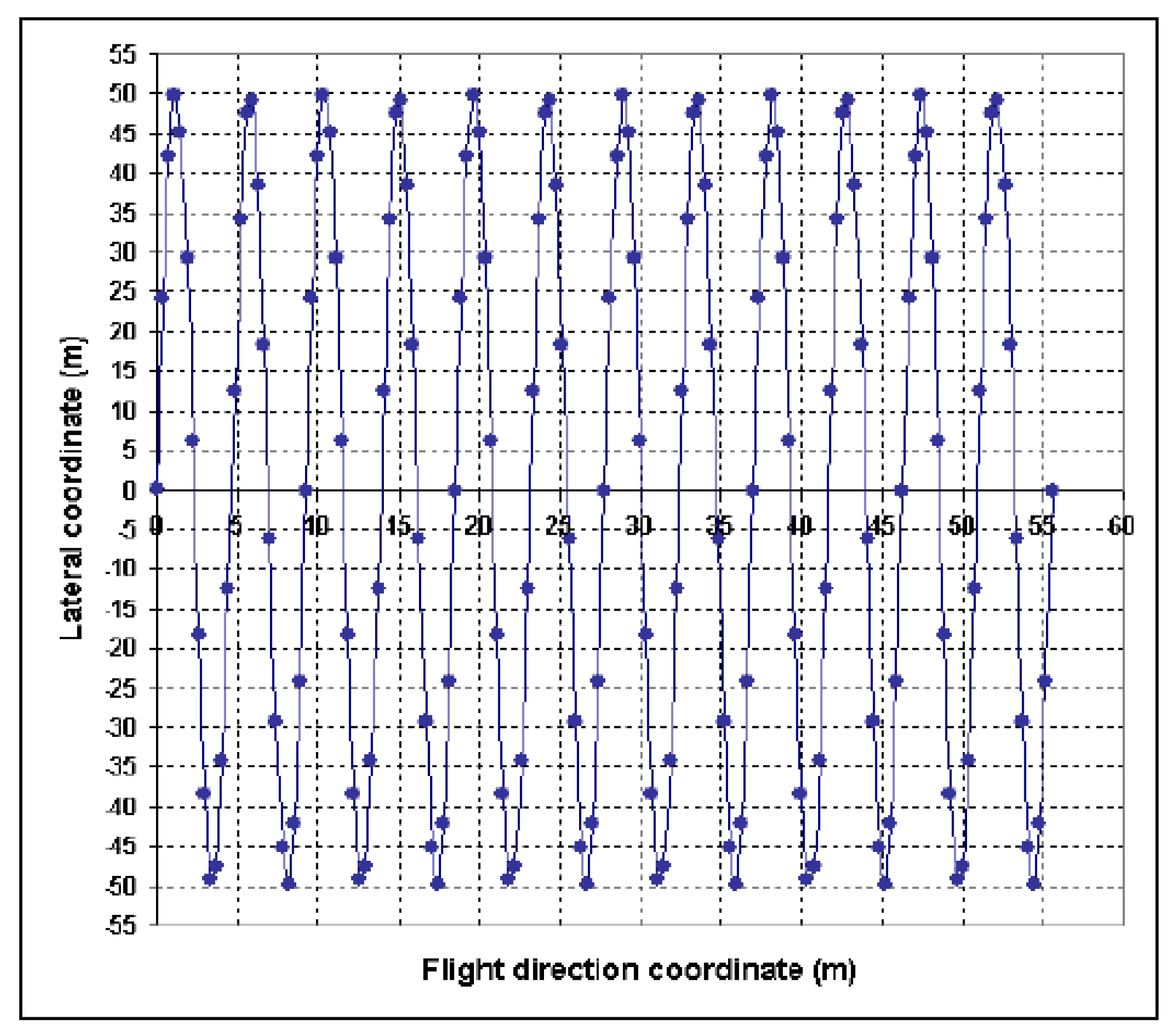
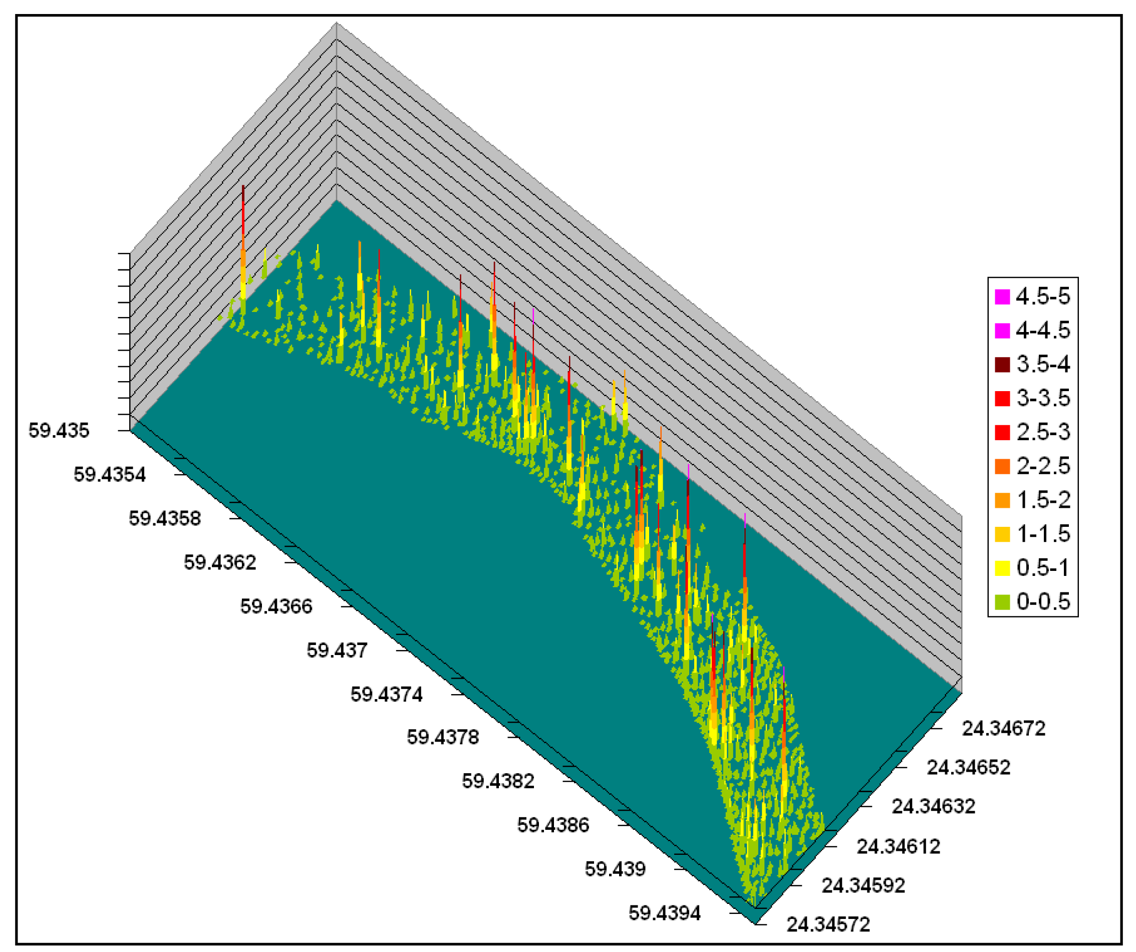
The laser fluorosensor is the most useful and reliable instrument to detect oil on various backgrounds including water, soil, weeds, ice and snow. They are the only reliable sensors to detect oil in the presence of ice or snow (Zielinski et al., 2001 and Brown and Fingas, 2003a). The laser fluorosensor signals also contain information about some ecologically relevant properties including seawater attenuation coefficients; phytoplankton and gelbstoff concentrations (i.e. dissolved organic matter). These parameters are useful to describe the ecological state of coastal waters (Brown and Fingas, 2003a). Laser fluorosensor was found to successfully detect water-in-oil emulsions whereas other sensors including UV, IR, and MWR have problems in detecting these emulsions (Brown et al., 2004b). Laser fluorosensors can be used for day and night operations. The atmosphere should be reasonably clear for the operational use of laser fluorosensors. The excitation wavelength for the laser is typically chosen as 308 or 355 nm (Grüner, 1991). A typical laser footprint of FLS LIDAR is shown in (Figure 7) and a processed laser fluorosensor dataset for a single flight line is shown in Figure 8.
Some prominent research centers working on laser fluorosensors are following:
- ESTD (Emergency Science and Technology Division), Environment Canada
- University of Oldenburg, Germany
- ENEA, Italy
- IROE-CNR, France
- NASA Oceanographic LIDAR project
- Laser Diagnostic Instruments AS
The development and testing of laser fluorosensors has occurred in Canada since 1970. Currently Environment Canada uses the Scanning Laser Environmental Airborne Fluorosensor (SLEAF) for oil spill surveillance. SLEAF has been tested successfully by Environment Canada in oil spill situations (Brown et al., 2004a and Brown et al., 2006b). The U.S. Coast Guard has tested three laser fluorosensor systems for subsurface oil spill detection (Fant and Hensen, 2006). They found that all three systems were successful in detecting surface and subsurface refined oil but results were not encouraging for the real time detection of California crude oil. This may be due to the problems in the algorithms for detecting heavy oils in those systems.
g) Laser-acoustic oil thickness sensor
This sensor detects the oil based on its acoustic or mechanical properties rather than its optical and electromagnetic properties. Absolute oil thickness can be measured by using this technique. The laser-acoustic sensor is an active sensor and can operate day and night (Goodman, 1994). Research and development of the Laser-Ultrasonic Remote Sensing of Oil Thickness (LURSOT) sensor has been undertaken by a group of agencies comprising Environment Canada, National Research Council of Canada, the Industrial Materials Institute, Imperial Oil Limited, and the United States Minerals Management. The time taken by ultrasonic waves to travel in oil is measured by three lasers and the oil thickness can be computed by using this time of flight. Brown and Fingas (2003b) found that results of laboratory tests of measuring oil thickness using LURSOT sensor indicate great potential. In 2006, the LURSOT system was successfully tested for oil slick thickness measurements from an aircraft by Environment Canada (Brown et al., 2006). However, Laser-acoustic sensors are bulky and expensive and cannot work in fog or cloud.
h) Satellite Remote Sensing
There have been serious efforts to use satellite remote sensing instead of airborne remote sensing for oil spill tactical or short-term response. However, there are many problems associated with using satellite remote sensing in place of airborne remote sensing. The main problem is the timing and frequency of the overpass. Moreover, satellite remote sensing demands a clear sky and good weather conditions. However, at the time of an overpass, clear conditions may not be present. Another major problem in using satellite remote sensing is the long time required for processing the dataset, which may disrupt oil spill contingency planning. In the past, satellite remote sensing was only used when the position of the oil spill was already known (Brown and Fingas, 1997). Also, satellite remote sensing has a lower spatial resolution than airborne remote sensing. Another limitation in using space-borne sensors is that very few sensors such as visible and Radar can be used on a space-borne platform (Brown and Fingas, 2001a). Many sensors like laser fluorosensors and IR sensors can not be operated on a spaceborne platform due to high atmospheric absorption and scattering (Brown et al., 2003). SAR is the most extensively used space-borne sensor for oil spill detection; however, detection is subject to interference (Olsen et al., 1995).
Satellite imagery is used for oil spill strategic planning rather than tactical planning (Fingas and Brown, 2005). Many countries in northern Europe use a combination of satellite sensors and airborne sensors for oil spill surveillance in the marine environment (Brekke and Solberg, 2005). Airborne sensors are used for short term or tactical response. Airborne sensors provide flexibility in terms of deployment time and choices of sensors. Satellite sensors provide a synoptic view of the affected area (Brown and Fingas, 2005). Efforts have been made to use satellite imagery for tactical planning. Lunel (1996) notes that SAR Satellite images were not available in the first week of the Sea Empress oil spill in the UK. Once available, the SAR images suffered from false detection and hence could not provide useful information for oil spill response. Simecek-Beatty and Pichel (2006) investigated the use of RADARSAT-1 SAR imagery for oil spill monitoring in Unalaska Island, Alaska. Tasking of the satellite for capturing imagery in the oil spill area was successful. The oil slick detection results were disappointing which may be due to the false alarm by a large number of biogenic films present near the Island. Some recently launched space-borne sensors like RADARSAT-2 have improved spatial resolution and an emergency feature in RADARSAT-2 allows for the tasking of satellites to the site of an oil spill in less time.
3. Comparison of Remote Sensing Systems for Oil Spill Response
Sensors can be compared based on various oil spill surveillance criteria. Specifically, the spatial resolution of the sensors can be important factor. Brown and Fingas (2001) note that the width of a typical oil spill window is less than 10 meters and hence the spatial resolution of sensors should be at least 10 meters. The timeframe for collecting and processing the data is very important for oil spill surveillance and monitoring. Data should be available in real time and allow for easy interpretation and use. Time is particularly critical for an oil spill occurring in the open ocean as wind and current can rapidly spread the oil over a large area in a short time. Goodman (1994) notes that any remote sensing data which is available only after 2-3 hours of oil spill is of little use. Brown et al. (2003) mention that remote sensing data should be available within one hour of the oil spill occurrence. The minimum spatial resolution and time requirement for various tasks in oil spill monitoring is given in Table 3. The spatial resolution and time required to process and analyze the data for some existing sensors is given in Table 4. Note that existing airborne sensors have greater spatial and temporal resolution than the space-borne sensors. Since time is a critical factor (due to dynamic nature of oil spills) airborne sensors are currently used for tactical response. Visible sensors are the best in terms of having a high spatial resolution.
Sensors capturing a synoptic view of the area are desirable and will help in monitoring the oil spill over a large area. Radar sensors (SAR and SLAR) can capture a large area and are very useful for providing general view of affected area (Table 4). While satellite remote sensing can capture a large area it suffers from low spatial resolution.
Sensors should be operational in day and night in order to constitute an effective surveillance system. Oil spill monitoring may be needed at any time. Accordingly, sensors should have the capability to operate during the night. Visible and UV sensors cannot work at night and this is the great disadvantage associated with using them. The effect of weather conditions such as rain and fog should be limited. Radar sensors are the best sensors for oil spill surveillance in adverse weather conditions. It is important that detection is not significantly affected by wind speed or sea conditions. Oil spill detection from Radar images are affected by wind speeds and these images are useful for only a small wind window. The cost and size of sensors can also play significant role in using sensors for oil spill surveillance. IR sensors are cheap and this has led to their widespread use for oil spill surveillance. Advanced sensors such as laser fluorosensors are very costly which makes their operational use difficult. Moreover, most of the advanced sensors require a dedicated aircraft which makes them even more expensive to operate. Some sensors like UV and IR can be easily mounted on aircraft and that makes operational use of these sensors convenient. The major problem with most of the sensors used for oil spill is false detection (due to sea weed, sun sheen etc). The detection of oil slicks by laser fluorosensors is unaffected by sea weed, sun sheen and other factors that can yield a false positive result. Laser fluorosensors are also the only sensor which can detect oil on various backgrounds including ice or snow. Detecting an oil spill on the shoreline is extremely important for cleaning operations and the laser fluorosensor is the only sensor which can positively detect oil on shorelines.
Oil can be classified into heavy, medium and light crude or refined oil. Once classified, it is easier to respond to the oil spill and to model the oil spill drift and spreading. For example, light oil such as diesel evaporates quickly whereas the evaporation rate of heavy oil is slow. Laser fluorosensor has capability to classify oil. Hyperspectral sensors also have some limited ability to classify oil.
Measuring oil thickness is important to model the spreading of the oil spill. However, simply detecting and mapping the relative thickness of an oil spill is not sufficient for oil spill contingency planning. The measurement of oil thickness on the water surface can provide information about the oil quantity. If the surface area of the spill is known, the total volume of the oil can be calculated from this information. Moreover, oil spill countermeasures such as dispersant application can be directed to the thicker portion of the oil slick. The usefulness of various dispersants can be compared on the basis of oil slick thickness measurement after their application. IR/UV overlaid image can give some idea of the relative thickness of an oil slick. Laser fluorosensors are limited in their ability to measure oil slick thickness: oil slick of thicknesses greater than 10-20μm cannot be measured. MWR can measure oil slick thickness between 50 μm to few millimeters but suffer from coarse spatial resolution. The LURSOT sensor developed by Environment Canada is the only sensor available for measuring absolute oil slick thickness (Brown and Fingas, 2006a). A comparison of various remote sensing technologies for oil spill surveillance is shown in Table 5. Cost information is from Fingas and Brown (2005) and horizontal range information is from Trieschmann et al. (2001).
From the above discussion it can be concluded that there is currently no single sensor available which can give an accurate estimate for all the parameters required for oil spill contingency planning. However, laser fluorosensors are the most useful sensors for real time oil spill detection and response. They are very sensitive to sheens of oil which can not be seen in the visible region. Laser fluorosensors can also detect oil in emulsions (while other sensors may have difficulty detecting oil in emulsions). The U.S. Coast Guard conducted a cost benefit analysis for the operational use of laser fluorosensor in oil spill detection and found that the high cost of operating laser fluorosensors hinders their operational use. They also concluded that a low cost multi-sensor system is needed for the Coast Guard since no single sensor can provide all information for oil spill response (Fant and Hensen, 2006). Lennon (2006) discusses the combined use of hyperspectral imagery and laser fluorosensor data for oil spill surveillance. Oil spiill surveillance is an important component of oil spill disaster management. Remote sensing can help in preparing various kinds of disaster management products including an Oil Spill Location Map, an Oil Spill Trajectory Map and an Oil Spill Risk Map. Decision makers and responders for oil spills should be well aware of the advantages and limitations of various remote sensing technologies. Advances in GIS and computer technologies can help in developing Oil Spill Decision Support Systems and remote sensing data can be a useful input for these systems. By reliably detecting oil in real time, laser fluorosensors constitute a useful remote sensing tool for real time decision support.
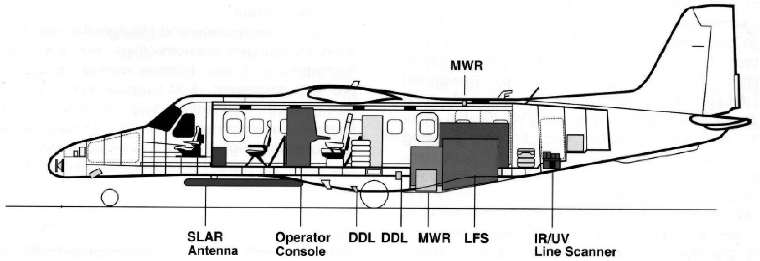
However there is currently no single sensor which can provide the relevant information for oil spill surveillance and disaster management, accordingly a combination of sensors are recommended.. For example, German maritime surveillance uses a combination of UV/IR scanner, SLAR, microwave radiometer (MWR) and laser fluorosensor. Here, the location of the oil spill is identified by SLAR while UV/IR is used for finding the extent of the oil spill, MWR measures oil thickness, and laser fluorosensor is used to classify the oil type (Figure 9). Sweden uses a combination of SLAR, infrared and visible sensors. Many European surveillance systems use satellite sensors. The satellite data from ENVISAT ASAR and RADARSAT-1 is available within one hour of data acquisition. Transport Canada also uses a combination of satellite and airborne sensors for oil spill surveillance with extensive use of RADARSAT-1 data with some imagery from ENVISAT ASAR under the Integrated Satellite Tracking of Oil polluters (ISTOP) program. The Emergency Science and Technology Division (ESTD) of Environment Canada conducts oil spill surveillance in the event of major oil spills. Environment Canada has a combination of sensors including laser fluorosensor (SLEAF), UV, IR and SAR sensors (Brown and Fingas, 2005).
4. Conclusions
Oil spills constitute a serious environmental and socio-economic problem. Oil spill surveillance is an important part of oil spill contingency planning. Current remote sensing sensors have been evaluated in terms of their usefulness for detecting and monitoring oil spills. Laser fluorosensors were found to be the best available sensor for oil spill surveillance as they can detect oil on various backgrounds including ice and the shoreline. However, no single sensor had capability to provide all the information needed for oil spill surveillance. Many European and North American agencies are using a combination of sensors for oil spill monitoring. Advantages and disadvantages of using space-borne sensors versus airborne sensors were discussed. Though using space-borne sensor data is cheap they suffer from poor temporal resolution. Real time remote sensing data is essential for oil spill response so that resources can be immediately directed to sensitive areas for cleaning and containment operations. Recent advances in satellite remote sensing have made them more useful for oil spill detection. However, it is unlikely that they will replace airborne remote sensing for tactical response in the near future.
Acknowledgments
The financial support for this research from GEOIDE (Canadian Geomatics for Informed Decisions) NCE (Networks of Centers of Excellence) and NSERC (Natural Sciences and Engineering Research Council) of Canada is greatly acknowledged.
References
- Babichenko, S.; Dudelzak, A.; Lapimaa, J.; Lisin, A.; Poryvkina, L.; Vorobiev, A. Locating water pollution and shore discharges in coastal zone and inland waters with FLS lidar. EARSeL eProceedings 2006, 5.1, 32–41. [Google Scholar]
- Brekke, C.; Solberg, A. 2005. Oil spill detection by satellite remote sensing. Remote Sensing of Environment 2005, 95, 1–13. [Google Scholar]
- Brown, C.; Fingas, M. Review of Oil Spill Remote Sensing. Spill Science & Technology Bulletin 1997, 4.4, 199–208. [Google Scholar]
- Brown, C.; Fingas, M. New space-borne sensors for oil spill response. In International OIL SPILL Conference.; American Petroleum Institute: Washington DC, 2001a; pp. 911–916. [Google Scholar]
- Brown, C.; Fingas, M. Upcoming Satellites: Potential Applicability to Oil Spill Remote Sensing. Proc. 24th Arctic and Marine Oil Spill Program (AMOP) Technology Seminar, Edmonton, Canada, June 12–14, 2001b; pp. 495–505.
- Brown, C.; Fingas, M.; Hawkins, R. Synthetic Aperture Radar Sensors: Viable for Marine Oil Spill Response? Proc. 26th Arctic and Marine Oil Spill Program (AMOP) Technology Seminar, Victoria, Canada, June 10–12, 2003; pp. 299–310.
- Brown, C.; Fingas, M. Review of the development of laser fluorosensors for oil spill application. Marine Pollution Bulletin 2003a, 47, 477–484. [Google Scholar]
- Brown, C.; Fingas, M. Development of airborne oil thickness measurements. Marine Pollution Bulletin 2003b, 47, 485–492. [Google Scholar]
- Brown, C.; Fingas, M.; Marois, R. Oil spill remote sensing: laser fluorosensor demonstration flights off the east coast of Canada. Proc. 27th Arctic and Marine Oil Spill Program (AMOP) Technology Seminar, Edmonton, Canada, June 6–8, 2004a; pp. 317–334.
- Brown, C.; Fingas, M.; Marois, R.; Fieldhouse, B.; Gamble, R. Remote sensing of water-in-oil emulsions: initial laser fluorosensor studies. Proc. 27th Arctic and Marine Oil Spill Program (AMOP) Tech. Seminar, Edmonton, Canada, Jun. 6–8, 2004b; pp. 295–306.
- Brown, C.; Fingas, M. A review of current global oil spill surveillance, monitoring and remote sensing capabilities. Proc. 28th Arctic and Marine Oil Spill Program (AMOP) Tech. Seminar, Calgary, Canada, Jun. 7–9, 2005; pp. 789–798.
- Brown, C.; Fingas, M.; Monchalin, J.; Neron, C.; Padioleau, C. Airborne measurement of oil slick thickness. Proc. 29th Arctic and Marine Oil Spill Program (AMOP) Tech. Seminar, Vancouver, Canada, Jun. 6–8, 2006a; pp. 911–919.
- Brown, C.; Fingas, M.; Marois, R. Oil spill Remote Sensing flights around Vancouver Island. Proc. 29th Arctic and Marine Oil Spill Program (AMOP) Tech. Seminar, Vancouver, Canada, Jun. 6–8, 2006b; pp. 921–930.
- Fant, J.; Hansen, K. U.S. Coast Guard Laser Fluorosensor Testing. Proc. 29th Arctic and Marine Oil Spill Program (AMOP) Tech. Seminar, Vancouver, Canada, Jun. 6–8, 2006; pp. 951–964.
- Fingas, M.F.; Brown, C.E.; Mullin, J.V. A Comparison of the Utility of Airborne Oil Spill Remote Sensors and Satellite Sensors. Proceedings, Fifth Conference on Remote Sensing for Marine and Coastal Environmentsi, Ann Arbor, MI; 1998; 1, pp. I-171–I-178. [Google Scholar]
- Fingas, M. The Basics of Oil Spill Cleanup; CRC Press LLC: USA, 2001. [Google Scholar]
- Fingas, M.; Brown, C. An update on oil spill remote sensors. Proc. 28th Arctic and Marine Oil Spill Program (AMOP) Tech. Seminar, Calgary, Canada, Jun. 7–9, 2005; pp. 825–860.
- Goodman, R. Overview and Future Trends in Oil Spill Remote Sensing. Spill Science & Technology Bulletin 1994, 1.1, 11–21. [Google Scholar]
- Grüner, K.; Reuter, R.; Smid, H. A New Sensor System for Airborne Measurements of Maritime Pollution and of Hydrographic Parameters. Geojournal 1991, 24.1, 103–117. [Google Scholar]
- Hengstermann, T.; Reuter, R. Lidar fluorosensing of mineral oil spills on the sea surface. Appl. Opt. 1990, 29, 3218–3227. [Google Scholar]
- Hoge, F.E.; Swift, R.N. Oil film thickness measurement using airborne laser induced water Raman backscatter. Applied Optics 1980, 19.19, 3269–3281. [Google Scholar]
- Jones, B. A comparison of visual observations of surface oil with Synthetic Aperture Radar imagery of the Sea Empress oil spill. International Journal of Remote Sensing 2001, 22.9, 1619–1638. [Google Scholar]
- Landgrebe, D.A. Signal theory methods in multispectral remote sensing; John Wiley: USA, 2003. [Google Scholar]
- Lennon, M.; Babichenko, S.; Thomas, N.; Mariette, V.; Mercier, G.; Lisin, A. Detection and Mapping of Oil Slicks in the Sea by Combined Use of Hyperspectral Imagery and Laser Induced Fluorescence. EARSeL eProceedings 2006, 5, 1–9. [Google Scholar]
- Li, J. Spill Management for the Toronto AOC: The City of Toronto Study. Report and factsheet prepared for the Great Lakes Sustainability Fund, Burlington, Ontario, Canada 2002. [Google Scholar]
- Lunel, T. Satellite remote sensing at the SEA EMPRESS spill- a help or potential hindrance. Proc. 19th Arctic and Marine Oil Spill Program (AMOP) Tech. Seminar, Calgary, Canada, Jun. 12–14, 1994; pp. 1221–1236.
- Natural Resources Canada Website. http://ccrs.nrcan.gc.ca/resource/tutor/fundam/chapter5/28_e.php Last accessed on Dec 20, 2007.
- NOAA. USA website (National Oceanic and Atmospheric Administration). http://response.restoration.noaa.gov/. See Topic: Emergency Response, Responding to Oil Spills Last accessed on Dec 20, 2007.
- Olsen, R.; Bugden, P.; Andrade, Y.; Hoyt, P.; Lewis, M.; Edel, H.; Bjerkelund, C. Operational Use of RADARSAT SAR for Marine Monitoring and Surveillance. Proceedings IEEE 95CH35770, IGARSS, Firenze, Italy, July 10-14, 1995; pp. 224–226.
- Plaza, J.; Pérez, R.; Plaza, A.; Martínez, P.; Valencia, D. Mapping oil spills on sea water using spectral mixture analysis of hyperspectral image data. Proc. of SPIE 2001, 5995, 599509–1. [Google Scholar]
- Salem, F.; Kafatos, M. Hyperspectral image analysis for oil spill mitigation. 22nd Asian Conference on Remote Sensing, Singapore; 2001; 1, pp. 748–753. [Google Scholar]
- Salisbury, J.; D'aria, D.; Sabins, F. Thermal Infrared Remote Sensing of Crude Oil Slicks. Remote Sensing of Environment 1993, 45, 225–231. [Google Scholar]
- Samberg, A. Advanced oil pollution detection using an airborne hyperspectral lidar technology. Proceedings of SPIE, the International Society for Optical Engineering 2005, 5791, 308–317. [Google Scholar]
- Simecek-Beatty, D.; Pichel, W. RADARSAT-1 synthetic aperture radar analysis for M/V Selendang Ayu oil spill. Proc. 29th Arctic and Marine Oil Spill Program (AMOP) Tech. Seminar, Vancouver, Canada, Jun. 6–8, 2006; pp. 931–949.
- Trieschmann, O.; Hunsänger, Th.; Barjenbruch, U. A multiple remote sensor system for the aerial surveillance of the north sea and baltic sea. Presented at the Fifth International Airborne Remote Sensing Conference, San Francisco, California, 17- 20 September, 2001; Available on http://www.bafg.de/servlet/is/5863/proceedings.pdf.
- Trieschmann, O.; Hunsnger, T.; Tufte, L.; Barjenbruch, U. Data assimilation of an airborne multiple remote sensor system and of satellite images for the North- and Baltic sea. Proceedings of the SPIE 10th int. symposium on remote sensing, conference remote sensing of the ocean and sea ice; 2003; pp. 51–60. [Google Scholar]
- Wadsworth, A.; Looyen, W. J.; Reuter, R.; Petit, M. Aircraft experiments with vsible and infrared sensors. International Journal of Remote Sensing 1992, 13.6, 1175–1199. [Google Scholar]
- Wismann, V.; Gade, M.; Alpers, W.; Hühnerfuss, H. Radar signatures of marine mineral oil spills measured by an airborne multi-frequency radar. International Journal of Remote Sensing 1998, 19, 3607–3623. [Google Scholar]
Figure 1.
Sea birds affected by the Exxon Valdez oil spill (Photo courtesy of the Exxon Valdez Oil Spill Trustee Council).
Figure 1.
Sea birds affected by the Exxon Valdez oil spill (Photo courtesy of the Exxon Valdez Oil Spill Trustee Council).

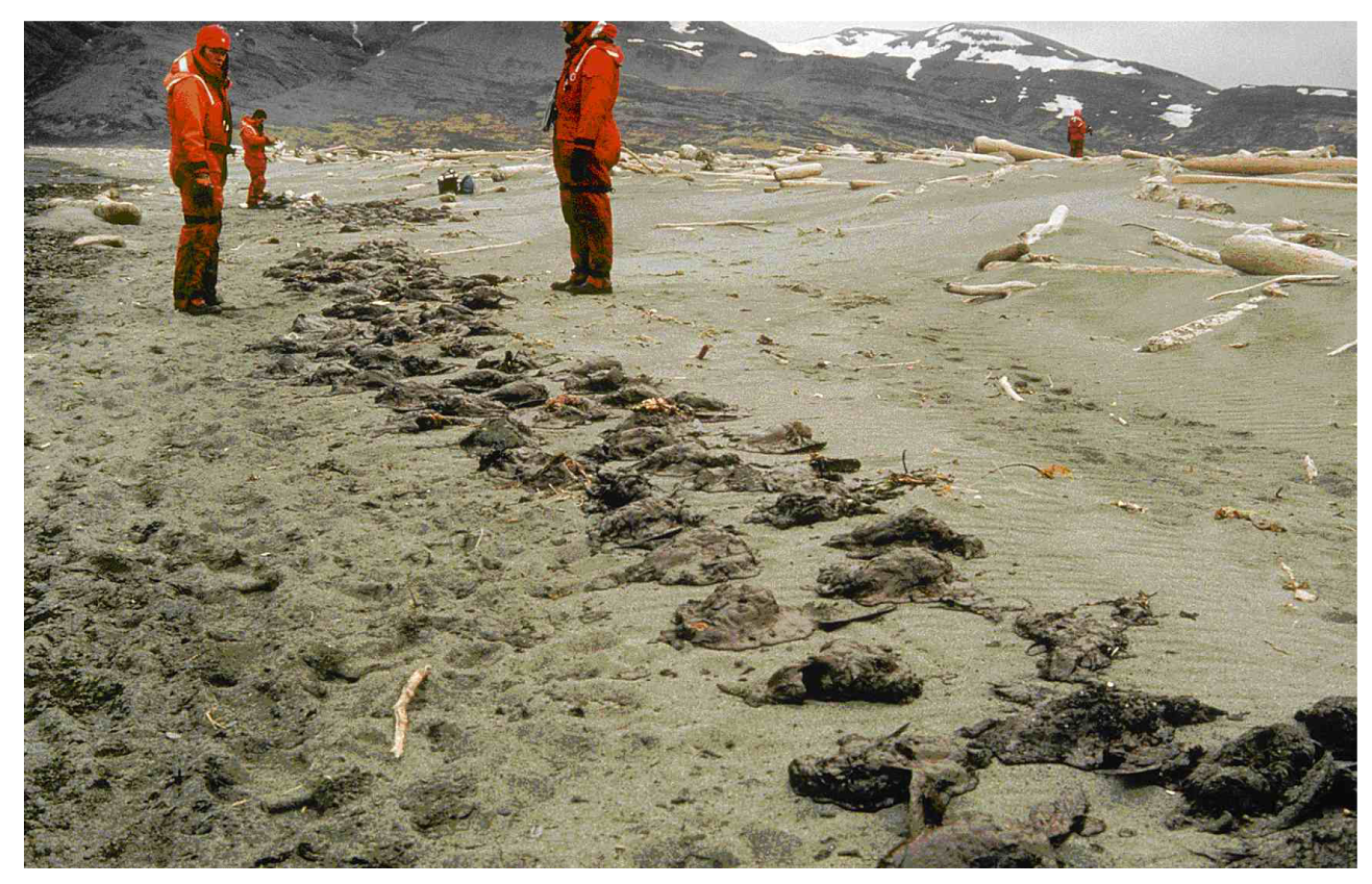
Figure 2.
Image of Exxon Valdez oil spill captured by a sensor in the visible range (Source: NOAA, 2007).
Figure 2.
Image of Exxon Valdez oil spill captured by a sensor in the visible range (Source: NOAA, 2007).
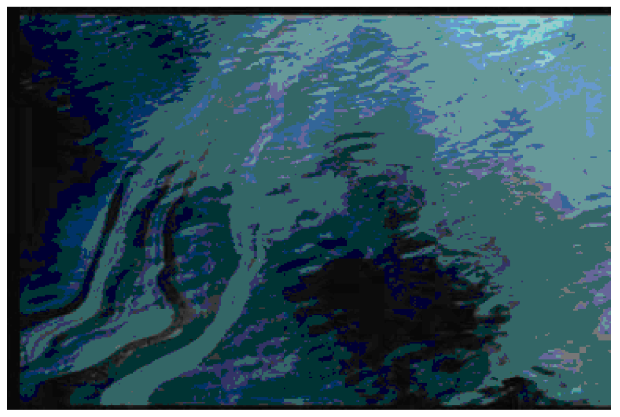
Figure 3.
SAR image (RADARSAT-1) of oil spill in Strait of Malacca.
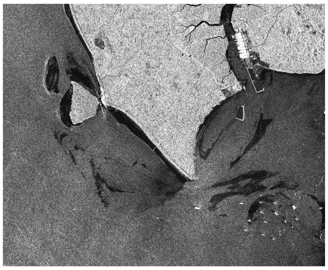
Figure 4.
Fluorescence spectra of different oils (Source: ESTD, Environment Canada).
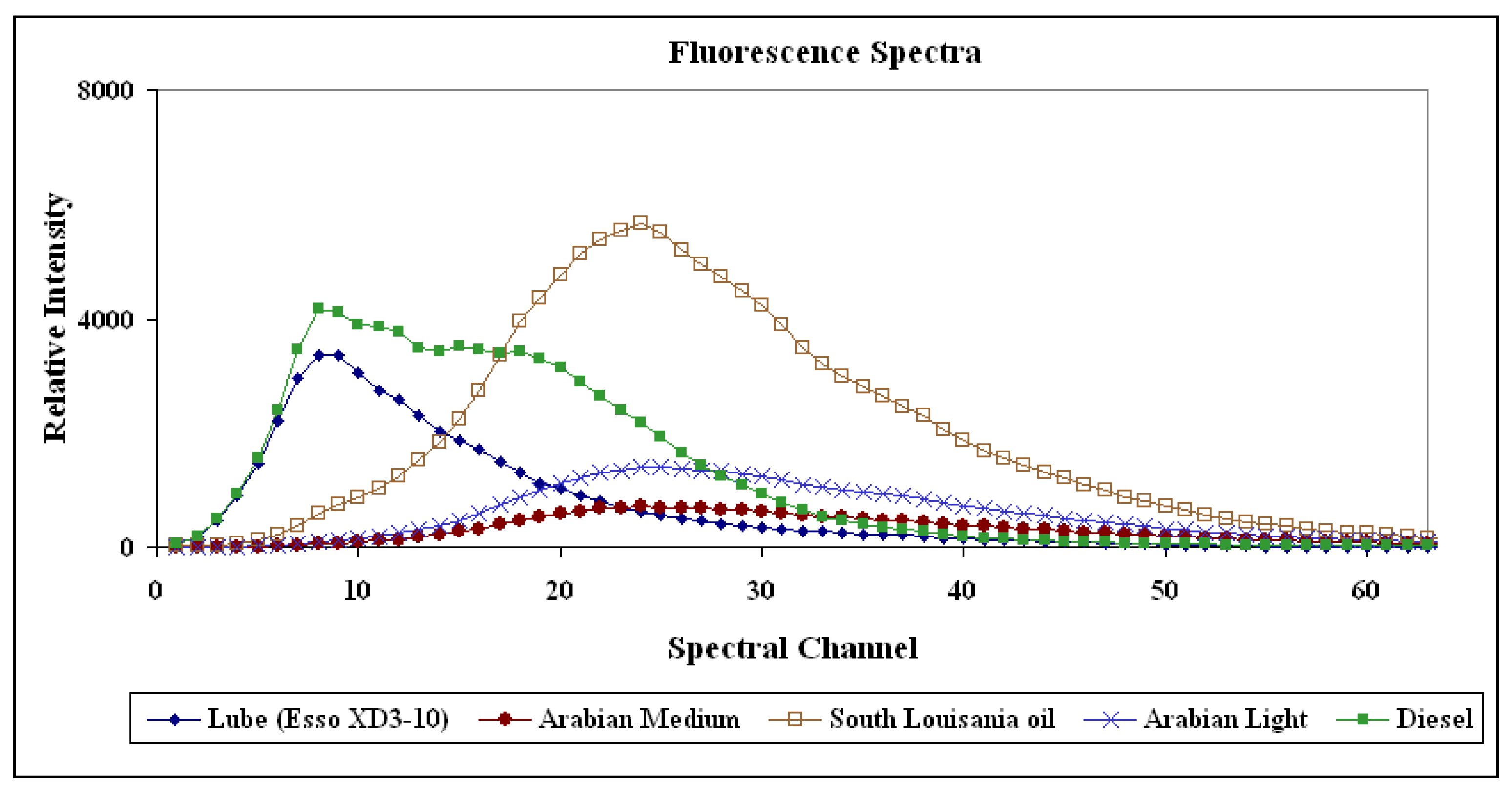
Figure 5.
Fluorescence spectra of natural water for excitation wavelength as 308 nm (Adapted from Grüner, 1991).
Figure 5.
Fluorescence spectra of natural water for excitation wavelength as 308 nm (Adapted from Grüner, 1991).
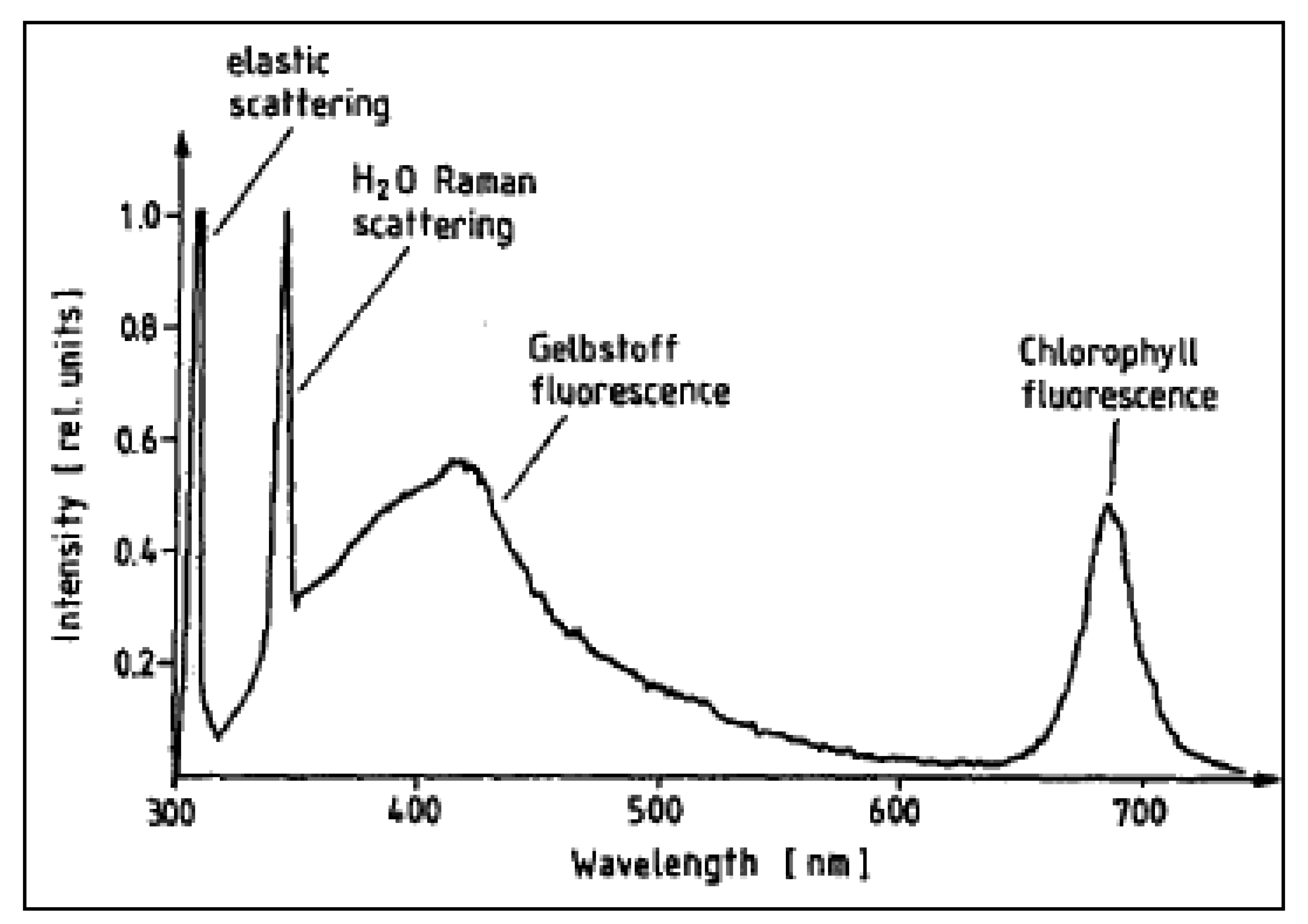
Figure 6.
Laser Induced Fluorescence (LIF) spectrum for oil slick and sea water (Adapted from Hoge and Swift, 1980).
Figure 6.
Laser Induced Fluorescence (LIF) spectrum for oil slick and sea water (Adapted from Hoge and Swift, 1980).
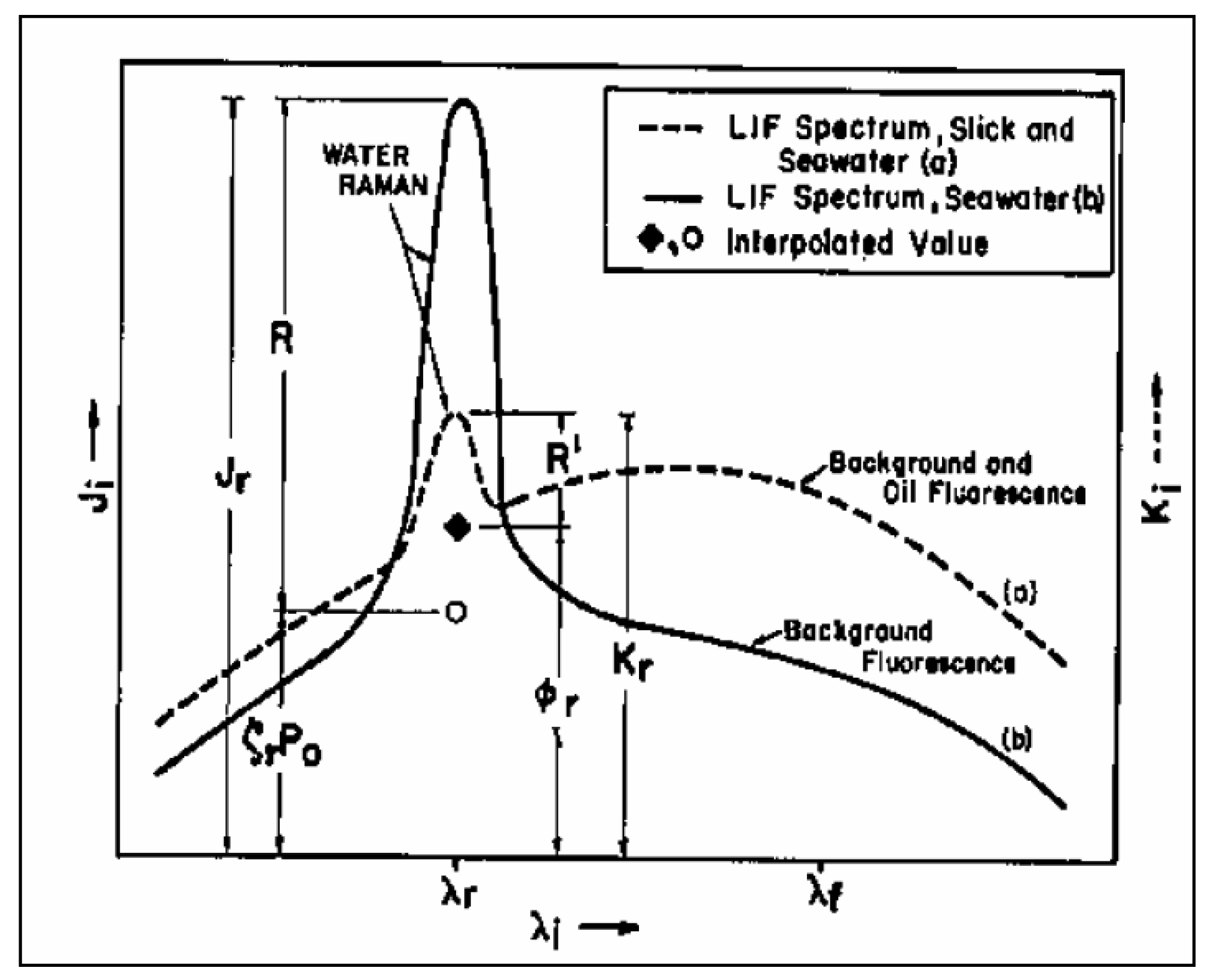
Figure 7.
Laser footprints on the ground of FLS-LIDAR (Adapted from Babichenko et al., 2006).
Figure 7.
Laser footprints on the ground of FLS-LIDAR (Adapted from Babichenko et al., 2006).

Figure 8.
Processed single flight line laser fluorosensor data for an oil spill where spikes indicate oil slick thickness (Source: Laser Diagnostic Instruments AS).
Figure 8.
Processed single flight line laser fluorosensor data for an oil spill where spikes indicate oil slick thickness (Source: Laser Diagnostic Instruments AS).

Figure 9.
Profile of the German (Do228 LM1) aircraft with measuring equipment (Adapted from Trieschmann et al., 2001).
Figure 9.
Profile of the German (Do228 LM1) aircraft with measuring equipment (Adapted from Trieschmann et al., 2001).

| Oil Appearance | Approximate Film Thickness (μm) |
|---|---|
| Silvery sheen | 0.05 |
| Rainbow sheen | 0.15 |
| Reddish-brown sheen | 0.50 |
| Brownish | 2.00 |
| Dark | 10.00 |
| Dark Brown | 50.00 |
Table 2.
Remote sensing bands and related instruments used for oil spill detection (Adapted from Goodman, 1994).
| Band | Wavelength | Type of Instruments |
|---|---|---|
| Radar | 1-30 cm | SLAR/SAR |
| Passive microwave | 2-8 mm | Radiometers |
| Thermal infrared (TIR) | 8-14 μm | Video cameras and line scanners |
| Mid-band infrared (MIR) | 3-5 μm | Video cameras and line scanners |
| Near infrared | 1-3 μm | Film and video cameras |
| Visual | 350-750 nm | Film, video cameras and spectrometers |
| Ultraviolet | 250-350 nm | Film, Video cameras and line scanners |
Table 3.
Requirements for oil spill detection (Adapted from Brown et al., 2003).
| Minimum Resolution Requirements | Maximum Time During Which Useful Data Can Be Collected (Hours) | ||
|---|---|---|---|
| Task | Large Spill | Small Spill | |
| Detect oil on water | 6 | 2 | 1 |
| Map oil on water | 10 | 2 | 12 |
| Map oil on land/shore | 1 | 0.5 | 12 |
| Tactical water cleanup | 1 | 2 | 1 |
| Tactical support land/shore | 1 | 0.5 | 1 |
| Thickness/volume | 1 | 0.5 | 1 |
| Legal and prosecution | 3 | 1 | 6 |
| General documentation | 3 | 1 | 1 |
| Long-range surveillance | 10 | 2 | 1 |
| Spatial Resolution (m) | Swath Width (km) | Over-pass Frequency (days) | Full-earth Repeat Cycle (days) | Process Time: Typical | ||||
|---|---|---|---|---|---|---|---|---|
| Minimum | Range | |||||||
| Radar | Space-borne | ERS-2 | 30 | 100/150 | 3 | 35 | <2 hours | |
| RADARSAT-1 | 9 | 9-100 | 50-500 | 2 | 7/17 | <2 hours | ||
| Airborne | Typical SLAR | 10 | 10-50 | 10-40 | As Required | realtime | ||
| Typical SAR | 1-3 | 1-10 | 10-40 | As Required | realtime | |||
| Optical | Space-borne | Landsat TM | 15 | 15-120 | 185 | 16 | 3 days | |
| SPOT | 10 | 60/85 | 26 | 3 days | ||||
| Airborne | Video Camera | <1 | Altitude Dependent | Altitude Dependent | As Required | realtime | ||
| Still Camera | <0.1 | Altitude Dependent | Altitude Dependent | As Required | 1 day | |||
| Typical Scanner | <1 | Altitude Dependent | Altitude Dependent | As Required | realtime | |||
| Visible | Infrared | UV | Radar | Microwave Radiometer | Laser Fluorosensor | Laser-acoustic oil thickness sensor | |
|---|---|---|---|---|---|---|---|
| Cost (K$) | 0.25-20 | 1-200 | 100-300 | 1200-8000 | 400-2000 | 300-2000 | Expensive |
| False Detection | Sea weed, darker shoreline | Sea weed, shoreline | wind sheen, sun glint and sea weed | Many interferences | No significant interferences | Can identify oil on any background | Low |
| Thickness Information | No | Relative thickness | No | Relative thickness under some conditions | 50 μm-few mm | < 20 μm | Measures Absolute thickness |
| Spatial Resolution | High | High | High | High | Low | High, line profile | High, line profile |
| Weather Requirement | Cloudless, Clear | Absence of cloud and heavy fog | Requires clear atmosphere | All weather. Detection dependent upon wind speed | All weather except heavy rain | Can not penetrate cloud and fog | Can no penetrate cloud and fog |
| 24 hour operation | No | Yes | No | Yes | Yes | Yes | Yes |
| Horizontal Range (300m Altitude) | Medium | ±250m | ±250m | ±30 km | ±250m | ±75m | Small |
| Dedicated Aircraft | No | No | No | Yes | Yes | Yes | Yes |
| Oil Classification | No | No | No | No | No | Yes | No |
© 2008 by MDPI Reproduction is permitted for noncommercial purposes.
Share and Cite
MDPI and ACS Style
Jha, M.N.; Levy, J.; Gao, Y. Advances in Remote Sensing for Oil Spill Disaster Management: State-of-the-Art Sensors Technology for Oil Spill Surveillance. Sensors 2008, 8, 236-255. https://doi.org/10.3390/s8010236
AMA Style
Jha MN, Levy J, Gao Y. Advances in Remote Sensing for Oil Spill Disaster Management: State-of-the-Art Sensors Technology for Oil Spill Surveillance. Sensors. 2008; 8(1):236-255. https://doi.org/10.3390/s8010236
Chicago/Turabian StyleJha, Maya Nand, Jason Levy, and Yang Gao. 2008. "Advances in Remote Sensing for Oil Spill Disaster Management: State-of-the-Art Sensors Technology for Oil Spill Surveillance" Sensors 8, no. 1: 236-255. https://doi.org/10.3390/s8010236