Effects of Orbit and Pointing Geometry of a Spaceborne Formation for Monostatic-Bistatic Radargrammetry on Terrain Elevation Measurement Accuracy


Abstract
:1. Introduction
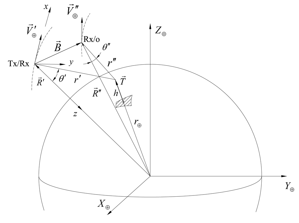
2. Monostatic-Bistatic Geometry for Stereo-Radargrammetric Reconstruction
- -
- the bistatic image quality in terms of resolutions, ambiguities, signal-to-noise-ratio (SNR) is greatly affected by the monostatic-bistatic configurations, even before stereo reconstruction, therefore the effect of the acquisition geometry on bistatic image parameters must be accounted for when selecting the optimum configuration for radargrammetric DEM generation;
- -
- when a monostatic image and a bistatic one are adopted to form a stereoscopic pair, new relations are needed to define target height as a function of the peculiar parameters of monostatic-bistatic surveying geometry [23]. Namely, the models of classical stereo-radargrammetry can be specialized to the monostatic/bistatic configuration, but also new models can be developed [17, 24].
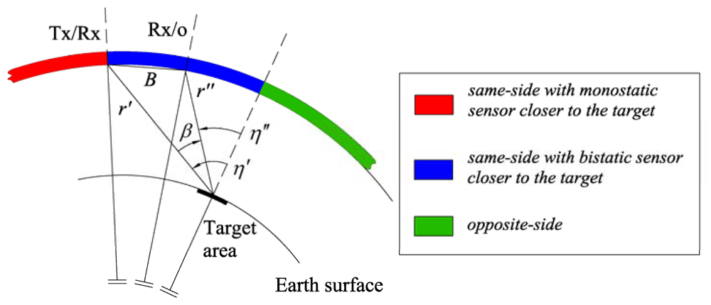
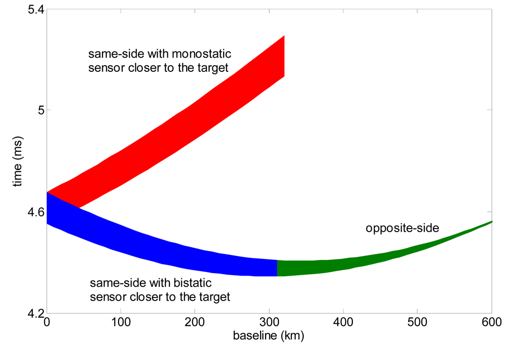
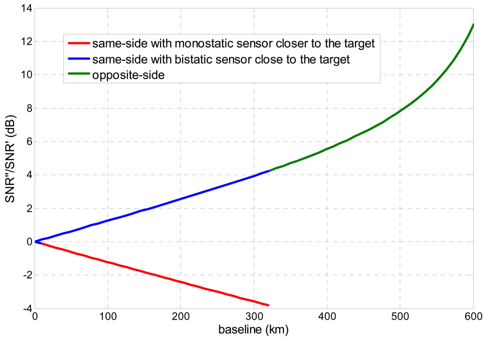
2.1. Monostatic-Bistatic Observation Strategies
- -
- same-side with monostatic sensor closer to the target;
- -
- same-side with bistatic satellite closer to the target;
- -
- opposite-side.
2.2. Methods for Monostatic-Bistatic DEM Generation
2.2.1. Projection of Bistatic Parameters
2.2.2. Bistatic Rigorous SAR Stereo Problem
2.2.3. Hybrid
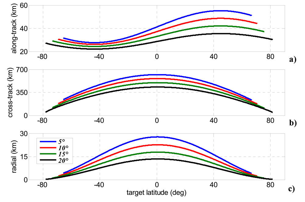
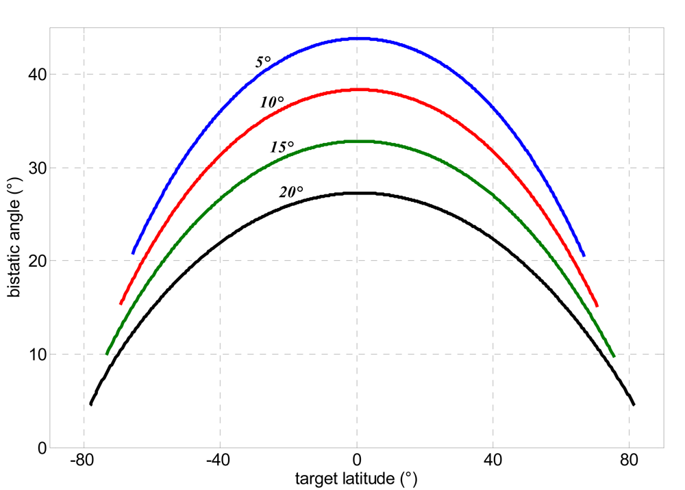
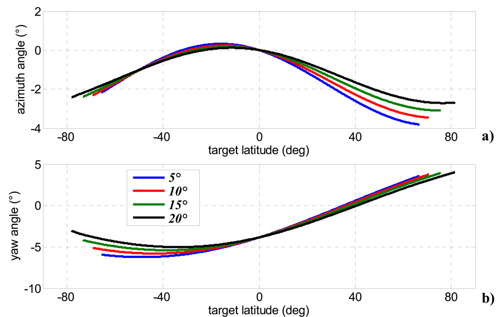
3. Mission Design
- -
- parallel orbits, to take advantage of stereo effect;
- -
- bistatic angle larger than 5-10°;
- -
- same-side stereo configuration, to avoid bistatic slant range ambiguities;
- -
- bistatic sensor closer to the target thus limiting too large off-nadir angles for the bistatic receiver and benefiting by stronger echoes.
- -
- monostatic SAR elevation steering counteracts cross-track separation;
- -
- bistatic SAR azimuth elevation steering (<4°) avoids along-track separations;
- -
- an ad hoc designed yaw-steering manoeuvre for the bistatic satellite can be used to overcome swaths relative rotations.
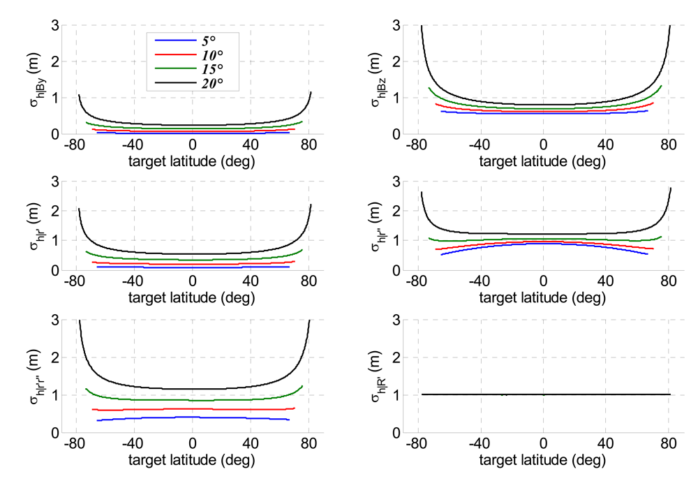
4. Error Budget of Height Estimation Accuracy
4.1. Error Sources and Sensitivities
4.2. Height Estimation Accuracy
5. Conclusions
References and Notes
- Krieger, G.; Moreira, A. Spaceborne bi- and Multistatic SAR: Potential and Challenges. Proc. Inst. Electr. Eng.-Radar, Sonar Navig. 2006, 3, 184–198. [Google Scholar]
- Renga, A.; Moccia, A.; D'Errico, M.; Dellepiane, S.; Angiati, E.; Vernazza, G.; Lombardo, P.; Colone, F.; Sedehi, M.; Cristallini, D.; Pignataro, S.; Rioli, Q.; Milillo, G.; Bruno, C.; Di Giorgio, F.; Labriola, M. From the Expected Scientific Applications to the Functional Specifications, Products and Performance of the SABRINA Missions. IEEE, Radar Conference, Rome, Italy, May 26-30, 2008; pp. 1117–1122.
- Moccia, A.; Salzillo, G.; D'Errico, M.; Rufino, G.; Alberti, G. Performance of spaceborne bistatic synthetic aperture radar. IEEE Trans. Aerospace Electronic Syst. 2005, 41, 1383–1395. [Google Scholar]
- Caves, R.; Luscombe, A.P.; Lee, P.F.; James, K. Topographic Performance Evaluation of the RADARSAT 2/3 Tandem Mission. Proc. Int. Geoscience and Remote Sensing Symposium, IGARSS'02, Toronto, Canada, June 2002; 2, pp. 961–963.
- Massonnet, D. Capabilities and Limitations of the Interferometric Cartwheel. IEEE Trans. Geosci. Remote Sens. 2001, 39, 506–520. [Google Scholar]
- Krieger, G.; Moreira, A.; Fiedler, H.; Hajnsek, I.; Werner, M.; Younis, M.; Zink, M. TanDEM-X: A Satellite Formation for High-Resolution SAR Interferometry. IEEE Trans. Geosci. Remote Sens. 2007, 45, 3317–3341. [Google Scholar]
- Rosen, A.; Hensley, S.; Joughin, I.R.; Li, F.K.; Madsen, S.N.; Rodriguez, E.; Goldstein, R.M. Synthetic Aperture Radar Interferometry. Proceedings of the IEEE 2000, 88, 333–382. [Google Scholar]
- Gelautz, M.; Paillou, P.; Chen, C.; Zebker, H. Radar Stereo- and Interferometry-derived Digital Elevation Models: Comparison and Combination Using Radarsat and ERS-2 Imagery. Int. J. Remote Sens. 2003, 24, 5243–5264. [Google Scholar]
- Toutin, T.; Gray, A.L. State-of-the-art of Extraction of Elevation Data Using Satellite SAR Data. ISPRS J. Photogramm. Remote Sens. 2000, 55, 13–33. [Google Scholar]
- Leberl, F. Radargrammetric Image Processing; Artech House Inc: Norwood, MA, 1990; Ch. 12–13. [Google Scholar]
- Zebker, H.A.; Villasenor, J. Decorrelation in Interferometric Radar Echoes. IEEE Trans. Geosci. Remote Sens. 1992, 30, 950–959. [Google Scholar]
- Rodriguez, E.; Martin, J.M. Theory and Design of Interferometric Synthetic Aperture Radars. IEE Proc. -F 1992, 139, 147–159. [Google Scholar]
- Toutin, T. Error Tracking of Radargrammetric DEM from RADARSAT Images. IEEE Trans. Geosci. Remote Sens. 1999, 37, 2227–2238. [Google Scholar]
- Toutin, T. Impact of Terrain Slope and Aspect on Radargrammetric DEM Accuracy. ISPRS J. Photogramm. Remote Sens. 2000, 57, 228–240. [Google Scholar]
- Leberl, F.; Domik, G.; Raggam, J.; Kobrik, M. Radar Stereomapping Techniques and Application to SIR-B Images of Mt. Shasta. IEEE Trans. Geosci. Remote Sens. 1986, GE-24, 473–481. [Google Scholar]
- Leberl, F.; Domik, G.; Raggam, J.; Cimino, J.B.; Kobrick, M. Multiple Incidence Angle SIR-B Experiment over Argentina: Stereo-Radargrammetric Analysis. IEEE Trans. Geosci. Remote Sens. 1986, 24, 482–491. [Google Scholar]
- Renga, A.; Moccia, A. Performance of Stereo Radargrammetric Methods Applied to Spaceborne Monostatic-Bistatic Synthetic Aperture Radar. IEEE Trans. Geosci. Remote Sens. 2008. [Google Scholar] [CrossRef]
- Caltagirone, F.; Spera, P.; Gallon, A.; Manoni, G.; Bianchi, L. COSMO-SkyMed: A Dual Use Earth Observation Constellation. Proc. of the 2nd International Workshop on Satellite Constellation and Formation Flying, Haifa, Israel, February 2001; pp. 87–94.
- Battazza, F.; Coletta, A.; Covello, F.; Lopinto, E.; Pietranera, L.; Valentini, G.; Zoffoli, A. COSMO-SkyMed Mission Status. 59th International Astronautical Congress, Glasgow, Scotland, October 2008.
- Caltagirone, F.; Capuzi, A.; Coletta, A.; Galeazzi, C.; Lopinto, E.; Moccia, A. SABRINA: the Italian Mission for Endowing COSMO-SkyMed with Bistatic and Interferometric Capabilities. Proc. of the 6th European Conference on Synthetic Aperture Radar, Dresden, Germany, May 16-18, 2006.
- Lee, H.; Morgan, J.V.; Warner, M.R. Radargrammetry of Opposite-Side Stereo Magellan Synthetic Aperture Radar on Venus. Proc. of Geoscience and Remote Sensing Symposium IGARSS'03, Vigo, Spain, June 30-July 03, 2003; 1, pp. 182–184.
- Sylvander, S.; Cousson, D.; Gigord, P. Etude des Performances Geometriques de Radarsat. Bull. Soc. Franç. Photogramm. Teledetection 1997, 148, 57–65. [Google Scholar]
- Moccia, A. Fundamentals of Bistatic Synthetic Aperture Radar. In Bistatic Radar: Emerging Technology; Cherniakov, M., Ed.; John Wiley & Sons: Chichester, U.K., 2008. [Google Scholar]
- Rigling, D.; Moses, R.L. Three-Dimensional Surface Reconstruction from Multistatic SAR Images. IEEE Trans. Image Process. 2005, 14, 1159–1171. [Google Scholar]
- Willis, N.J.; Griffiths, N.D. Advances in Bistatic Radar; SciTech Publishing: Raleigh, NC, 2007; ch.1,10. [Google Scholar]
- Cardillo, G.P. On the Use of Gradient to Determine Bistatic SAR Resolution. Antennas and Propagation Society International Symposium, Dallas, Texas, May 1990; 2, pp. 1032–1035.
- Zeng, T.; Cherniakov, M.; Long, T. Generalized Approach to Resolution Analysis in BSAR. IEEE Trans. Aerospace .Electron. Syst. 2005, 41, 461–474. [Google Scholar]
- Curlander, J.C.; McDonough, R.N. Synthetic Aperture Radar Systems and Signal Processing; John Wiley & Sons: Chichester, England, 1991; pp. 297–305. [Google Scholar]
- Chen, P.; Dowman, I. J. A Weighted Least Squares Solution for Space Intersection of Spaceborne Stereo SAR Data. IEEE Trans. Geosci. Remote Sens. 2001, 39, 233–240. [Google Scholar]
- Sohn, G.H.; Song, Y.S.; Kim, G.H. Radargrammetry for DEM Generation Using Minimal Control Points. Proc of Geoscience and Remote Sensing Symposium, IGARSS'05, Korea, July 25-29, 2005; 2, pp. 1162–1164.
- Moccia, A.; Chiacchio, N.; Capone, A. Spaceborne Bistatic Synthetic Aperture Radar for Remote Sensing Applications. Int. J. Remote Sens. 2000, 21, 3395–3414. [Google Scholar]
- Moccia, A.; D'Errico, M. Bistatic SAR for Earth Observation. In Bistatic Radar: Emerging Technology; Cherniakov, M., Ed.; John Wiley & Sons: Chichester, England, 2008. [Google Scholar]
- D'Errico, M.; Fasano, G. Design of Interferometric and Bistatic Mission Phases of COSMO-SkyMed Constellation. Acta Astronaut. 2008, 62, 97–111. [Google Scholar]
- Brooks, D. R. An Introduction to Orbit Dynamics and Its Application to Satellite-Based Earth Monitoring Missions. In NASA Reference Publication 1009; NTIS: Springfield, VA, 1977. [Google Scholar]
- D'Errico, M.; Moccia, A. Attitude and Antenna Pointing Design of Bistatic Radar Formations. IEEE Trans. Aerospace .Electron. Syst. 2003, 39, 949–960. [Google Scholar]
- Serva, S.; Colone, F.; Lombardo, P. A Study for a Space-Based Passive Multi-Channel SAR. 2007 IEEE Aerospace Conference, Big Sky, Montana, USA, IEEEAC paper #1185. March 3-10, 2007.
- Krieger, G.; Moreira, A. Spaceborne Interferometric and Multistatic SAR Systems. In Bistatic Radar: Emerging Technology; Cherniakov, M., Ed.; John Wiley & Sons: Chichester, England, 2008. [Google Scholar]
- Farrell, J.; Barth, M. The Global Positioning System and Inertial Navigation; McGraw-Hill: New York, 1999. [Google Scholar]
- Serrano, L.; Kim, D.; Langley, R.B.; Itani, K.; Ueno, M. A GPS Velocity Sensor: How Accurate Can It Be? - A First Look. In ION NTM 2004; San Diego, January 26-28 2004. [Google Scholar]
- [Online]. Available: http://www.e-geos.it/docs/COSMO%20User%20Guide.pdf.
- [Online]. Available: http://earth-info.nga.mil/publications/specs.
- Montenbruck, O.; Ramos-Bosch, P. Precision Real-Time Navigation of LEO Satellites Using Global Positioning System Measurements. GPS Solutions 2008, 12, 187–198. [Google Scholar]
- Kroes, R. Precise Relative Positioning of Formation Flying Spacecraft Using GPS. Ph.D Thesis, Publications on Geodesy, 61, Delft University, Delft, The Netherlands, 2006. [Google Scholar]
- Busse, F. Precise Formation-State Estimation in Low Earth Orbit Using Carrier Differential GPS. Ph.D. Thesis, Stanford University, Dept. of Aeronautics and Astronautics, Stanford University, Palo Alto, CA, 2003. [Google Scholar]
- Renga, A.; Grassi, M. Precise Relative Navigation for Highly Variable Baselines Using Carrier-Based Differential GPS. 59th International Astronautical Congress, Glasgow, Scotland, October 2008.


| Semimajor axis (km) | 6,997.9 |
| Inclination (°) | 97.87 |
| Eccentricity | 0.0018 |
| Argument of perigee (°) | 90 |
| Bistatic off-nadir angle | RAAN difference | Mean anomaly difference | Covered latitudes |
|---|---|---|---|
| 5° | 5.14° | 1.04° | [-65.7°, 66.8°] |
| 10° | 4.64° | 0.942° | [-69.3°, 70.7°] |
| 15° | 4.12° | 0.837° | [-73.8°, 75.6°] |
| 20° | 3.58° | 0.792° | [-78.1°, 81.5°] |
| Method | Functional Model |
|---|---|
| Projection of Bistatic Parameters | |
| Bistatic rigorous SAR stereo problem | |
| Hybrid | |
© 2009 by the authors; Department Of Aerospace Engineering, University of Naples Federico II, Naples, Italy. This article is an open access article distributed under the terms and conditions of the Creative Commons Attribution license (http://creativecommons.org/licenses/by/3.0/).
Share and Cite
Renga, A.; Moccia, A. Effects of Orbit and Pointing Geometry of a Spaceborne Formation for Monostatic-Bistatic Radargrammetry on Terrain Elevation Measurement Accuracy. Sensors 2009, 9, 175-195. https://doi.org/10.3390/s90100175
Renga A, Moccia A. Effects of Orbit and Pointing Geometry of a Spaceborne Formation for Monostatic-Bistatic Radargrammetry on Terrain Elevation Measurement Accuracy. Sensors. 2009; 9(1):175-195. https://doi.org/10.3390/s90100175
Chicago/Turabian StyleRenga, Alfredo, and Antonio Moccia. 2009. "Effects of Orbit and Pointing Geometry of a Spaceborne Formation for Monostatic-Bistatic Radargrammetry on Terrain Elevation Measurement Accuracy" Sensors 9, no. 1: 175-195. https://doi.org/10.3390/s90100175