Environmental Remediation and Conversion of Carbon Dioxide (CO2) into Useful Green Products by Accelerated Carbonation Technology

Abstract
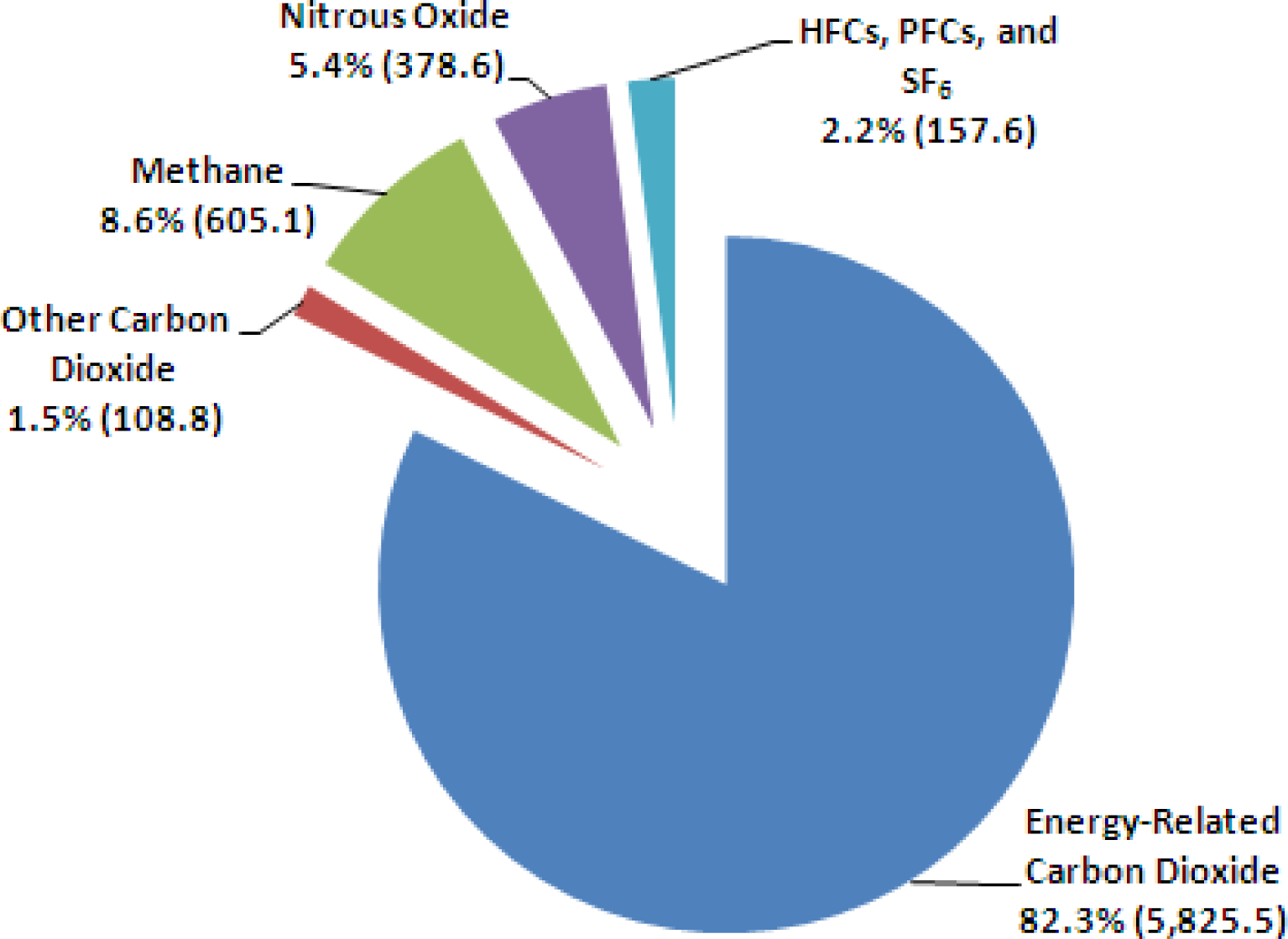
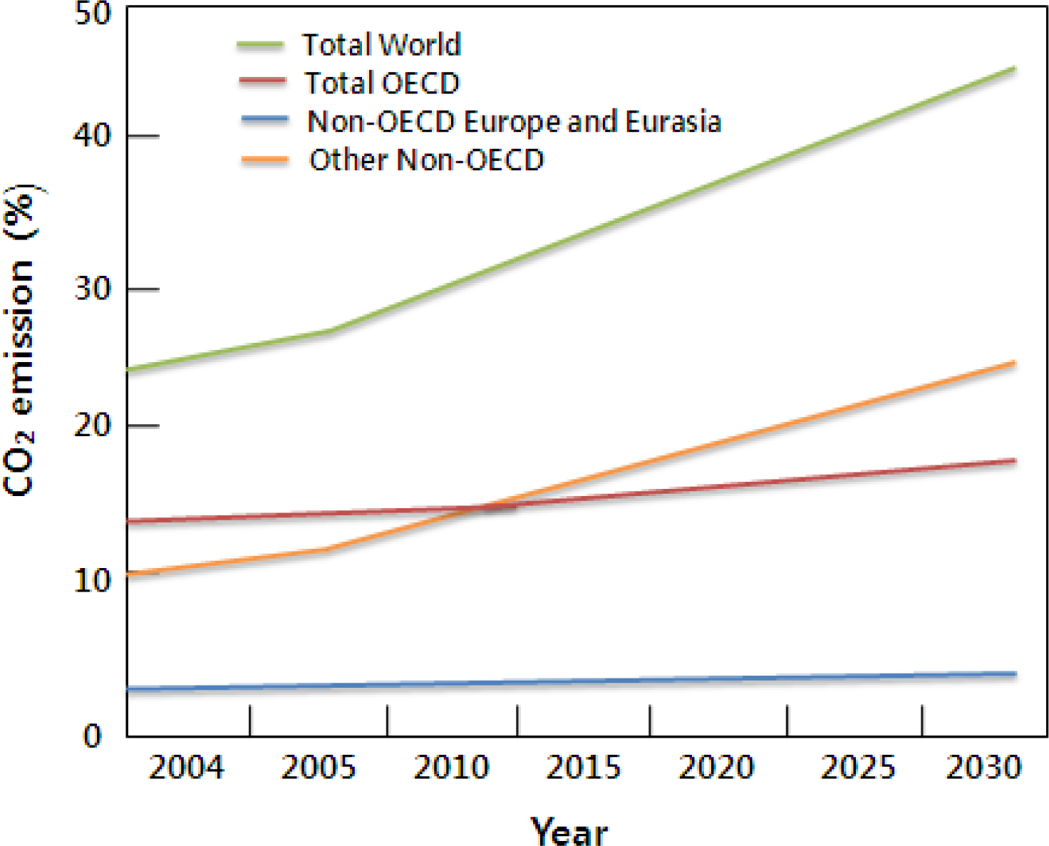
:1. Introduction
2. Carbonation Mechanism and Process
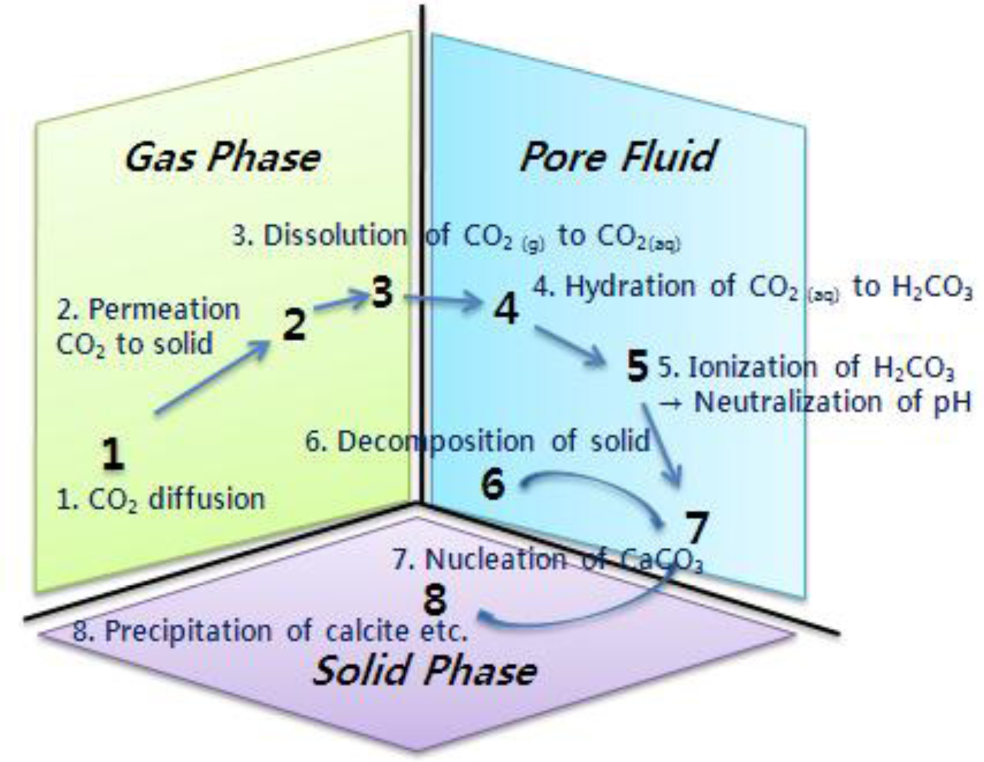
2.1. Carbonation Mechanism
2.2. General Carbonation Processes
2.2.1. Natural carbonation
2.2.2. Accelerated carbonation
2.3. Mineral Carbonation Applying the Accelerated Carbonation
3. Applications of Accelerated Carbonation in the Environmental Industry and Useful Products
3.1. Waste Treatment by Accelerated Carbonation
3.1.1. Municipal solid waste incineration (MSWI) ash
Cases of other researchers
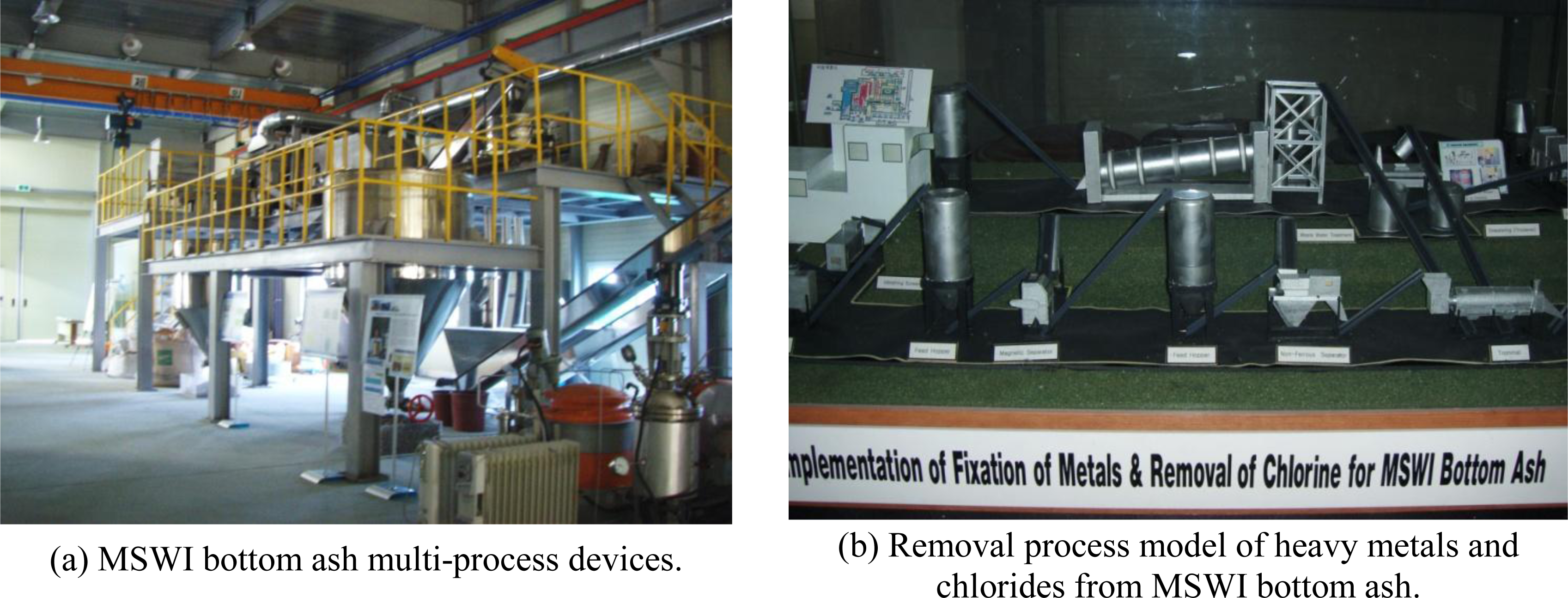
A case from our research group (Combustion Ash Multi-Processing Lab in KIGAM, South Korea)
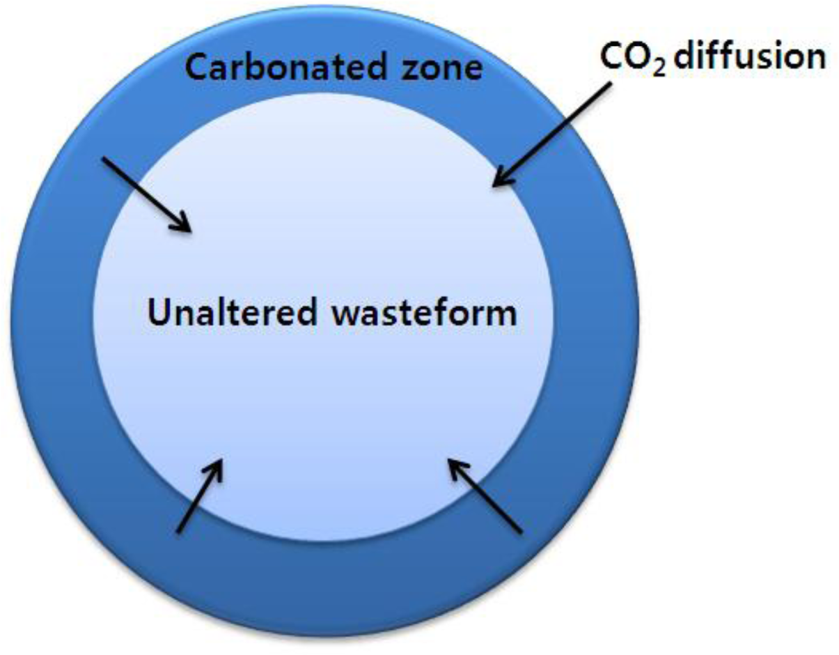
1. Carbonation of heavy metals
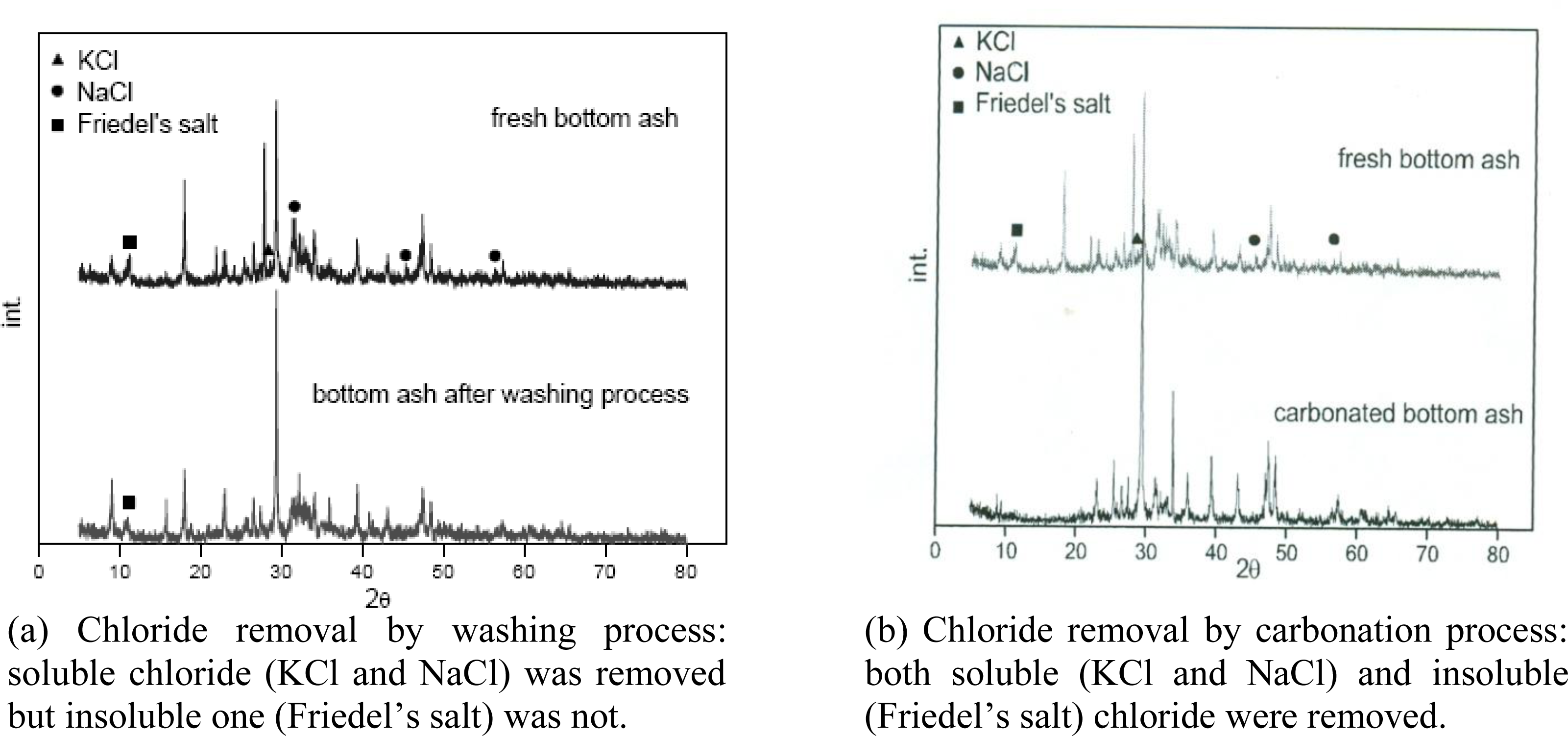
2. Carbonation of soluble (KCl and NaCl) and insoluble chlorides (Friedel’s salt)
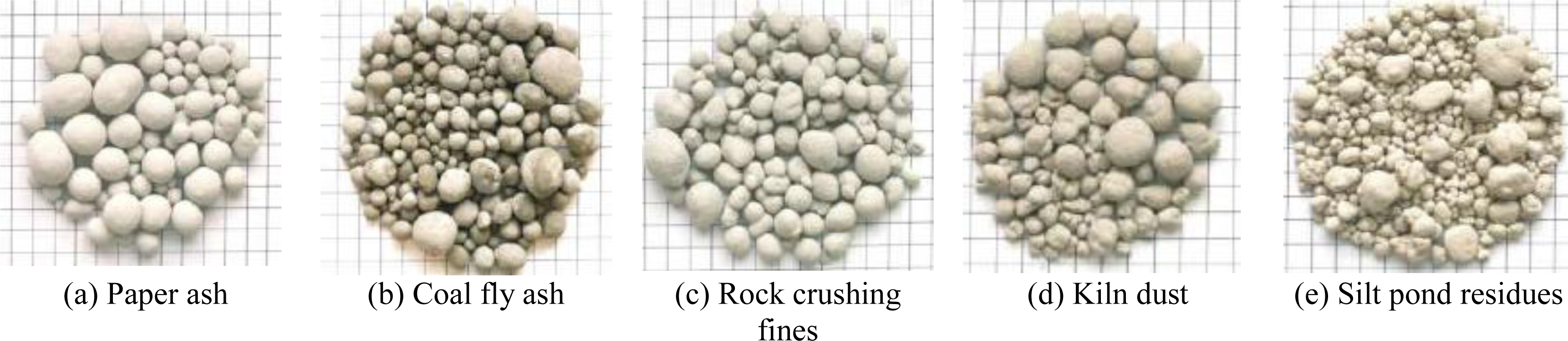
3. Conversion of MSWI bottom ash to cement-based material
3.1.2. Alkaline paper mill waste
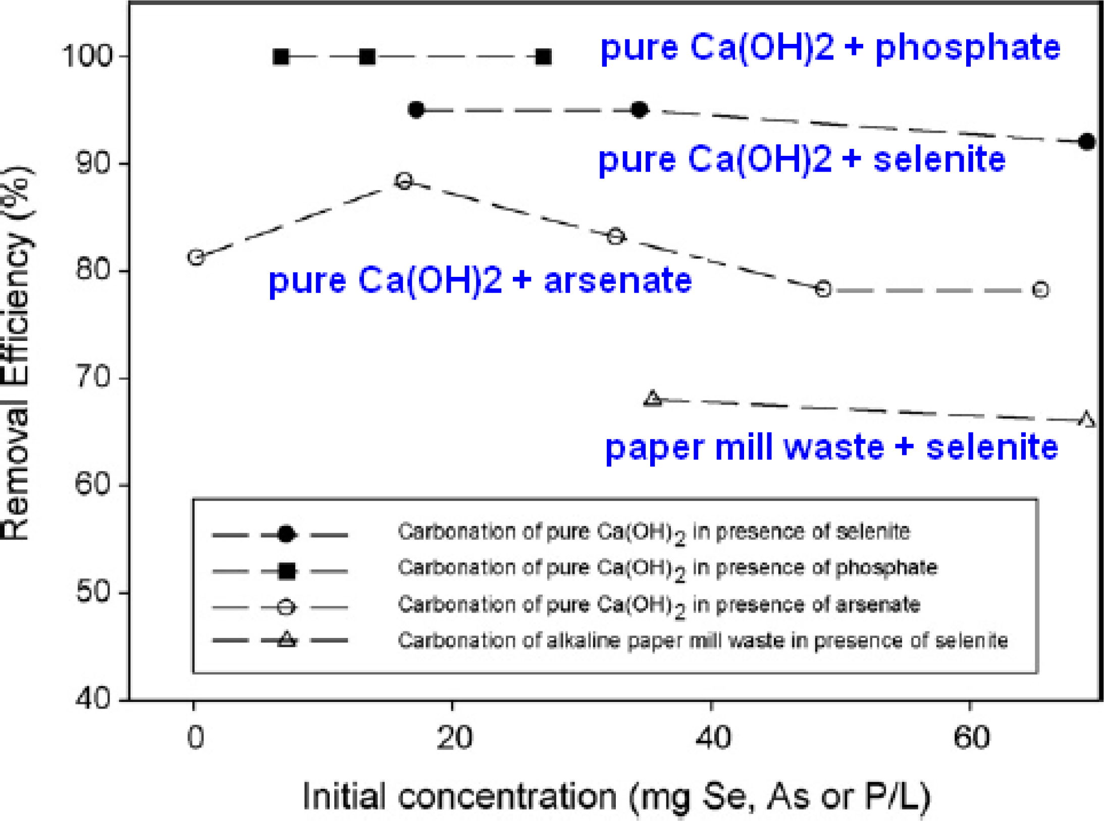
3.2. Wastewater Treatment by Accelerated Carbonation
3.3. Soil Treatment by Accelerated Carbonation
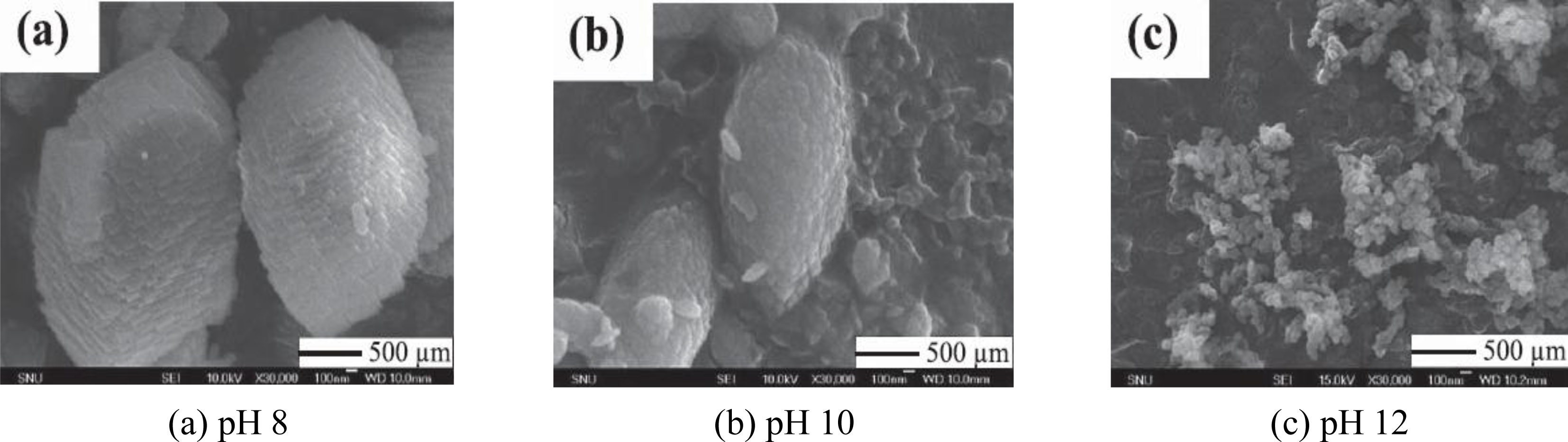
3.4. Synthesis of Precipitated Calcium Carbonate (PCC) by Accelerated Carbonation
Cases of other researchers
A case from our research group (Eco-PCC Lab in KIGAM, South Korea)
4. Quantitative Evaluation of Captured CO2 in Carbonated Products
Previous studies on thermo-gravimetric (TG) analysis of CaCO3
TG analysis of carbonated products by our research group (KIGAM, South Korea)
5. Advanced Applications of Carbon Captured Products
5.1. Application to the Restoration of Shoreline Environments
A case from Japan (by JFE Steel Corporation)
5.2. Application of PCC to the Recycled Paper Industry
A case from the United States (by the US Department of Energy)
A case from South Korea (Eco-PCC Lab, KIGAM)
6. Conclusions
Acknowledgments
References
- United States Environmental Protection Agency. Opportunities to Reduce Greenhouse Gas Emissions through Materials and Land Management Practices; Office of solid waste and emergency response (RPA): Washington, DC, USA, September 2009.
- EIA. Emission of Greenhouse Gases in the United States 2006; Energy Information Administration: Washington, DC, USA, November 2007. [Google Scholar]
- EIA. International Energy Outlook 2007; Energy Information Administration: Washington, DC, USA, May 2007.
- Intergovernmental Panel on Climate Change. Carbon Dioxide Capture and Storage; Cambridge University Press: Cambridge, UK, 2005. [Google Scholar]
- MKE. Industrial Development Strategy for ‘Green Growth’; Ministry of Knowledge Economy: Gwacheon, Korea, December 2008. [Google Scholar]
- Huijgen, WJJ; Comans, RNJ. Carbon Dioxide Sequestration by Mineral Carbonation: Literature Review; Report for Energy Research Centre of the Netherlands: Petten, The Netherlands, 2003.
- Sipilä, J; Teir, S; Zevenhoven, R. Carbon Dioxide Sequestration by Mineral Carbonation Literature Review Update 2005–2007; Report for Faculty of Technology Heat Engineering Laboratory, Åbo Akademi University: Turku, Finland, 2008. [Google Scholar]
- Costa, I; Baciocchi, R; Polettini, A; Pomi, R; Hills, CD; Carey, PJ. Current status and perspectives of accelerated carbonation processes on municipal waste combustion residues. Environ. Monit. Assess 2007, 135, 55–75. [Google Scholar]
- Johnson, DC. Accelerated Carbonation of Waste Calcium Silicate Materials; SCI Lecture Papers Series: London, UK, 2000. [Google Scholar]
- Hills, CD; MacLeod, CL. Recycling CO2 in contaminated land. Sustain. Built Environ. Matters 2000, 1, 34–38. [Google Scholar]
- Fernández-Bertos, M; Simons, SJR; Hills, CD; Carey, PJ. A review of accelerated carbonation technology in the treatment of cement-based materials and sequestration of CO2. J. Hazar. Mater 2004, 112, 193–205. [Google Scholar]
- Maries, A. The activation of portland cement by carbon dioxide. Proceedings of Conference in Cement and Concrete Science, Oxford, UK; 1985. [Google Scholar]
- Bin Shafique, S; Walton, J; Gutierrez, N; Smith, R; Tarquin, A. Influence of carbonation on leaching of cementitious waste forms. J. Environ. Eng 1998, 22, 463–467. [Google Scholar]
- Eloneva, S. Mineral Carbonate Process Modeling and Carbonate Product Stability; Helsinki University of Technology: Greater Helsinki, Finland, 2004. [Google Scholar]
- Maroto-Valer, MM; Fauth, DJ. Activation of magnesium rich minerals as carbonation feedstock materials for CO2 sequestration. Fuel Process.Tech 2005, 86, 1627–1645. [Google Scholar]
- Santos, A; Ajbary, M; Morales-Flórez, V; Kherbeche, A; Piñero, M; Esquivias, L. Larnite powders and larnite/silica aerogel composites as effective agents for CO2 sequestration by carbonation. J. Hazar. Mater 2009, 168, 1397–1403. [Google Scholar]
- Polettini, A; Pomi, R; Lo Mastro, S; Piantone, P. Accelerated ageing of incinerator bottom ash as a tool for landfill management optimization. Proceedings of the 5th International Waste Management and Landfill Symposium, Sardinia, Italy, 6−10 October, 2003.
- Liu, L; Ha, J; Hashida, T; Teramura, S. Development of a CO2 solidification method for recycling autoclaved lightweight concrete waste. J. Mater. Sci. Lett 2001, 20, 1791–1794. [Google Scholar]
- Meimaa, JA; van der Weijdenb, RD; Eighmyc, TT; Comansd, RNJ. Carbonation processes in municipal solid waste incinerator bottom ash and their effect on the leaching of copper and molybdenum. App. Geochem 2002, 17, 1503–1513. [Google Scholar]
- Todorovic, J; Svensson, M; Herrmann, I. Artificial carbonation for controlling the mobility of critical elements in bottom ash. J. Mater. Cycles Waste Mange 2006, 8, 145–153. [Google Scholar]
- Gerven, TV; Keer, EV; Arickx, S; Jaspers, M; Wauters, G; Vandecasteele, C. Carbonation of MSWI-bottom ash to decrease heavy metal leaching, in view of recycling. Waste Manage 2005, 25, 291–300. [Google Scholar]
- Rendek, E; Ducom, G; Germain, P. Influence of organic matter on municipal solid waste incinerator bottom ash carbonation. Chemosphere 2006, 64, 1212–1218. [Google Scholar]
- Ahn, JW; Cho, HC; You, KS; Han, GC; Um, NI. Characteristic of carbonation reaction from municipal solid waste incinerator bottom ash as a function of waste content and their effect on the stabilization of copper and lead. Mater Sci Forum 2007, 544–545, 533–536. [Google Scholar]
- Ahn, JW; Um, NI; Han, GC; You, KS; Cho, HC. Effect of carbonation in removal of chloride from municipal solid waste incineration bottom ash. Geosys. Eng 2006, 9, 1–4. [Google Scholar]
- Ahn, JW; Cho, HC; Han, GC; You, GS; Um, NI. Effects of leaching of heavy metals in cenment-based recycling via carbonation of municipal solid waste incineration bottom ash. Geosys. Eng 2006, 9, 7–10. [Google Scholar]
- Jo, YD; Um, NI; Han, GH; Ahn, JW; Lee, KH; Ban, BC. Characteristic of chloride in municipal solid waste incineration (MSWI) bottom Ash via washing process. Korean Soc. Geosys. Eng 2007, 44, 127–134. [Google Scholar]
- Ahn, JW; Lim, MH. Recycling status of municipal solid waste incineration bottom ash and effect of chloride on the environment. Korean Soc. Geosys. Eng 2009, 46, 97–107. [Google Scholar]
- Suryavanshi, AK; Swamy, RN. Stability of Friedel's salt in carbonated concrete structural elements. Cement Conc. Res 1996, 26, 729–741. [Google Scholar]
- Page, CL; Short, NR; Tarras, AE. Diffusion of chloride ions in hardened cement pastes. Cement Conc. Res 1981, 11, 395–406. [Google Scholar]
- Rasheeduzzafar, S; Hussain, SE; Al-Saadoun, S. Effect of cement composition on chloride binding and corrosion of reinforcing steel in concrete. Cement Conc. Res 1991, 21, 777–794. [Google Scholar]
- Pérez-López, R; Montes-Hernandez, G; Nieto, JM; Renard, F; Charlet, L. Carbonation of alkaline paper mill waste to reduce CO2 greenhouse gas emissions into the atmosphere. Appl. Geochem 2008, 23, 2292–2300. [Google Scholar]
- Carey, P. Bespoke Solutions for Waste Management Problem Holders; Carbon8 Systems Ltd: Kent, UK.
- Enick, RM; Beckman, EJ; Shi, C; Xu, J; Chordia, L. Remediation of metal-bearing aqueous waste streams via direct carbonation. Energ. Fuel 2001, 15, 256–262. [Google Scholar]
- Montes-Hernandez, G; Concha-Lozano, N; Renard, F; Quirico, E. Removal of oxyanions from synthetic wastewater via carbonation process of calcium hydroxide: Applied and fundamental aspects. J. Hazar. Mater 2009, 166, 788–795. [Google Scholar]
- Montes-Hernandez, G; Renard, F; Geoffroy, N; Charlet, L; Pironon, J. Calcite precipitation from CO2-H2O-Ca(OH)2 slurry under high pressure of CO2. J. Crystal Growth 2007, 308, 228–236. [Google Scholar]
- Montes-Hernandez, G; Fernandez-Martinez, A; Charlet, L; Tisserand, D; Renard, F. Textural properties of synthetic nano-calcite produced by hydrothermal carbonation of calcium hydroxide. J. Crystal Growth 2008, 310, 2946–2953. [Google Scholar]
- Melton, JS; Tarabadkar, K; Gardner, K. Project 34-Accelerated carbonation of contaminated soils for beneficial use applications.
- Jiangying, L; Dimin, X; Lan, X; Colin, H; Paula, C; Kevin, G. Comparison of properties of traditional and accelerated carbonated solidified/stabilized contaminated soils. J. Environ. Sci 2008, 20, 593–598. [Google Scholar]
- Kim, JA; Han, GC; Lim, M; You, KS; Ryu, M; Ahn, JW; Fujita, T; Kim, H. Effect of Hydraulic activity on crystallization of precipitated calcium carbonate (PCC) for eco-friendly paper. Int. J. Mol. Sci 2009, 10, 4954–4962. [Google Scholar]
- Teir, S; Eloneva, S; Zevenhoven, R. Production of precipitated calcium carbonate from calcium silicates and carbon dioxide. Energy Conver. Manage 2005, 46, 2954–2979. [Google Scholar]
- Zevenhoven, R; Eloneva, S; Teir, S. Chemical fixation of CO2 in carbonates: Routes to valuable products and long-term storage. Catal. Today 2006, 115, 73–79. [Google Scholar]
- Kakizawa, M; Yamasaki, A; Yanagisawa, Y. A new CO2 disposal process via artificial weathering of calcium silicate accelerated by acetic acid. Energy 2001, 26, 341–354. [Google Scholar]
- Park, MJ; Ahn, JW; Kim, H. Study on the dispersion stability of precipitated calcium carbonate suspensions. J. Korean Ceram. Soc 2001, 38, 343–350. [Google Scholar]
- Ahn, JW; Lee, JS; Joo, SM; Kim, HS; Kim, JK; Han, C; Kim, H. Synthesis of precipitated calcium carbonate in Ca(OH)2-CO2-H2O system by the continuous drop method of Ca(OH)2 slurry. J. Korean Ceram. Soc 2002, 39, 327–335. [Google Scholar]
- Ahn, JW; Kim, JH; Park, HS; Kim, JA; Han, C; Kim, H. Synthesis of single phase aragonite precipitated calcium carbonate in Ca(OH)2-CO2-H2O reaction system. Korean J. Chem. Eng 2005, 22, 852–856. [Google Scholar]
- Seo, KS; Han, C; Wee, JH; Park, JK; Ahn, JW. Synthesis of calcium carbonate in a pure ethanol and aqueous ethanol solution as the solvent. J. Crystal Growth 2005, 276, 80–687. [Google Scholar]
- Park, JW; Kim, JS; Ahn, JW; Han, C. A study on characteristics of precipitated calcium carbonate prepared by the nozzle spouting method. J. Korean Ind. Eng. Chem 2006, 17, 67–72. [Google Scholar]
- Park, JW; Cho, KH; Park, JK; Ahn, JW; Han, C. A study on the synthesis of calcium lactate using precipitated calcium carbonate. J. Korean Ind. Eng. Chem 2008, 19, 173–178. [Google Scholar]
- Ryu, MY; You, KS; Ahn, JW; Kim, H. Effect of the pH and basic additives on the precipitation of calcium carbonate during carbonation reaction. Resources Processing 2007, 54, 14–18. [Google Scholar]
- Park, WK; Ko, SJ; Lee, SW; Cho, KH; Ahn, JW; Han, C. Effects of magnesium chloride and organic additives on the synthesis of aragonite precipitated calcium carbonate. J. Crystal Growth 2008, 310, 2593–2601. [Google Scholar]
- Ryu, M; Ahn, J; You, K; Goto, S; Kim, H. Synthesis of calcium carbonate in ethanol-ethylene glycol solvent. J. Ceram. Soc. Japan 2009, 117, 106–110. [Google Scholar]
- The Korea Times.
- Haselbach, L. Potential for carbon dioxide absorption in concrete. J. Environ. Eng 2009, 135, 465–472. [Google Scholar]
- Cole, WF; Kroon, B. Carbon dioxide in hydrated Portland cement. J. Am. Concr. Inst 1960, 31, 1275–1295. [Google Scholar]
- Papadakis, VG; Vayenas, CG; Fardis, MN. Experimental investigation and mathematical modeling of the concrete carbonation problem. Chem. Eng. Sci 1991, 46, 1333–1338. [Google Scholar]
- Huijgen, WJJ; Witkamp, GJ; Comans, RNJ. Mineral CO2 sequestration by steel slag carbonation. Envrion. Sci. Technol 2005, 39, 9676–9682. [Google Scholar]
- Huntzinger, DN. Carbon dioxide sequestration in cement kiln dust through mineral carbonation; Ph.D. dissertationMichigan Technological University: Houghton, MI, USA, 2006. [Google Scholar]
- Ramachandran, VS; Feldman, RF; Sereda, PJ. Application of differential thermal analysis in cement research. Highw. Res. Rec 1964, 62, 40–61. [Google Scholar]
- Taylor, HFW; Mohan, K; Moir, GK. Analytical study of pure and extended portland cement pastes. I: Pure Portland cement pastes. J. Am. Ceram. Soc 1985, 68, 680–685. [Google Scholar]
- Taylor, HFW; Mohan, K; Moir, GK. Analytical study of pure and extended portland cement pastes. II: Fly ash-and slag-cement pastes. J. Am. Ceram. Soc 1985, 68, 685–690. [Google Scholar]
- Papadakis, VG; Fardis, MN; Vayenas, CG. Hydration and carbonation of pozzolanic cements. ACI Mater. J 1992, 89, 119–130. [Google Scholar]
- Stern, KH. High Temperature Properties and Thermal Decomposition of Inorganic Salts with Oxyanions; CRC: Boca Raton, FL, USA, 2001. [Google Scholar]
- Chang, CF; Chen, JW. The experimental investigation of carbonation depth. Cem. Concr. Res 2006, 36, 1760–1767. [Google Scholar]
- Environmental Report for JFE Holdings Inc. and JFE Steel Corporation; JFE: Tokyo, Japan, 2004; pp. 23–25.
- Forest Products. Project Fact Sheet, Fiber Loading for Paper Manufacturing.
- Ryu, M; Kim, H; Ahn, JW. Effect of shape and application process of precipitated calcium carbonate on optical and mechanical properties of recycled paper. Geosys. Eng 2008, 11, 81–86. [Google Scholar]


| Parameter | Raw bottom ash | Carbonated bottom ash | ||
|---|---|---|---|---|
| Wet carbonation | Dry carbonation | |||
| Heavy metal (mg/L) | Cu | 1.89 | 0.05 | 0.01 |
| Pb | 1.54 | <0.01 | <0.01 | |
| pH | 11.74 | 7.96 | 9.02 | |
| Particle size | mm | +4.75 | 2.36–4.75 | 1.18–2.36 | 0.6–1.18 | 0.3–0.6 | 0.15–0.3 | −0.15 |
| Chloride | mg/kg | 22,499 | 4,088 | 7,392 | 10,412 | 16,706 | 25,458 | 37,859 |
| Sample | Pretreatment | Compressive strength (kgf/cm2) | |
|---|---|---|---|
| 3 days | 7 days | ||
| MSWI bottom ash A | Untreated | 170.3 | 221.3 |
| Washing | 193.8 | 241.8 | |
| Carbonation | 184.8 | 238.7 | |
| MSWI bottom ash B | Untreated | 119.5 | 146.5 |
| Washing | 158.2 | 184.7 | |
| Carbonation | 152.0 | 173.4 | |
| MSWI bottom ash C | Untreated | 119.6 | 160.2 |
| Washing | 153.2 | 196.8 | |
| Carbonation | 149.5 | 182.4 | |
| Unit | Metals | |||||
|---|---|---|---|---|---|---|
| Al | Cr | Fe | Pb | Zn | ||
| Feed wastewater | mg/L | 666 | 0.43 | 5.29 | 0.28 | 40 |
| Treated wastewater | mg/L | 38 | 0.20 | 0.83 | 0.10 | 4.27 |
| Removal efficiency | % | 94 | 53 | 84 | 64 | 89 |
| Ca(OH)2 TGA decomposition | CaCO3 TGA decomposition | Aragonite-calcite conversion | Vaterite-calcite conversion | |
|---|---|---|---|---|
| Cole and Kroone (1960) [54] | 600–750 poorly crystallized | |||
| 820 well crystallized | ||||
| Ramachandran et al. (1964) [58] | 464 (DTA) | 850–950 calcite | ||
| Taylor et al. (1985a,b) [59,60] | 450–650 | |||
| Papadakis et al. (1991) [55] | 400–500 | 600–800 | ||
| Papadakis et al. (1992) [61] | 460 | |||
| Stern (2001) [62] | 827–927 calcite | ~460 | ~350–400 | |
| Huijgen et al. (2005)-slag [56] | >500 | |||
| Huntzinger (2006) [57] | 300–500 | 500–800 | ||
| Chang and Chen (2006) [63] | 425–550 | 550–950 |
| Element | Wt.% | Element | Wt.% |
|---|---|---|---|
| Na | 2.08 | Ti | 2.11 |
| Mg | 2.02 | Cr | 0.21 |
| Al | 4.91 | Mn | 0.45 |
| Si | 7.75 | Fe | 5.22 |
| P | 1.56 | Cu | 0.65 |
| S | 2.38 | Zn | 1.29 |
| Cl | 4.55 | Sr | 0.22 |
| K | 1.89 | Ba | 1.42 |
| Ca | 61.0 | Pb | 0.28 |
| Optical property | No PCC addition | PCC addition | ||||||
|---|---|---|---|---|---|---|---|---|
| Ex-situ | In-situ | |||||||
| Calcite (wt %) | Aragonite (wt %) | Calcite (wt %) | ||||||
| 10 | 20 | 30 | 10 | 20 | 30 | 10 | ||
| Whiteness (%) | 59.5 | 61.6 | 61.6 | 61 | 60.4 | 60.2 | 61 | 64.2 |
| Opacity (%) | 98.6 | 98.7 | 98.7 | 99 | 98.8 | 99 | 99 | 99.2 |
© 2010 by the authors; licensee Molecular Diversity Preservation International, Basel, Switzerland. This article is an open-access article distributed under the terms and conditions of the Creative Commons Attribution license (http://creativecommons.org/licenses/by/3.0/).
Share and Cite
Lim, M.; Han, G.-C.; Ahn, J.-W.; You, K.-S. Environmental Remediation and Conversion of Carbon Dioxide (CO2) into Useful Green Products by Accelerated Carbonation Technology. Int. J. Environ. Res. Public Health 2010, 7, 203-228. https://doi.org/10.3390/ijerph7010203
Lim M, Han G-C, Ahn J-W, You K-S. Environmental Remediation and Conversion of Carbon Dioxide (CO2) into Useful Green Products by Accelerated Carbonation Technology. International Journal of Environmental Research and Public Health. 2010; 7(1):203-228. https://doi.org/10.3390/ijerph7010203
Chicago/Turabian StyleLim, Mihee, Gi-Chun Han, Ji-Whan Ahn, and Kwang-Suk You. 2010. "Environmental Remediation and Conversion of Carbon Dioxide (CO2) into Useful Green Products by Accelerated Carbonation Technology" International Journal of Environmental Research and Public Health 7, no. 1: 203-228. https://doi.org/10.3390/ijerph7010203