Emission Characteristics for a Homogeneous Charged Compression Ignition Diesel Engine with Exhaust Gas Recirculation Using Split Injection Methodology


Abstract
:1. Introduction
2. Experimental Methodology
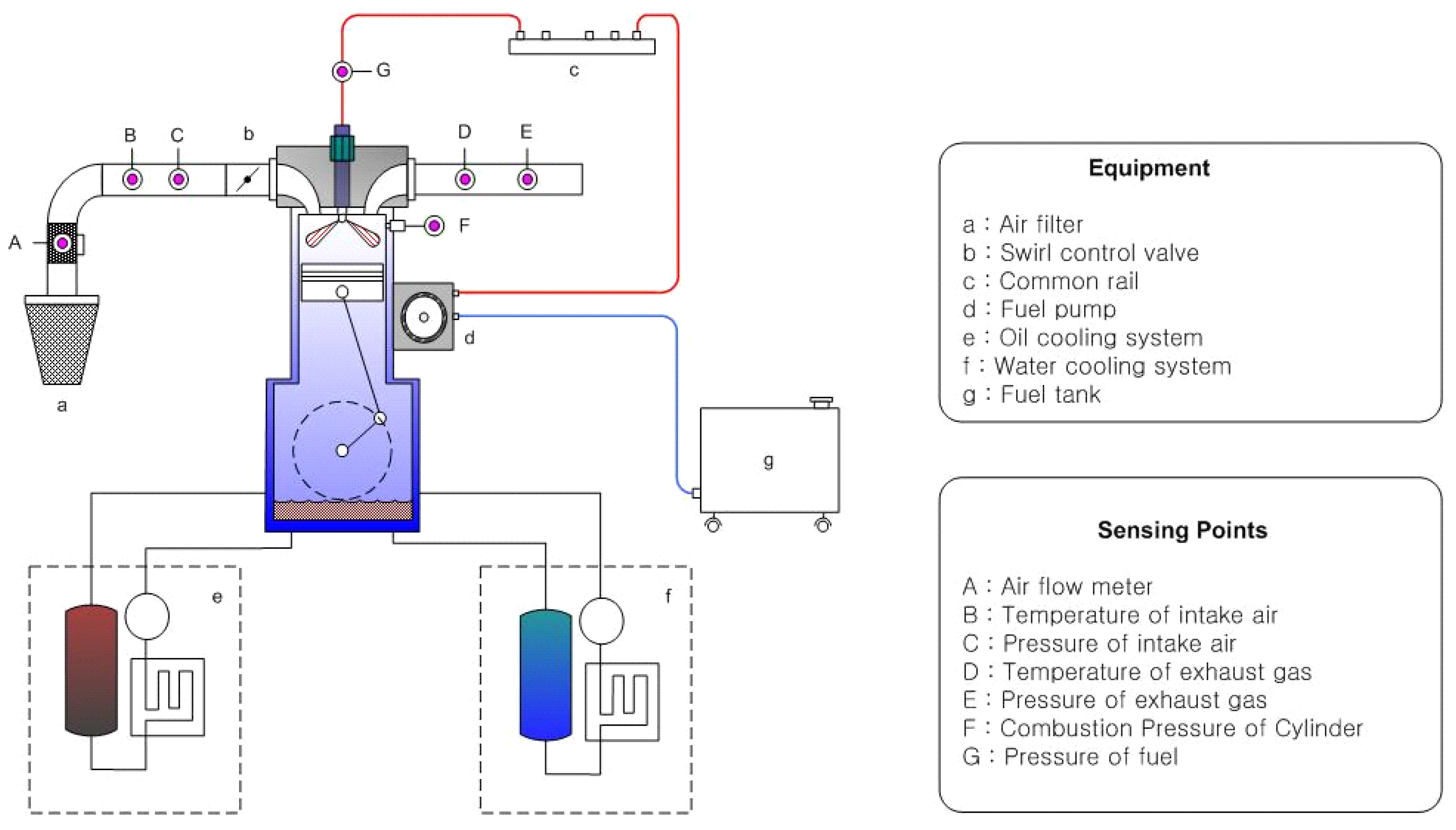
2.1. Experimental Apparatus
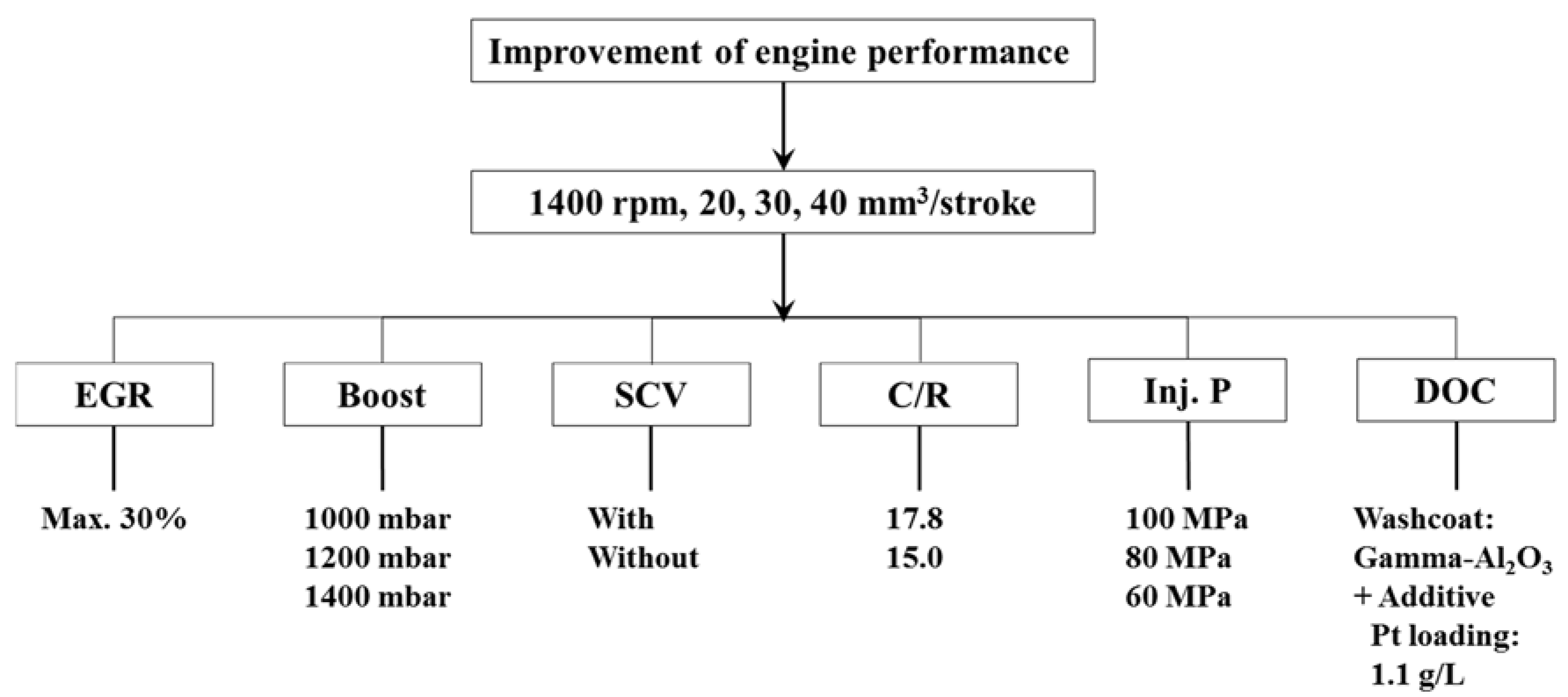
2.2. Determination of Experimental Conditions
3. Results and Discussion
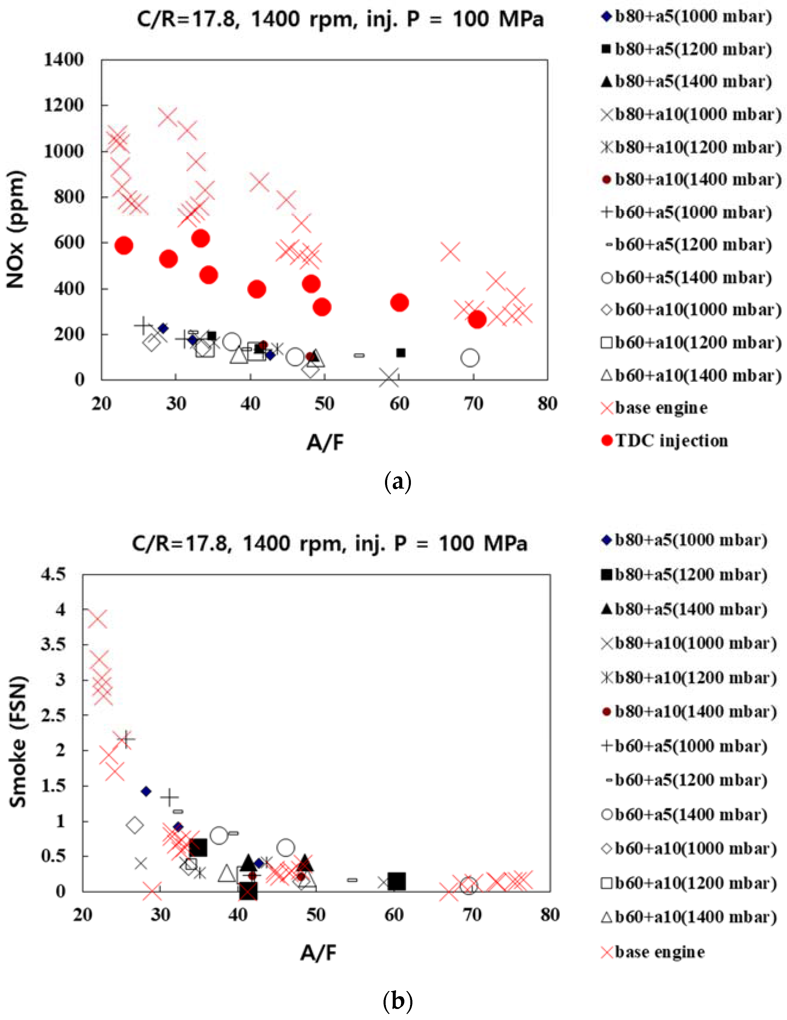
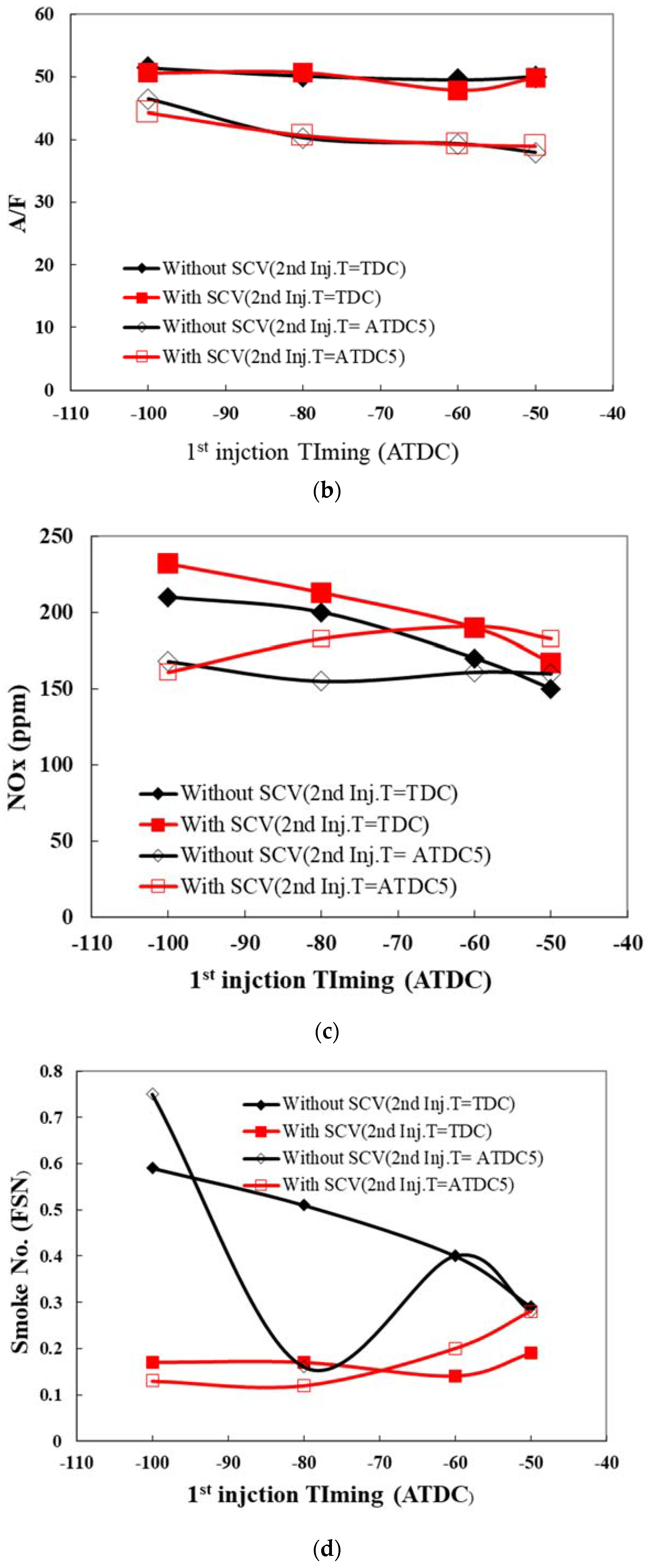
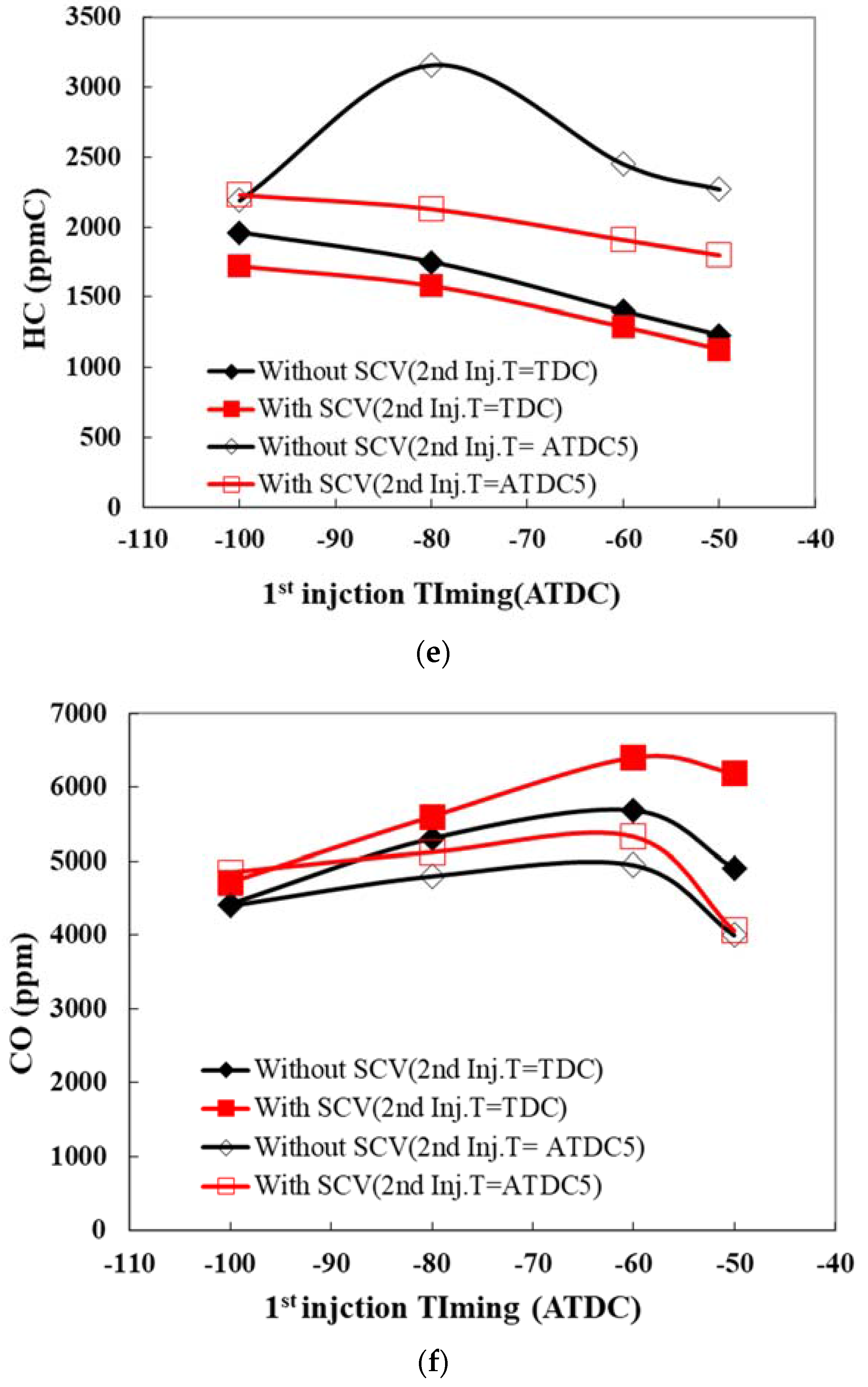
3.1. Consideration of Emission Characteristics and Combustion Control Factors for the Various Air-Fuel Ratios
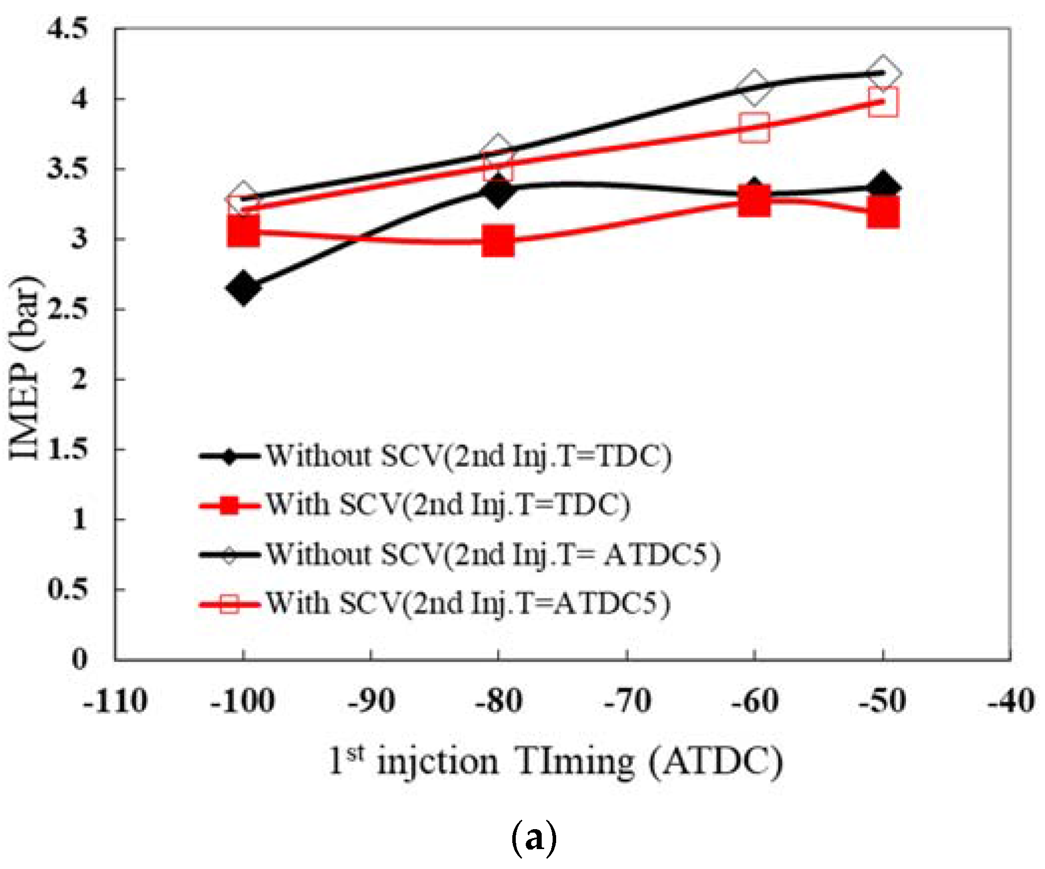
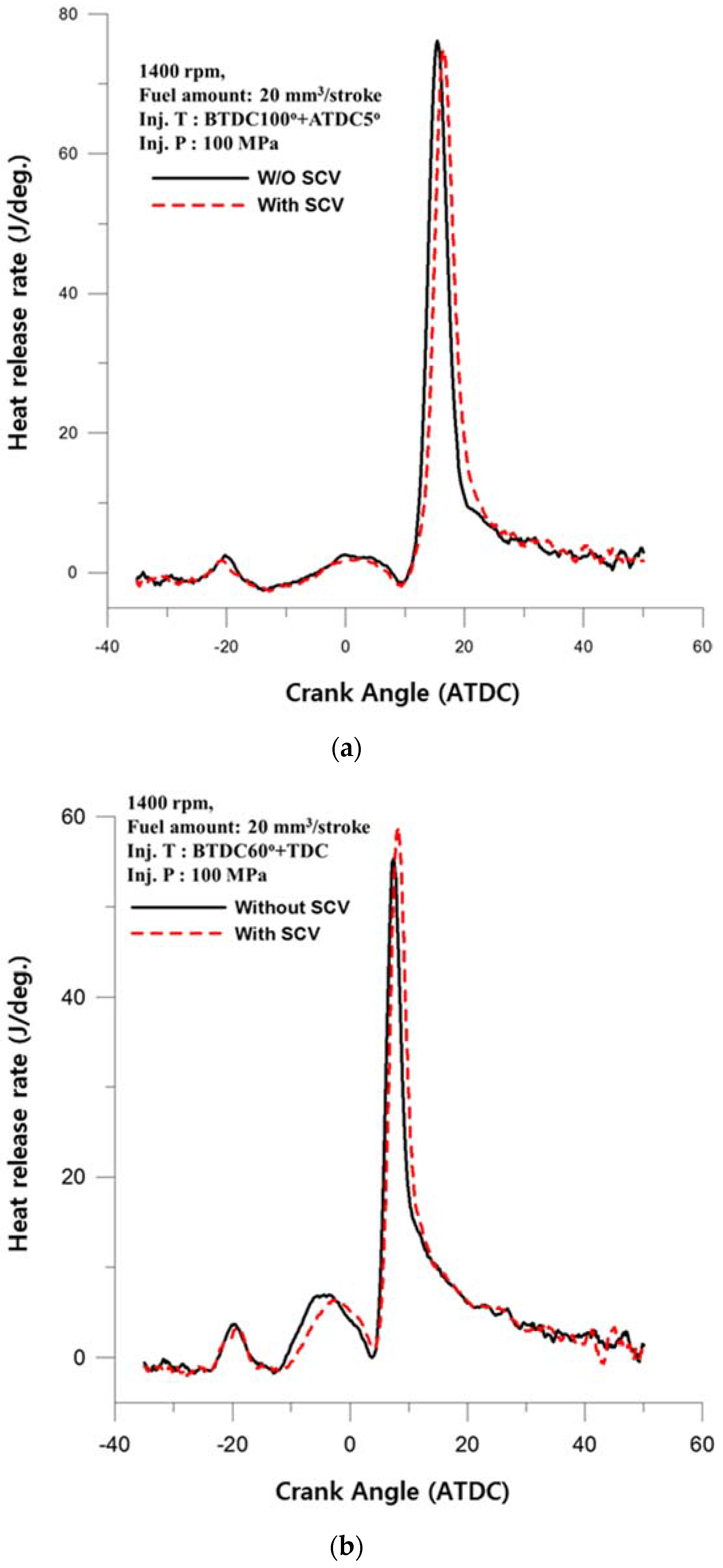
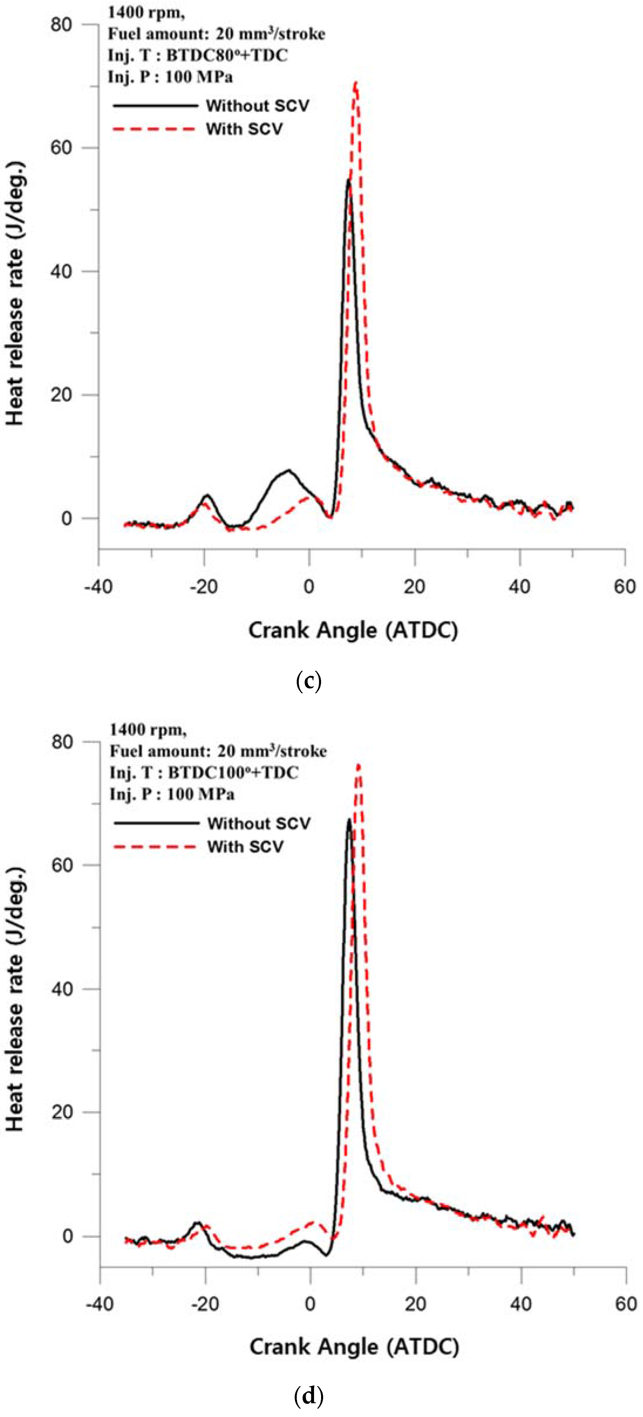
3.2. Effect on the Swirl Control Valve
- (1)
- The ignition delay of the 1st injection according to the SCV
- (2)
- Increase in the effect on the 2nd injection timing as the 1st injection time is advanced
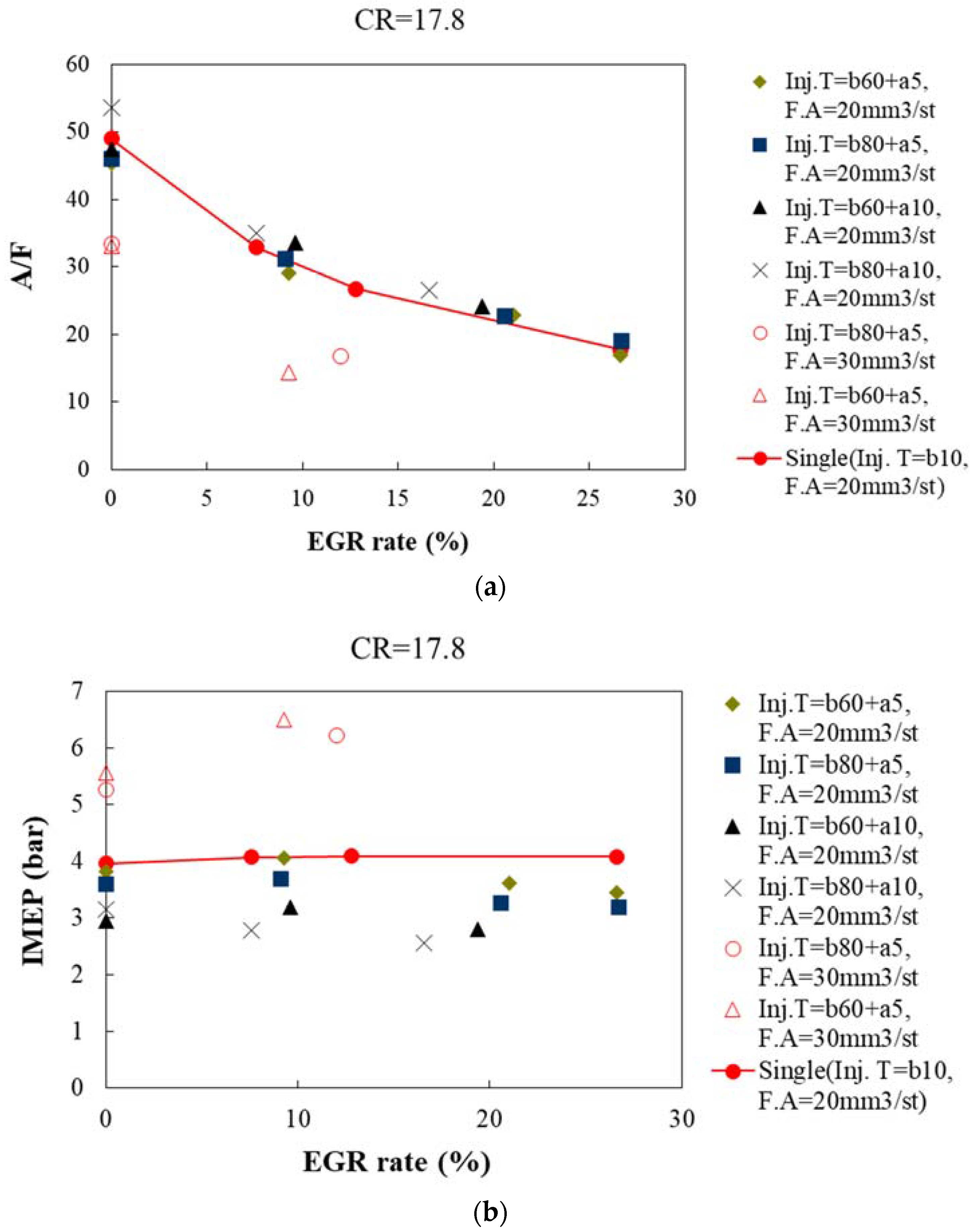
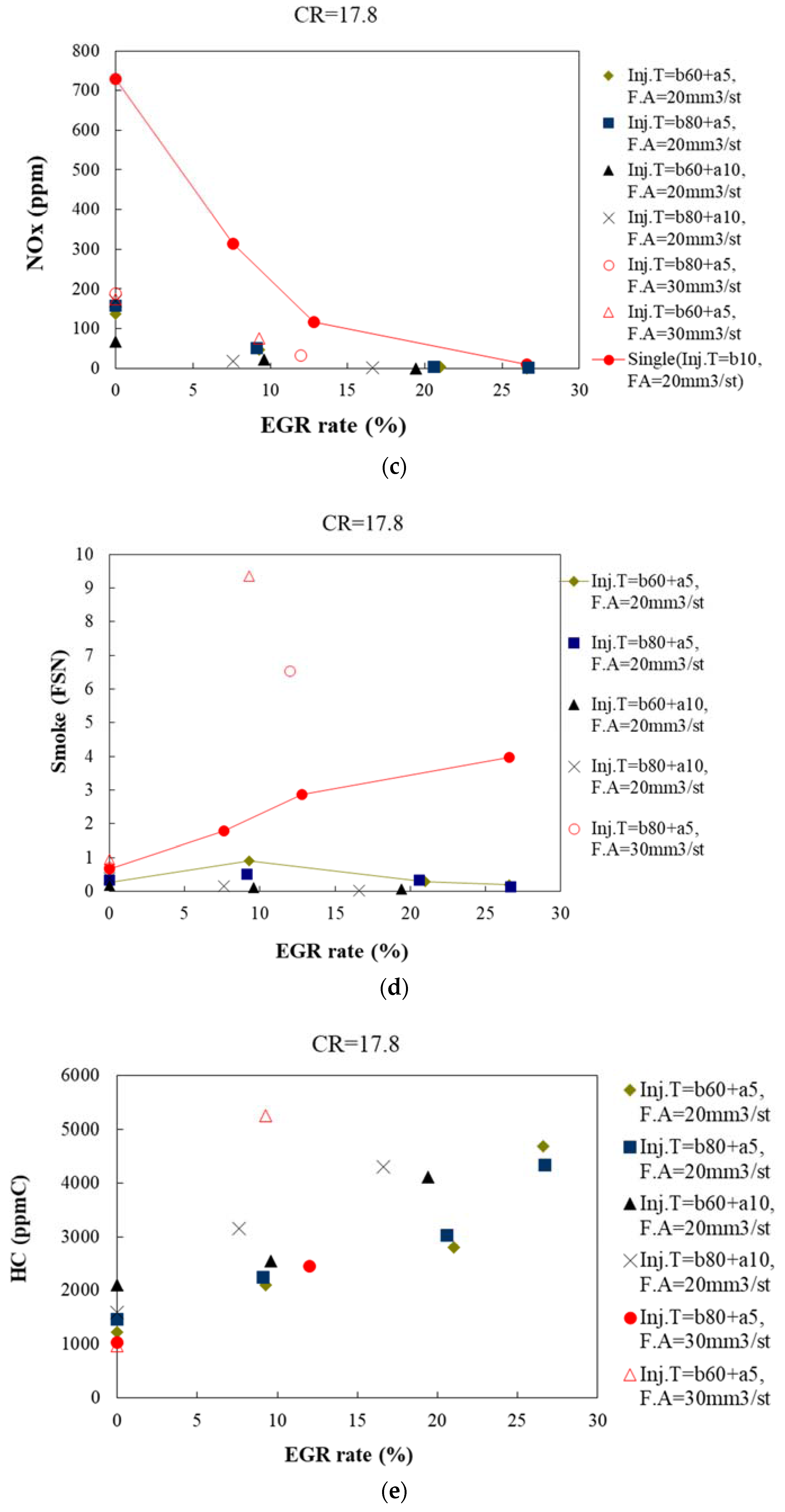
3.3. Effect on the Exhaust Gas Recirculation
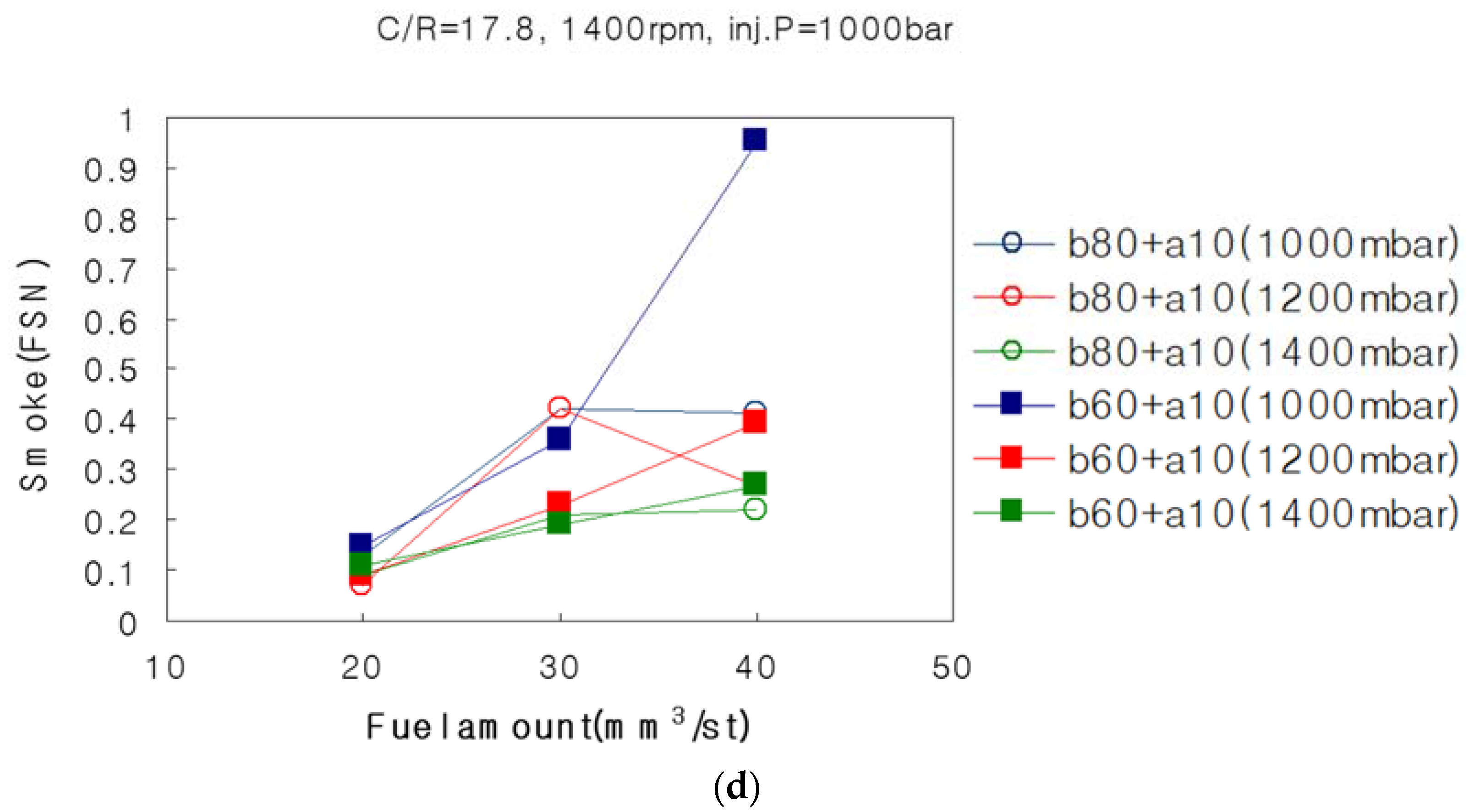
3.4. Effect on the Charging Pressure
4. Conclusions
- (1)
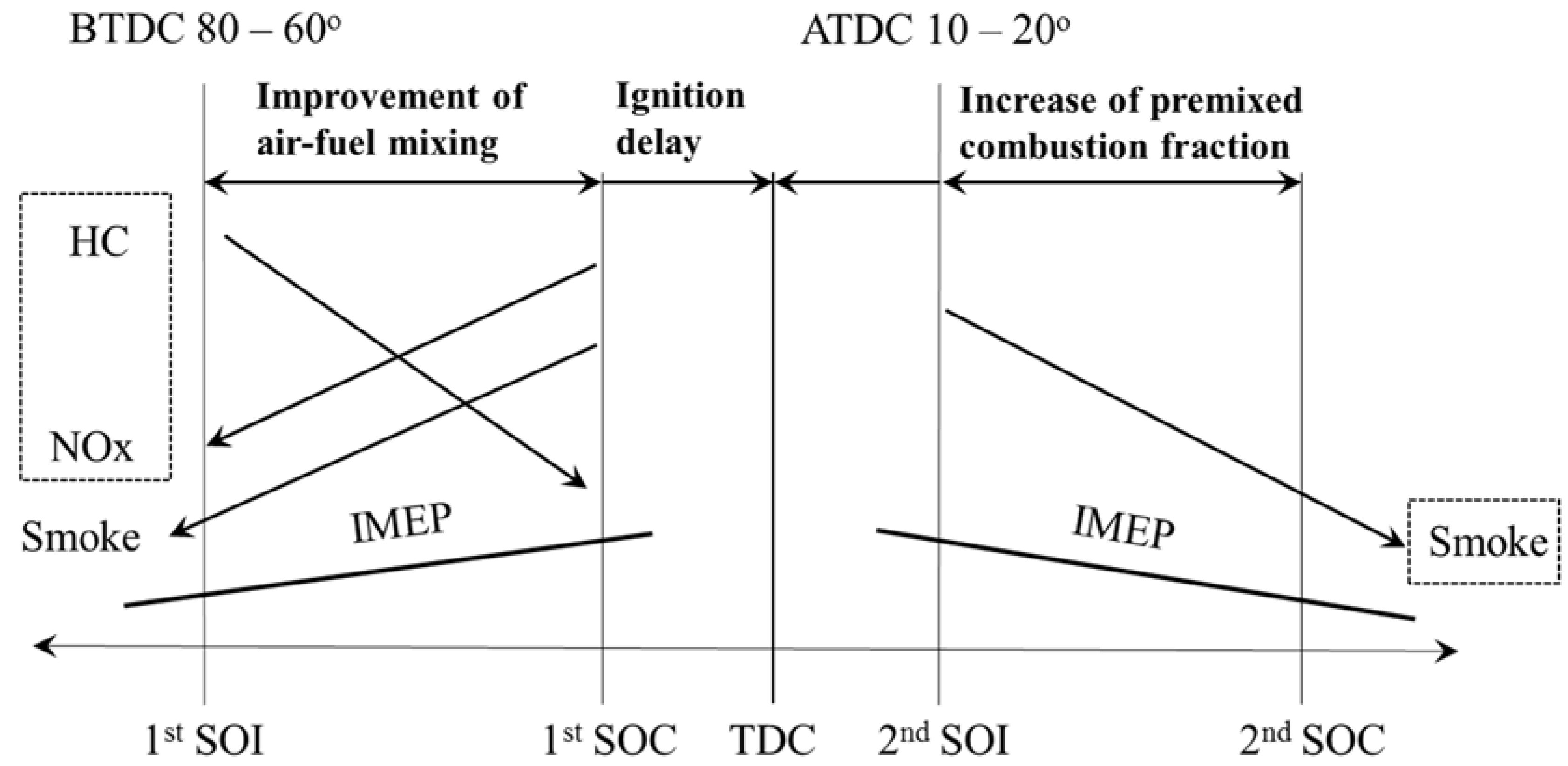
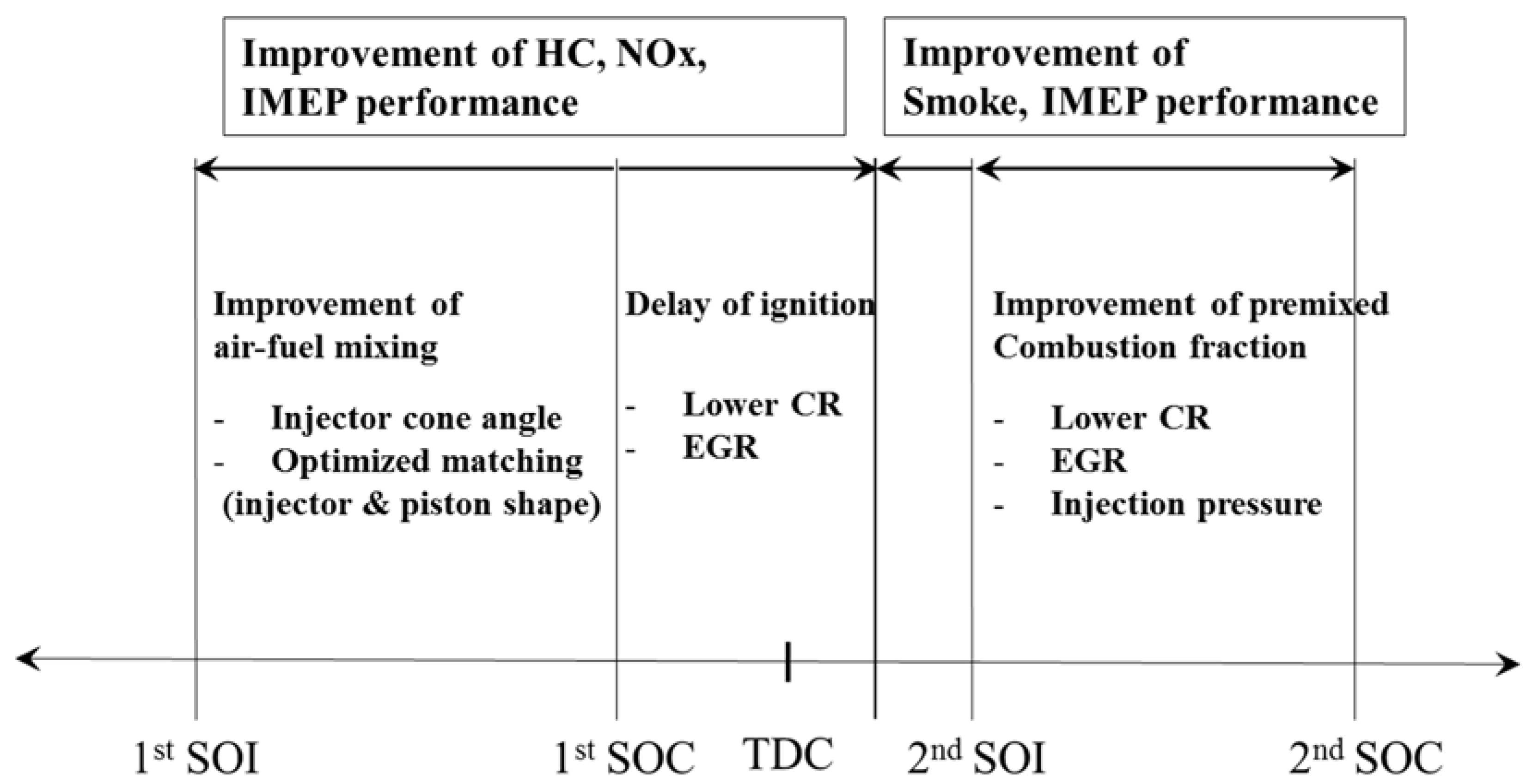
- Considering the characteristics of injection timing, exhaust gas and IMEP, the appropriate 1st injection timing has been determined to be BTDC 80–60° and a 2nd injection timing close to ATDC 10° has been determined to be reasonable. The results from the characteristics stated above were considered for ways to improve performance. The way to improve the performance is a delay such that the ignition of first fuel injection is close to TDC so that the combustion is active. The second fuel injection effect is to promote the premixing rate by possibly delaying the ignition.
- (2)
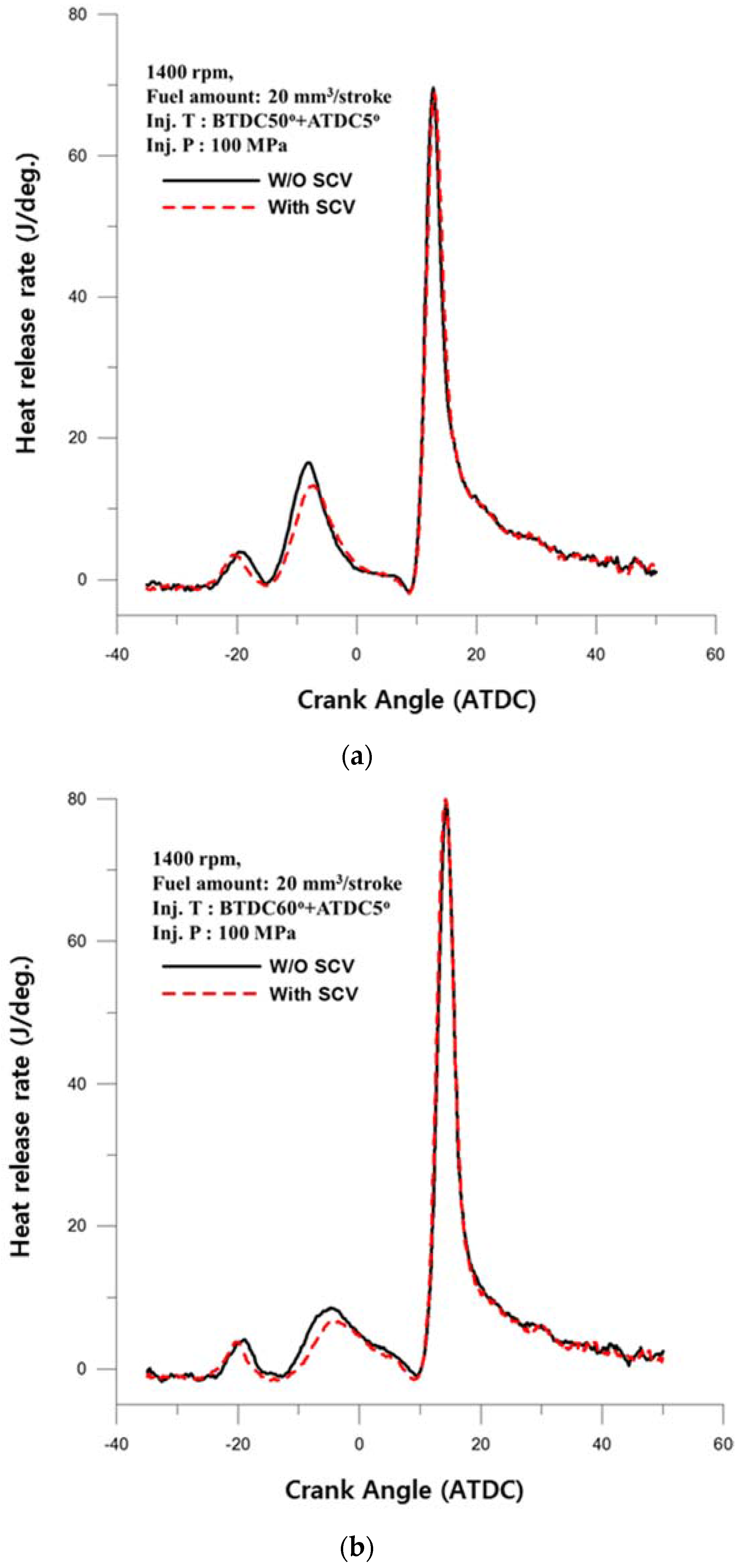
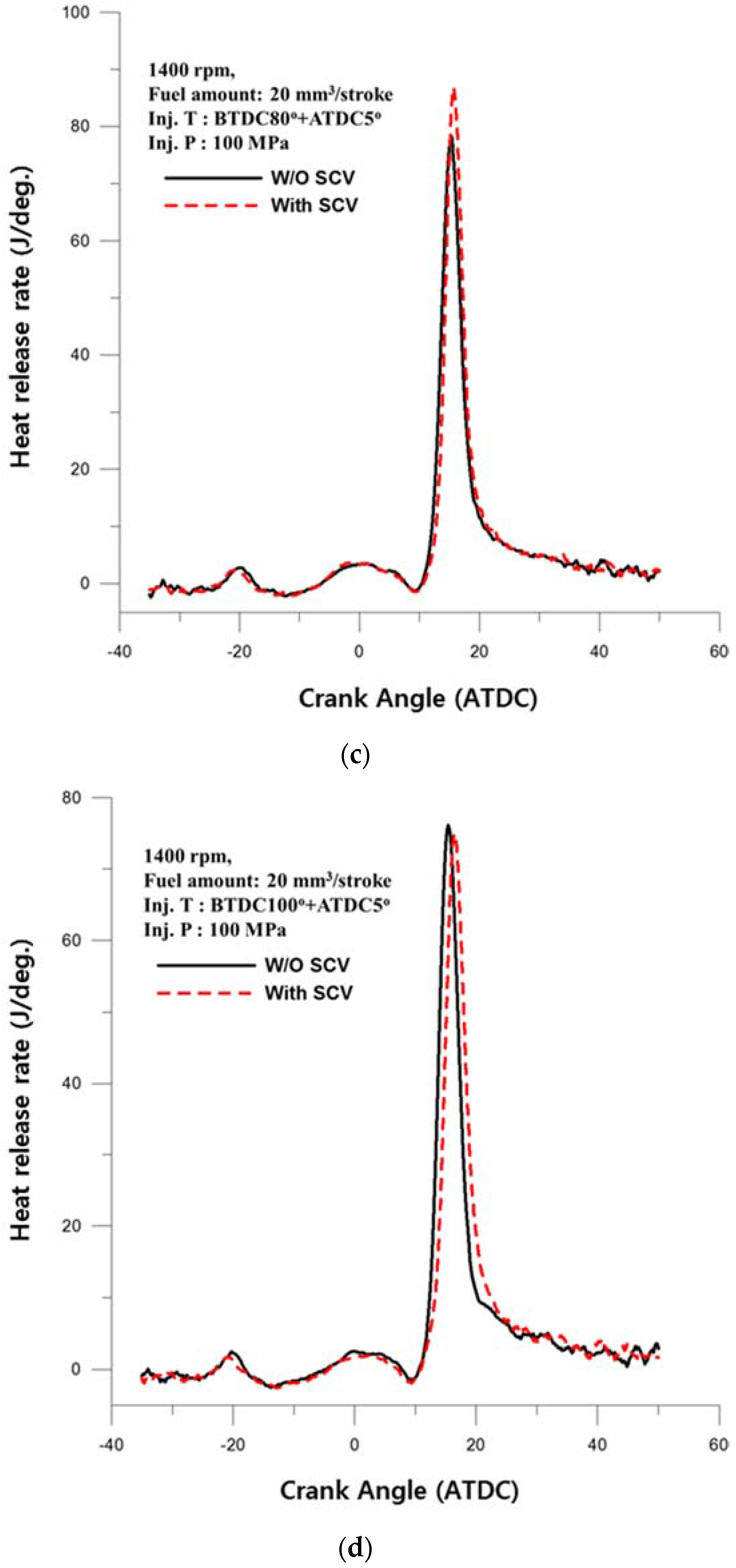
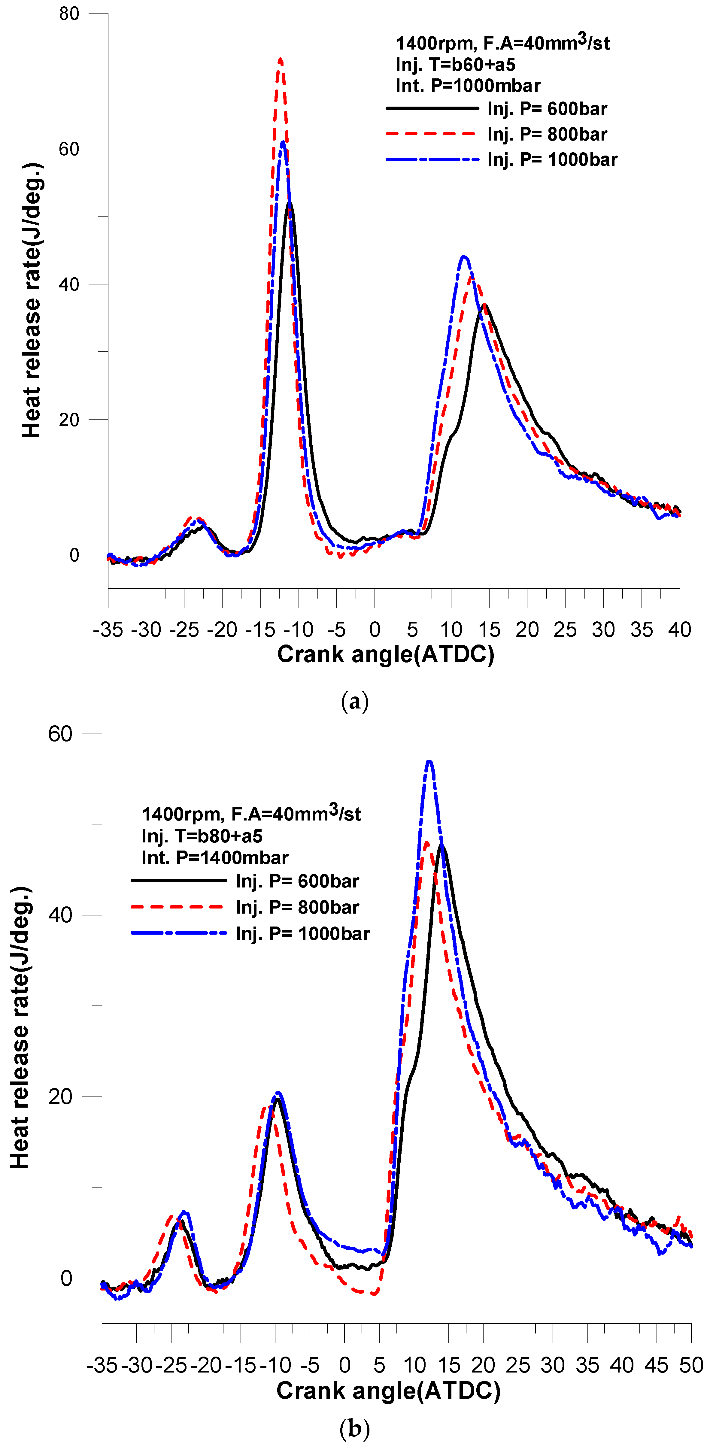
- The main phenomena in comparison with the results of the heat release rate are as follows:
- (a)
- The ignition delay of the 1st injection according to the SCV
- (b)
- Increase in the effect on the 2nd injection timing as the 1st injection time is advanced
- (3)
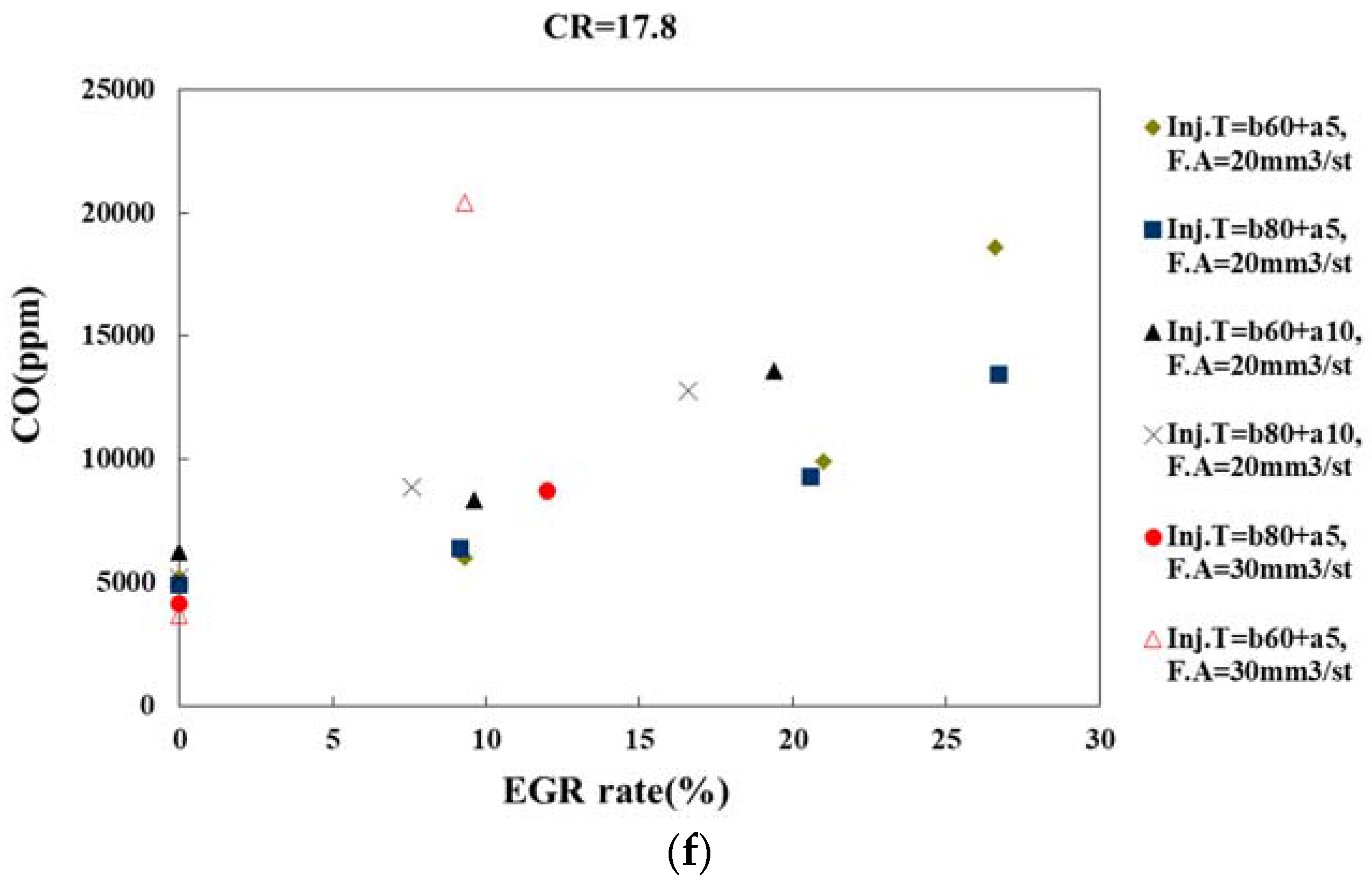
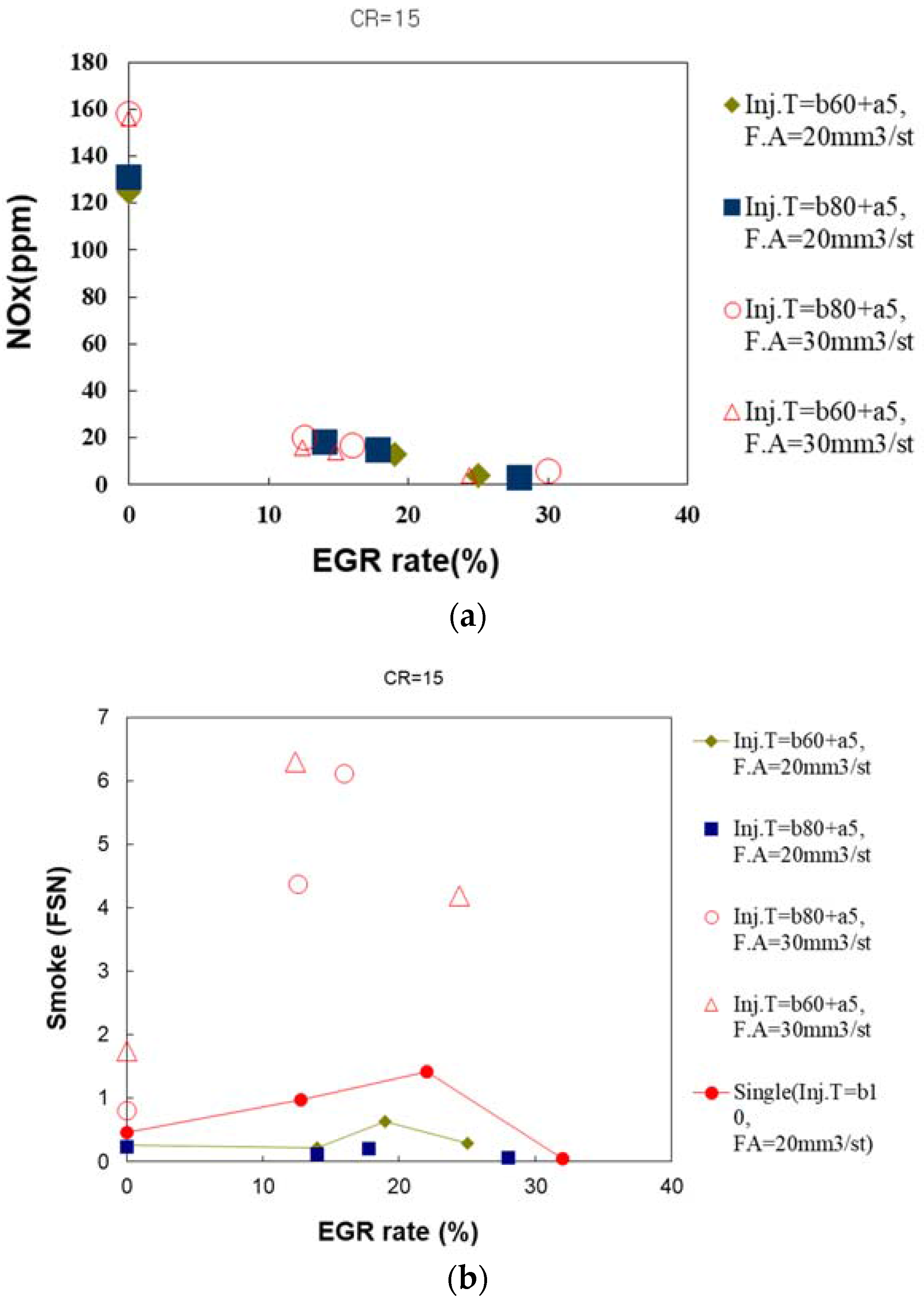
- The air-fuel ratio was evaluated at less than half by using EGR. IMEP showed no large variation but it could be confirmed that the highest IMEP is formed at about 10% of the EGR rate. As the injection amount of the split injection is 20 mm3/stroke to apply the HCCI methodology, the smoke is not reduced in accordance with the increasing EGR rate, however, in case of 30 mm3/stroke, it is dramatically increased according to the increase of the EGR rate.
- (4)
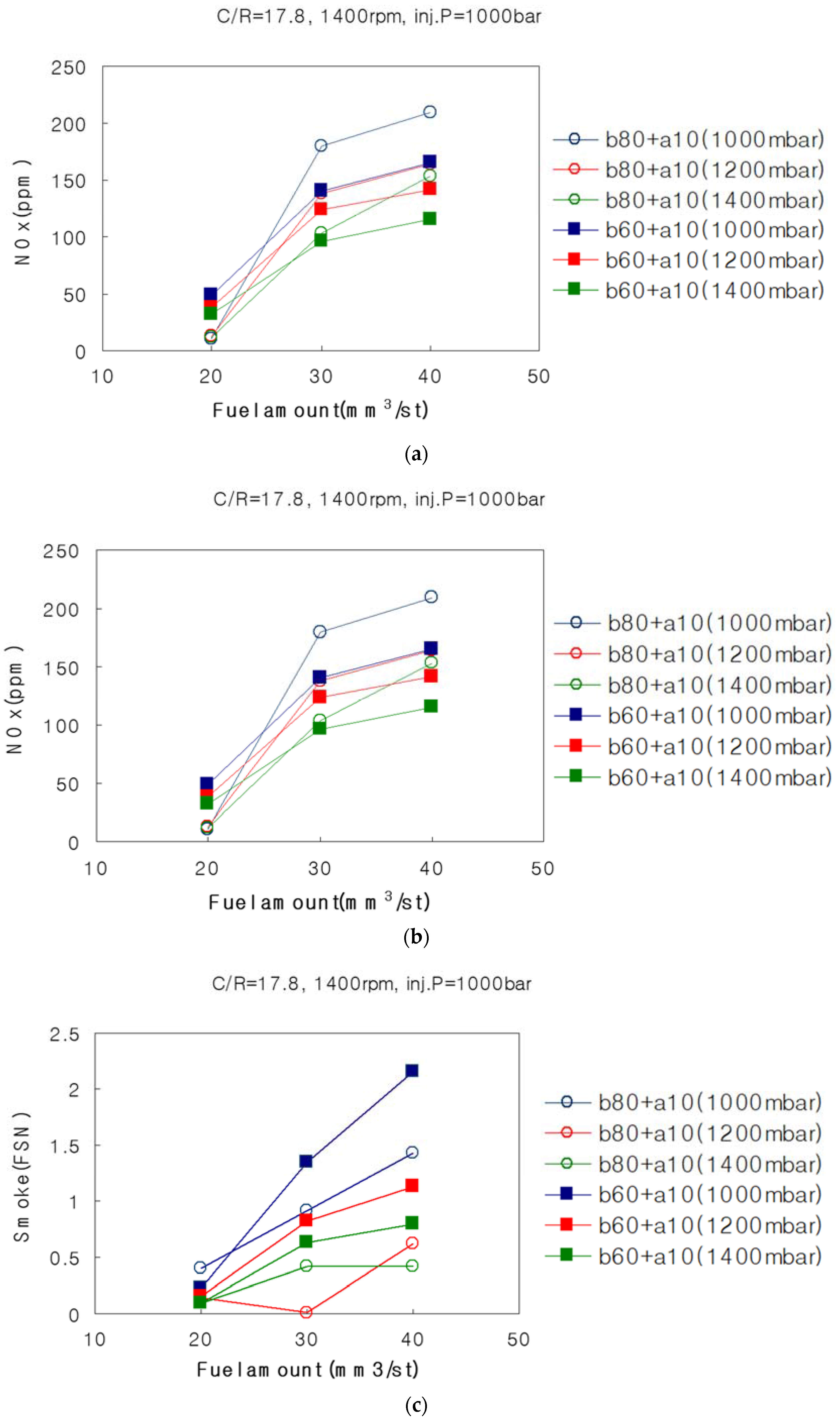
- It is possible to lower the boost pressure rate as the best premixing rate in terms of exhaust gas depends on the injection angle. It could be necessary to strengthen the dilution with a relatively higher boost pressure at the condition of the partial-HCCI for the excellent power performance case.
Acknowledgments
Author Contributions
Conflicts of Interest
References
- Simescu, S.; Ryan, T.; Neely, G.; Matheaus, A. Partial Pre-Mixed Combustion with Cooled and Uncooled EGR in a Heavy-Duty Diesel Engine. SAE Tech. Pap. 2002. [Google Scholar] [CrossRef]
- Yokota, H.; Kudo, Y.; Nakajima, H.; Kakegawa, T. A New Concept for Low Emission Diesel Combustion. SAE Tech. Pap. 1997. [Google Scholar] [CrossRef]
- Akagawa, H.; Miyamoto, T.; Harada, A.; Sasaki, S. Approaches to Solve Problems of the Premixed Lean Diesel Combustion. SAE Tech. Pap. 1999. [Google Scholar] [CrossRef]
- Kimura, S.; Aoki, O.; Ogawa, H.; Muranaka, S. New Combustion Concept for Ultra-Clean and High-Efficiency Small DI Diesel Engines. SAE Tech. Pap. 1999. [Google Scholar] [CrossRef]
- Hasegawa, R.; Yanagihara, H. HCCI Combustion in DI Diesel Engine. SAE Tech. Pap. 2003. [Google Scholar] [CrossRef]
- Kwon, O.Y.; Ryu, J.D.; Lee, K.H.; Lee, C.S. Flame and Combustion Characteristics of D.I HCCI Engine using a Visualization Engine. Trans. KSAE 2002, 10, 100–107. [Google Scholar]
- Song, B.H.; Kim, D.K.; Cho, N.H. A Cycle Simulation Method for an HCCI Engine using Detailed Chemical Kinetics. Trans. KSAE 2003, 11, 51–58. [Google Scholar]
- Onishi, S.; Jo, S.; Shoda, K.; Jo, P. Active Thermo-Atmosphere Combustion (ATAC)—A New Combustion Process for Internal Combustion Engines. SAE Tech. Pap. 1979. [Google Scholar] [CrossRef]
- Najt, P.; Foster, D. Compression-Ignited Homogeneous Charge Combustion. SAE Tech. Pap. 1983. [Google Scholar] [CrossRef]
- Takeda, Y.; Keiichi, N.; Keiichi, N. Emission Characteristics of Premixed Lean Diesel Combustion with Extremely Early Staged Fuel Injection. SAE Tech. Pap. 1996. [Google Scholar] [CrossRef]
- Aoyama, T.; Hattori, Y.; Mizuta, J.; Sato, Y. An Experimental Study on Premixed-Charge Compression Ignition Gasoline Engine. SAE Tech. Pap. 1996. [Google Scholar] [CrossRef]
- Ishibashi, Y.; Asai, M. Improving the Exhaust Emissions of Two-Stroke Engines by Applying the Activated Radical Combustion. SAE Tech. Pap. 1996. [Google Scholar] [CrossRef]
- Oakley, A.; Zhao, H.; Ladommatos, N.; Ma, T. Experimental Studies on Controlled Auto-ignition (CAI) Combustion of Gasoline in a 4-Stroke Engine. SAE Tech. Pap. 2001. [Google Scholar] [CrossRef]
- Lee, C.H.; Lee, K.H. An experimental study of the combustion characteristics in SCCI and CAI based on direct-injection gasoline engine. Exp. Therm. Fluid Sci. 2007, 31, 1121–1132. [Google Scholar] [CrossRef]
- Lee, K.; Lee, C. An Experimental Study of the Extent of the Operating Region and Emission Characteristics of Stratified Combustion Using the Controlled Autoignition Method. Energy Fuels 2006, 20, 1862–1869. [Google Scholar] [CrossRef]
- Lee, C.H.; Lee, K.H. An Experimental Study on the Combustion and Emission Characteristics of a Stratified Charge Compression Ignition (SCCI) Engine. Energy Fuels 2007, 21, 1901–1907. [Google Scholar] [CrossRef]
- Mauya, R.; Agawal, A. Experimental study of combustion and emission characteristics of ethanol compression ignition (HCCI) combustion engine. Appl. Energy 2011, 88, 1169–1180. [Google Scholar] [CrossRef]
- Kim, D.S.; Kim, M.Y.; Lee, C.S. Effect of premixed gasoline fuel on the combustion characteristics of compression ignition engine. Energy Fuels 2004, 18, 1213–1219. [Google Scholar] [CrossRef]
- Lu, X.; Han, D.; Huang, Z. Fuel design and management for the control of advanced compression-ignition modes. Prog. Energy Combust. Sci. 2011, 37, 741–783. [Google Scholar] [CrossRef]
- Charanlambides, A.G.; Sahu, S.; Hardalupas, Y.; Taylor, A.M.K.P.; Urata, Y. Evaluation of homogeneous charge compression ignition (HCCI) auto ignition development through chemiluminescence imaging and proper orthogonal decomposition. Appl. Energy 2018, 210, 288–302. [Google Scholar] [CrossRef]
- Chung, J.W.; Kang, J.H.; Kim, B.S.; Kang, W.; Kim, H.C. A Study on the Diesel DI-HCCI Combustion Characteristics using 2-stage Injection Method. Trans. KSAE 2004, 12, 66–73. [Google Scholar]


| Engine Type | Single Cylinder | Base Engine |
|---|---|---|
| Fuel type | Diesel | Diesel |
| Num. of cylinder—Bore × Stroke (mm) | 1—102 × 100 | 4—102 × 100 |
| Stroke volume (cc/cylinder) | 817 | 817 |
| Number of intake valve (/cylinder) | 2 | 1 |
| Compression ratio | Variable (Max. 17.8) | 17.8 |
| Fuel supply system | Common-rail | Mechanical (VE pump) |
| Num. of nozzle hole × dia. (mm) | 5 × φ0.168 | 5 × φ0.26 |
| Injection pressure (bar) | <1350 bar | 220 bar |
| Injection timing | Various | BTDC 13° |
| Max. rpm/Max. pressure (bar) | 4000/120 | 2300/100 |
| Intake charging | Supercharging | W/O |
| Swirl | Variable (SCV) | - |
| EGR | With | W/O |
| Conrad/Crank radius (mm) | 167/50 | 167/50 |
© 2017 by the authors. Licensee MDPI, Basel, Switzerland. This article is an open access article distributed under the terms and conditions of the Creative Commons Attribution (CC BY) license (http://creativecommons.org/licenses/by/4.0/).
Share and Cite
Lee, C.; Chung, J.; Lee, K. Emission Characteristics for a Homogeneous Charged Compression Ignition Diesel Engine with Exhaust Gas Recirculation Using Split Injection Methodology. Energies 2017, 10, 2146. https://doi.org/10.3390/en10122146
Lee C, Chung J, Lee K. Emission Characteristics for a Homogeneous Charged Compression Ignition Diesel Engine with Exhaust Gas Recirculation Using Split Injection Methodology. Energies. 2017; 10(12):2146. https://doi.org/10.3390/en10122146
Chicago/Turabian StyleLee, Changhee, Jaewoo Chung, and Kihyung Lee. 2017. "Emission Characteristics for a Homogeneous Charged Compression Ignition Diesel Engine with Exhaust Gas Recirculation Using Split Injection Methodology" Energies 10, no. 12: 2146. https://doi.org/10.3390/en10122146