1. Introduction
FPGA has received tremendously wide applications in the variable field of industries these days, while the application in portable electronic devices is limited. One reason could be that conventional Static Random Access Memory (SRAM) FPGA needs a large circuit board foot print and consumes considerable high power. However, new technologies based on flash like nonvolatile FPGA are emerging to overcome these drawbacks. With advantages like design flexibility and fast time to marketing, FPGA is quite promising in the field of portable electronic devices [
1]. For all portable electronic devices, battery management is the first step before commercialization. It is necessary to design battery management systems specifically for FPGA based portable electronic devices. On the other hand, new battery chemistry and emerging advanced algorithms are pushing traditional smart battery chargers or battery management circuits to their limits. The high speed hard-wired logic of FPGA can greatly enhance the computation capability of battery management circuits based on FPGA, which can implement all the necessary functions of battery management while leaving room for individual customization. FPGA based battery management algorithms can be specifically designed for the different battery chemistries of different devices, which can be updated easily even at later stages of product design. It is also profitable to integrate the battery management function in FPGA to achieve compact, simple, and lower cost portable devices. Therefore, in this paper, a novel concept of incorporating all the functionality of smart battery management systems into the FPGA used by portable electronic devices is proposed [
2].
The smart battery management system mainly can be summarized into four aspects: (1) smart charging; (2) battery balancing; (3) smart discharging; and (4) safety operating [
3,
4,
5]. Among those four aspects of smart battery management, smart charging is the most critical and elaborately discussed here. Generally, to achieve the targets of high charging efficiency, long cycle lives, and short charging times, charging procedure should follow specific charging profiles that are largely dependent on the battery chemistry. For instance, the constant current (CC) method is sufficient to charge nickel batteries, while the constant current/constant voltage (CC/CV) method is wildly utilized over the charging of Li-ion batteries. However, conventional charging methods cannot satisfy the requirements of fast charging. For example, the CC/CV method for Li-ion batteries seriously extends the charging time during the CV charging period and decreases the life of the battery at the same time [
6]. Therefore many new battery charging methods have been researched in the literature [
4,
5,
6,
7,
8,
9,
10,
11,
12,
13,
14,
15,
16]. Multistage charging [
6,
7,
8] is proposed to apply different charging currents to optimize charge rates according to different states of charge (SOC). The search for optimal charging patterns is a combinatorial optimization problem, and several optimization techniques like genetic algorithm (GA), ant colony system (ACS), and particle swarm optimization (PSO) methods have been researched to solve these issues [
9,
10,
11,
12]. Pulse charging applies a pulse charging current, followed by a rest period or a discharge pulse, which is claimed to be optimal since pulse charging allows the ions to diffuse and distribute more evenly through the battery, thus improving the charging speed and efficiency [
13,
14]. In addition, pulse charging can increase the charging efficiency and improve the accuracy of voltage measurement at the end of each cycle. The difficulty with the multistage charging is a complex computation requirement, which makes it not suitable to be integrated into the commercial battery charging circuit. However, this can be easily solved with the proposed FPGA based battery management system. In this paper, one novel charging algorithm, which combines the merits of multistage charging and pulse charging, is proposed.
The objective of this paper is to verify the feasibility of the proposed smart battery management system especially suitable for FPGA based portable devices. The given detailed analysis helps researchers to understand precisely the FPGA based smart battery management system’s operation. One novel charging algorithm combing the advantages of multistage charging and pulse charging is proposed and implemented in the hardware prototype. Simulation and experimental results from the developed prototype are demonstrated to validate the analysis and design. The objectives are realized in the various sections.
2. FPGA Based Smart Battery Management System
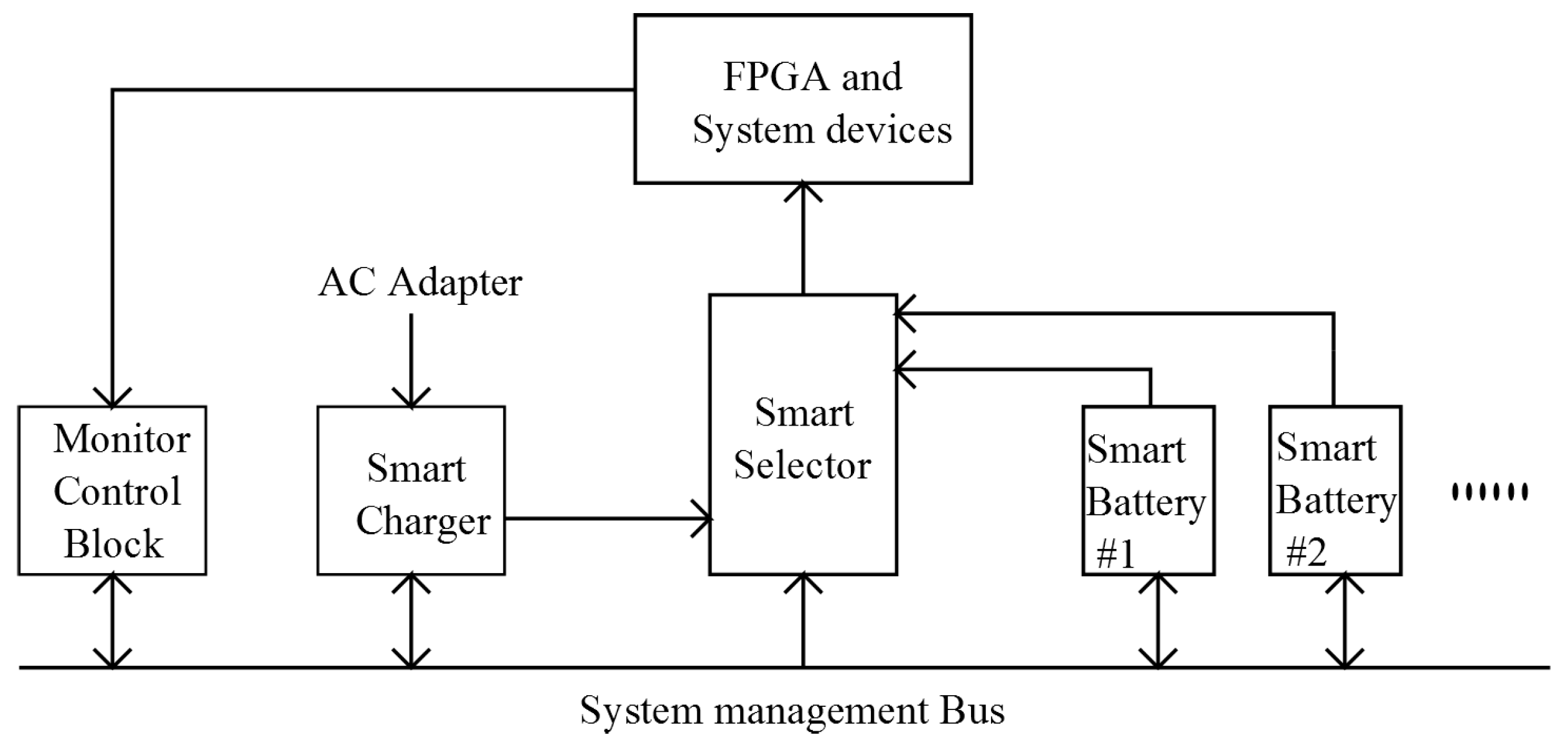
The basic task of a battery management system is to ensure that optimum use is made of the energy inside the battery powering the portable product and that the risk of damage inflicted upon the battery is minimized. This is achieved by monitoring and controlling the battery’s charging and discharging process. A FPGA based smart battery management system diagram is proposed in
Figure 1, which mainly consists of FPGA, a system management bus, a smart selector, smart battery packs, a smart charger, a monitor, and a control block. The battery packs are used to power the FPGA and other portable devices. The developed smart battery management algorithm, especially the smart charging algorithm, is programmed to the protected sector of FPGA and will be kept the same during the rest period of product development. Generally, a smart battery management system concept should cover four aspects: (1) smart charging; (2) battery balancing; (3) smart discharging; and (4) safety operating. They will be elaborately analyzed, discussed, and designed in the following sections.
2.1. Smart Charging
One of the most substantial issues of an FPGA based smart battery management system is smart charging, which decides the charging efficiency, long cycle life, and short charging time of the battery to a large extent. Battery chargers should achieve the following functions: (1) delivering charge to the battery; (2) optimizing the charge rate; and (3) terminating the charging [
3].
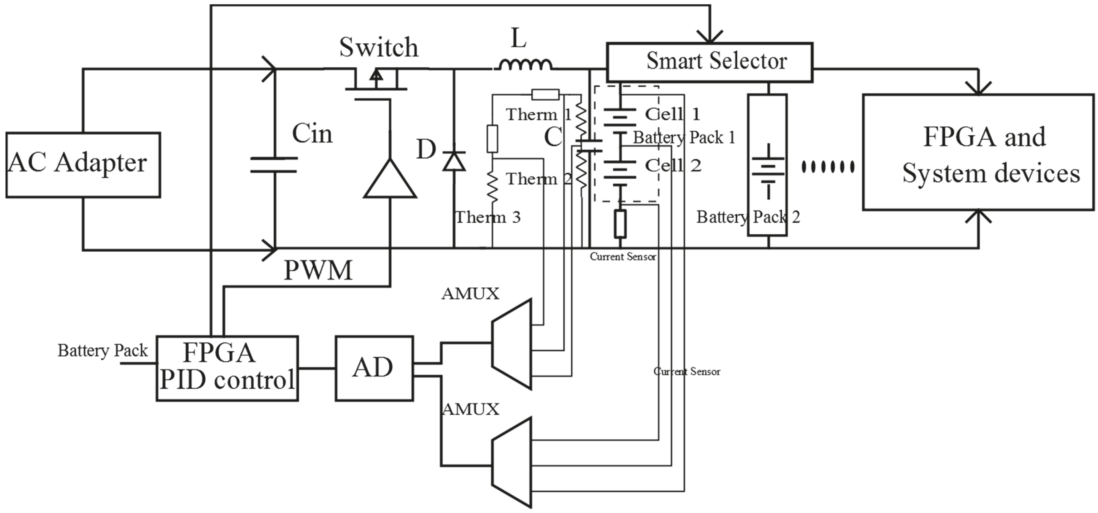
The proposed smart charging block is shown in
Figure 2. Modern portable devices usually require more operating voltage than a single-cell battery can provide. Thus in the proposed FPGA based smart battery management system, a serial connection of battery cells is adopted to increase the voltage level, and a parallel connection of battery cells is used to increase the battery pack capacity. Utility AC power is transformed into low voltage DC power through an AC adapter, and a conventional buck converter is employed to charge the battery packs. Proportional–Integral (PI) control is a very popular control method, which can provide good close-loop stability. Therefore, the PI method is applied in FPGA to control the charging current and charging voltage, following specific charging profile with respect to the battery chemicals. Analog multiplexer is utilized to reduce the number of required necessary analog to digital conversion devices (AD). AD devices transfer all the system information, like battery voltage, charging, and discharging current, to FPGA.
For the prototype researched in this paper, Li-ion battery packs are utilized. The operational battery voltage of each cell is 3.5 V to 4.3 V. Multistage charging has been used to optimize the charge rate of a Li-ion battery and is proven to have advantages such as prolonging the cycle life, enhancing charging energy efficiency, and reducing charging time. Pulse charging increases the accuracy of the voltage measurement at the end of each rest cycle. The state of charge (SOC) of the battery can be more accurately measured, and overcharging can be effectively avoided. A strict charging regime is necessary to properly and safely charge Li-ion batteries. The combination of these methods is quite promising to provide a better charging performance. In this section, a new charging algorithm based on multistage charging and pulse charging is proposed. The proposed smart battery management system topology is quite convenient and suitable for the application of this algorithm.
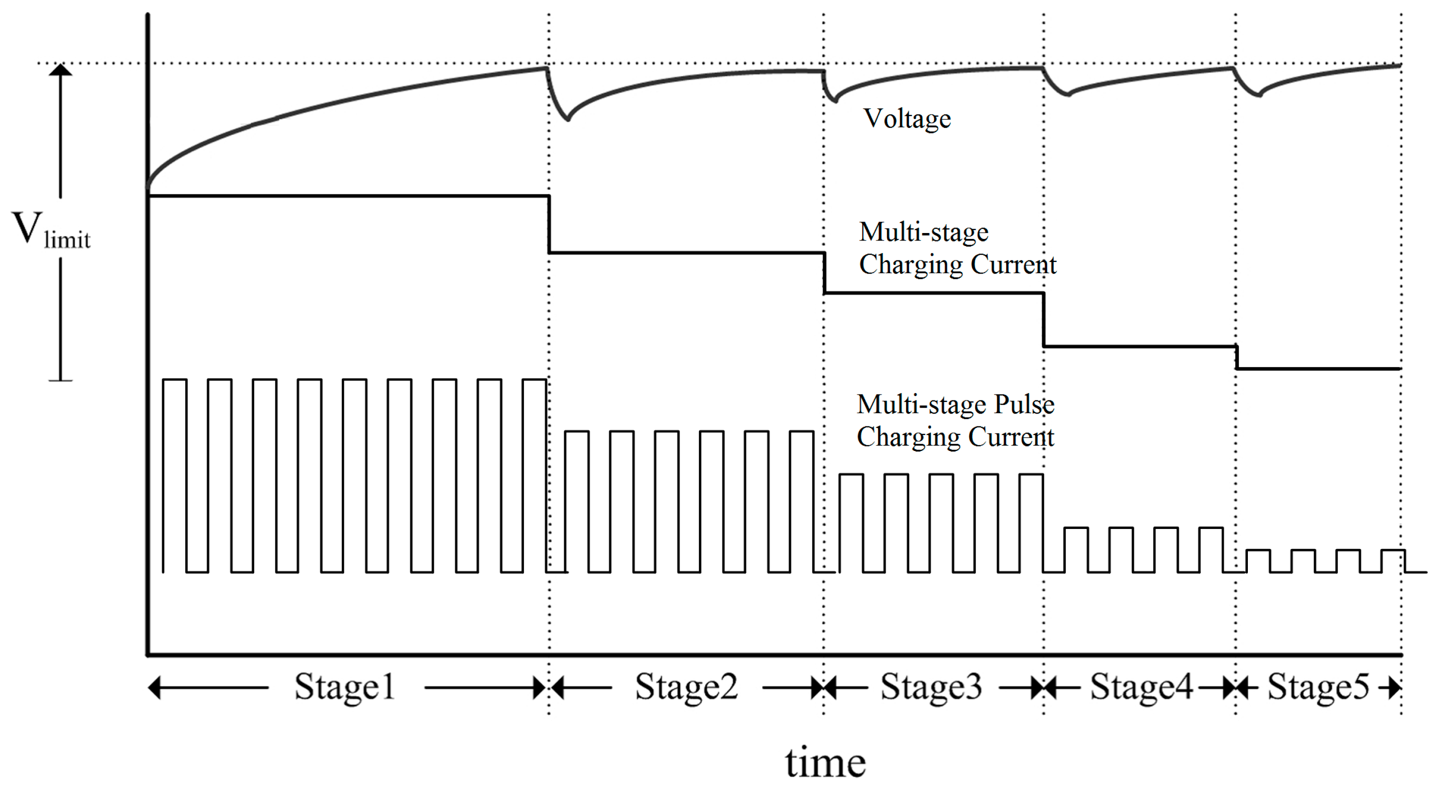
The voltage and current profile of multistage charging and the proposed multistage pulse charging diagram are illustrated in
Figure 3. As shown by the figure, different charging currents are applied to optimizing the charge rate according to different states of charge (SOC). Each time the voltage across the battery pack reaches the upper limit, the charging current is switched. The optimal current value for each stage is obtained using advance algorithms such as a genetic algorithm (GA). Therefore, the main principle of the proposed multistage pulse charging technique is quite straightforward; initialize the charging with a predefined number of charging stages and charging currents through analysis. For each stage, the pulse charging technique will be employed as shown in
Figure 3. The main principle of pulse charging is to apply a pulse charging current, followed by a rest period or a discharge pulse. Through several iterations of charging and discharging, the number of charging stages and the optimal charging current can be designed by solving combinatorial optimization problems using existing algorithms in the literature.
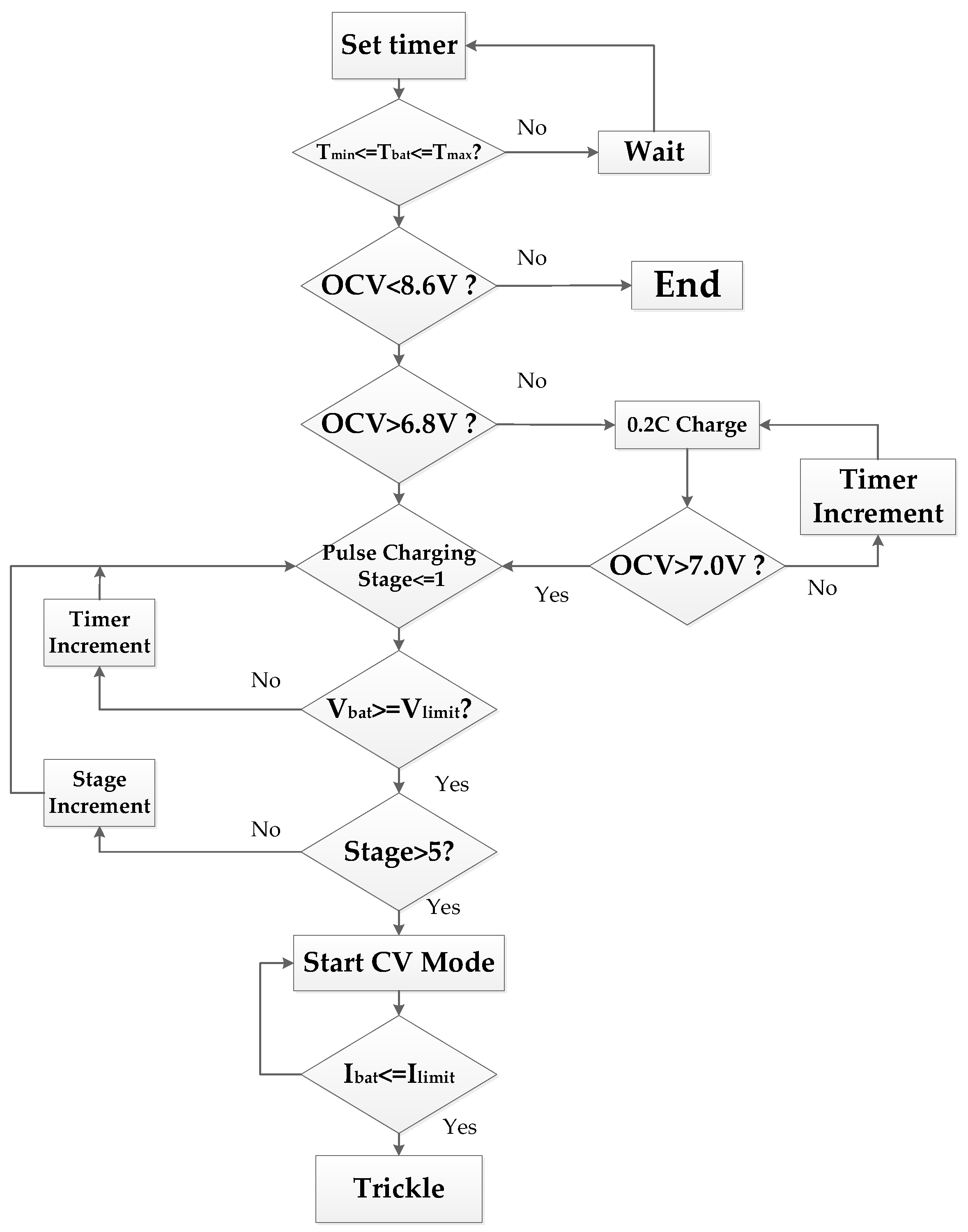
The proposed multistage pulse charging operation flowchart is shown in
Figure 4. The parameters of the flowchart are from the experimental prototype. Each battery pack consists of two Li-ion batteries, and the operational battery voltage of each cell is 3.5 V to 4.3 V. Before charging, the temperature of battery is measured to ensure that the battery is under the safe range of charging. During the whole charging procedure, the temperature is constantly measured due to safety concerns. Then the voltage across the battery is sensed, and, based on its value, an action is taken. The open circuit voltage of battery pack should be within 7.0 V to 8.6 V, otherwise the battery pack is over discharged. If the battery pack is over discharged and open circuit voltage (OCV) is less than 6.8 V, it starts charging with comparatively low charging current, like 0.2 C, in the flow chart. Based on the state of charge (SOC) of the battery pack, the charging current is decided. For each stage, pulse charging is applied, and the state of charge (SOC) is measured during the rest period of pulse charging. Each time the battery voltage pack reaches the upper limit, the number of charging stages is increased and a new charging current is applied. When the number of stages is larger than the designed value (5 in the chart), a constant voltage charging mode (CV) mode is started. Charging current decreased continuously. The charging procedure is terminated when the charging current drops below the limit or the time of charging is up. Other charge termination techniques can also be implemented in this algorithm, e.g., voltage drop or temperature rise.
2.2. Battery Balancing
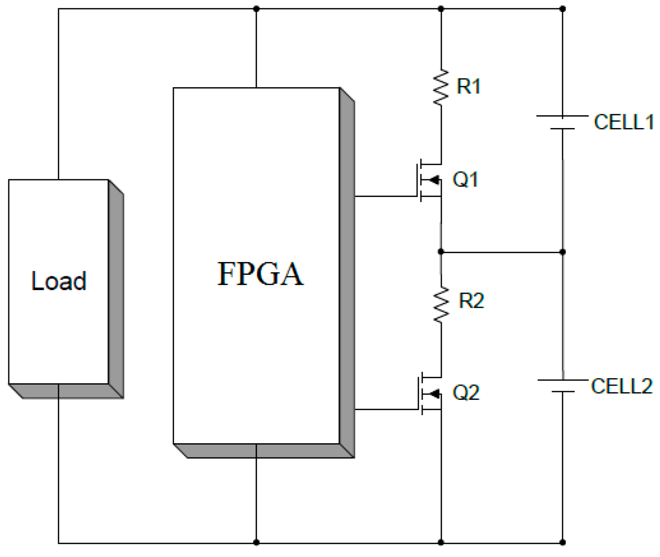
For the proposed FPGA based smart battery management system, two cells are connected in series to give sufficient nominal voltage for portable devices with variable voltage level requirements. However, problems can happen when the two cells have different capacities or charge levels. The unbalanced charge between cells can cause a lot of problems including; (1) reduced overall battery pack capacity; (2) reduced overall battery pack life; and (3) even cell damage sometimes. Battery balancing is necessary in a smart battery pack. In
Figure 5, the smart battery pack diagram with cell balancing is illustrated.
Cell balancing is achieved by connecting a parallel load to each cell that must be balanced. Typically, a series combination of a power transistor (MOSFET) and a current-limiting resistor are connected in parallel to each cell. If a cell has a higher voltage than the other cells, the bypass load to the cell is connected by closing the MOSFET so that a fraction of the charging current bypasses that cell. It is possible to balance the cells during the discharge phase, the charge phase, or both phases.
2.3. Smart Discharging and Safe Operating
One non-ideal performance of a battery is the recovery effect. The electrochemical reaction speed of battery usually cannot keep up with the consumption process, resulting in part of the energy being locked. With an increase of discharging current, the percentage of energy locked in the battery packs increases, which leads to an unnecessary reduction of battery powering time.
For the proposed FPGA based smart battery management system, a parallel connection of battery cells is used to increase the battery pack capacity. Smart discharging can be achieved by utilizing a smart selector block to interface the load and parallel connected battery packs. A multiplexer can be used as the smart selector. The recovery effect and discharge-profiling can be exploited to profile the discharge current in a manner conductive for extending battery powering time and life time. For example, battery packs can be rotated and selected through a smart selector under the control of FPGA to overcome the recovery effect.
During the whole operation of the proposed system, battery voltage, charging and discharging current, and the temperature of the battery cells and system are continuously monitored. All the information is transferred to FPGA to make corresponding actions to achieve the target of safe operating.
3. Smart Charging Block Design
This section presents the detailed design of a charging buck converter and the PI close loop control of the converter. The specifications of the design are input voltage from an AC adapter Vin = 12–15 V; switching frequency fs = 400 kHz; buck inductor L = 50 µH; output capacitor C = 12.5 µF; battery pack voltage Vb = 7.0–8.6 V (each battery pack consists of two Li-ion batteries and the operational battery voltage of each cell is 3.5 V to 4.3 V); Internal resistance of battery pack R = 0.1 Ω.
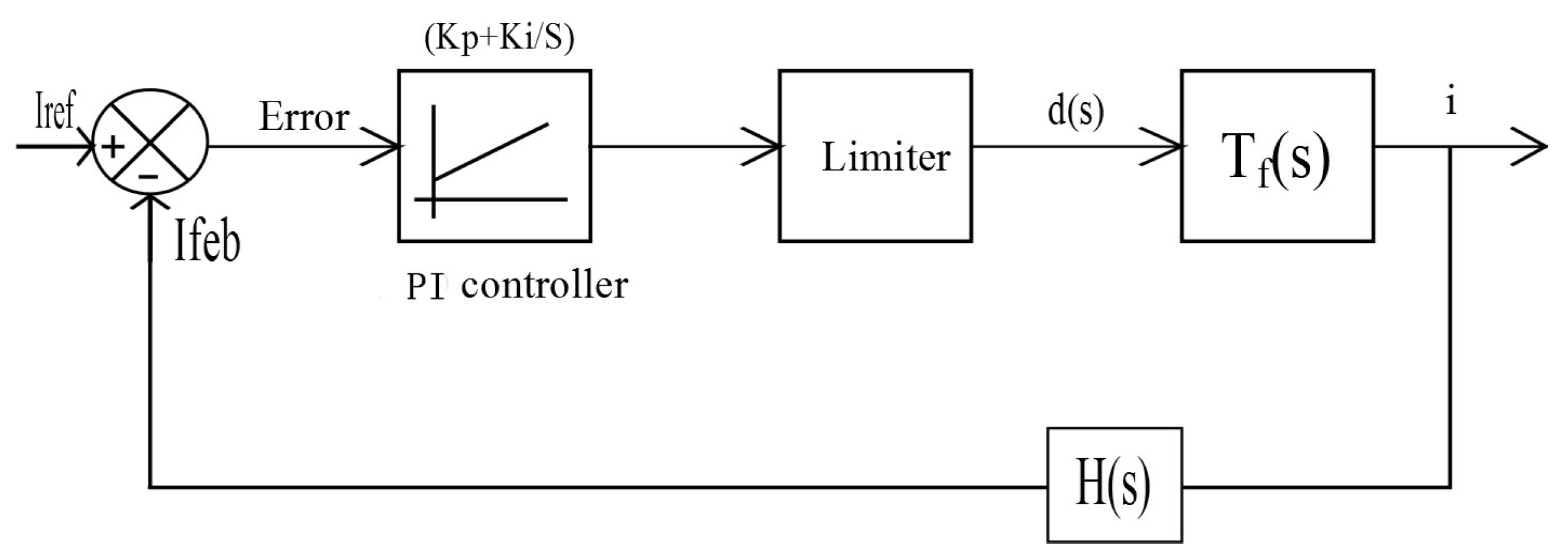
In order to regulate the charging current following a specific charging profile, a close loop controller is essential. A schematic diagram of the PI current control loop is shown in
Figure 6. The charging current is fed back to the FPGA with the gain of
H(
s). The output of the PI controller is used to obtain gating signals to control the switch. Current control involves the design of PI controller parameters in order to achieve stability and meet response criteria over a certain range. To design the controller, the duty ratio to the charging current transfer function is derived [
17,
18,
19].
State space functions of buck converter:
Transfer function of duty ratio to the charging current:
The current feedback gain is settled as 1/10:
The transfer function of a PI controller is given by
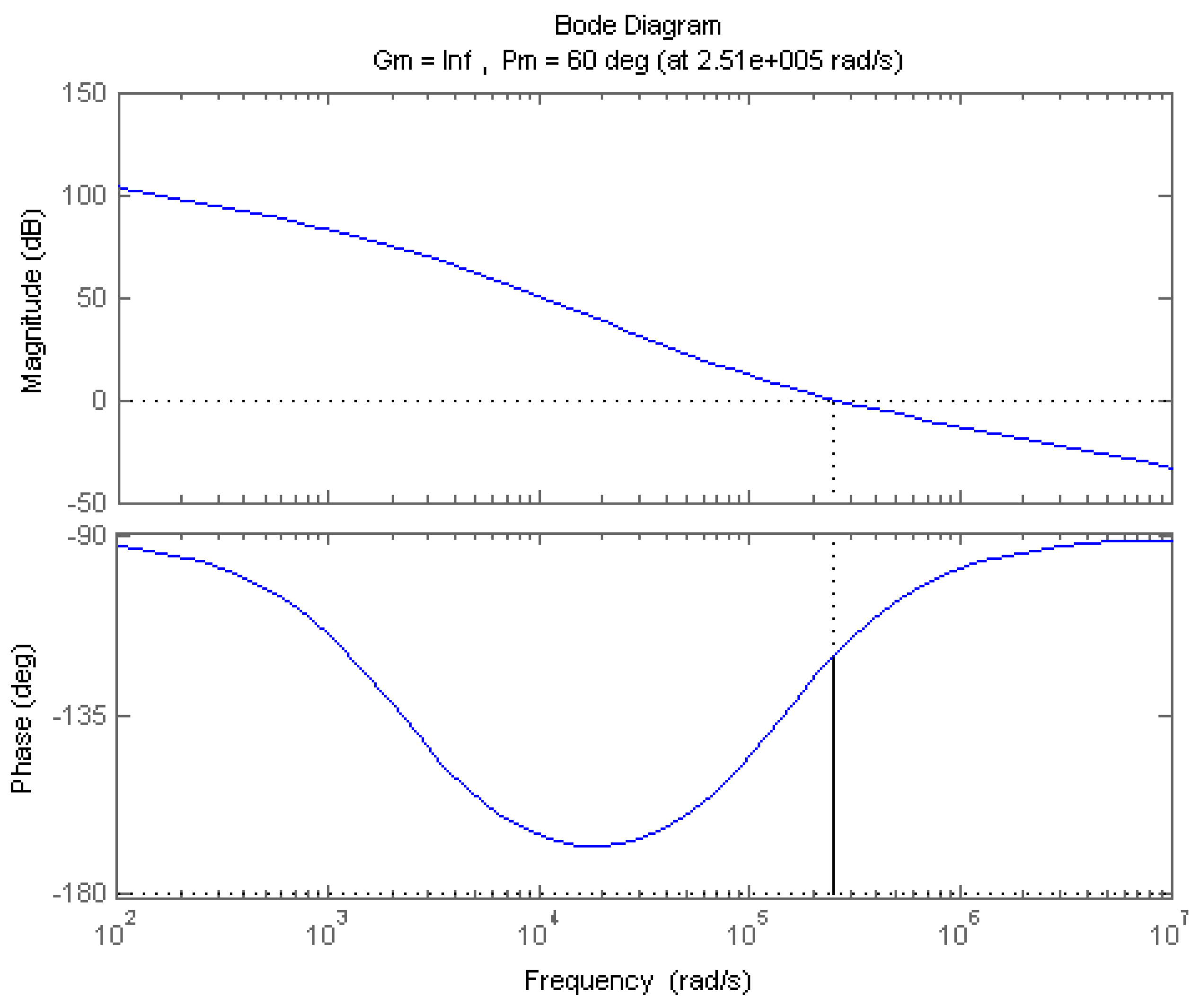
PI controller parameters are obtained to get a Phase Margin (PM) of 60° at the gain crossover frequency of 40 kHz. To achieve the set frequency response,
Kp = 0.9067 and
Ki = 131,580 are obtained. The bode plot for the compensated current control loop that meets the set design criteria is shown in
Figure 7. The low frequency gain is improved.
4. Simulation and Experimental Results of Smart Charging
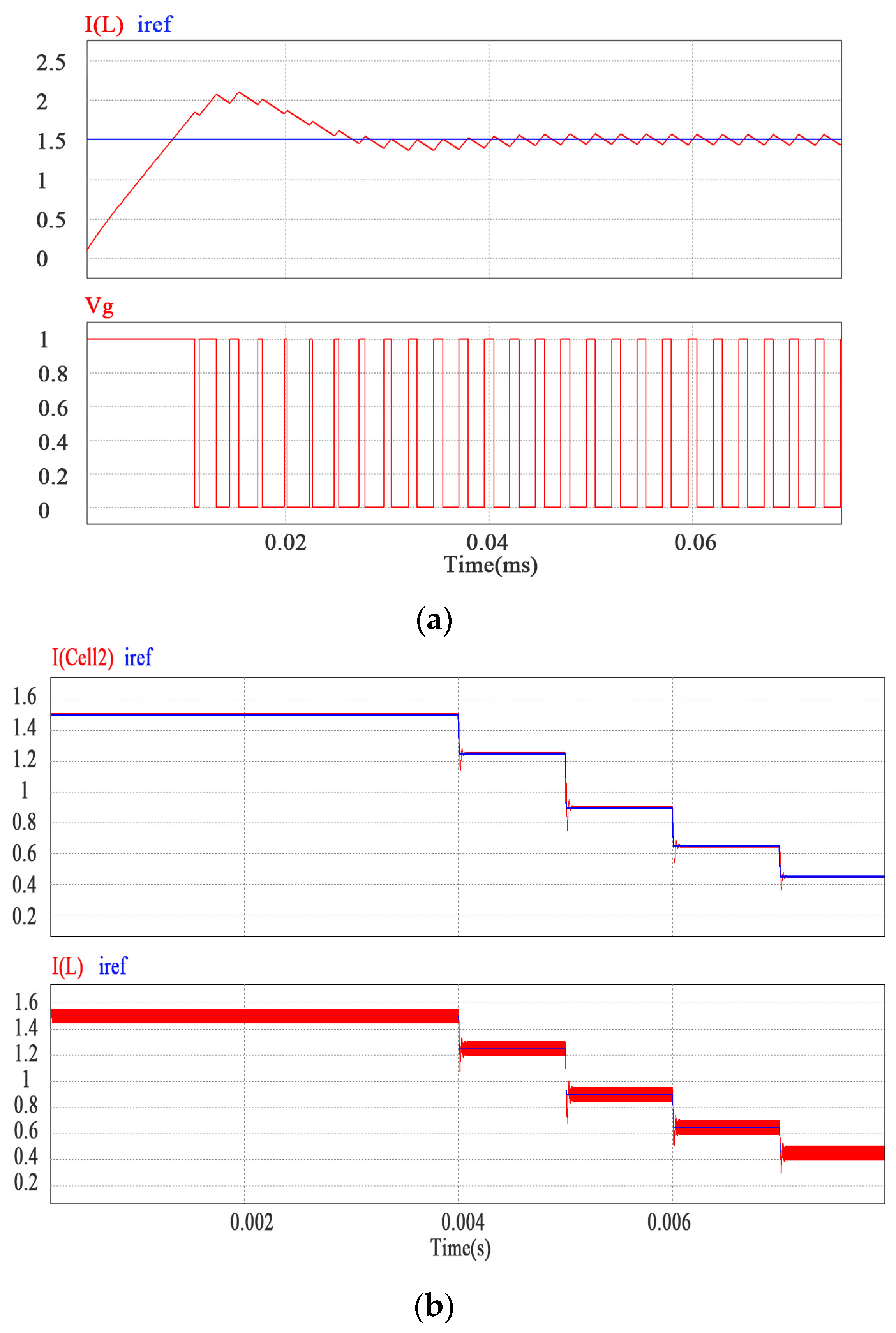
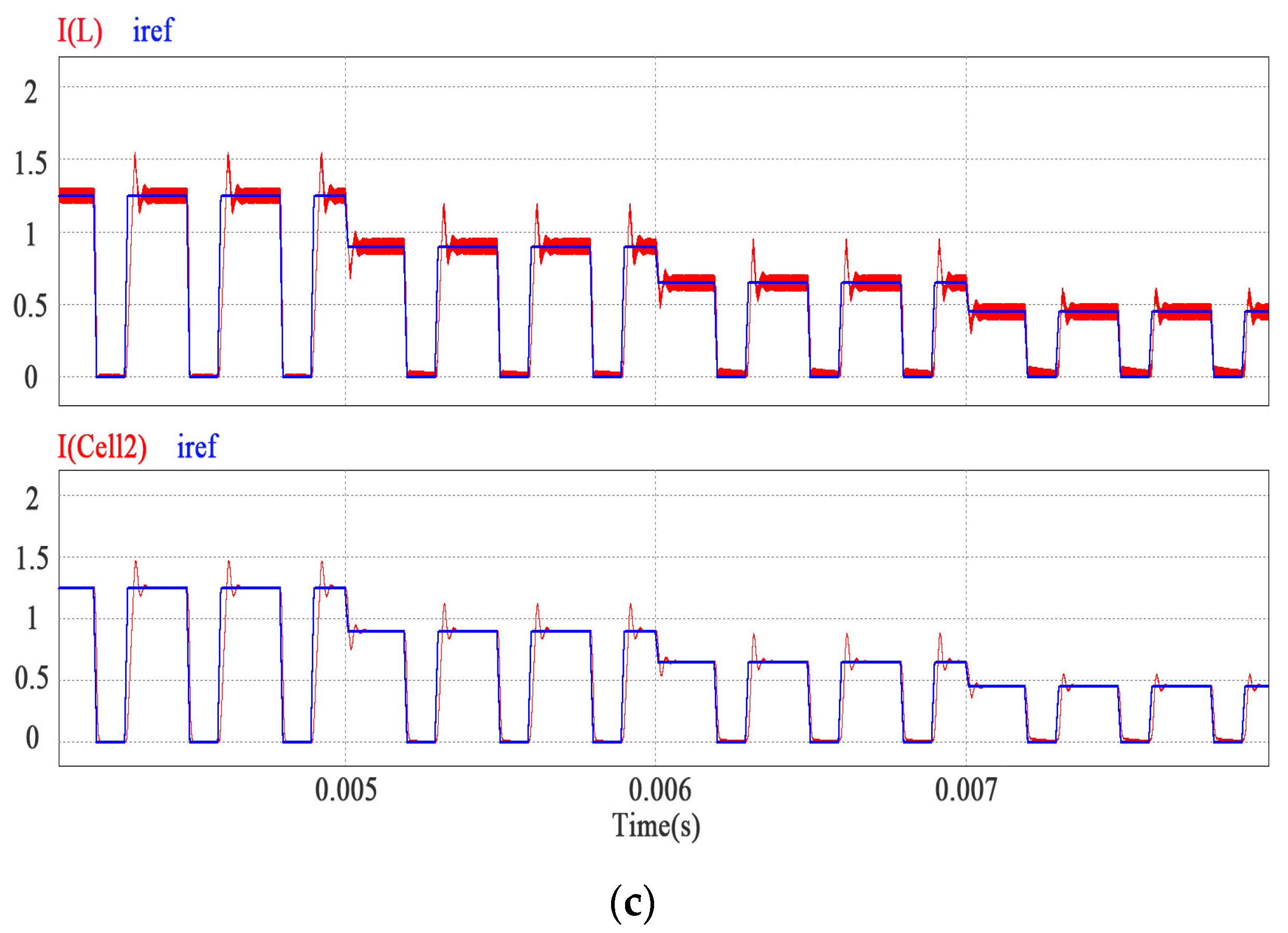
Based on the aforementioned controller design, a simulation is carried out to verify the proposed multistage pulse charging design by using simulation software PSIM. The simulation results are shown in
Figure 8. It is clear that the charging current/buck inductor current
iL can track the reference current
iref quickly and accurately through varying the duty cycle of buck converter’s gating signal with the PI controller. Multistage charging is illustrated in
Figure 8b. It is clear that the multistage charging algorithm is achieved and the whole charging procedure is divided into five stages according to different states of charge (SOC). The different charging currents of the different stages are optimized to reduce the charging time. The proposed multistage pulse charging is shown in
Figure 8c. The charging procedure is divided into several stages. The charging current for each stage is optimized first, and during each stage the pulse charging method is applied. The pulse charging frequency is reduced considerably to provide a clear concept of the proposed technique. Pulse charging fits the electrochemical reaction of a battery better and can prolong the cycle life and improve charging efficiency further.
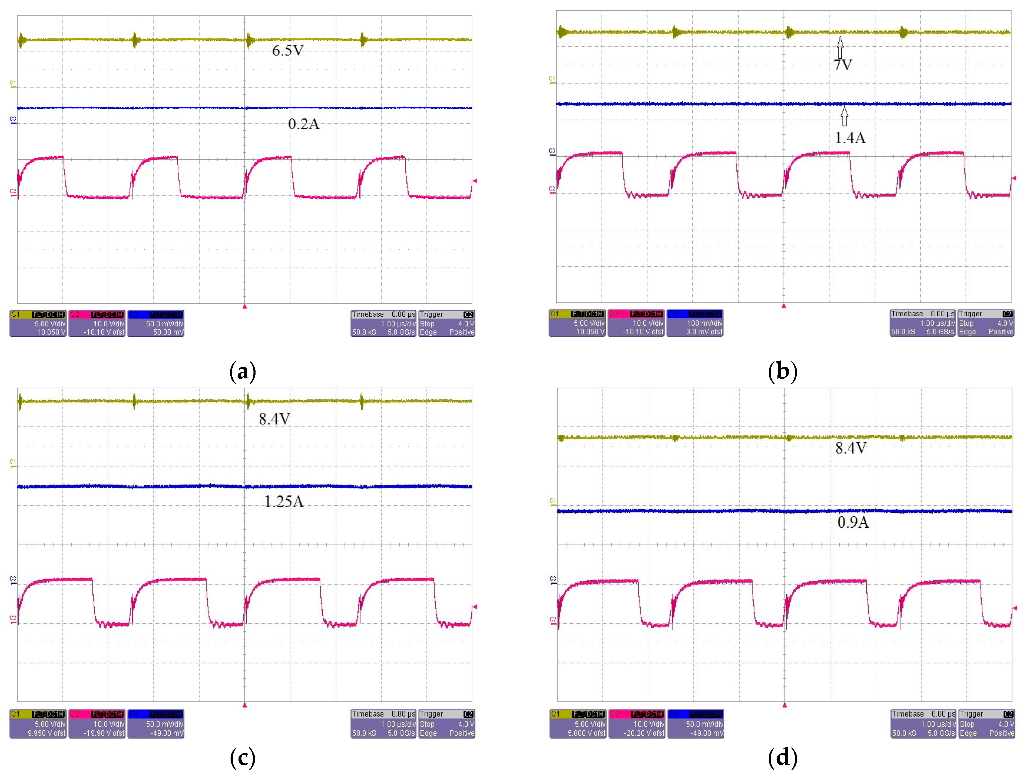
A laboratory prototype has been developed and tested. The experimental results are demonstrated in
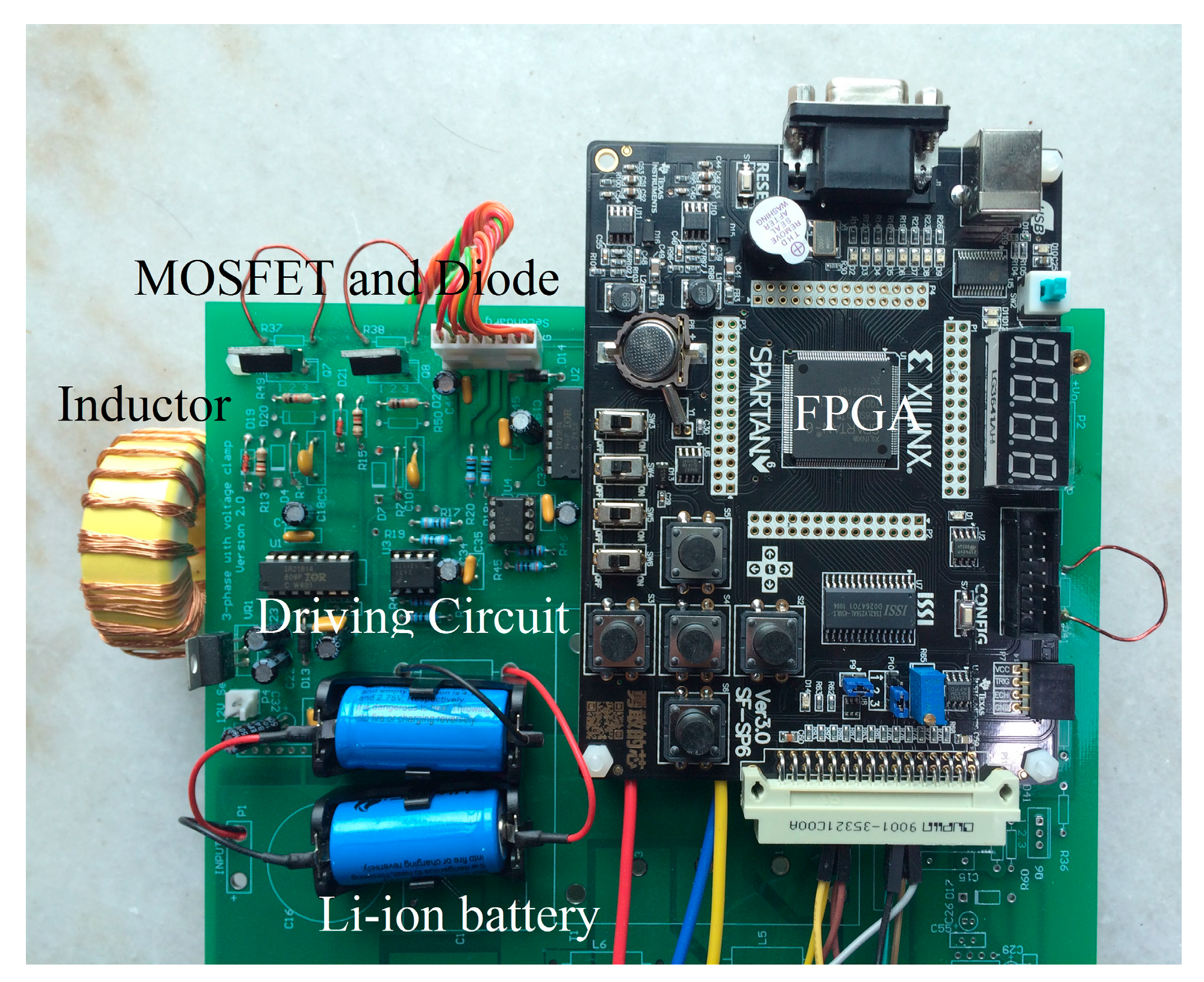
Figure 9. The picture of the experimental setup is shown in
Figure 10. The experimental details of the converter are as follows. Buck converter switch: MOSFET 6R125P; buck converter diode: IDH05SG60C, SiC schottky diodes; driver integrated circuits (ICs): IR2181; the Atlys circuit board based on a Xilinx Spartan-6 LX45 FPGA; buck converter inductor: ferrite core
L = 50 µH; output capacitor
C: a 22 µF electrolyte capacitor.
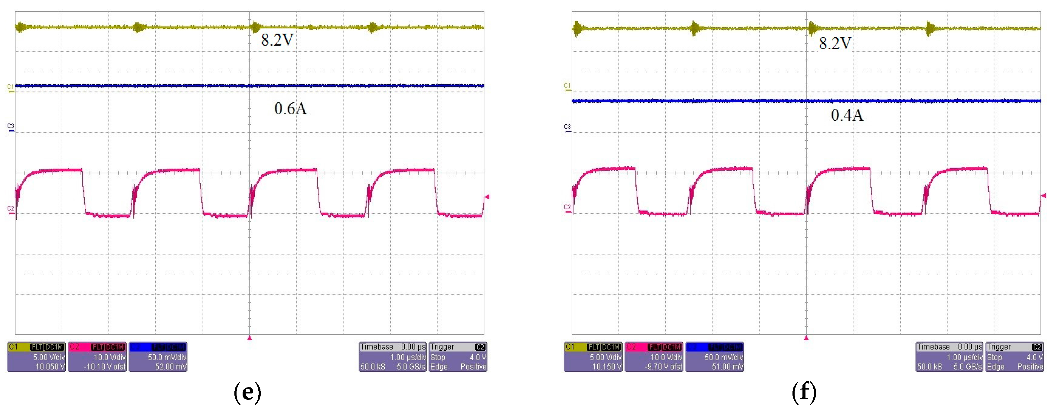
The experimental results clearly show that, for the proposed battery management system based on an FPGA based portable device and a designed PI controller, an advance charging algorithm such as the proposed multistage pulse charging is possible. The proposed charging process is divided into five stages and the obtained current setting values for each stage are 1.4 A, 1.25 A, 0.9 A, 0.6 A, and 0.4 A, respectively. For the pulse charging, the on-time charging mode will last 10 s, and then it will switch to off-time idle mode. While for the proposed smart charging structure as shown in
Figure 2, the smart selector under the control of FPGA will alternatively switch the channels between two battery packs. This mechanism can tremendously increase the charging efficiency while maintaining the advantage of pulse charging. The battery voltages are measured at the end of the idle mode of each battery pack, which is also precisely controlled by FPGA.
Figure 9 shows the whole charging procedure. Due to the proper design of the PI controller, the charging currents follow a multistage pulse charging profile with good stability. As shown by
Figure 9a, before the battery pack reaches 7.0 V, the charging current is as low as 0.2 A to extend the lifetime of the battery. The waveforms of
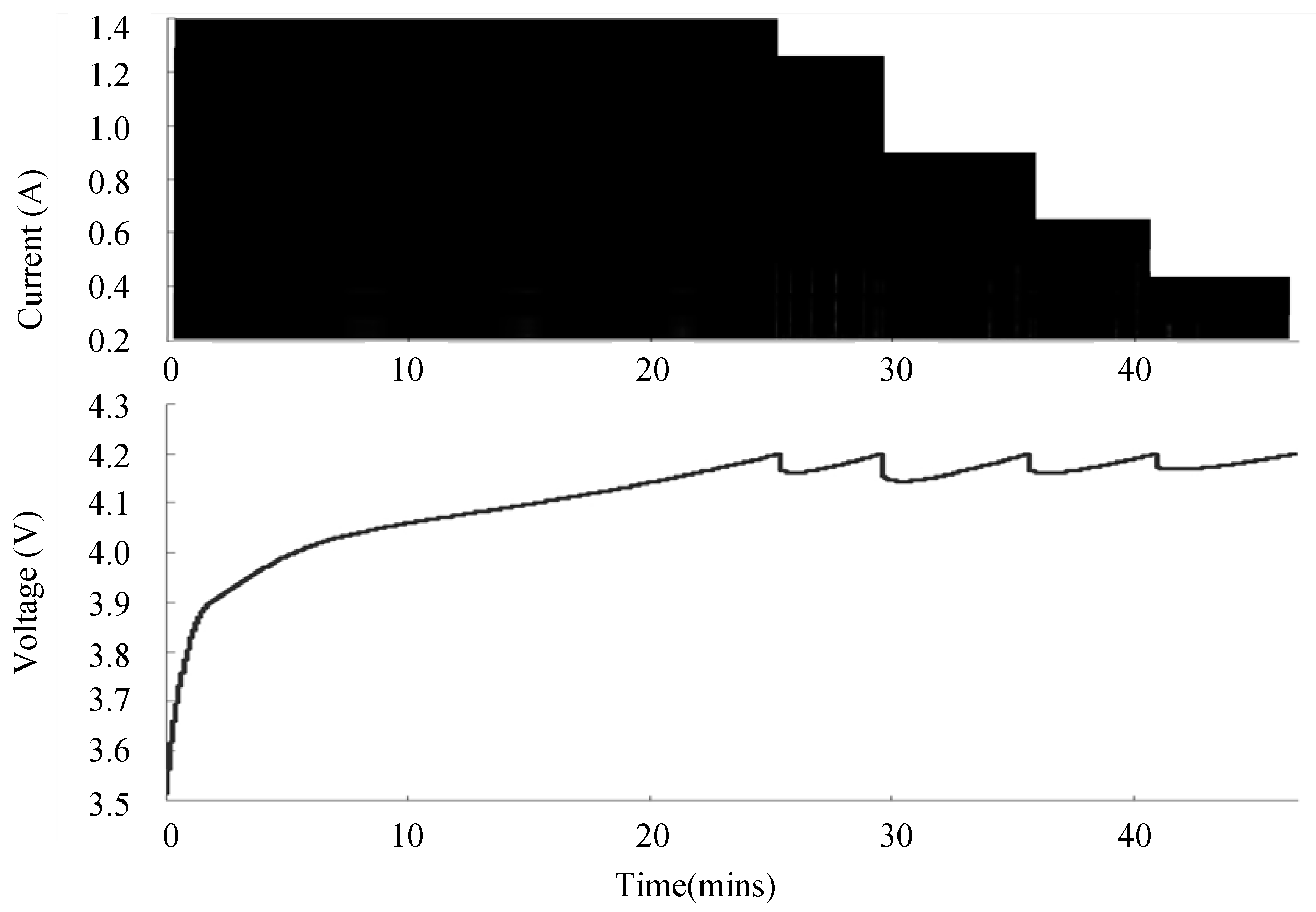
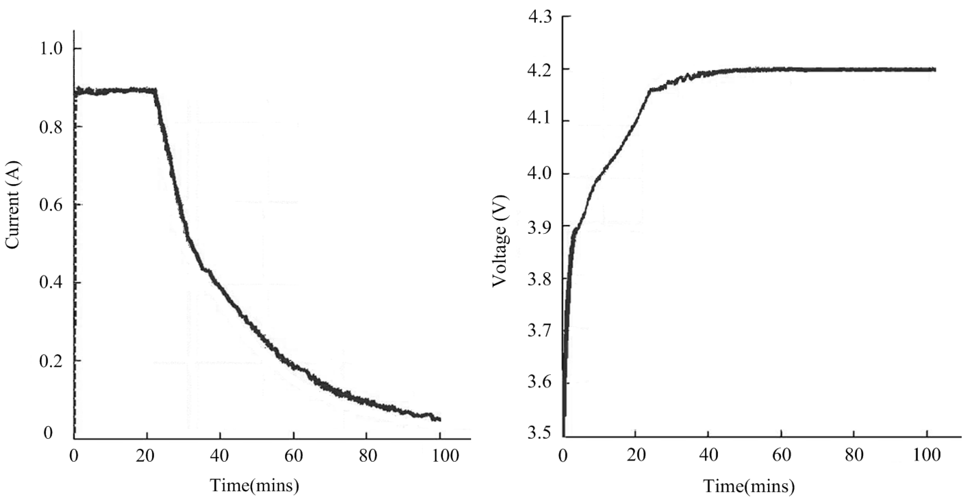
Figure 9b–f illustrate that the charging currents coincide with the designed values precisely. The measured current and voltage charging profiles of a single cell are given in
Figure 11. Each time the voltage across the battery pack reached the upper limit of 8.4 V (in a two cell battery pack), the charging procedure switched to next stage, as can be demonstrated by
Figure 4. After the five stages, the constant voltage charging stage starts until the charging current reaches the lower limit. It demonstrates that the proposed multistage pulse charging can be performed accurately on the designed FPGA based smart battery management system. The proposed multistage pulse charging algorithm is capable of charging the Li-ion batteries to 75% capacity within 40 min.
In order to verify the performance of the proposed charging method, a charging experiment using the conventional constant current/constant voltage (CC-CV) has also been carried out. The measured profiles of the charging current and the charging voltage have been illustrated in
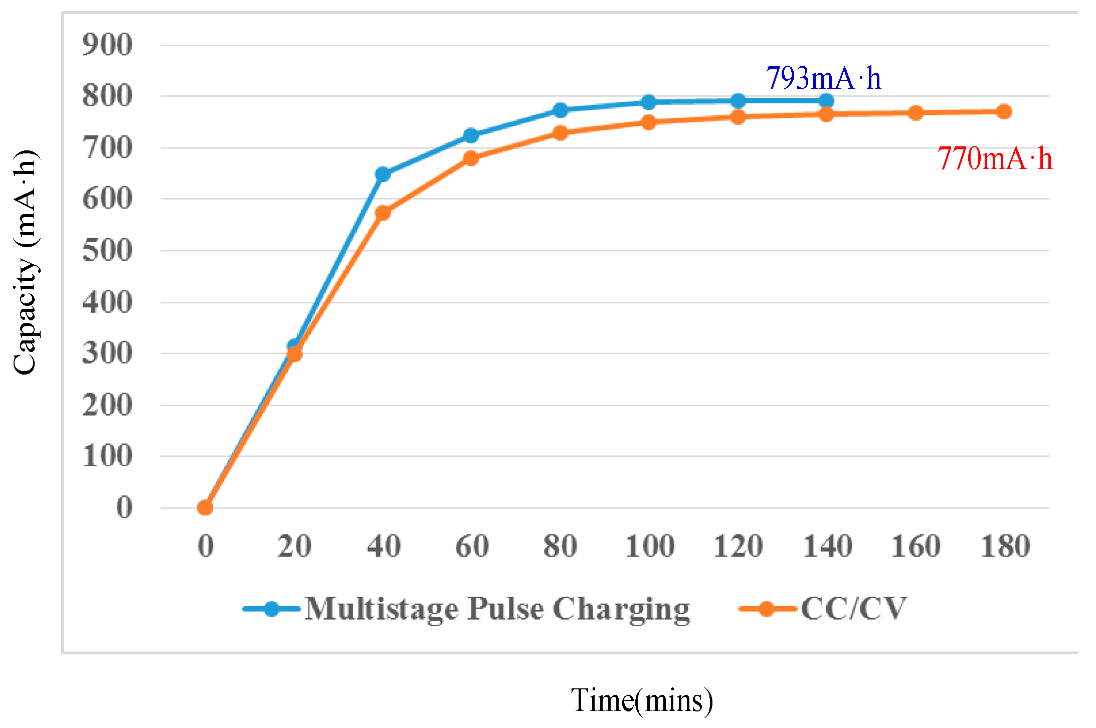
Figure 12. The profile of charging capacity of the battery implementing the proposed multistage pulse charging method and the CC/CV method have been shown in
Figure 13. The charging process of the proposed method terminated after 140 min, while the charging process of the CC/CV method terminated after 180 min, which is much longer than the proposed multistage pulse charging technique. The charging time of the CC/CV method has been significantly extended due to the CV charging period. Another reason is that the employed pulse charging current provides a rest period for the ions to diffuse and neutralize. Therefore a better charging effect can be achieved, especially at the later stage of charging. The charging capacities of the proposed method and the CC/CV method are 793 mA·h and 770 mA·h, respectively. The proposed method can obtain a better electrochemical reaction to get a larger storage capacity than the conventional CC/CV method.
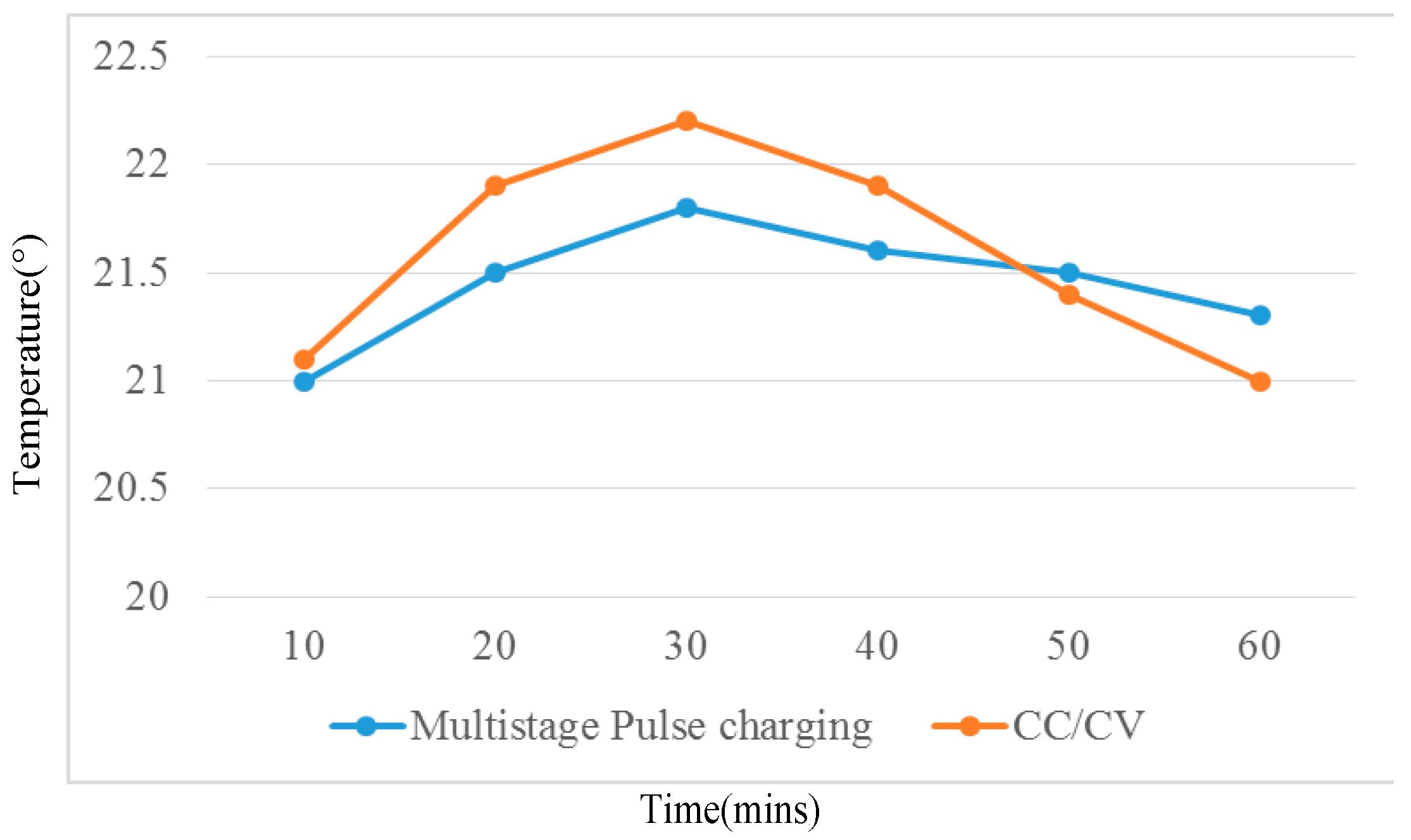
Figure 14 shows the measured temperature rise of the battery cell of both the proposed charging pattern and the CC/CV. It is easy to find that, for the main period of the charging time, the temperature rise of the proposed charging algorithm is lower than that of the conventional CC-CV method. As the temperature rise of the battery during charging is highly related to the cycle lifetime time of battery [
20], the proposed multistage pulse charging is expected to have a better cycle life performance. In [
11], the multistage charging algorithm has been demonstrated to provide 25% more cycle life than the CC/CV method. The proposed charging method combines the benefits of multistage charging and pulse charging. Therefore the experimental results verify that the proposed charging pattern can obtain better performance than the conventional CC/CV method in terms of charging efficiency and battery cycle life.
5. Conclusions
In this paper, a smart battery management system for FPGA based portable electronic devices is proposed. The four aspects of this concept, including (1) smart charging; (2) battery balancing; (3) smart discharging; and (4) safety operating, are elaborately analyzed. One novel charging algorithm, which combines the merits of multistage charging and pulse charging, is proposed to charge a Li-ion battery pack smartly. The simulation and experimental results are provided to validate the smart charging part of the proposed multistage pulse charging algorithm. Through comparison with the conventional CC-CV method, the charging efficiency of the proposed technique is shown to be better and able to prolong the cycle life time of battery. With this prototype, battery balancing, smart discharging, and safety operating experiments can be done in the future to further demonstrate the feasibility of proposed FPGA based smart battery management systems.

