Article

A Refined Self-Tuning Filter-Based Instantaneous Power Theory Algorithm for Indirect Current Controlled Three-Level Inverter-Based Shunt Active Power Filters under Non-sinusoidal Source Voltage Conditions

by
Yap Hoon
*,
Mohd Amran Mohd Radzi
,
Mohd Khair Hassan
and
Nashiren Farzilah Mailah
Department of Electrical and Electronic Engineering, Faculty of Engineering, Universiti Putra Malaysia, Serdang 43400, Selangor, Malaysia
*
Author to whom correspondence should be addressed.
Energies 2017, 10(3), 277; https://doi.org/10.3390/en10030277
Submission received: 10 January 2017 / Revised: 16 February 2017 / Accepted: 21 February 2017 / Published: 27 February 2017

Abstract

:
In this paper, a refined reference current generation algorithm based on instantaneous power (pq) theory is proposed, for operation of an indirect current controlled (ICC) three-level neutral-point diode clamped (NPC) inverter-based shunt active power filter (SAPF) under non-sinusoidal source voltage conditions. SAPF is recognized as one of the most effective solutions to current harmonics due to its flexibility in dealing with various power system conditions. As for its controller, pq theory has widely been applied to generate the desired reference current due to its simple implementation features. However, the conventional dependency on self-tuning filter (STF) in generating reference current has significantly limited mitigation performance of SAPF. Besides, the conventional STF-based pq theory algorithm is still considered to possess needless features which increase computational complexity. Furthermore, the conventional algorithm is mostly designed to suit operation of direct current controlled (DCC) SAPF which is incapable of handling switching ripples problems, thereby leading to inefficient mitigation performance. Therefore, three main improvements are performed which include replacement of STF with mathematical-based fundamental real power identifier, removal of redundant features, and generation of sinusoidal reference current. To validate effectiveness and feasibility of the proposed algorithm, simulation work in MATLAB-Simulink and laboratory test utilizing a TMS320F28335 digital signal processor (DSP) are performed. Both simulation and experimental findings demonstrate superiority of the proposed algorithm over the conventional algorithm.

1. Introduction

The widespread use of nonlinear loads has greatly degraded the quality of grid currents via generation of harmonic currents. Harmonic currents not only degrade overall system efficiency by worsening its power factor (PF) performance, but also cause other associated problems such as equipment overheating, failures of sensitive devices and capacitor blowing [1,2,3]. Therefore, it is compulsory to minimize harmonic levels of a power system.
In order to minimize harmonic contamination, various mitigation solutions such as passive filters, active power filters and hybrid filters have been proposed [4,5,6]. Nevertheless, the shunt-typed active power filter (SAPF) [4,5,6,7] is the most effective solution to current harmonics issues. Additionally, it is also capable of improving PF performances [7,8,9,10,11] by reducing reactive power burden on the power system, while mitigating harmonic currents. Generally, SAPF performs by injecting opposition current (simply known as injection current) back to the harmonic-polluted power system which allows the polluted source current to regain its sinusoidal characteristic with fundamental frequency.
Most research works on SAPF adopt a general two-level voltage source inverter (VSI) topology [12,13,14]. However, multilevel inverters which have been reported to be superior to conventional two-level inverters [15,16,17] in term of output voltage quality (less harmonic distortions), are acknowledged as better alternative. The harmonic contents of the generated output voltage can be reduced greatly by increasing the number of output voltage levels. However, for SAPF applications, the multilevel inverters employed are mostly limited to three-level inverters [2,18,19], as the high number of switching states and severe voltage imbalance problems of multilevel inverters (five-level and above) pose a great challenge in controller design. In three-level neutral-point diode clamped (NPC) inverter, voltage across the two splitting DC-link capacitors must equally be maintained at half of the overall DC-link voltage [2,17,19] so that a balanced injection current can be generated for effective cancellation of harmonic currents. Moreover, if the voltages are unbalanced, there is a high risk of premature switches failure due to over-stresses, and further increases of the total harmonics distortion (THD).
The effectiveness of SAPF is strictly dependent on how quickly and how accurately its reference current generation algorithm performs in generating the required reference current. Under balanced and sinusoidal source voltage conditions, various research works on this particular algorithm have been reported in the literature such as synchronous reference frame (SRF) [20,21,22], instantaneous power (pq) theory [2,23,24,25], dq-axis with Fourier (dqF) [26], fast Fourier transform (FFT) [27], synchronous detection (SD) [28,29] and artificial neural network (ANN) [30,31]. Nevertheless, among the available algorithms, pq theory algorithm provides the best advantages which include simple design, increased speed and fewer calculations, and thus makes it more likely to be implemented practically.
In real conditions, the main source voltages may be distorted (non-sinusoidal) and this greatly degrades the mitigation performance of SAPF which is commonly designed to operate under balanced and sinusoidal source voltage conditions. In this case, performance of the normal pq theory algorithm which applies low-pass filtering technique in extracting the required fundamental components [32] is poor and may even fail to function properly. Therefore, in order to ensure effective operation of SAPF, it is highly essential to properly consider the condition of the source voltages for the design of the reference current generation algorithm.
One of the effective approaches to deal with non-sinusoidal source voltages is by applying an optimization algorithm. In [33,34,35], an optimization algorithm is proposed to determine the required reference current by optimizing the operation of controller to meet THD limits set by IEEE Standard 519-1992 and other performance indices such as unity power factor. However, this work is limited to simulation studies only. IEEE Standard 519-1992 has now been revised as IEEE Standard 519-2014 [36]. Nevertheless, the THD limit of 5% for current is still valid in the latest IEEE standard and should be complied accordingly to ensure optimum power system performance. Next, another work in [37] has adopted a nonlinear optimization algorithm to obtain the best compromise between THD limits and unity power factor. However, the aforementioned optimization algorithms suffer from one major disadvantage where it depends on complex iterative approaches to solve the optimization problem. The strong dependency on an iterative approach can impose additional computational delay, which may restrict effectiveness of these control algorithms under dynamic-state conditions. As a result, the optimization algorithm proposed in [33,34,35,37] focused on harmonics mitigation under steady-state conditions only.
Another alternative is by using an adaptive notch filter (ANF) [38]. In [39], ANF is applied together with the pq theory approach to generate the required reference current for SAPF. The ANF is used to process the non-sinusoidal source voltage and distorted load current so that the fundamental voltage and current components can be extracted to compute the required fundamental average power. The fundamental average power is the main parameter involved in reference current generation. However, the performance of ANF strictly depends on its damping ratio and adaptation gain, which requires a fine tuning process to work effectively. Besides, the work is limited to simulation studies only.
A better alternative is by incorporating a self-tuning filter (STF) [7,40]. In the context of SRF-based reference current generation algorithms, the STF algorithm has been applied to enhance the ability of phase-locked loops (PLLs) to work under non-sinusoidal source voltages [41]. Like optimization algorithms, this algorithm is only evaluated under steady-state conditions. Another application of STF can be found in pq theory-based reference current generation algorithms, hereafter referred to as STF-based pq theory (STF-pq) algorithms [42]. In this case, the STF algorithm is applied to process the non-sinusoidal source voltage so that a purely sinusoidal reference voltage can be generated for proper synchronization purposes. Unlike an optimization algorithm which is commonly realized through a complex iterative computation process and an ANF approach which requires a fine tuning process, the STF-based algorithm which is simple and straightforward greatly reduces system requirements for practical implementation. Nevertheless, as compared to SRF-based algorithm, STF-pq theory algorithm is much more preferable as it does not require additional PLL elements for synchronization purposes. Most importantly, the STF-pq theory algorithm is reported in [42] to work effectively under both steady-state and dynamic-state conditions.
In the context of STF-pq theory algorithms, for effective generation of reference currents, another STF is commonly implemented to process the transformed set of load currents [40,42]. However, the performance of STF is fully dependent on its fixed gain value which is normally obtained via an empirical approach. Owing to the dependency on the fixed gain value, the STF is unable to perform satisfactorily in controlling nonlinear or time-varying systems, thus significantly affecting the accuracy of the generated reference current. Besides, the conventional STF-pq theory algorithm is still considered to possess redundant features which do not represent the basic requirements of reference current generation, thereby increasing the computational burden of the algorithm.
Another weakness of the conventional STF-pq theory algorithm is related to the characteristics of its generated reference current. To date, the conventional STF-pq theory algorithm still produces a non-sinusoidal reference current [7,40,42] and thus forces the SAPF to operate based on a direct current controlled (DCC) scheme [43,44,45]. From previous literature [45,46,47], it is revealed that the SAPF switching operation produces switching ripples which potentially degrade the THD value of the mitigated source current. However, the DCC scheme which generates pulse-width modulation (PWM) switching pulses based on error signals resulting from the difference between the measured injection current and its non-sinusoidal reference current counterpart [43,44,45], does not possess accurate information on the characteristics of the actual source current. Therefore, even if the source current is contaminated by switching ripples, DCC scheme is unable to alleviate the problems due to a lack of exact information. As a result, a mitigated source current of higher THD value is produced. Although the indirect current controlled (ICC) scheme which generates PWM switching pulses based on error signals resulting from the difference between the actual source current and its sinusoidal reference current counterpart [2,22,43,44] has been proven to overcome this weakness of the DCC scheme, there is still no work on STF-pq theory which has been conducted together with ICC scheme. In fact, the working principle of the conventional STF-pq theory algorithm has limited its application to DCC schemes.
Therefore, this paper presents a refined STF-pq theory algorithm which suits the operation of ICC-based SAPF in which a sinusoidal reference current is produced to govern the operation of the designated SAPF. Three aspects are identified for performing further refinements: fundamental component detection technique for generating a reference current, algorithm complexity and characteristics of the generated reference current. The design concept and effectiveness of the proposed algorithm are verified using MATLAB-Simulink. For performance comparison, a conventional STF-pq theory algorithm is developed too, and both algorithms are tested under highly nonlinear steady-state and dynamic-state conditions with a non-sinusoidal voltage supply. Moreover, a laboratory prototype is developed with the proposed algorithm downloaded in a digital signal processor (DSP) for further validation.
The rest of the paper is organized as follows: in Section 2, the proposed SAPF with control algorithms is described. Section 3 presents the details of the proposed reference current generation algorithm applied in the SAPF’s controller, highlighting the improvements and refinements performed. The simulation and experimental findings are presented, and critically discussed in Section 4 and Section 5 respectively, showing effectiveness of the proposed algorithm with equivalent comparison to the conventional algorithm. The paper ends with a brief conclusion in Section 6 by summarizing the significant contributions of this work.

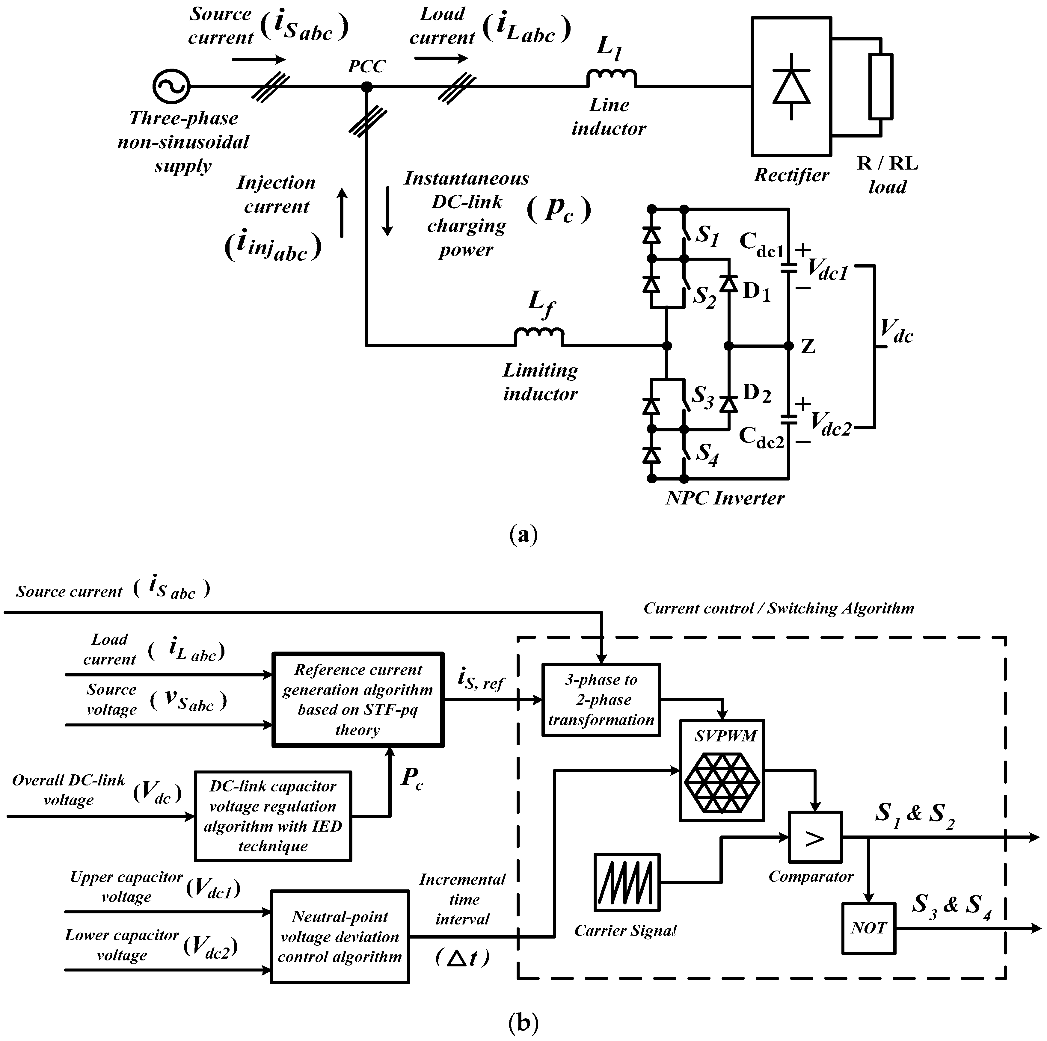
2. Shunt Active Power Filter (SAPF) with Control Algorithms

Circuit configuration of the proposed three-phase SAPF is shown in Figure 1. A three-level NPC inverter is employed as the SAPF and it is connected at point of common coupling (PCC) between the three-phase non-sinusoidal voltage supply and the nonlinear rectifier load. The rectifier is further connected to two types of loads: resistive (R) and inductive (RL) loads. Meanwhile, the SAPF’s controller consists of four control algorithms: reference current generation, DC-link capacitor voltage regulation, neutral-point voltage deviation control, and current control (switching) algorithms.
Nevertheless, the main focus of this paper is on reference current generation algorithm where a refined control algorithm is developed based on STF-pq theory. Meanwhile, DC-link capacitor voltage regulation algorithm with an inverted error deviation (IED) technique [3] is applied to consistently maintain the overall DC-link voltage at the desired level by delivering the required DC-link charging power P c , so that the required injection current i i n j can be accurately generated. Additionally, a neutral-point voltage deviation control algorithm [48,49,50] is applied to maintain voltage balance of splitting DC-link capacitors, by delivering the required incremental time interval Δ t with respect to the resulted instantaneous voltage error ( V d c 1 V d c 2 ) between the splitting DC-link capacitors. Finally, PWM switching pulses S 1 4 for controlling operation of SAPF are generated by a 25 kHz space vector PWM (SVPWM) current control algorithm [18,51,52].

3. Refined Self-Tuning Filter-Based Instantaneous Power (pq) Theory Algorithm

In order to clearly demonstrate the unique features of the proposed reference current generation algorithm, and at the same time, for showing proper comparisons, the particulars of the conventional algorithm which is developed based on STF-pq theory are first presented serving as a benchmark for improvement. Next, by referring to the conventional STF-pq theory algorithm, the proposed algorithm known as refined STF-pq theory algorithm is elaborated, highlighting the improvements made.

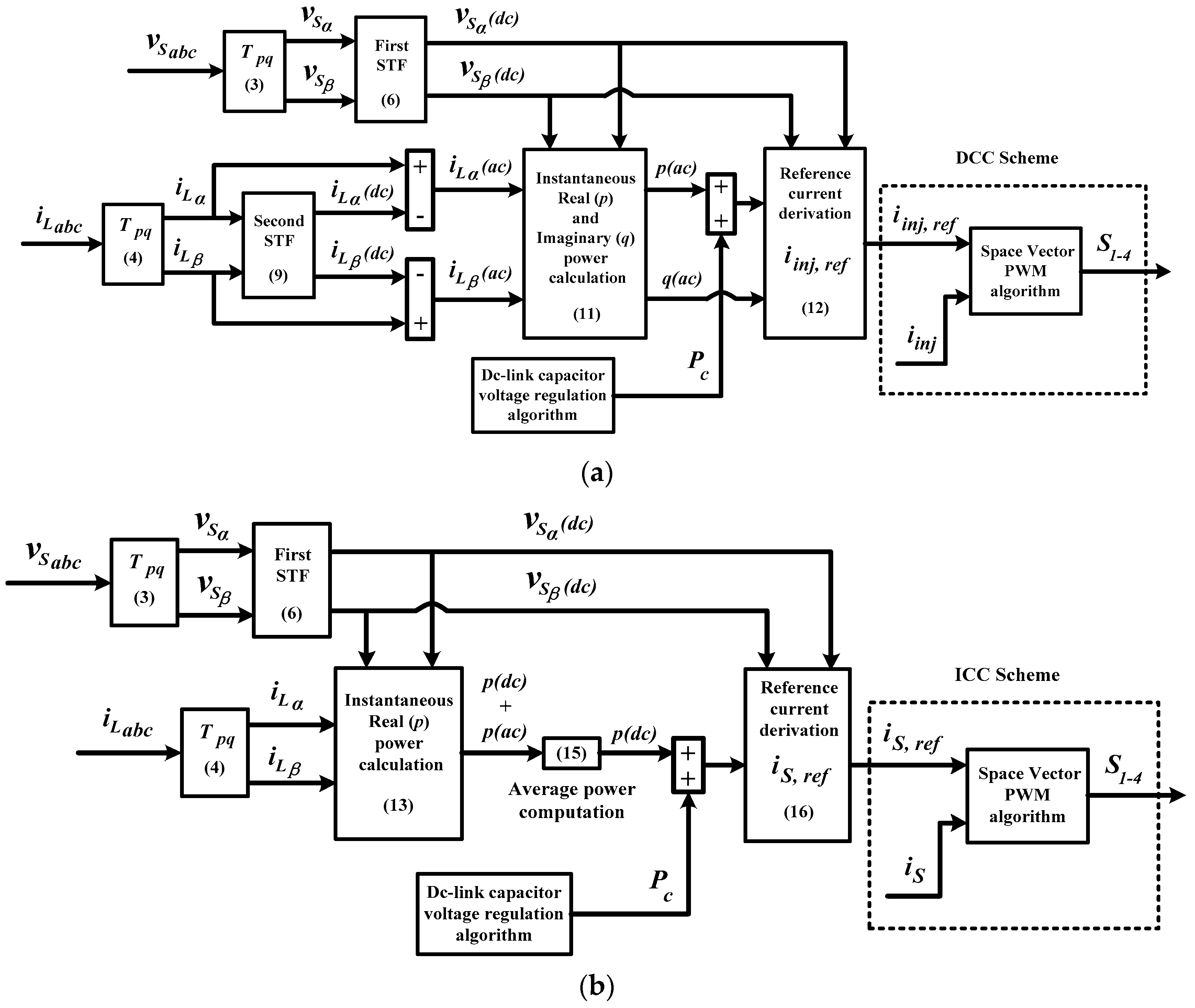
3.1. Conventional Self-Tuning Filter-Based Instantaneous Power (STF-pq) Theory Algorithm

The working principle of the conventional STF-pq theory algorithm is shown in Figure 2a. Generally, the reference current generation process is accomplished via a series of mathematical calculations of instantaneous power in a balanced three-phase system. The calculations are conducted in the α-β domain where all the required three-phase signals are converted into their respective two-phase α-β representation by using a transformation matrix T p q [32,53] which is expressed as:
T p q = 2 3 [ cos θ 1 ( t ) cos θ 3 ( t ) cos θ 2 ( t ) sin θ 1 ( t ) sin θ 3 ( t ) sin θ 2 ( t ) ]
where:
θ p h ( t ) = θ ( t ) + 2 π 3 ( p h 1 ) , p h = 1 , 2 , 3
and θ ( t ) is an angular arbitrary function which is considered as θ ( t ) = 0 .
Therefore, by applying T p q , the source voltage v S α β and load current i L α β in α-β domain are obtained according to the following approach:
[ v S α v S β ] = T p q [ v S a v S b v S c ]
[ i L α i L β ] = T p q [ i L a i L b i L c ]
where v S a , v S b , and v S c , and i L a , i L b , and i L c , are the three-phase source voltages and load currents respectively.
Under non-sinusoidal source voltage conditions, source voltage in α-β domain can actually be decomposed into dc and ac components as follows:
[ v S α v S β ] = [ v S α ( d c ) + v S α ( a c ) v S β ( d c ) + v S β ( a c ) ]
where v S α ( d c ) and v S α ( a c ) represent the fundamental (dc) and distorted (ac) components of source voltage in α domain respectively. Similar relation holds for source voltage in β domain, v S β ( d c ) and v S β ( a c ) .
In order to deal with non-sinusoidal source voltage conditions, a self-tuning filter (STF) is commonly applied to process the source voltage so that dc components of the source voltage can be extracted, serving as reference voltage to ensure in-phase operation of SAPF with the designated power system. In [7,40,42], the transfer function of STF for source voltage processing (after performing Laplace transformation) can be summarized as follows:
[ v S α ( d c ) ( s ) v S β ( d c ) ( s ) ] = K 1 s [ v S α ( s ) v S α ( d c ) ( s ) v S β ( s ) v S β ( d c ) ( s ) ] + 2 π f c s [ v S β ( d c ) ( s ) v S α ( d c ) ( s ) ]
where K 1 is a constant gain parameter and f c is the cutoff frequency. From [42], in order to achieve the best filtering performance of STF in extracting dc components of source voltage, K 1 and f c are commonly set at 100 and 50 Hz, respectively.
On the other hand, under the influences of nonlinear loads, the load current in α-β domain can also be decomposed into dc and ac components as follows:
[ i L α i L β ] = [ i L α ( d c ) + i L α ( a c ) i L β ( d c ) + i L β ( a c ) ]
where i L α ( d c ) and i L α ( a c ) represent the fundamental (dc) and distorted (ac) components of load current in α domain respectively. A similar relation holds for load current in β domain, i L β ( d c ) and i L β ( a c ) .
For generating a reference current, both i L α ( a c ) and i L β ( a c ) components are required. Generally, they are obtained by using indirect identification approach [54], where the dc components are first extracted by using a second STF followed by removal of the extracted dc components from the actual load current in α-β frame. This approach can be expressed as follows:
[ i L α ( a c ) i L β ( a c ) ] = [ i L α S T F ( i L α ( d c ) + i L α ( a c ) ) i L β S T F ( i L β ( d c ) + i L β ( a c ) ) ]
Meanwhile, the transfer function of the second STF for extracting the dc components of load currents can be expressed as follows:
[ i L α ( d c ) ( s ) i L β ( d c ) ( s ) ] = K 2 s [ i L α ( s ) i L α ( d c ) ( s ) i L β ( s ) i L β ( d c ) ( s ) ] + 2 π f c s [ i L β ( d c ) ( s ) i L α ( d c ) ( s ) ]
From [7,40,42], in order to achieve the best filtering performance of STF in extracting dc components of load currents, K 2 is commonly set at a value between the range of 20 to 80, and f c is fixed at 50 Hz.
Once the dc components of source voltage v S α ( d c ) and v S β ( d c ) , and ac components of load current i L α ( a c ) and i L β ( a c ) are computed, instantaneous complex power s is calculated as follows:
s = p ( a c ) + j q ( a c ) = v S α β ( d c ) i L α β ( a c ) * = ( v S α ( d c ) j v S β ( d c ) ) ( i L α ( a c ) + j i L β ( a c ) ) = ( v S α ( d c ) i L α ( a c ) + v S β ( d c ) i L β ( a c ) ) + j ( v S α ( d c ) i L β ( a c ) v S β ( d c ) i L α ( a c ) )
which can be rewritten as:
[ p ( a c ) q ( a c ) ] = [ v S α ( d c ) v S β ( d c ) v S β ( d c ) v S α ( d c ) ] [ i L α ( a c ) i L β ( a c ) ]
where p ( a c ) and q ( a c ) represent the distorted (ac) components of instantaneous real and imaginary powers, respectively.
After adding the DC-link charging power P c required for regulating the overall DC-link voltage of SAPF to the computed p ( a c ) (readers may refer to Figure 1b and Figure 2a), the required three-phase reference injection current i i n j , r e f is generated according to:
[ i i n j , r e f   a i i n j , r e f   b i i n j , r e f   c ] = T p q T det ( p q ) [ v S α ( d c ) v S β ( d c ) v S β ( d c ) v S α ( d c ) ] [ p ( a c ) + P c q ]
where det ( p q ) = v S α ( d c ) 2 + v S β ( d c ) 2 .
The non-sinusoidal i i n j , r e f forces the subsequent PWM switching pulses S 1 4 meant for controlling mitigation operation of SAPF, to be generated based on the DCC scheme which operates by requiring the measurement of the actual injection current i i n j .

3.2. Proposed Simplifications and Refinements

Despite the fact that the conventional STF-pq theory algorithm has been acknowledged as a straightforward and an effective algorithm in generating reference currents, it nevertheless has shortcomings and redundant elements which potentially degrade its performance. Therefore, additional refinements are performed, bringing about the development of refined STF-pq theory algorithm as shown in Figure 2b. Three noteworthy refinements are proposed and highlighted as follows:
(1)
A mathematical-based fundamental real power identifier is proposed to replace the second STF.
(2)
Reduction of the algorithm complexity through removal of imaginary power calculation.
(3)
Generation of sinusoidal reference source current instead of non-sinusoidal reference injection current.
The first refinement is proposed with the aim of overcoming the limitations of STF in extracting the dc components of the load current, which include a tedious gain tuning workload and significant delay in dc component detection. In order to implement the proposed refinement, the process for generating the required reference current needs to be changed. Previously, for generating reference current, STF is applied at earlier stage to extract the required dc components of load current before computing the instantaneous power. However, for the proposed refined STF-pq theory algorithm, all the dc components extraction processes (for reference current generation) are executed after computing the instantaneous power.
Mathematically, from (4) and (6), the instantaneous real power p in α-β domain is first computed as:
[ p ] = [ v S α ( d c ) v S β ( d c ) ] [ i L α i L β ]
Similarly, due to influences of nonlinear loads, the computed instantaneous real power p consists of p ( d c ) (fundamental) and p ( a c ) (distorted) components which can be expressed as follows:
[ p ] = [ p ( d c ) + p ( a c ) ]
Since the dc component of real power is equivalent to its average value, a mathematical-based fundamental real power identifier is proposed to compute the average value. The proposed fundamental real power identifier is given as:
p ( d c ) = P a v e r a g e = 1 T 0 T ( p ( d c ) + p ( a c ) ) d t
where P a v e r a g e is the average value of p and T is the period of the signal.
In this manner, the need of STF in extracting the dc components of load current is eliminated, thus removing the gain tuning workload as well as the possibility of inaccurate and inefficient dc components computation due to improper tuning.
Next, the second refinement is proposed, aimed at further reducing the algorithm complexity through removal of the imaginary power q calculation which is considered to be unnecessary in the context of reference current generation. In order to suit the working principle of the ICC scheme, the proposed algorithm is designed to produce a sinusoidal reference current. The generated sinusoidal reference current is expected to consist of only a fundamental sine component and to work in-phase with the source voltage. Hence, it is unnecessary to include imaginary power q calculation which represents the phase difference between the source current and source voltage, in the process of generating a reference current. In other words, computation using real power p alone is good enough to represent the sinusoidal characteristics and in-phase operation (with source voltage) of the resulted sinusoidal reference current.
Finally, the third refinement is proposed aimed at further reducing the higher THD value of the source current resulting from DCC-based operation. Therefore, operation of the conventional STF-PQ theory algorithm is modified to fulfill the requirements of the ICC scheme. In order to realize this modification, a reference current with sinusoidal characteristics must be generated. From (15), with the availability of p ( d c ) , the required P c is then added to regulate the overall DC-link voltage of SAPF, and as a result, the sinusoidal three-phase reference source current i S , r e f can now be generated according to:
[ i S , r e f   a i S , r e f   b i S , r e f   c ] = T p q T ( p ( d c ) + P c ) d e t ( p q ) [ v S α ( d c ) v S β ( d c ) ]
The sinusoidal i S , r e f enables the subsequent PWM switching pulses S 1 4 to be generated based on measurement of i S instead of i i n j . In other words, it changes the DCC-based operation to ICC-based operation. Unlike DCC-based operation, ICC-based operation which has been reported in [43,44,45,47] to possess exact information on switching ripples existing in the source current, allows accurate generation of reference currents to continuously control the operation of the SAPF and thus eliminates any unnecessary problem caused by SAPF switching operations.

4. Simulation Results

The proposed three-phase three-level NPC inverter-based SAPF utilizing the refined STF-pq theory algorithm is tested and evaluated in MATLAB-Simulink. Detailed simulation studies are performed under both steady-state and dynamic-state conditions which involve two cases of source voltages: in case 1, non-sinusoidal source voltage with only odd harmonics and in case 2, non-sinusoidal source voltage with both odd and even harmonics. For these two voltage cases, the source voltages applied are expressed as follows:
  • Case 1: Non-sinusoidal source voltage with only odd harmonics (THD = 28.11%)
    v S a = 326 sin ( ω t ) + 70 sin ( 3 ω t ) + 50 sin ( 5 ω t ) + 30 sin ( 7 ω t ) + 10 sin ( 9 ω t ) v S b = 326 sin ( ω t 120 ° ) + 70 sin ( 3 ( ω t 120 ° ) ) + 50 sin ( 5 ( ω t 120 ° ) ) + 30 sin ( 7 ( ω t 120 ° ) ) + 10 sin ( 9 ( ω t 120 ° ) ) v S c = 326 sin ( ω t + 120 ° ) + 70 sin ( 3 ( ω t + 120 ° ) ) + 50 sin ( 5 ( ω t + 120 ° ) ) + 30 sin ( 7 ( ω t + 120 ° ) ) + 10 sin ( 9 ( ω t + 120 ° ) )
  • Case 2: Non-sinusoidal source voltage with both odd and even harmonics (THD = 28.10%)
    v S a = 326 sin ( ω t ) + 8 sin ( 2 ω t ) + 70 sin ( 3 ω t ) + 4 sin ( 4 ω t ) + 50 sin ( 5 ω t ) + 2 sin ( 6 ω t ) + 30 sin ( 7 ω t ) v S b = 326 sin ( ω t 120 ° ) + 8 sin ( 2 ( ω t 120 ° ) ) + 70 sin ( 3 ( ω t 120 ° ) ) + 4 sin ( 4 ( ω t 120 ° ) ) + 50 sin ( 5 ( ω t 120 ° ) ) + 2 sin ( 6 ( ω t 120 ° ) ) + 30 sin ( 7 ( ω t 120 ° ) ) v S c = 326 sin ( ω t + 120 ° ) + 8 sin ( 2 ( ω t + 120 ° ) ) + 70 sin ( 3 ( ω t + 120 ° ) ) + 4 sin ( 4 ( ω t + 120 ° ) ) + 50 sin ( 5 ( ω t + 120 ° ) ) + 2 sin ( 6 ( ω t + 120 ° ) ) + 30 sin ( 7 ( ω t + 120 ° ) )
Meanwhile, two types of nonlinear loads are considered for the simulation studies. The first nonlinear load is constructed using a three-phase uncontrolled bridge rectifier feeding a 25 Ω resistor (resistive) and the second nonlinear load is developed using a similar rectifier feeding a series connected 50 Ω resistor and a 50 mH inductor (inductive). Moreover, the conventional STF-pq algorithm is also tested for comparison purposes. The key specifications of the proposed SAPF are summarized in Table 1.
Under steady-state conditions, each reference current generation algorithm is evaluated in term of current harmonics mitigation performance (THD value) demonstrated by SAPF. Meanwhile, under dynamic-state conditions, each reference current generation algorithm is evaluated in term of dynamic response (response time) demonstrated by SAPF in current harmonics mitigation. For this analysis, two dynamic-state conditions are created by changing the nonlinear loads from resistive to inductive and inductive to resistive, respectively.

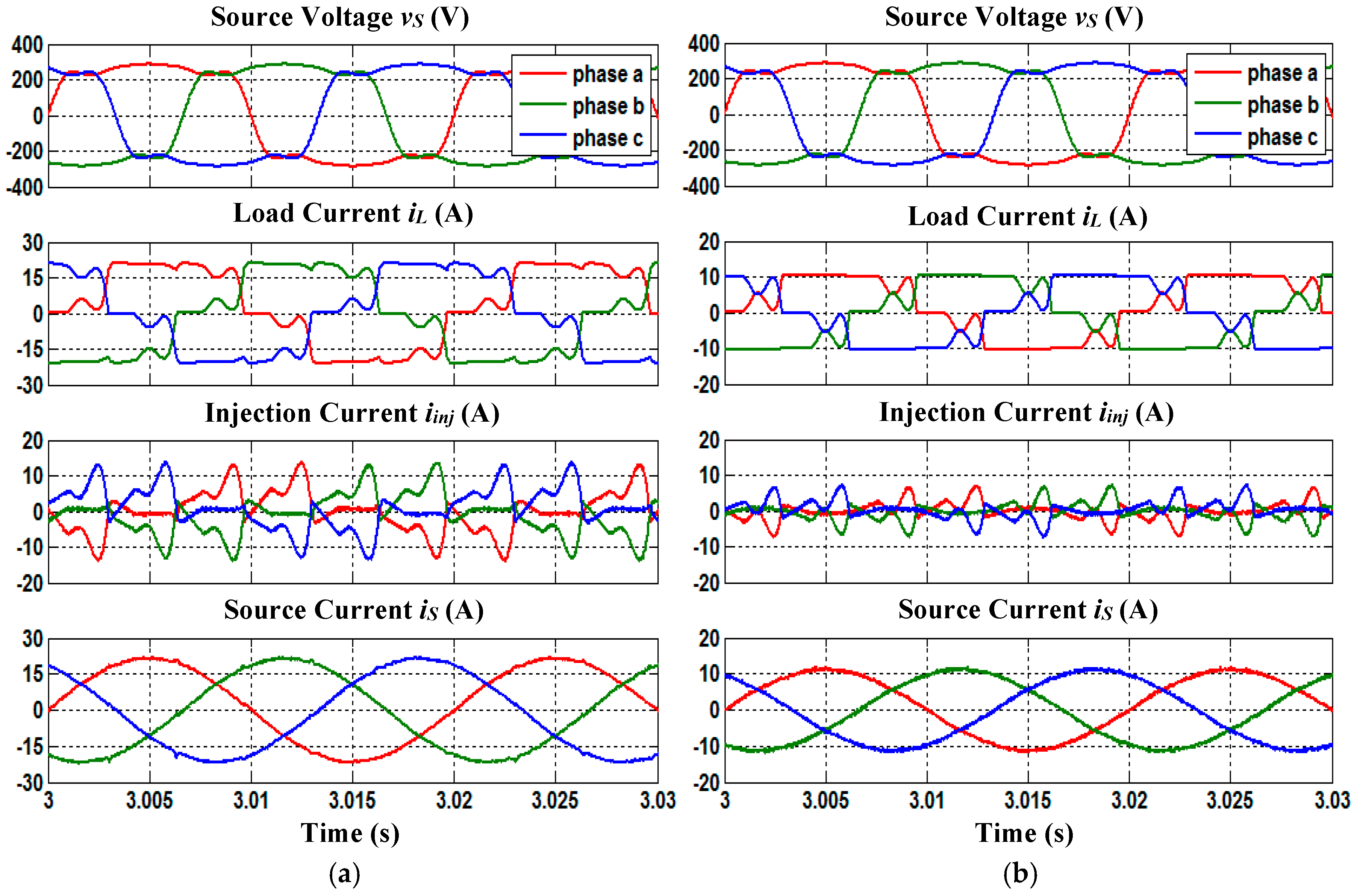
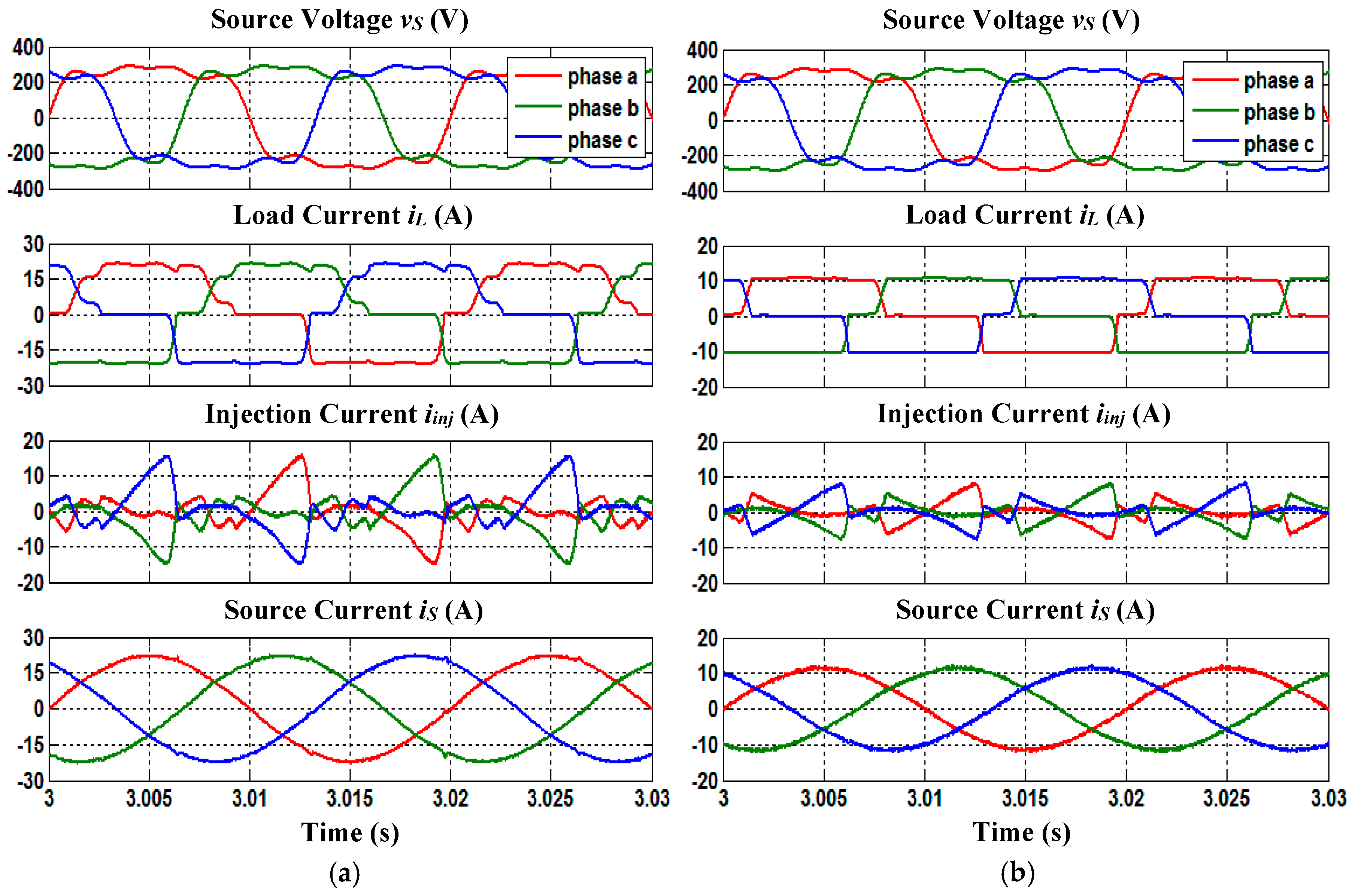
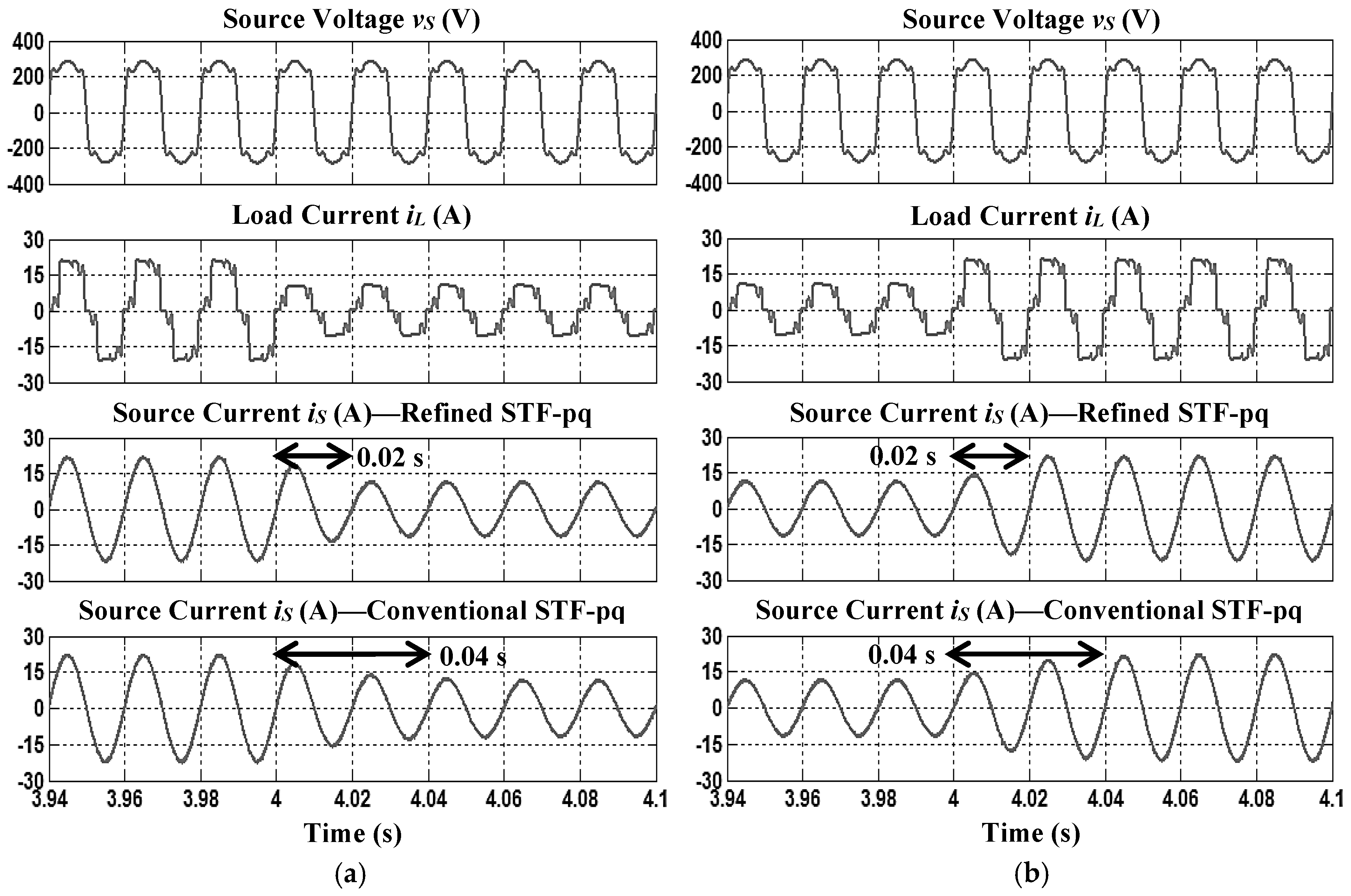
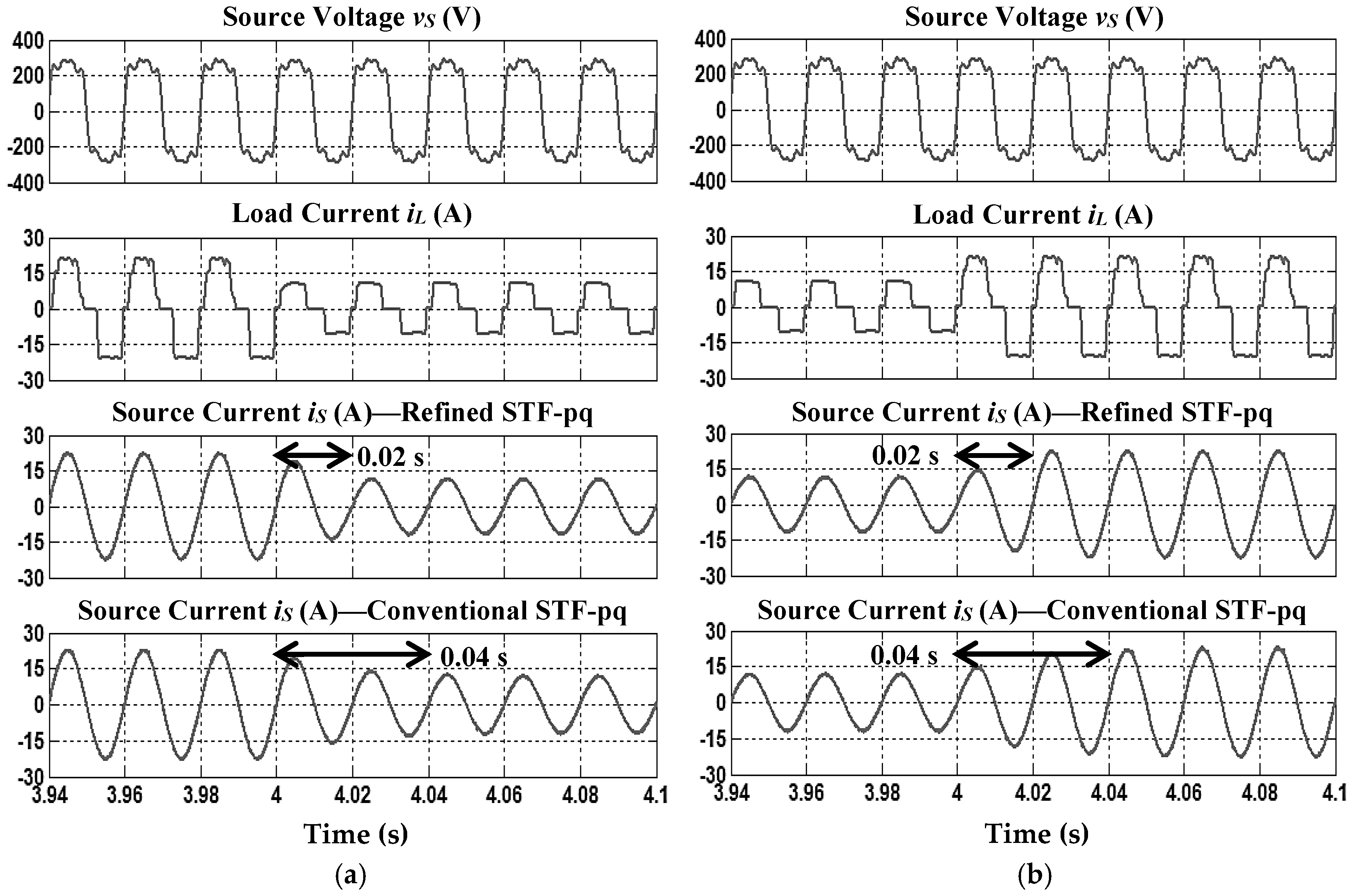
4.1. Steady-State Condition Analysis

For the case 1 non-sinusoidal source voltage condition, steady-state simulation waveforms of SAPF utilizing the refined STF-pq theory algorithm which includes three-phase source voltage v S , load current i L , injection current i i n j , and source current i S , for resistive and inductive loads are shown in Figure 3. Meanwhile, for the case 2 non-sinusoidal source voltage condition, the steady-state simulation waveforms are shown in Figure 4. The corresponding THD values of source current i S resulted from SAPF utilizing each reference current generation algorithm obtained for case 1 and case 2 non-sinusoidal source voltage conditions, are recorded in Table 2 and Table 3, respectively.
From the findings, it is obvious that under both non-sinusoidal source voltage conditions, SAPF utilizing each reference current generation algorithm has successfully removed the harmonic currents generated by both nonlinear loads, resulting in THD values of far below 5%, complying with the limit set by IEEE Standard 519-2014 [36]. However, SAPF utilizing the refined STF-pq theory algorithm performs outstandingly by achieving THD values of 0.09%–0.33% lower than conventional STF-pq theory algorithm, thereby showing the superiority of the proposed algorithm over the conventional algorithm under steady-state conditions. Furthermore, it can be observed that the mitigated source current i S is working in phase with the source voltage v S for all nonlinear loads, thereby improving the power factor to almost unity.

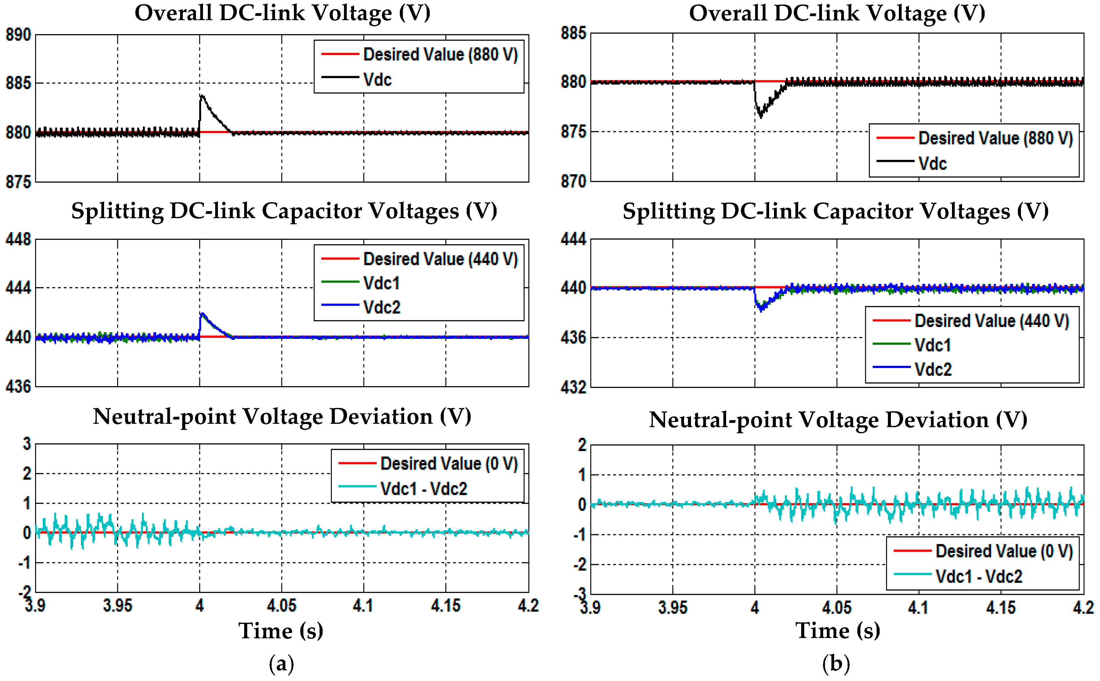
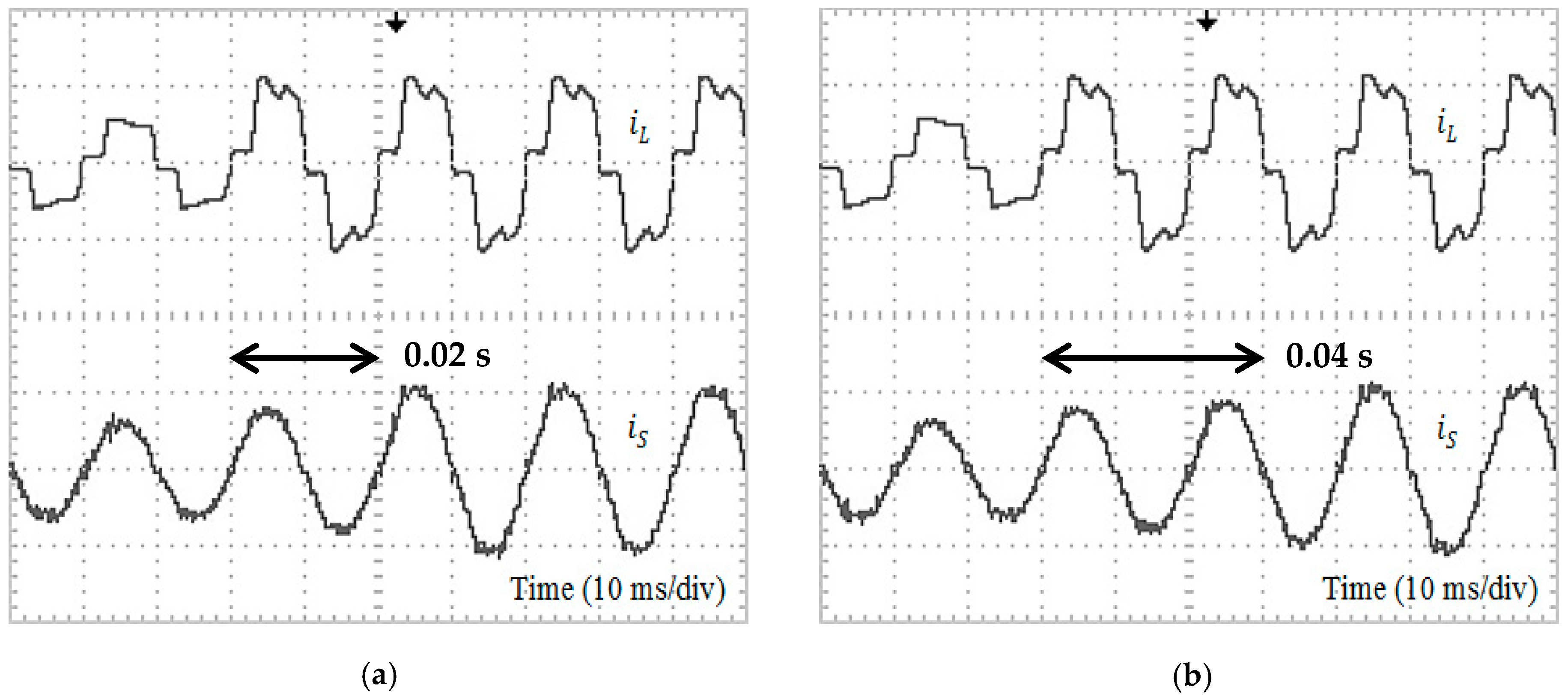
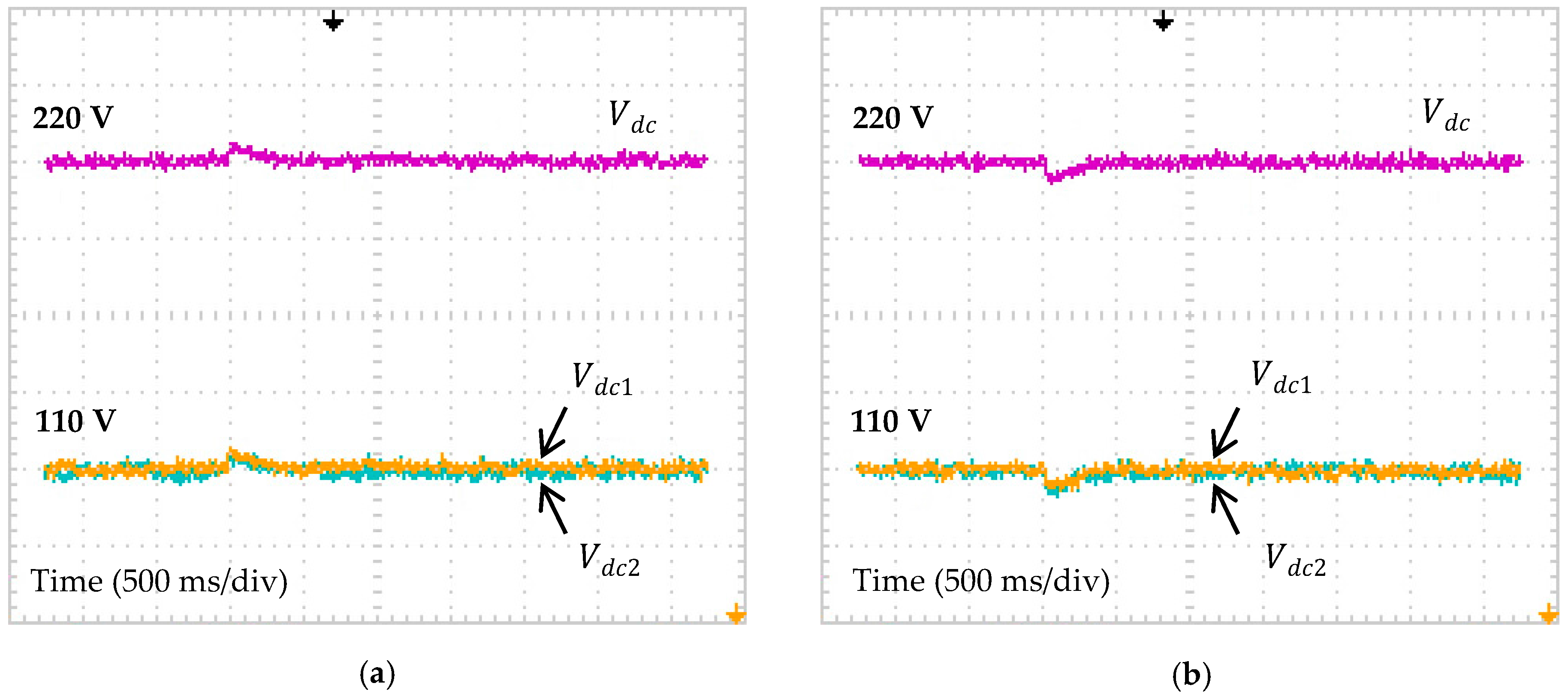
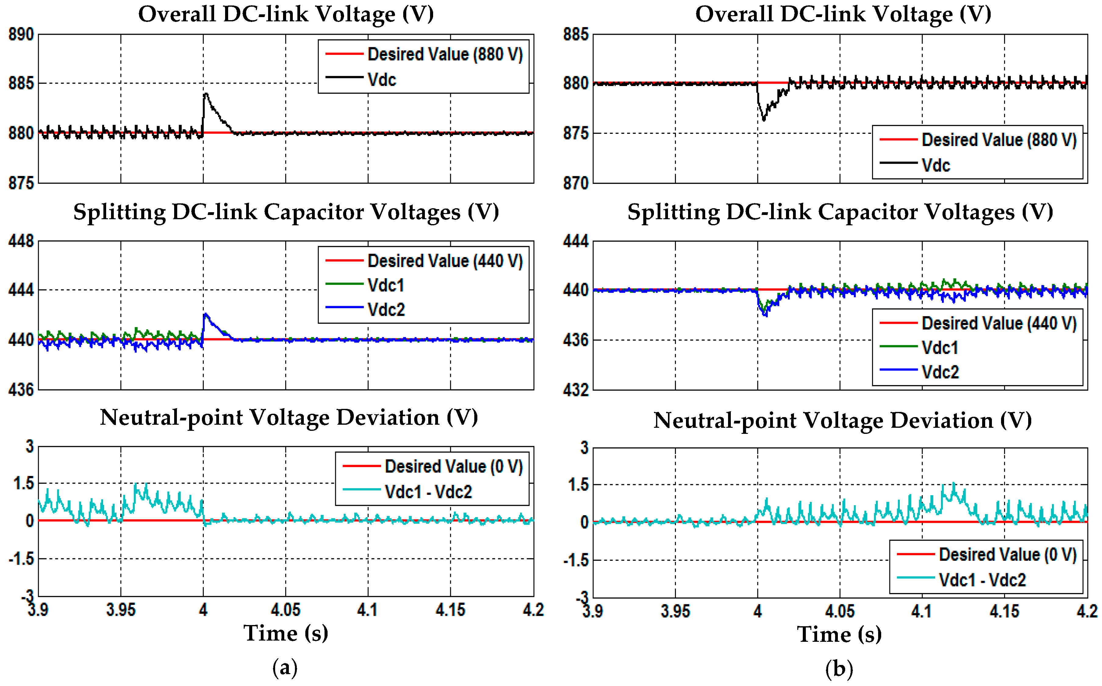
4.2. Dynamic-State Condition Analysis

For case 1 non-sinusoidal source voltage conditions, dynamic behaviour demonstrated by each reference current generation algorithm under dynamic-state conditions of resistive to inductive and inductive to resistive is shown in Figure 5. Meanwhile, for case 2 non-sinusoidal source voltage condition, the dynamic behaviour of each reference current generation algorithm in mitigating harmonic currents is shown in Figure 6. Based on Figure 5 and Figure 6, it is clear that for both dynamic-state conditions, regardless of the non-sinusoidal source voltage case (1 or 2) the refined STF-pq theory algorithm shows the best performance with a response time of 0.02 s. Meanwhile, the conventional STF-pq theory algorithm performs poorly with a response time of 0.04 s. In other words, SAPF utilizing the proposed algorithm shows superior dynamic performance by achieving a response time two times faster than the conventional algorithm.
In addition, other important aspects of three-level NPC inverter-based SAPF which include overall DC-link voltage regulation, voltage balancing of splitting DC-link capacitors and neutral-point voltage deviation control are thoroughly investigated to further verify effectiveness of the proposed SAPF. Based on Figure 7 and Figure 8, under both non-sinusoidal source voltage conditions, it is clear that all DC-link capacitor voltages are properly regulated and maintained at the desired value. Moreover, voltages across both splitting DC-link capacitors ( V d c 1 and V d c 2 ) are equally maintained at half of the overall DC-link voltage V d c with minimal neutral-point voltage deviation and thus confirming the effectiveness DC-link capacitor voltage regulation and neutral-point voltage deviation control algorithms applied in the proposed SAPF.
Based on all the simulation results obtained in both steady-state and dynamic-state conditions, it is clear that the refined STF-pq theory algorithm provides the best current harmonics mitigation performance with low THD and fast response time. On the other hand, the conventional STF-pq theory algorithm which has widely been reported in the literature performs well under steady-state conditions (THD < 5%). However, under dynamic-state conditions, the conventional STF-pq theory algorithm is unable to track and respond fast enough to rapid nonlinear load changes.

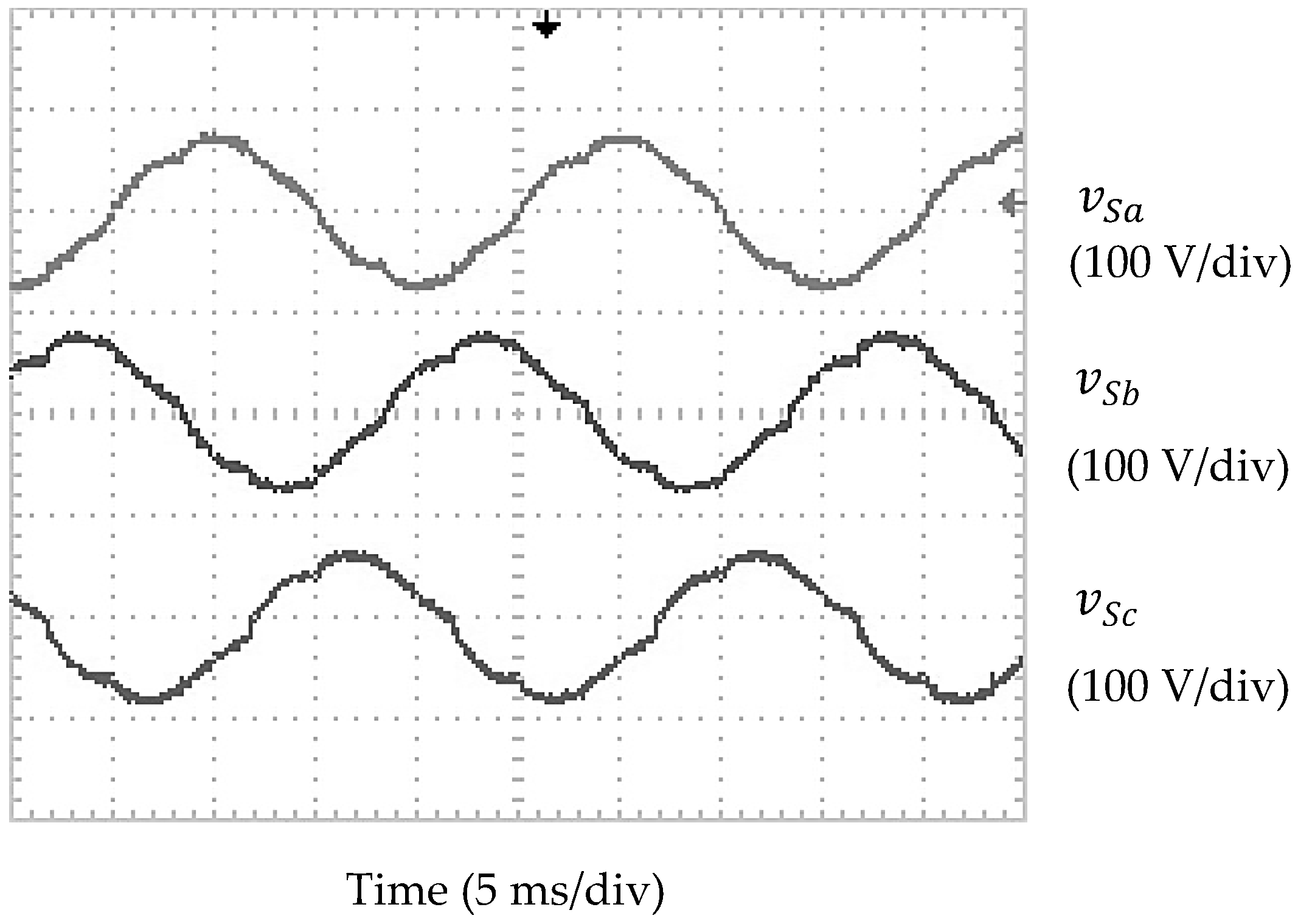
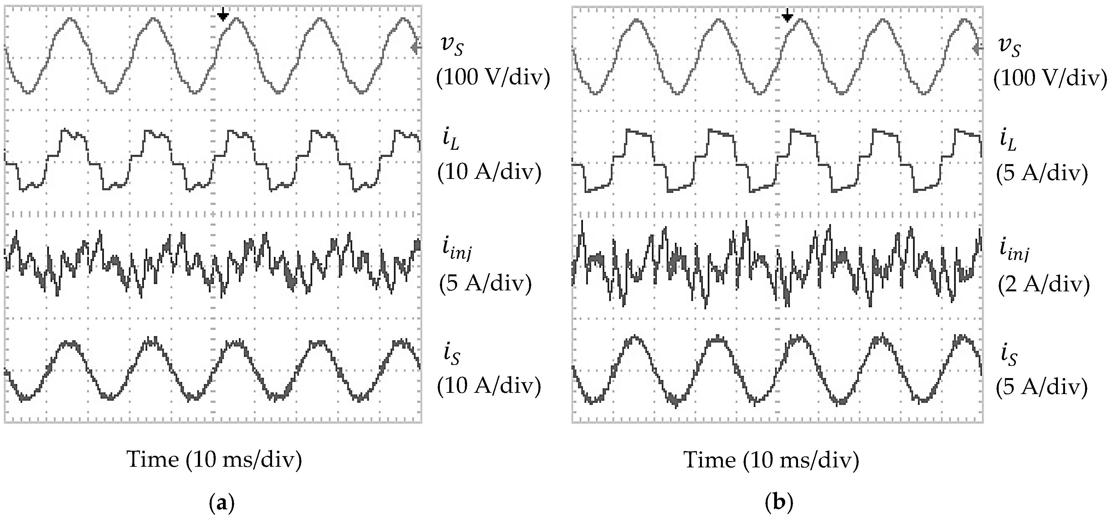
5. Experimental Verification

A laboratory prototype was developed to validate practically the performance of the refined STF-pq theory algorithm. The experimental setup for the proposed SAPF is shown in Figure 9. For experimental testing, a three-phase, 50 Hz, 100 Vrms, non-sinusoidal voltage source is considered, and it is supplied from a three-phase practical transformer. The waveforms of source voltage applied in experimental testing are shown in Figure 10. It can be seen that the source voltage is balanced but non-sinusoidal with THD = 6.91%. Meanwhile, the desired overall DC-link reference voltage is set at 220 V. Furthermore, a TMS320F28335 DSP board is configured and programmed to perform all control algorithms of the SAPF and to generate the desired PWM switching pulses for the three-phase three-level NPC inverter. A similar analysis to what was performed in the simulation work is considered for the experimental analysis.
The steady-state experimental waveforms (phase A) of SAPF utilizing the refined STF-pq theory algorithm which includes source voltage v S , load current i L , injection current i i n j , and source current i S , for resistive and inductive loads are shown in Figure 11. Meanwhile, the THD values of source current i S in all phases resulted from SAPF utilizing each reference current generation algorithm are recorded in Table 4. On the other hand, Figure 12 and Figure 13 show the dynamic behaviour of SAPF utilizing each reference current generation algorithm in current harmonics mitigation for dynamic-state conditions of resistive to inductive and inductive to resistive respectively.
The findings confirm that under non-sinusoidal source voltage condition, SAPF utilizing each reference current generation algorithm has successfully removed the current harmonics generated by both nonlinear loads, resulting in THD values of below 5%. However, SAPF utilizing the refined STF-pq theory algorithm performs outstandingly by achieving the lowest THD values, which is 0.44%–0.70% lower than the conventional STF-pq theory algorithm. Moreover, the mitigated source current i S seems to work in phase with the source voltage v S and thus achieving almost unity power factor.
Most importantly, by using the refined STF-pq theory algorithm, the response time of two cycles (0.04 s) in current harmonics mitigation which is achieved previously by using the conventional STF-pq theory algorithm is now significantly reduced to one cycle (0.02 s), thus confirming the superiority of the proposed algorithm over the conventional algorithm under dynamic-state conditions.
Furthermore, Figure 14 shows the experimental result obtained for the overall DC-link voltage V d c , and the splitting DC-link capacitor voltages ( V d c 1 and V d c 2 ), for dynamic-state conditions of resistive to inductive and inductive to resistive. The findings show that all the DC-link voltages ( V d c , V d c 1 and V d c 2 ) of the proposed SAPF are properly controlled at the desired value for both dynamic-state conditions. Moreover, voltages across both splitting DC-link capacitors ( V d c 1 and V d c 2 ) are successfully maintained at half of the overall DC-link voltage V d c with minimal deviation, hence, confirming the effectiveness of the DC-link capacitor voltage regulation and neutral-point voltage deviation control algorithms applied in the proposed SAPF.
Based on all the simulation and experimental findings in both steady-state and dynamic-state conditions, the improvements achieved by the refined STF-pq theory algorithm has clearly revealed significant roles of applying mathematical-based fundamental real power identifier, simplifying the algorithm complexity, and generation of sinusoidal reference current to suit ICC-based operation. The implementation of the proposed algorithm has significantly improved the mitigation performance of the proposed SAPF. In addition, the effective control of all the DC-link voltages at their respective desired values together with minimal neutral-point voltage deviation has further verified the design concept and the effectiveness of the proposed SAPF in current harmonics mitigation.

6. Conclusions

This paper has successfully demonstrated a refined reference current generation algorithm based on STF-pq theory for a three-phase three-level NPC inverter-based SAPF. In this algorithm, three main refinements are performed which include incorporation of a mathematical-based fundamental real power identifier, simplification of the algorithm complexity and generation of a sinusoidal reference current. Comprehensive analyses in both steady-state and dynamic-state conditions are conducted to evaluate the performance of the proposed algorithm. Simulation work reveals that utilization of the proposed algorithm improves the mitigation performance of SAPF during steady-state conditions by achieving low THD values. Moreover, a significant improvement can be observed during dynamic-state conditions where the proposed algorithm performs successfully with fast response times. The proposed algorithm is not limited to inverter-based SAPF with aspecific type of load or under specific non-sinusoidal source voltage conditions. In fact, it is proven to work effectively with various types of nonlinear loads and under highly harmonic-distorted non-sinusoidal source voltages. Furthermore, the experimental findings have confirmed the effectiveness of the proposed algorithm in both steady-state and dynamic-state conditions as shown in simulation work. The low THD value and fast response time clearly show the advantages of the refined STF-pq theory algorithm over the conventional STF-pq theory algorithm, especially in dealing with dynamic-state conditions.

Author Contributions

Yap Hoon designed and developed the main parts of the research work which includes simulation model, experimental setup, and analyses of the results obtained. Yap Hoon was also mainly responsible for manuscript preparation. Mohd Amran Mohd Radzi contributed in simulation, experimental, and manuscript preparation. Mohd Khair Hassan and Nashiren Farzilah Mailah were in charged in verifying the work and have actively contributed in finalizing the manuscript.

Conflicts of Interest

The authors declare no potential conflict of interest.

References

  1. Kale, M.; Ozdemir, E. An adaptive hysteresis band current controller for shunt active power filter. Electr. Power Syst. Res. 2005, 73, 113–119. [Google Scholar] [CrossRef]
  2. Hoon, Y.; Radzi, M.A.M.; Hassan, M.K.; Mailah, N.F. Enhanced instantaneous power theory with average algorithm for indirect current controlled three-level inverter-based shunt active power filter under dynamic state conditions. Math. Probl. Eng. 2016, 2016, 9682512. [Google Scholar] [CrossRef]
  3. Hoon, Y.; Radzi, M.A.M.; Hassan, M.K.; Mailah, N.F. DC-link capacitor voltage regulation for three-phase three-level inverter-based shunt active power filter with inverted error deviation control. Energies 2016, 9, 533. [Google Scholar] [CrossRef]
  4. Akagi, H. Active harmonic filters. Proc. IEEE 2005, 93, 2128–2141. [Google Scholar] [CrossRef]
  5. El-Habrouk, M.; Darwish, M.K.; Mehta, P. Active power filters: A review. IEE Proc. Electr. Power Appl. 2000, 147, 403–413. [Google Scholar] [CrossRef]
  6. Singh, B.; Al-Haddad, K.; Chandra, A. A review of active filters for power quality improvement. IEEE Trans. Ind. Electron. 1999, 46, 960–971. [Google Scholar] [CrossRef]
  7. Djazia, K.; Krim, F.; Chaoui, A.; Sarra, M. Active power filtering using the ZDPC method under unbalanced and distorted grid voltage conditions. Energies 2015, 8, 1584–1605. [Google Scholar] [CrossRef]
  8. Kale, M.; Ozdemir, E. Harmonic and reactive power compensation with shunt active power filter under non-ideal mains voltage. Electr. Power Syst. Res. 2005, 74, 363–370. [Google Scholar] [CrossRef]
  9. Jain, N.; Gupta, A. Comparison between two compensation current control methods of shunt active power filter. Int. J. Eng. Res. Gen. Sci. 2014, 2, 603–615. [Google Scholar]
  10. Wamane, S.S.; Baviskar, J.R.; Wagh, S.R. A comparative study on compensating current generation algorithms for shunt active filter under non-linear load conditions. Int. J. Sci. Res. Publ. 2013, 3, 1–6. [Google Scholar]
  11. Dey, P.; Mekhilef, S. Synchronous reference frame based control technique for shunt hybrid active power filter under non-ideal voltage. In Proceedings of the IEEE Innovative Smart Grid Technologies—Asia (ISGT Asia), Kuala Lumpur, Malaysia, 20–23 May 2014; pp. 481–486.
  12. Cao, W.; Liu, K.; Ji, Y.; Wang, Y.; Zhao, J. Design of a four-branch LCL-type grid-connecting interface for a three-phase, four-leg active power filter. Energies 2015, 8, 1606–1627. [Google Scholar] [CrossRef]
  13. Qasim, M.; Kanjiya, P.; Khadkikar, V. Artificial-neural-network-based phase-locking scheme for active power filters. IEEE Trans. Ind. Electron. 2014, 61, 3857–3866. [Google Scholar] [CrossRef]
  14. Chauhan, S.K.; Shah, M.C.; Tiwari, R.R.; Tekwani, P.N. Analysis, design and digital implementation of a shunt active power filter with different schemes of reference current generation. IET Power Electron. 2014, 7, 627–639. [Google Scholar] [CrossRef]
  15. Rodríguez, J.; Lai, J.-S.; Peng, F.Z. Multilevel inverters: A survey of topologies, controls and applications. IEEE Trans. Ind. Electron. 2002, 49, 724–738. [Google Scholar] [CrossRef]
  16. Soto, D.; Green, T.C. A comparison of high-power converter topologies for the implementation of facts controllers. IEEE Trans. Ind. Electron. 2002, 49, 1072–1080. [Google Scholar] [CrossRef]
  17. Gui, S.W.; Lin, Z.J.; Huang, S.H. A varied VSVM strategy for balancing the neutral-point voltage of DC-link capacitors in three-level NPC converters. Energies 2015, 8, 2032–2047. [Google Scholar] [CrossRef]
  18. Massoud, A.M.; Finney, S.J.; Cruden, A.J.; Williams, B.W. Three-phase, three-wire, five-level cascaded shunt active filter for power conditioning, using two different space vector modulation techniques. IEEE Trans. Ind. Electron. 2007, 22, 2349–2361. [Google Scholar] [CrossRef]
  19. Salim, C.; Toufik, B.M. Three-level (NPC) shunt active power filter performances based on fuzzy controller for harmonic currents compensation under non-ideal voltage conditions. Int. J. Electr. Eng. Inform. 2014, 6, 342–358. [Google Scholar] [CrossRef]
  20. Pigazo, A.; Moreno, V.M.; Estebanez, E.J. A recursive park transformation to improve the performance of synchronous reference frame controllers in shunt active power filters. IEEE Trans. Ind. Electron. 2009, 24, 2065–2075. [Google Scholar] [CrossRef]
  21. Monfared, M.; Golestan, S.; Guerrero, J.M. A new synchronous reference frame-based method for single-phase shunt active power filters. J. Power Electron. 2013, 13, 692–700. [Google Scholar] [CrossRef]
  22. Hoon, Y.; Radzi, M.A.M.; Hassan, M.K.; Mailah, N.F.; Wahab, N.I.A. A simplified synchronous reference frame for indirect current controlled three-level inverter-based shunt active power filters. J. Power Electron. 2016, 16, 1964–1980. [Google Scholar] [CrossRef]
  23. Eskandarian, N.; Beromi, Y.A.; Farhangi, S. Improvement of dynamic behavior of shunt active power filter using fuzzy instantaneous power theory. J. Power Electron. 2014, 14, 1303–1313. [Google Scholar] [CrossRef]
  24. Popescu, M.; Bitoleanu, A.; Suru, V. A DSP-based implementation of the p-q theory in active power filtering under nonideal voltage conditions. IEEE Trans. Ind. Inform. 2013, 9, 880–889. [Google Scholar] [CrossRef]
  25. Syed, M.K.; Ram, B.S. Instantaneous power theory based active power filter: A MATLAB/simulink approach. J. Theor. Appl. Inf. Technol. 2008, 4, 536–541. [Google Scholar]
  26. Sujitjorn, S.; Areerak, K.-L.; Kulworawanichpong, T. The DQ axis with fourier (DQF) method for harmonic identification. IEEE Trans. Power Deliv. 2007, 22, 737–739. [Google Scholar] [CrossRef]
  27. Vodyakho, O.; Mi, C.C. Three-level inverter-based shunt active power filter in three-phase three-wire and four-wire systems. IEEE Trans. Power Electron. 2009, 24, 1350–1363. [Google Scholar] [CrossRef]
  28. Chen, C.L.; Lin, C.E.; Huang, C.L. Reactive and harmonic current compensation for unbalanced three-phase systems using the synchronous detection method. Electr. Power Syst. Res. 1993, 26, 163–170. [Google Scholar] [CrossRef]
  29. Bhuvaneswari, G.; Nair, M.G.; Reddy, S.K. Comparison of synchronous detection and i. Cos φ shunt active filtering algorithms. In Proceedings of the International Conference on Power Electronics, Drives and Energy Systems, New Delhi, India, 12–15 December 2006; pp. 1–5.
  30. Radzi, M.A.M.; Rahim, N.A. Neural network and bandless hysteresis approach to control switched capacitor active power filter for reduction of harmonics. IEEE Trans. Ind. Electron. 2009, 56, 1477–1484. [Google Scholar] [CrossRef]
  31. Singh, B.; Verma, V.; Solanki, J. Neural network-based selective compensation of current quality problems in distribution system. IEEE Trans. Ind. Electron. 2007, 54, 53–60. [Google Scholar] [CrossRef]
  32. Herrera, R.S.; Salmeron, P.; Kim, H. Instantaneous reactive power theory applied to active power filter compensation: Different approaches, assessment, and experimental results. IEEE Trans. Ind. Electron. 2008, 55, 184–196. [Google Scholar] [CrossRef]
  33. Chang, G.W.; Yeh, C.M. Optimisation-based strategy for shunt active power filter control under non-ideal supply voltages. IEE Proc. Electr. Power Appl. 2005, 152, 182–190. [Google Scholar] [CrossRef]
  34. Chang, G.W. A new approach for optimal shunt active power filter control considering alternative performance indices. IEEE Trans. Power Deliv. 2006, 21, 406–413. [Google Scholar] [CrossRef]
  35. Chang, G.W.; Yeh, C.-M.; Chen, W.-C. Meeting IEEE-519 current harmonics and power factor constraints with a three-phase three-wire active power filter under distorted source voltages. IEEE Trans. Power Deliv. 2006, 21, 1648–1654. [Google Scholar] [CrossRef]
  36. IEEE Standard. IEEE Recommended Practice and Requirement for Harmonic Control in Electric Power Systems; IEEE Power and Energy Society: New York, NY, USA, 2014. [Google Scholar]
  37. George, S.; Agarwal, V. A dsp based optimal algorithm for shunt active filter under nonsinusoidal supply and unbalanced load conditions. IEEE Trans. Power Electron. 2007, 22, 593–601. [Google Scholar] [CrossRef]
  38. Mojiri, M.; Bakhshai, A.R. An adaptive notch filter for frequency estimation of a periodic signal. IEEE Trans. Autom. Control 2004, 49, 314–318. [Google Scholar] [CrossRef]
  39. Dinh, N.D.; Tuyen, N.D.; Fujita, G.; Funabashi, T. Adaptive notch filter solution under unbalanced and/or distorted point of common coupling voltage for three-phase four-wire shunt active power filter with sinusoidal utility current strategy. IET Gener. Transm. Distrib. 2015, 9, 1580–1596. [Google Scholar] [CrossRef]
  40. Abdulsalam, M.; Poure, P.; Karimi, S.; Saadate, S. New digital reference current generation for shunt active power filter under distorted voltage conditions. Electr. Power Syst. Res. 2009, 79, 759–765. [Google Scholar] [CrossRef]
  41. Campanhol, L.B.G.; Silva, S.A.O.; Goedtel, A. Application of shunt active power filter for harmonic reduction and reactive power compensation in three-phase four-wire systems. IET Power Electron. 2014, 7, 2825–2836. [Google Scholar] [CrossRef]
  42. Biricik, S.; Redif, S.; Özerdem, Ö.C.; Khadem, S.K.; Basu, M. Real-time control of shunt active power filter under distorted grid voltage and unbalanced load condition using self-tuning filter. IET Power Electron. 2014, 7, 1895–1905. [Google Scholar] [CrossRef]
  43. Fei, J.; Li, T.; Wang, F.; Juan, W. A novel sliding mode control technique for indirect current controlled active power filter. Math. Probl. Eng. 2012, 2012, 549782. [Google Scholar] [CrossRef]
  44. Adel, M.; Zaid, S.; Mahgoub, O. Improved active power filter performance based on an indirect current control technique. J. Power Electron. 2011, 11, 931–937. [Google Scholar] [CrossRef]
  45. Singh, B.N.; Chandra, A.; Al-Haddad, K. Performance comparison of two current control techniques applied to an active filter. In Proceedings of the International Conference on Harmonics Quality Power (ICHQP), Athens, Greece, 14–16 October 1998; pp. 133–138.
  46. Jain, S.K.; Agrawal, P.; Gupta, H.O. Fuzzy logic controlled shunt active power filter for power quality improvement. IEE Proc. Electr. Power Appl. 2002, 149, 317–328. [Google Scholar] [CrossRef]
  47. Rahmani, S.; Al-Haddad, K.; Kanan, H.Y. Experimental design and simulation of a modified pwm with an indirect current control technique applied to a single-phase shunt active power filter. In Proceedings of the IEEE International Symposium on Industrial Electronics, Dubrovnik, Croatia, 20–23 June 2005; Volume 2, pp. 519–524.
  48. Lee, Y.-H.; Suh, B.-S.; Hyun, D.-S. A novel PWM scheme for a three-level voltage source inverter with GTO thyristors. IEEE Trans. Ind. Appl. 1996, 32, 260–268. [Google Scholar]
  49. Zhou, D.; Rouaud, D.G. Experimental comparisons of space vector neutral point balancing strategies for three-level topology. IEEE Trans. Power Electron. 2001, 16, 872–879. [Google Scholar] [CrossRef]
  50. Bhalodi, K.H.; Agarwal, P. Space vector modulation with DC-link voltage balancing control for three-level inverters. ACEEE Int. J. Commun. 2010, 1, 14–18. [Google Scholar]
  51. Gupta, A.K.; Khambadkone, A.M. A space vector pwm scheme for multilevel inverters based on two-level space vector pwm. IEEE Trans. Ind. Electron. 2006, 53, 1631–1639. [Google Scholar] [CrossRef]
  52. Hu, H.; Yao, W.; Lu, Z. Design and implementation of three-level space vector PWM IP core for FPGAS. IEEE Trans. Ind. Electron. 2007, 22, 2234–2244. [Google Scholar] [CrossRef]
  53. Leva, S.; Morando, A.P.; Zaninelli, D. Evaluation of line voltage drop in presence of unbalance, harmonics, and interharmonics: Theory and applications. IEEE Trans. Power Deliv. 2005, 20, 390–396. [Google Scholar] [CrossRef]
  54. Green, T.C.; Marks, J.H. Control techniques for active power filters. IEE Proc. Electr. Power Appl. 2005, 152, 369–381. [Google Scholar] [CrossRef]
Figure 1. The proposed three-phase three-level NPC inverter-based SAPF: (a) circuit configuration and (b) control algorithms.
Energies 10 00277 g001
Figure 2. Reference current generation algorithms: (a) conventional STF-pq theory and (b) refined STF-pq theory.
Energies 10 00277 g002
Figure 3. Steady-state simulation waveforms (case 1) of SAPF utilizing the refined STF-pq theory algorithm which include three-phase source voltage v S , load current i L , injection current i i n j and source current i S for (a) resistive and (b) inductive loads.
Energies 10 00277 g003
Figure 4. Steady-state simulation waveforms (case 2) of SAPF utilizing the refined STF-pq theory algorithm which include three-phase source voltage v S , load current i L , injection current i i n j and source current i S for (a) resistive and (b) inductive loads.
Energies 10 00277 g004
Figure 5. Phase A simulation waveforms (case 1) which include source voltage v S , load current i L , source current i S resulted from refined STF-pq theory algorithm, and source current i S resulted from conventional STF-pq theory algorithm for dynamic-state conditions of (a) resistive to inductive and (b) inductive to resistive.
Energies 10 00277 g005
Figure 6. Phase A simulation waveforms (case 2) which include source voltage v S , load current i L , source current i S resulted from refined STF-pq theory algorithm, and source current i S resulted from conventional STF-pq theory algorithm for dynamic-state conditions of (a) resistive to inductive and (b) inductive to resistive.
Energies 10 00277 g006
Figure 7. Simulated waveforms (case 1) of overall DC-link voltage V d c , splitting DC-link capacitor voltages V d c 1 and V d c 2 , and neutral-point voltage deviation Vd ( V d c 1 V d c 2 ) for dynamic-state conditions of (a) resistive to inductive and (b) inductive to resistive.
Energies 10 00277 g007
Figure 8. Simulated waveforms (case 2) of overall DC-link voltage V d c , splitting DC-link capacitor voltages V d c 1 and V d c 2 , and neutral-point voltage deviation Vd ( V d c 1 V d c 2 ) for dynamic-state conditions of (a) resistive to inductive and (b) inductive to resistive.
Energies 10 00277 g008
Figure 9. Experimental setup for the proposed shunt active power filter (SAPF).
Energies 10 00277 g009
Figure 10. Steady-state experimental waveforms of the three-phase non-sinusoidal source voltage (phase) with THD = 6.91%.
Energies 10 00277 g010
Figure 11. Steady-state experimental waveforms (phase A) of SAPF utilizing the refined STF-pq theory algorithm which include source voltage v S , load current i L , injection current i i n j and source current i S for (a) resistive and (b) inductive loads.
Energies 10 00277 g011
Figure 12. Experimental waveforms (Phase A) for dynamic-state condition of resistive to inductive which includes load current i L (5 A/div) and source current i S (5 A/div) resulted from SAPF utilizing the (a) refined STF-pq theory and (b) conventional STF-pq theory algorithms.
Energies 10 00277 g012
Figure 13. Experimental waveforms (Phase A) for dynamic-state condition of inductive to resistive which includes load current i L (5 A/div) and source current i S (5 A/div) resulted from SAPF utilizing the (a) refined STF-pq theory and (b) conventional STF-pq theory algorithms.
Energies 10 00277 g013
Figure 14. Experimental waveforms of overall DC-link voltage V d c (20 V/div) and splitting DC-link capacitor voltages V d c 1 (10 V/div) and V d c 2 (10 V/div) for dynamic-state conditions of (a) resistive to inductive and (b) inductive to resistive.
Energies 10 00277 g014
Table 1. Proposed parameters for SAPF.
ParameterValue
Fundamental Source Voltage (line to line)400 Vrms, 50 Hz
DC-link capacitor3300 μF (each)
DC-link reference voltage880 V
Limiting inductor5 mH
Switching frequency25 kHz
Table 2. THD values of source current i S under case 1 non-sinusoidal source voltage condition (Simulation Result). N/A: not applicable; STF-pq: self-tuning filter-based instantaneous power; SAPF: shunt active power filter.
Reference Current Generation AlgorithmTotal Harmonic Distortion, THD (%)
Phase aPhase bPhase c
ResistiveInductiveResistiveInductiveResistiveInductive
Before Connecting SAPF
N/A23.9024.8023.9024.8023.9024.80
After Connecting SAPF
Refined STF-pq1.702.231.732.251.702.22
Conventional STF-pq1.792.371.822.351.812.37
Table 3. THD values of source current i S under case 2 non-sinusoidal source voltage condition (Simulation Result).
Reference Current Generation AlgorithmTotal Harmonic Distortion, THD (%)
Phase aPhase bPhase c
ResistiveInductiveResistiveInductiveResistiveInductive
Before Connecting SAPF
N/A31.3437.8631.3437.8631.3437.86
After Connecting SAPF
Refined STF-pq1.762.711.802.761.782.73
Conventional STF-pq1.883.042.023.071.983.05
Table 4. THD values of source current i S in all phases resulted from SAPF utilizing each reference current generation algorithm (Experimental Result).
Reference Current Generation AlgorithmTotal Harmonic Distortion, THD (%)
Phase aPhase bPhase c
ResistiveInductiveResistiveInductiveResistiveInductive
Before Connecting SAPF
N/A24.7525.3224.9825.1524.8425.22
After Connecting SAPF
Refined STF-pq3.133.343.213.453.163.39
Conventional STF-pq3.723.933.783.893.863.98

