Article

Experimental Investigation of the Transpired Solar Air Collectors and Metal Corrugated Packing Solar Air Collectors

1
School of Environment Science and Technology, Tianjin University, Tianjin 300072, China
2
College of Management and Economics, Tianjin University, Tianjin 300072, China
3
State Key Laboratory of Building Safety and Built Environment, China Academy of Building Research, Beijing 100013, China
*
Author to whom correspondence should be addressed.
Energies 2017, 10(3), 302; https://doi.org/10.3390/en10030302
Submission received: 19 January 2017 / Revised: 26 February 2017 / Accepted: 28 February 2017 / Published: 3 March 2017
(This article belongs to the Section D: Energy Storage and Application)

Abstract

:
The thermal performance of three novel solar air collectors with perforating corrugated plate, slit-perforated plate, and corrugated packing were experimentally studied in this paper. Experiments were conducted in Tianjin to study the thermal and dynamic performance of the collectors in cold and severe cold regions. A chamber with a PID (Proportion Integration Differentiation) temperature controller was designed to control the inlet air temperature of the three collectors. Effects of radiation intensity, inlet air temperature, and flow rate on the thermal efficiency and outlet air temperature were experimentally studied. The results indicated that the thermal efficiency of the three collectors in severe cold regions could be much higher than 50% and the collector with perforating corrugated plate had the highest thermal efficiency. The inlet air flow rate had significant effects on the thermal comfort of buildings in cold and severe cold regions and it should be lower than 45 m3/h. The results indicated that the pressure drops of collectors with perforating corrugated plate were a little larger than the collectors with slit-perforated plate, but the thermal efficiency and outlet air temperature was higher. Therefore, the collector with perforating corrugated plate was more suitable to use in cold and severe cold regions.

1. Introduction

As the environmental pollution increases, the Chinese government is facing a great challenge to reduce the application of traditional energy and promote the application of renewable energy in cold regions, especially in rural areas. According to the statistical data of the Ministry of Housing and Urban-Rural Development in 2014, the construction area of rural buildings has reached up to 37.8 billion square meters accounting for 63% of the total buildings in China (60 billion square meters). To improve the thermal comfort of buildings in cold and severe cold regions and reduce the environmental pollution caused by burning coal, straw, and so on, solar energy as a kind of clean and renewable energy is increasingly applied in the rural buildings.
The solar air collectors have broad application prospects in the rural areas for their merits of simple structure and easy operation and maintenance. The solar air collectors can be categorized into two types: transpired and untranspired collectors [1]. To improve the thermal performance of the solar air collectors, researchers have investigated several types of collectors with different sizes, shapes, layouts, materials, and so on. Some of them also studied the effects of structural and operating parameters on the thermal performance of the improved collectors [2,3]. Li et al. [4,5] studied the thermal performance of a glazed transpired solar air collectors with slit-like perforations. Numerical and experimental investigations have been performed on the heat transfer and air flow characteristics of the collector. A numerical model was developed by Kutscher et al. to analyze the efficiencies of the unglazed transpired solar collectors [6]. Decker et al. [7] improved the model of Kutscher and developed a wider range and higher accuracy model to predict the efficiencies of collectors. Kumar et al. [8] experimentally investigated the heat transfer and friction in the flow of air in rectangular ducts having multi v-shaped ribs with gaps on one broad wall. The effects of different geometrical parameters on the thermal performance and roughness were discussed to optimize the design of the solar air heater. The thermal performance of single and double pass solar air collectors with normal glazing and quarter perforated cover was studied by Nowzari et al. [9]. The effects of different key parameters on the thermal performance was experimentally studied.
The transparent glass plays a vital function in allowing the access of the incident radiation and restricting the infrared energy losses through re-radiation, which has been proven to be a most promising candidate to improve the efficiency of the transpired solar air heaters [10]. Gao et al. [11] numerically and experimentally studied the thermal performance of a glazed transpired collector in cold climates. It found that the application of glazed transpired collector to space heating can save an enormous amount of energy in cold climates. Zheng et al. [12] studied the thermal performance of a glazed transpired solar collector with perforating corrugated plate in cold regions. The results indicated that the glazed transpired solar collector is applicable in rural areas of cold regions as a result of its advantages in economic and thermal performance. The research of thermal and thermohydraulic performance of roughened solar air heaters with a protruded absorber plate was conducted by Bhushan et al. [13]. The optimum value of each roughness geometry parameter has been obtained on the basis of thermal and effective efficiency of the roughened solar air heater. Chauhan et al. [14] compared the impinging jet solar air heater and conventional SAC and indicated that an enhancement in thermohydraulic performance of about 34.54% to 57.89% has been achieved. With the porous material instead of the absorber plate, the function of porous material is similar to the transpired plate. El-Khawajah et al. [15] put the mesh layer as an alternative and presented that the maximum value of temperature increase for a mesh layer with six fins was 62.1 K.
As can be seen from the above literature, researchers have done lots of work to improve the thermohydraulic performance and thermal efficiency of the solar air collector. Some new absorber plates were invented, such as the absorber plate with circle holes, slit-like perforations, multi v-shaped gap ribs, and roughened protrusions, etc. All the improvements were to enhance the air distribution in the collector and increase the heat transfer between the absorber plate and the air. Compared with the collectors in the literatures, two new absorber plates with the slit-perforated plate and the perforating corrugated plate are introduced in this research to enhance convective heat transfer for the jet impingement. The application of corrugated plate can enlarge the heat exchange area. The metal corrugated packing is first introduced as the absorber for its large heat transfer area. The thermal and dynamics performances of glazed transpired solar air collectors with slit-perforated plate, perforating corrugated plate, and metal corrugated packing in cold regions are experimentally studied. This study is very helpful for the improvement of heat collecting efficiency. It can also promote the application of solar air heaters in cold and severe cold regions.

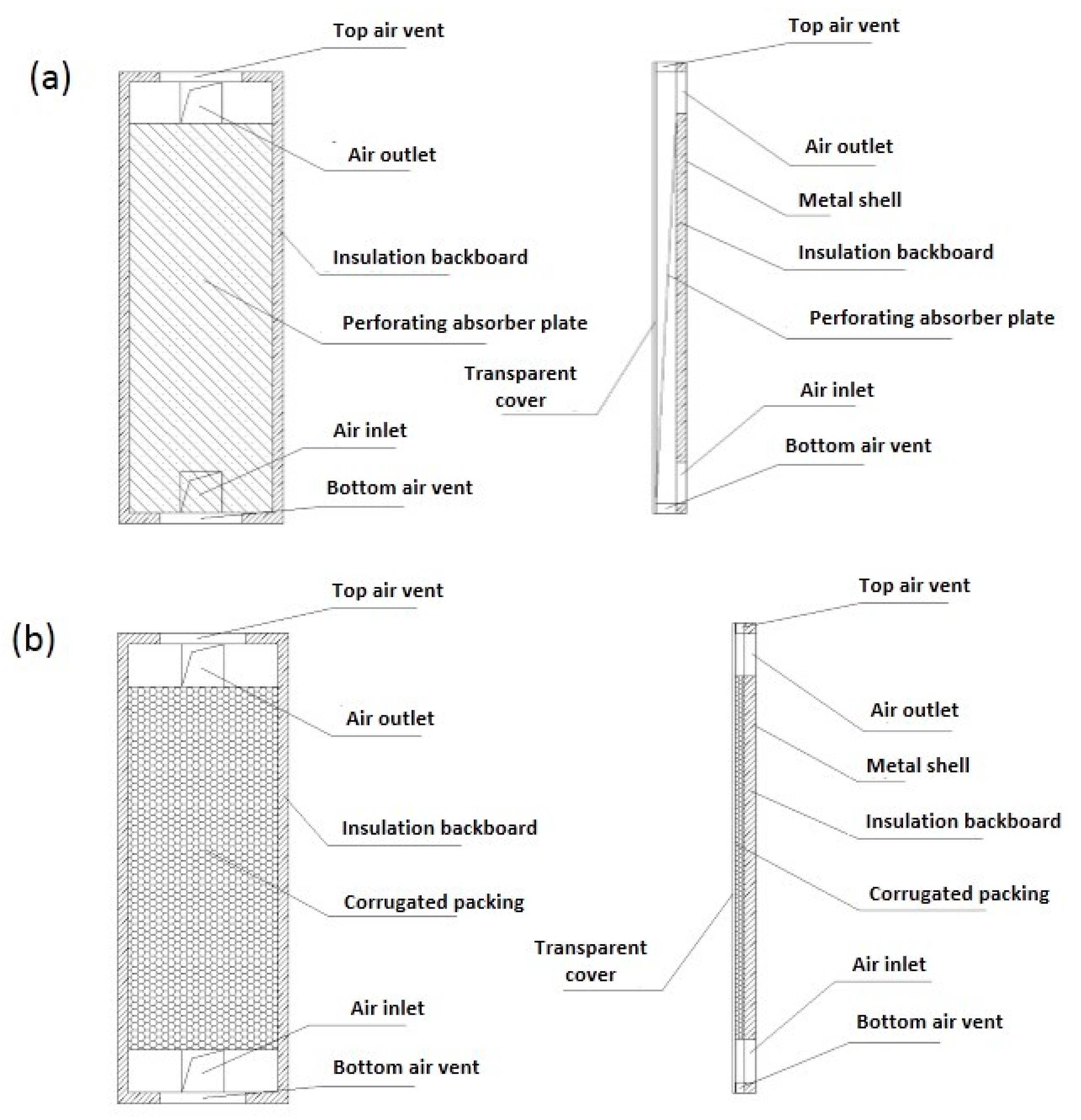
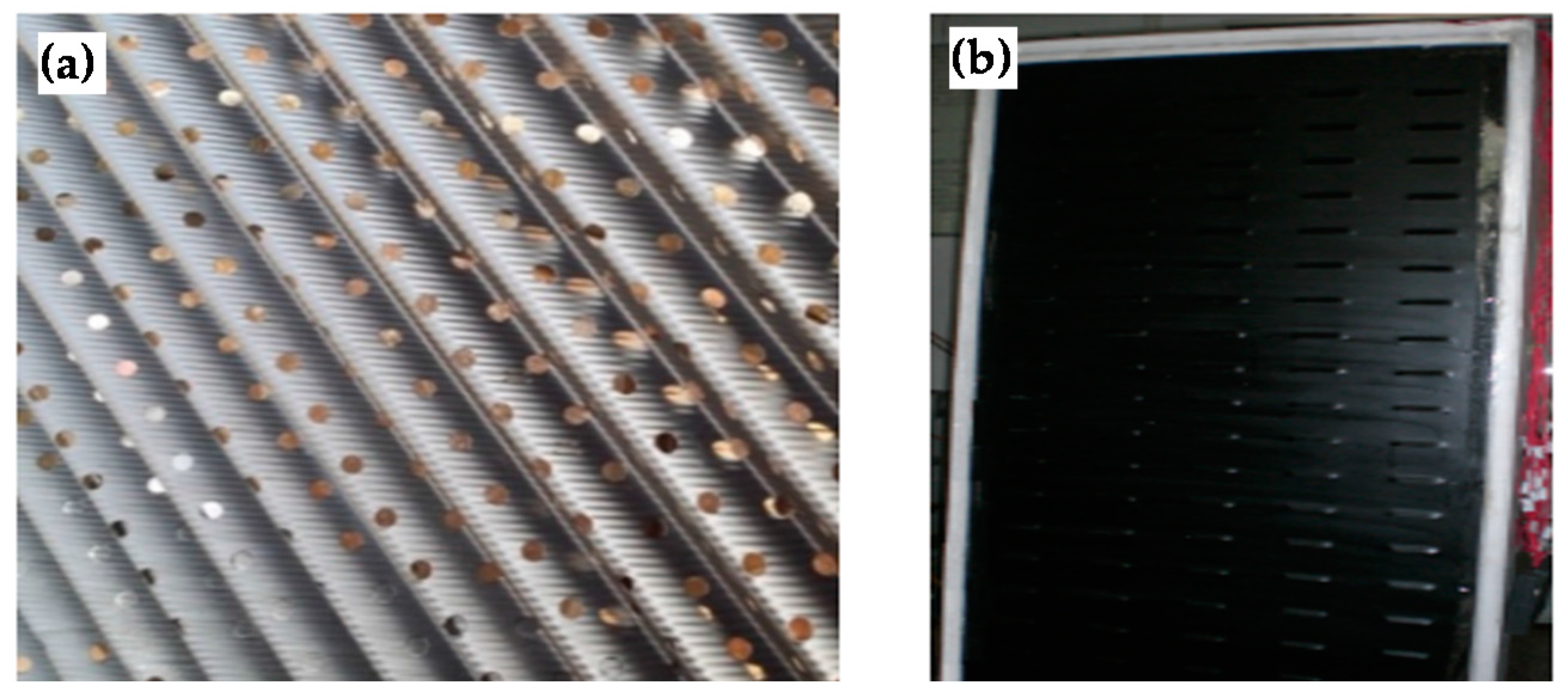
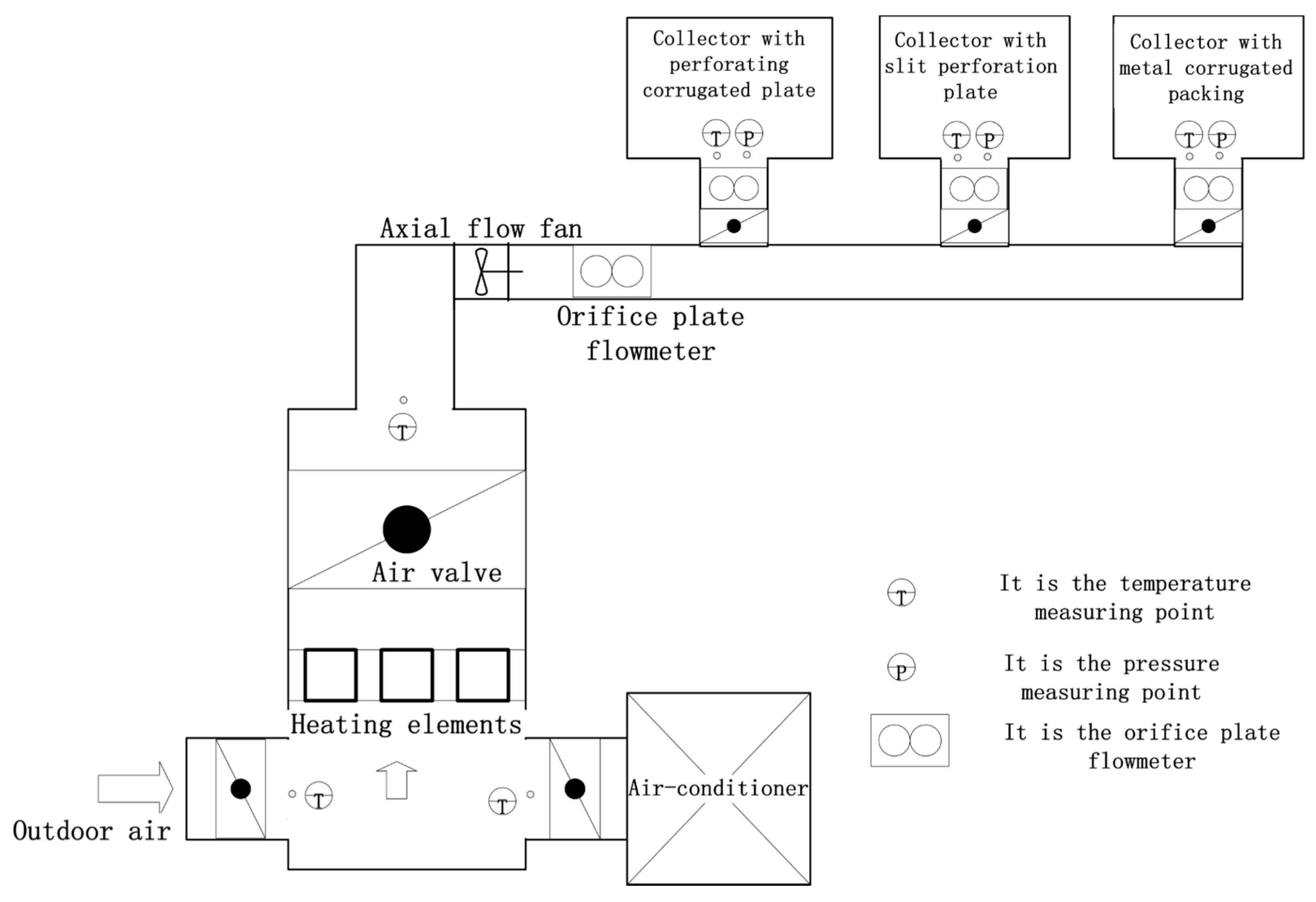
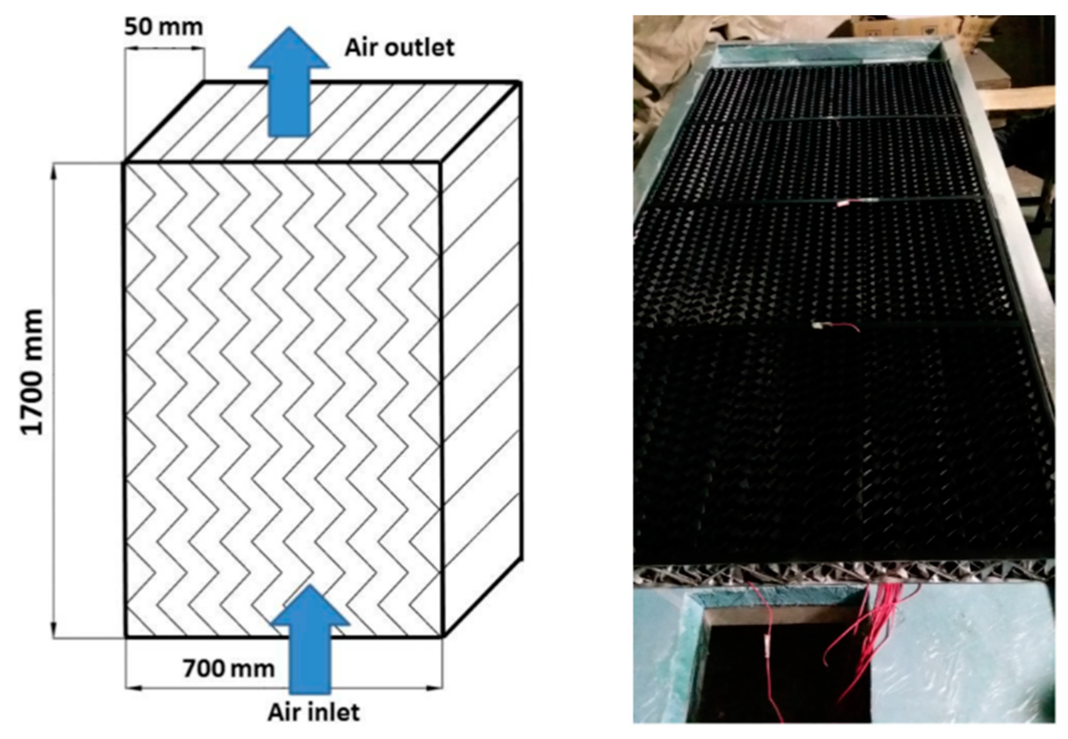
2. Experimental Setup

In the present study, experiments were conducted in the laboratory of Tianjin University. The thermal performance of three different solar air collectors was tested for a week in December 2015. The structure of the solar air collectors is shown in Figure 1.
The three solar air collectors have the same dimensions. The size of the solar collectors are about 2.2 m in length, 0.8 m in width, and 0.16 m in thickness. The aperture area of the solar collectors are about 2.1 m in length and 0.7 m in width. The air outlet and inlet with the dimensions of 200 mm × 200 mm are opened at the backside of the collector at a distance of 50 mm away from the top and bottom. Transparent polycarbonate covers with anti-UV (the absorptivity is 0.1 and the transmittance of solar radiation is 82%) are used above the collectors to reduce the thermal losses, which could lighten its weight and lower its cost. To support and protect the internal components, the collector frame is made of 1.2 mm galvanized steel. Extruded polystyrene boards with a thickness of 50 mm surround the frame to prevent the heat losses. The lengths of the air ducts is 700 mm, and there is a valve inside each inlet duct of the three collectors to adjust the air flow volume.
There are two kinds of perforated absorber plate, the slit perforate plate and the perforating corrugated plate. The size of the two absorber plates are about 1.9 m in length, 0.7 m in width, and the thickness is 0.15 mm with porosities of 10%. The perforations of the slit-perforated plate are 80 mm in length and 1 mm in width with 24 lines and 5 columns, while the perforation diameter is about 4 mm for the perforating corrugated plate. The specific surface area of the corrugated plate is about 250 m2/m3. The two absorber plates are shown in Figure 2. The corrugated packing with the specific surface area of 250 m2/m3 is also adopted to absorb the solar radiance. The size of the corrugated packing is about 1700 mm in length, 700 mm in width, and 50 mm in thickness. The corrugated packing is stacked with an angle of 90° while each of them have a 45° corrugation angle, as shown in Figure 3. To increase the absorption of solar radiation, the perforated absorber plate and the aluminum alloy corrugated packing are coated with dull black paint with an absorptivity of 0.96.
Experiments are conducted to test the thermal performance of the collectors. The experimental system is shown in Figure 4. A chamber with a PID (Proportion Integration Differentiation) temperature controller is designed to control the inlet air temperature of the collectors. To study the thermal performance of the solar air collectors in the cold and severe cold regions, an air-conditioner is introduced to lower the supply air temperature as the outdoor air temperature varies from 267 to 273 K during the tests. The supply temperature of the chamber can be as low as 261 K. Electrical heating elements are also installed to control the supply temperature. With the PID temperature controller, the inlet temperature of the solar air collectors can be changed from 261 to 283 K. K-type thermocouples are used to monitor the temperatures of inlet and outlet air of the solar air collectors, ambient air temperature, outlet air temperature of the air-conditioner, and the air in the chamber. The monitoring temperature data is recorded automatically by a Fluke Data Acquisition device (Fluke Corporation, Washington, D.C., USA). The thermocouples used in the experiments are verified in a high-precision constant temperature water bath to ensure measuring accuracy. The solar radiation intensity is measured by the radiometer TRT-2 (Heng Odd Instrument Corporation, Beijing, China) and it is placed parallel to the collector aperture. The air speeds for the indoor air, outdoor air, and outlet of the collectors are measured by a hot-wire anemometer TSI Q-Tray 7565 (TSI Corporation, Lebanon, TN, USA). At the inlet of each collector and the outlet of the chamber there are orifice plate flowmeters which are used to test the flow rates of the air duct and the solar collectors. The pressure drops of the solar collector are monitored by microelectronic pressure gauge ADM-860C (Shortridge Instruments Corporation, Scottsdale, AZ, USA). The accuracy of the instruments used in the experiment is specified in Table 1.
The accuracy of the measured data and experimental results is discussed according to Moffat [16]. An uncertainty analysis is conducted to validate the experimental results.
W p = [ ( p x 1 w 1 ) 2 + ( p x 2 w 2 ) 2 + ( p x 3 w 3 ) 2 + + ( p x n w n ) 2 ] 1 / 2
where p is a given function in terms of the independent variables; Wp is the uncertainty in the result; wn is the uncertainty in the independent variables.
The result, p, is a given function of the independent variables x1, x2xn. If the uncertainties in the independent variables are all given with the same odds, then uncertainty in the result having these odds can be calculated. The uncertainty for the temperature is established to be ±3.47%. The uncertainty for the air velocity is approximately ±4.56%. The uncertainty of the pressure drops is about ±4.32%. The thermal efficiency can be calculated by Equation (2), which is associated with the temperate, flow rate, and radiation intensity. The calculated uncertainty of the thermal efficiency is about ±5.13%, an acceptable uncertainty range in engineering application.
The operation strategy of the experimental system is displayed in this paper. The air- conditioner and the axial fallow fan is started at the beginning of the experiments to lower the temperature of the chamber. Then, the valves at the outlet of the air-conditioner and that at the end of the air duct open to circulate the air in the chamber. When the temperature of the air in the chamber comes to the lowest temperature (261 K) and remains stable, the valves of the solar air collectors open and switch on the data acquisition system. The openings of the valves at the bottom left and right of the chamber are mediated to control the inlet air proportion of the outdoor air and the air from the air-conditioner. As the input of outdoor air increases, the inlet air temperatures of the solar air collectors increase. The electrical heating elements will start to work while the required inlet air temperature is higher than the outdoor air temperature. The heating capacity can be controlled by a PID temperature controller. The inlet air flow rates of the solar air collectors are controlled by the valves at the air inlet.

3. Experimental Results and Discussion

Experiments were conducted in Tianjin in the clear days of December 2015. The outdoor air temperature was varied from 267 to 273 K during the tests. To compare the thermal efficiency of the solar air collectors in the cold regions, an air-conditioner was introduced to the experimental system to lower the inlet temperature of the collectors.

3.1. Evaluation Index

For solar air collectors, thermal efficiency is an important index to evaluate thermal performance. It is the ratio of the useful heat output to the total solar energy input on the collector surface.
η = Q I A = C p m ( T out T in ) I A
where η is the thermal efficiency of the solar air collectors; Cp is the specific heat capacity of air, J/(kg·K); m is the mass flow rate of air, kg/s; Tout is the outlet air temperature, K; Tin is the inlet air temperature, K; I is radiation intensity, W/m2; and A is the aperture area of the solar collectors, m2.

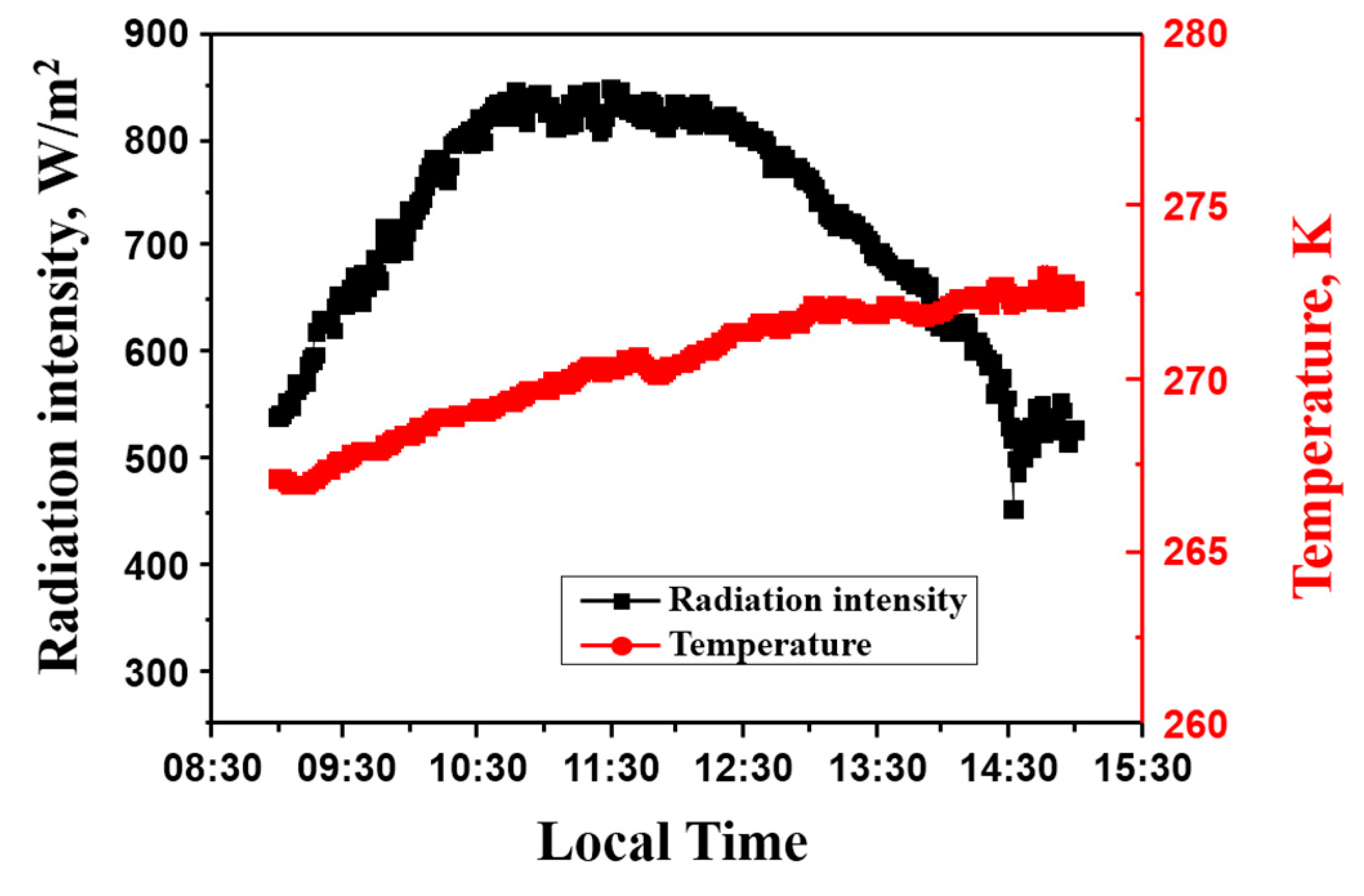
3.2. Variation of Outdoor Air Temperature and Radiation Intensity

The radiation intensity and outdoor air temperature in a typical day is shown in Figure 5. Experiments were conducted from 9 a.m. to 3 p.m. on the clear days. From Figure 5, it could be seen that the radiation intensity varied from 440 to 830 W/m2 and the outdoor air temperature changed from 267 to 273 K. The maximum value of radiation intensity was at noon time and the mean solar intensity in the particular day was about 721 W/m2. The outdoor air temperature was increased as time went on and the maximum value was 273 K at about 2 p.m. The average temperature in the testing day was about 270.5 K. The average value of wind measured during the tests was about 0.34 m/s.

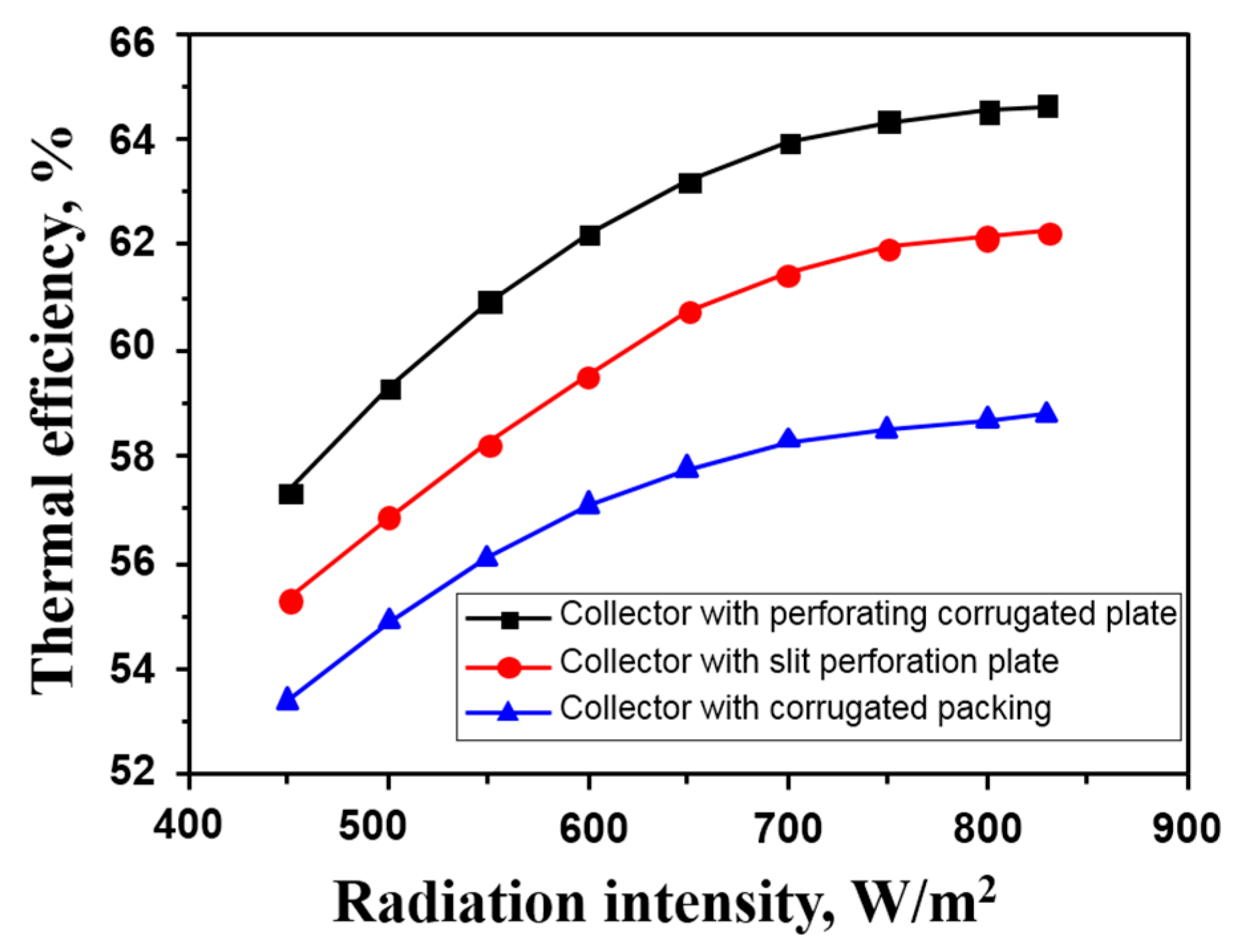
3.3. Effects of Radiation Intensity

Experiments were conducted to study the thermal efficiency of the three solar air collectors in various radiation intensities and the results were illustrated in Figure 6. The inlet temperature was fixed to be 270 K and the flow rate was 90 m3/h. From the figure, we could conclude that the thermal efficiency of the solar air collectors was increased as the increase of radiation intensity. It could be attributed to the increase of outlet air temperature and the temperature difference between the inlet and outlet air. The collector with perforating corrugated plate had a higher thermal efficiency than the other two collectors during the tests. This was because the effects of jet impingement of the air through the perforating corrugated plate which could enhance the convective heat transfer. Furthermore, compared with the collector with slit-perforated plate, the thermal efficiency of the collector with perforating corrugated plate was a bit higher for enlarging the heat transfer area.

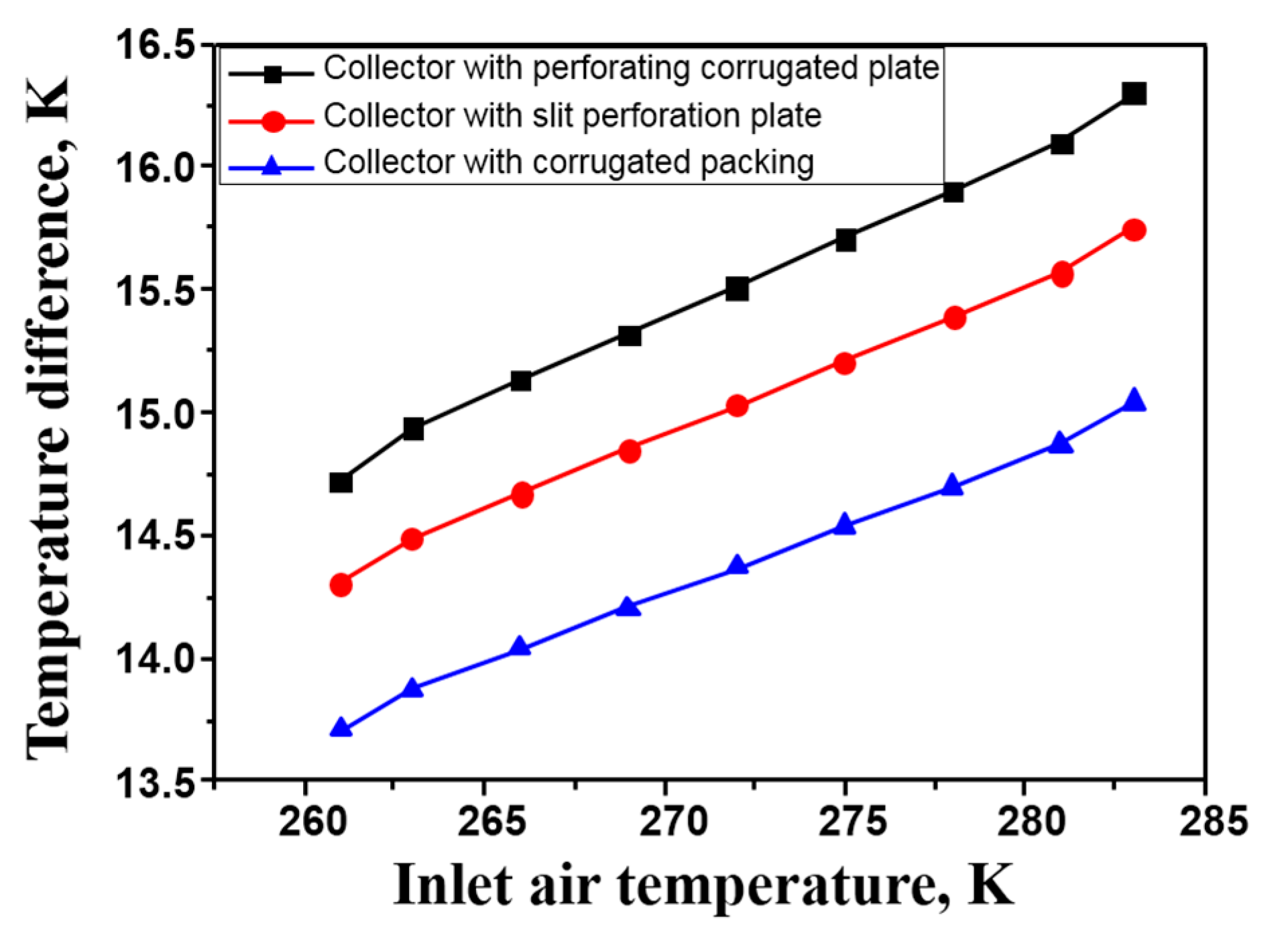
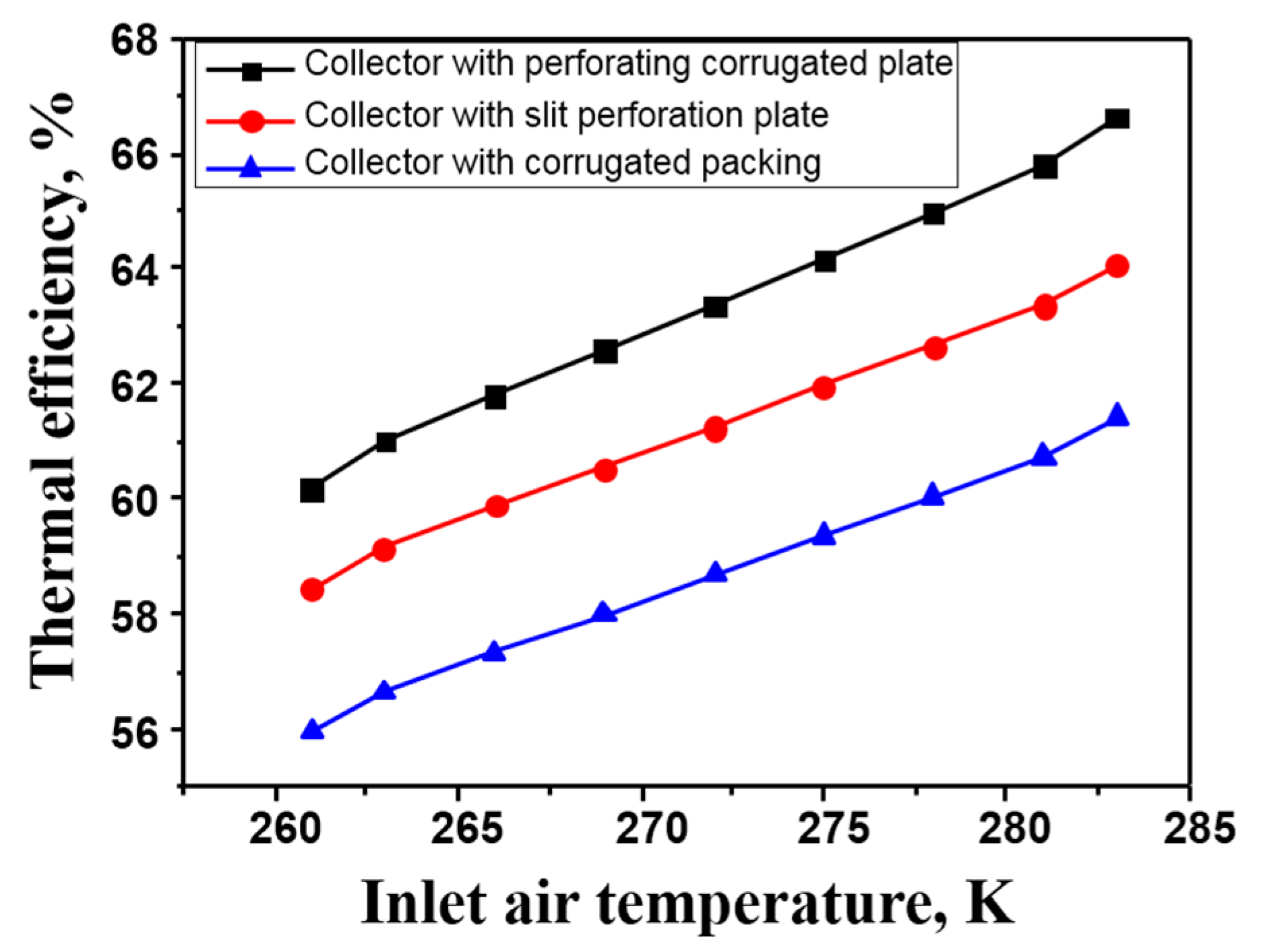
3.4. Effects of Inlet Temperature

To study the thermal performance of the three solar air collectors in cold and severe cold regions, experiments were conducted with inlet air temperature varying from 261 to 283 K (−12 to 10 °C). The ambient air temperature was varied from 267 to 273 K during the tests. With the application of transparent polycarbonate covers and the extruded polystyrene boards, the differences of heat losses could be ignored.
Experiments were conducted while the radiation intensity was about 650 W/m2 and the inlet air flow rate was 90 m3/h, the results were illustrated in Figure 7 and Figure 8. The experimental results indicated that the thermal efficiency of the three solar air collectors could be more than 55% in the severe cold regions. However, the outlet air temperature was about 275 K while the inlet temperature was 261 K, which could not satisfy the thermal comfort of the buildings in severe cold regions. While the inlet air temperature reached 265 K, the outlet air temperature of the collector with perforating corrugated plate could reach 291 K, which was the required minimum indoor air temperature for space heating. The results indicated that although the collectors have high thermal efficiency, it is also necessary to ensure that the outlet air temperature can satisfy the heating demands of buildings in the cold and severe cold regions. The outlet air temperature of the collectors should be higher than 291 K. Therefore, experiments were conducted to lower the inlet air flow rate and raise the outlet air temperature to satisfy heating demands.

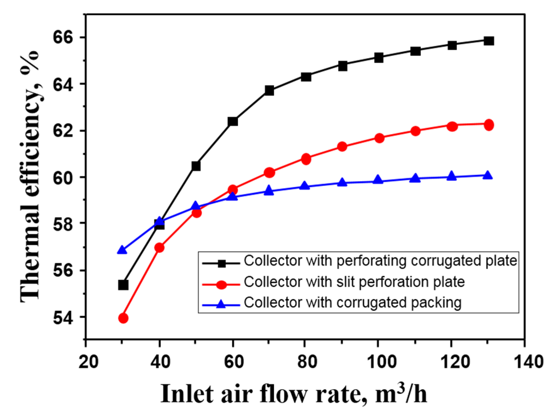
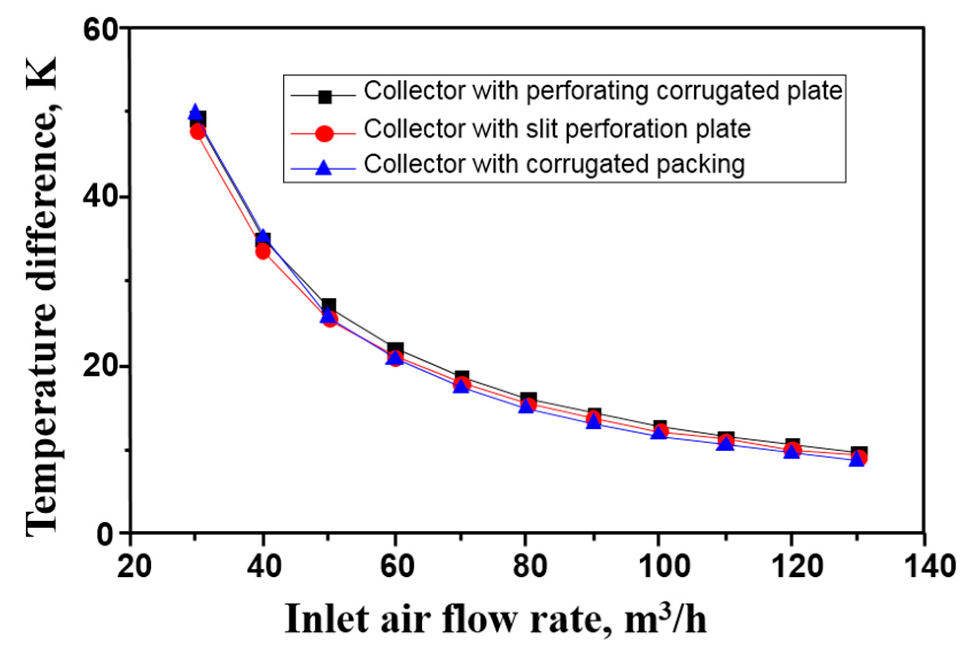
3.5. Effects of Flow Rate

To raise the outlet air temperature, the inlet air flow rate was varied from 20 to 130 m3/h during the tests. The experimental results were listed in Figure 9 and Figure 10. Experiments were conducted while the inlet air temperature was 261 K and the radiation intensity was about 650 W/m2. The results indicated that the thermal efficiency of the collector with corrugated packing was higher while the inlet air flow rate was lower than 40 m3/h. It was caused by the larger heat transfer area and the full heat exchange between the air and the corrugated packing. As inlet air flow rate increased, the thermal efficiency of the collector with perforating corrugated plate became much higher than the other two collectors. This can be attributed to the effects of jet impingement of the air through the perforating corrugated plate and the enhancement of the convective heat transfer.
As illustrated in Figure 10, the temperature difference could be as high as 50 K while the inlet air flow rate was reduced to 30 m3/h. The outlet air temperature could be higher than 291 K while the inlet air flow rate was lower than 45 m3/h, which was high enough to satisfy the thermal comfort of the buildings in severe cold regions. Therefore, the application of solar air collectors in cold and severe cold regions should be on the condition of low flow rate to satisfy the thermal comfort of the buildings.

3.6. Pressure Drops

The pressure drops of solar air collectors could be categorized into three types: air flowing resistance, local resistance, and buoyancy lift. The pressure drops of the collectors could be formulated as
Δ P = Δ P m + Δ P f Δ P byc
where Δ P m is the local resistance, Pa; Δ P f is the flowing resistance, Pa; and Δ P byc is the buoyancy lift, Pa.
The local resistance of the solar air collector could be calculated by the empirical formula of Kutscher [17]
Δ P m = ε m ρ u hole 2 2
ε m = 6.82 ( 1 / P 1 ) 2 Re hole 0.24
The buoyancy lift could be predicted by Dymond [6]:
Δ P byc = Δ ρ g H
The air flow resistance was experimentally studied. The correlations between the friction factor and Reynolds number were illustrated in Figure 11.
The correlation between the friction factor and Reynolds number for the collector with perforating corrugated plate was:
f = 57.75 Re 0.729 , R 2 = 0.912
The correlation between the friction factor and Reynolds number for the collector with slit-perforated plate was:
f = 134.31 Re 0.894 , R 2 = 0.901
The correlation between the friction factor and Reynolds number for the collector with corrugated packing was:
f = 32.88 Re 0.614 , R 2 = 0.919
The results indicated that the pressure drops of the collector with slit-perforated plate was the least and the collector with corrugated packing was the most. Although the pressure drops of the collector with perforating corrugated plate was a little larger than the collector with slit-perforated plate, the thermal efficiency and outlet air temperature was higher. Therefore, the collector with perforating corrugated plate was more suitable to be used in the cold and severe cold regions.

3.7. Economic Analysis

An economic analysis is performed to study the application of the three solar air collectors in the cold rural regions. Take a house with the built-up area of 40 m2 and the height of 3.2 m as an example. The heating load of the house is about 4.6 kW. The electricity price is about 0.85 RMB/kWh. The life cycle of the metal corrugated packing solar air collector is 20 years. The life cycle cost can be calculated by the Equations (10) and (11).
C = P + A ( 1 + n ) n 1 i ( 1 + n ) n
A = 0.85 Δ P Q ε
where C is the life cycle cost, RMB; P is the initial cost, RMB; A is the annual operating cost, RMB; n is the life cycle; i is the discount rate; Δ P is the pressure drops, Pa; and Q is the volume flow of air, m3/h.
The economic characteristics of the metal corrugated packing solar air collector are listed in Table 2. The results indicate that the life cycle cost of the solar air collector with perforating corrugated plate is the lowest. Although the power consumption of the collector with perforating corrugated plate is higher than that with slit-perforated plate while the air flow rate is the same, the operation cost is lower for its better thermal performance. The life cycle cost of the collector with corrugated packing is the highest for its high operating cost. All three collectors can satisfy the thermal comfort requirements of the buildings in severe cold regions and reduce the emission of pollutants caused by heating.

4. Conclusions

In this study, the thermal performance of a solar air collectors with perforating corrugated plate, slit-perforated plate, and corrugated packing in cold and severe cold regions were experimentally studied. The study is very helpful for the popularization and application of solar air collectors in the cold and severe cold regions. The main conclusions of the present investigation can be summarized as:
(1)
As the effects of jet impingement of the air through the perforating corrugated plate and the enlarging of heat transfer area, the thermal performance of the solar air collector with perforating corrugated plate is higher than the other collectors.
(2)
The flow rate of inlet air has significant effects on the thermal comfort of buildings in cold and severe cold regions. The experimental results indicate that the inlet air flow rate should be lower than 45 m3/h to satisfy the thermal comfort of buildings in severe cold regions.
(3)
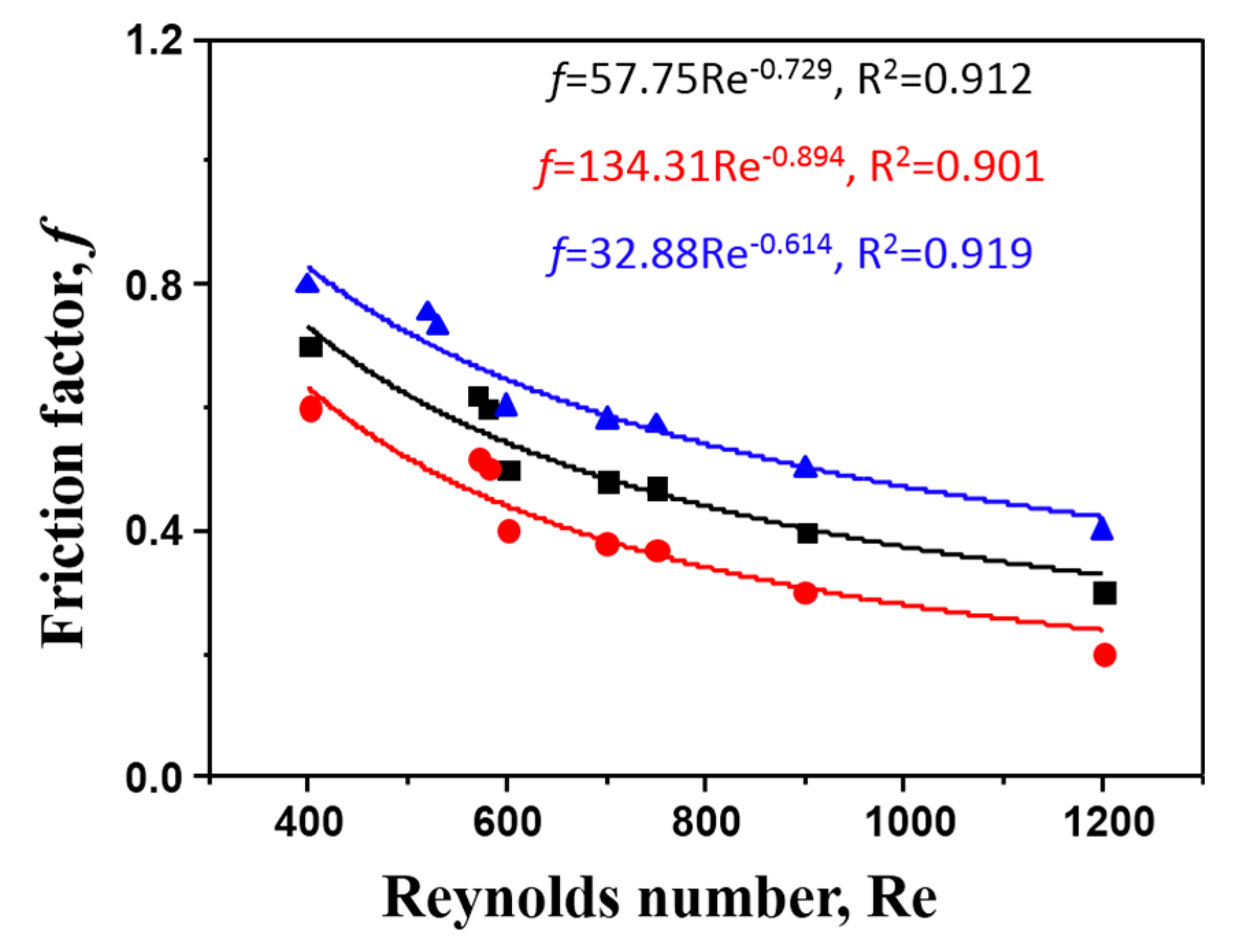
The correlations between the friction factor and Reynolds number of the three collectors are fitted with the experimental results. The dynamics analysis results indicate that the pressure drop of the collector with slit-perforated plate was the least and the pressure drop of the collector with corrugated packing was the most.
(4)
Although the pressure drop and power consumption of the collector with perforating corrugated plate was a little larger than the collector with slit-perforated plate while the air flow rate is the same, the operation cost is lower for its better thermal performance. Therefore, the collector with perforating corrugated plate was more suitable for use in the cold and severe cold regions.

Acknowledgments

This study is supported by the Opening Funds of State Key Laboratory of Building Safety and Built Environment (No. BSBE2016-09), Science and Technology Project of Urban-Rural Construction Commission of Tianjin Municipality (No. 2016-18) and the China Postdoctoral Science Foundation (No. 2016M600189).

Author Contributions

Wandong Zheng, Huan Zhang, Shijun You and Yindan Fu conducted the experiments together; Wandong Zheng and Yindan Fu wrote this paper; Huan Zhang and Shijun You designed the experimental system. All the authors contributed equally to this work.

Conflicts of Interest

The authors declare no conflict of interest.

References

  1. Vaziri, R.; Ilkan, M.; Egelioglu, F. Experimental performance of perforated glazed solar air heaters and unglazed transpired solar air heater. Sol. Energy 2015, 119, 251–260. [Google Scholar] [CrossRef]
  2. Altfeld, K.; Leiner, W.; Fiebig, M. Second law optimization of flat-plate solar air heaters. Sol. Energy 1988, 41, 127–132. [Google Scholar] [CrossRef]
  3. Ekechukwu, O.V.; Norton, B. Review of solar-energy drying systems III: Low temperature air-heating solar collectors for crop drying applications. Energy Convers. Manag. 1990, 40, 657–667. [Google Scholar] [CrossRef]
  4. Li, B.J.; You, S.J.; Ye, T.Z.; Zhang, H.; Li, X.L.; Li, C. Mathematical modeling and experimental verification of vacuum glazed transpired solar collector with slit-like perforations. Renew. Energy 2014, 69, 43–49. [Google Scholar] [CrossRef]
  5. Li, X.L.; Li, C.; Li, B.J. Net heat gain assessment on a glazed transpired solar air collector with slit-like perforations. Appl. Therm. Eng. 2016, 99, 1–10. [Google Scholar] [CrossRef]
  6. Kutscher, C.; Dymond, C. Development of a flow distribution and design model for transpired solar collectors. Sol. Energy 1997, 60, 291–300. [Google Scholar]
  7. Decker, G.W.E.V.; Hollands, K.G.T.; Brunger, A.P. Heat-exchange relations for unglazed transpired solar collectors with circular holes on a square or triangular pitch. Sol. Energy 2001, 71, 33–45. [Google Scholar] [CrossRef]
  8. Kumar, A.; Saini, R.P.; Saini, J.S. Development of correlations for Nusselt number and friction factor for solar air heater with roughened duct having multi v-shaped with gap rib as artificial roughness. Renew. Energy 2013, 58, 151–163. [Google Scholar] [CrossRef]
  9. Nowzari, R.; Aldabbagh, L.; Egelioglu, F. Single and double pass solar air heaters with partially perforated cover and packed mesh. Energy 2014, 73, 694–702. [Google Scholar] [CrossRef]
  10. Saxena, A.; Varun; El-Sebaii, A.A. A thermodynamic review of solar air heaters. Renew. Sustain. Energy Rev. 2015, 43, 863–890. [Google Scholar] [CrossRef]
  11. Gao, L.X.; Bai, H.; Mao, S.F. Potential application of glazed transpired collectors to space heating in cold climates. Energy Convers. Manag. 2014, 77, 690–699. [Google Scholar] [CrossRef]
  12. Zheng, W.; Li, B.; Zhang, H.; You, S.; Li, Y.; Ye, T. Thermal characteristics of a glazed transpired solar collector with perforating corrugated plate in cold regions. Energy 2016, 109, 781–790. [Google Scholar] [CrossRef]
  13. Bhushan, B.; Singh, R. Thermal and thermohydraulic performance of roughened solar air heater having protruded absorber plate. Sol. Energy 2012, 86, 3388–3396. [Google Scholar] [CrossRef]
  14. Chauhan, R.; Thakur, N.S. Investigation of the thermohydraulic performance of impinging jet solar air heater. Energy 2014, 68, 255–261. [Google Scholar] [CrossRef]
  15. El-Khawajah, M.; Aldabbagh, L.; Egelioglu, F. The effect of using transverse fins on a double pass flow solar air heater using wire mesh as an absorber. Sol. Energy 2011, 85, 1479–1487. [Google Scholar] [CrossRef]
  16. Moffat, R.J. Describing the experimental uncertainties in experimental results. Exp. Therm. Fluid Sci. 1988, 1, 3–17. [Google Scholar] [CrossRef]
  17. Kutcher, C.F. Heat exchange effectiveness and pressure drop for air flow through perforated plates with and without crosswind. J. Heat Transf. Trans. ASME 1994, 116, 391–399. [Google Scholar] [CrossRef]
Figure 1. Schematic diagram of glazed transpired solar air collector with (a) slit-perforated plate and perforating corrugated plate and (b) metal corrugated packing.
Energies 10 00302 g001
Figure 2. Structure of the (a) perforating corrugated plate and (b) slit-perforated plate.
Energies 10 00302 g002
Figure 3. Structure of the corrugated packing.
Energies 10 00302 g003
Figure 4. Schematic diagram of the experimental system.
Energies 10 00302 g004
Figure 5. Variation of radiation intensity and outdoor air temperature during the tests.
Energies 10 00302 g005
Figure 6. Comparison of collectors at different radiation intensities.
Energies 10 00302 g006
Figure 7. Effects of inlet air temperature on the thermal efficiency.
Energies 10 00302 g007
Figure 8. Effects of inlet air temperature on the temperature difference.
Energies 10 00302 g008
Figure 9. Effects of inlet air flow rate on the thermal efficiency.
Energies 10 00302 g009
Figure 10. Effects of inlet air flow rate on the temperature difference.
Energies 10 00302 g010
Figure 11. Friction factor plotted against Reynolds number of the three collectors.
Energies 10 00302 g011
Table 1. Accuracy of the instruments used in the experiment.
InstrumentsAccuracyInstrumentsAccuracy
K-type thermocouples±0.75%t °CMicroelectronic pressure gauge±(2% + 0.25)
Radiometer±2%
Flowmeter±3%Hot-wire anemometer±0.02 m/s
Table 2. Economic analysis of the three solar air collectors.
Solar Air CollectorInitial CostOperating CostLife Cycle Cost
Perforating corrugated plate3500 RMB7500 RMB11,000 RMB
Slit-perforated plate3000 RMB9000 RMB12,000 RMB
Corrugated packing3100 RMB10,300 RMB13,400 RMB

