1. Introduction
Cableless elevator systems based on linear machines are very attractive, since they can eliminate the drawbacks of conventional traction-geared cable elevators, such as the vertical oscillation and height limit caused by the strength and weight of cable [
1], especially in case of the skyscrapers of 200–400 m height. Moreover, multicar elevators in one hoistway can be achieved more easily when the elevator vehicles are driven by independent linear machines [
2], so a large proportion of the building space can be reclaimed. Hence, several kinds of linear machines have been investigated for cableless elevators. In [
3], a linear permanent magnet (PM) synchronous machine (LPMSM) is adopted for cableless elevators because of its high efficiency and high power density, in which the armature windings are laid along the hoistway and can be controlled section by section according to the elevator vehicle position. PMs are installed on the elevator vehicle. However, the cost of LPMSM is very high because of the long laid armature windings and the expensive power electronic equipment used to divide the armature windings into sections. Due to the simplicity and robustness of the secondary side, the linear switched reluctance machine (LSRM) is regarded as the preferred machine for cableless elevators [
4]. However, the thrust force ripple of LSRMs is relatively higher due to the complex and nonlinear magnetic circuit and the control difficulty of LSRM is consequently increased [
5].
In recent years, stator PM machines, namely the double salient PM (DSPM) machine, flux reverse PM (FRPM) machine and flux-switching PM (FSPM) machine have been widely investigated because of their advantages such as the simple and robust structure of the rotor [
6,
7]. Both the PMs and armature windings of stator PM machines are housed in the stator, and the rotor is composed of a simple and cheap iron core with salient teeth, so the linear counterpart of the stator PM machine, namely the linear primary PM machine, is very suitable for long stroke applications, such as cableless elevators and urban rail transit systems, in which the primary and the secondary can be designed as the short side and long side, respectively, to integrate the high efficiency and power density performances of LPMSMs and the low cost merit of LSRMs.
Compared with the DSPM machine and the FRPM machine, the FSPM machine possesses the merits of higher power density and torque density [
8], sinusoidal no-load EMF [
9] and fault-tolerance capability [
10,
11,
12,
13,
14], so FSPMs are attracting more and more attention and numerous novel rotary FSPM machines structures of have been proposed [
15,
16], such as the five-phase modular FSPM machine [
17] and the hybrid excitation FS machine [
18]. Meanwhile lots of linear versions of FSPM (LFSPM) machines also have been presented for linear industry applications [
19]. In [
20], E-core and C-core LFSPM machines were optimized and compared. Due to the improvement of the armature winding slot area compared with traditional U-core LFSPM machines, the C-core LFSPM machines can achieve a higher thrust force density and power density, in spite of the lesser usage of the PMs.
However, the performances of LFSPM machines, including U-core, E-core and C-core LFSPM machines are usually severely deteriorated due to the asymmetrical characteristics of the magnetic field as a result of the end effect, although two additional teeth can be added on the each end of the primary side. In order to obtain the symmetrical 3-phase flux linkage and no-load EMF, a complementary and modular E-core LFSPM machine is proposed for urban rail transit and the corresponding mathematical model is established [
21].
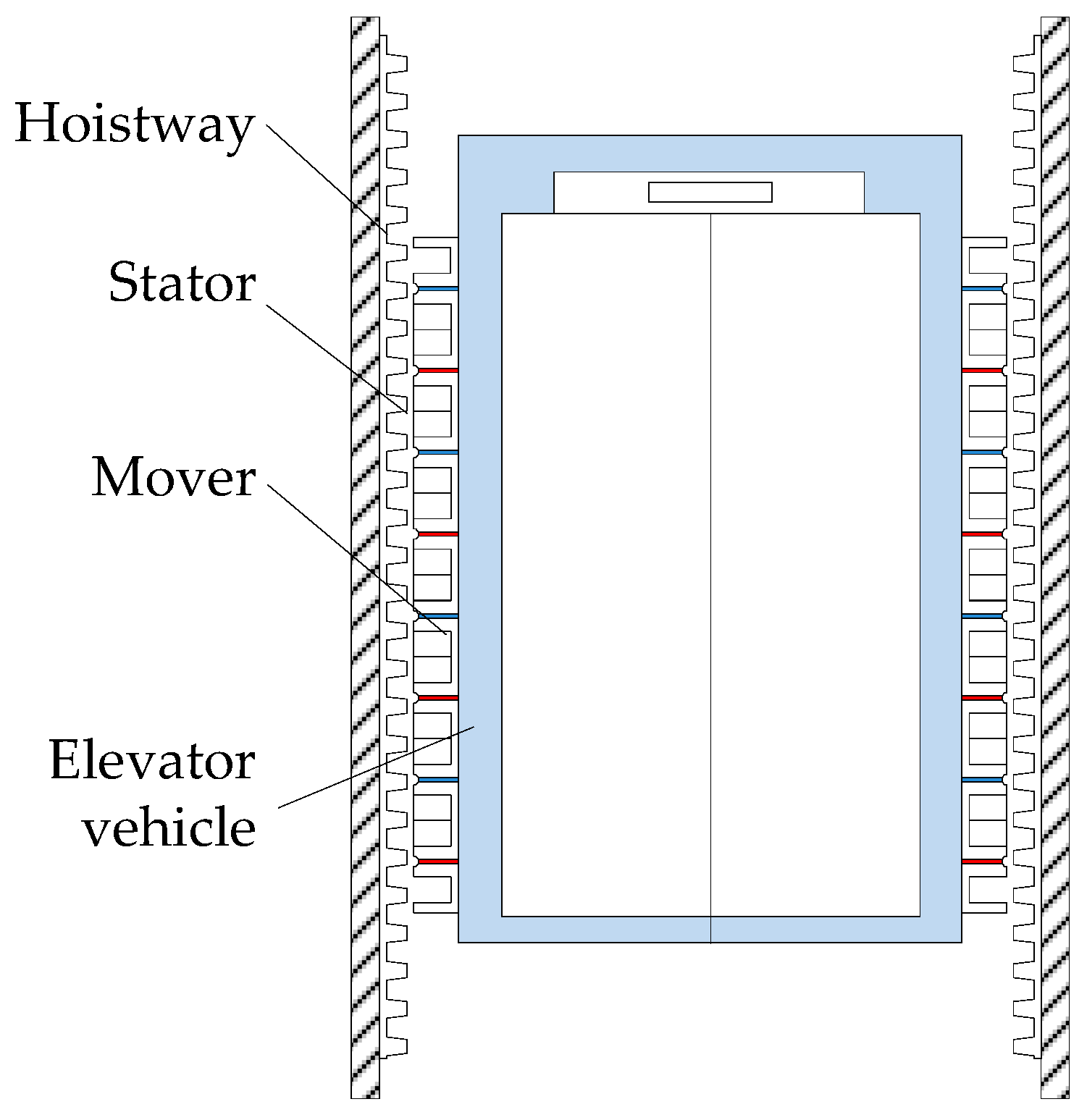
In this paper, a C-core LFSPM machine with two new multiple additional teeth is proposed for cableeless elevator direct drive systems. As shown in
Figure 1, two LFSPM machines are located in the two gaps, respectively, between the hoistway and the elevator vehicle to achieve a balanced lifting force. The primary side is installed on the outside of the elevator car and the secondary side is laid along the hoistway. In
Section 2, the machine configuration will be described and the operation principle will be introduced briefly. Then, the key parameters of the proposed machine will be optimized to achieve balanced electromagnetic performances and low detent force in
Section 3. In
Section 4, the characteristics of the C-core LFSPM machine will be analyzed by the 2-D finite element method (FEM). Finally, conclusions will be drawn in
Section 5.
2. Machine Configuration and Operation Principle
The performance and characteristics of LFSPM machines have been widely investigated.
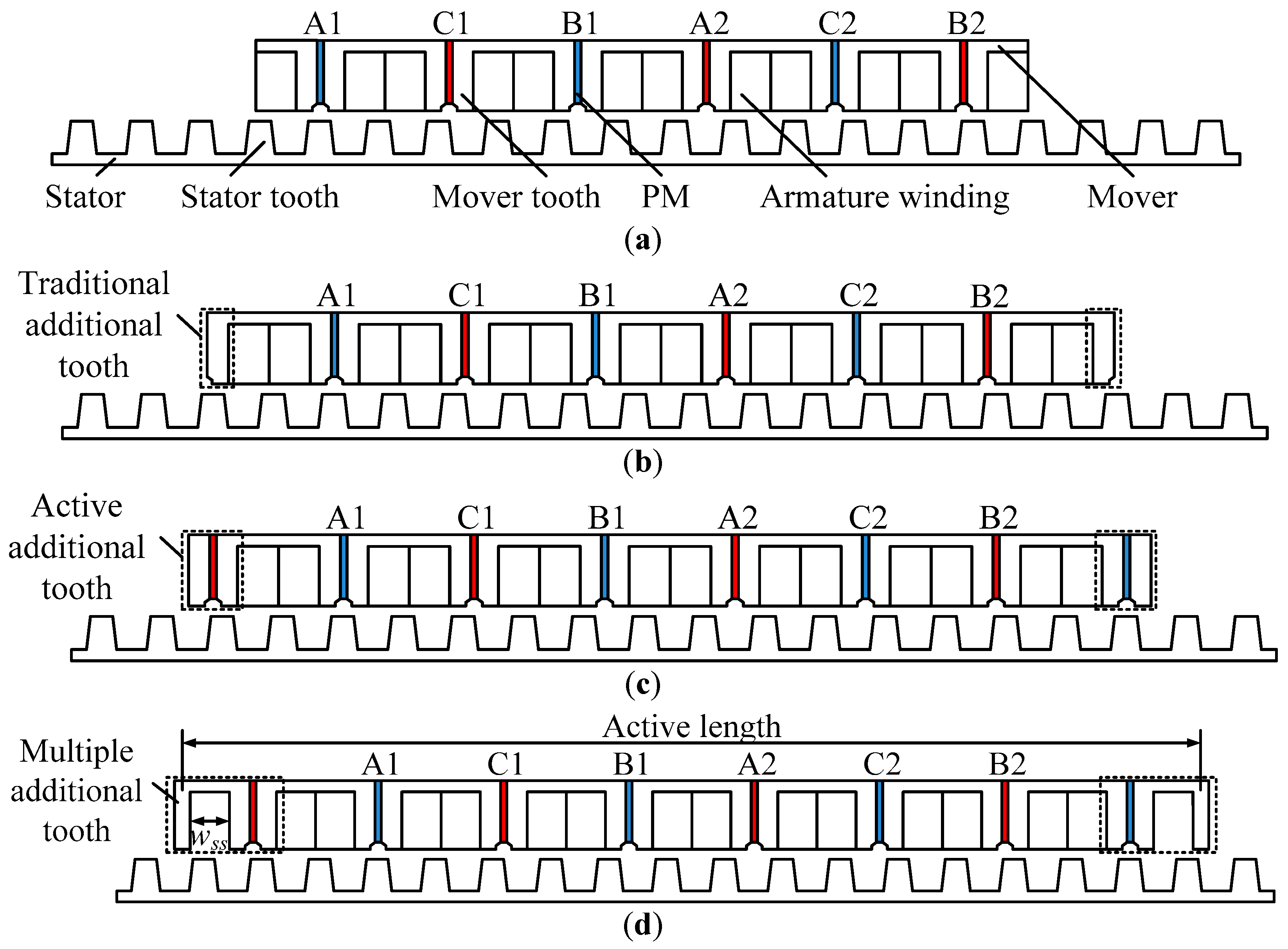
Figure 2a shows an original C-core LFSPM machine, named “Machine I” in this paper, which can be obtained by splitting a rotary 6/13-pole C-core FSPM machine along the radial direction and unrolling it. It should be notice that the 6/13 mover and stator pole combination is selected in this paper because it can achieve the maximum no-load EMF and thrust force [
20].
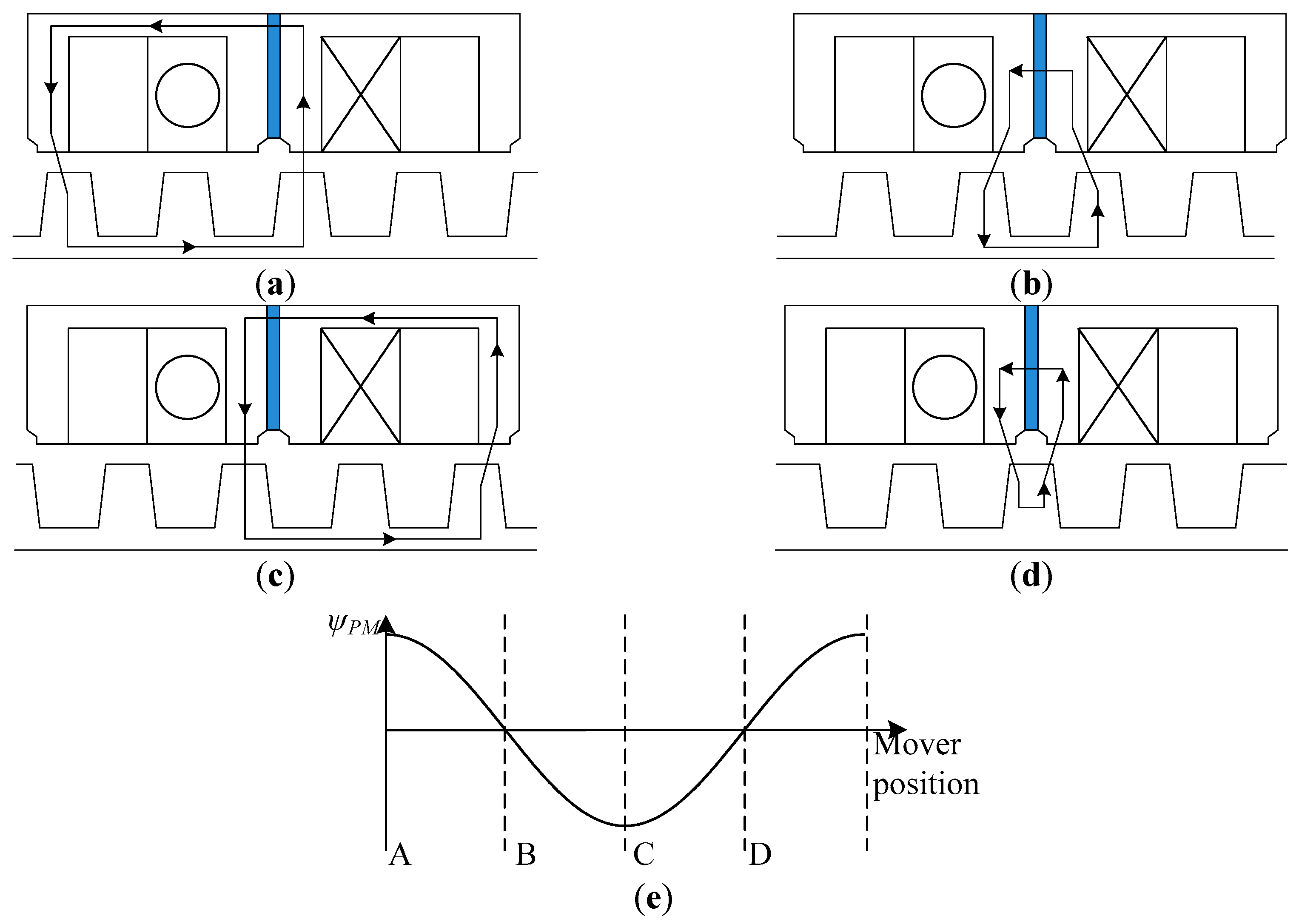
Figure 3 shows the operation principle of the 6/13-pole C-core LFSPM machine. Assuming the PM magnetizes towards the left-hand side, at the relative position of the stator tooth and the mover tooth as shown in
Figure 3a, the PM flux linkage of the coil nearly reaches the positive maximum. When the mover moves a quarter of the tooth pitch towards the left-hand side, as shown in
Figure 3b, the mover module is symmetrical about the central axis of the stator slot. At this moment, the PM flux linkage of the coil equals zero. When the mover moves 1/4 tooth pitch again, as shown in
Figure 3c, the PM flux linkage nearly reaches the negative maximum value. In
Figure 3d, the mover module is symmetrical about the central axis of the stator tooth. Thus the PM flux linkage of the coil equals zero again. Assuming an ideally sinusoidal PM flux linkage,
Figure 3e shows the PM flux linkage waveform when the mover travels one stator tooth pitch, in which positions A, B, C and D correspond to the positions in
Figure 3a–d, respectively.
In order to reduce the detent force, two passive additional teeth are adopted [
22] in a U-core LFSPM machine and the width of the side-slot has been optimized for the minimum detent force. Thus, the traditional passive additional teeth also can be employed in the C-core LFSPM machine, as shown in
Figure 2b, which is named as “Machine II” in this paper, to reduce the detent force. However, the other electromagnetic performances, such as the flux linkage and the inductance, are unbalanced due to the end effect of the linear machine not only in the Machine I but also in the Machine II.
In this paper, 2-D FEM models of the four machines shown in
Figure 2 have been built. Thus the machine characteristics can be obtained.
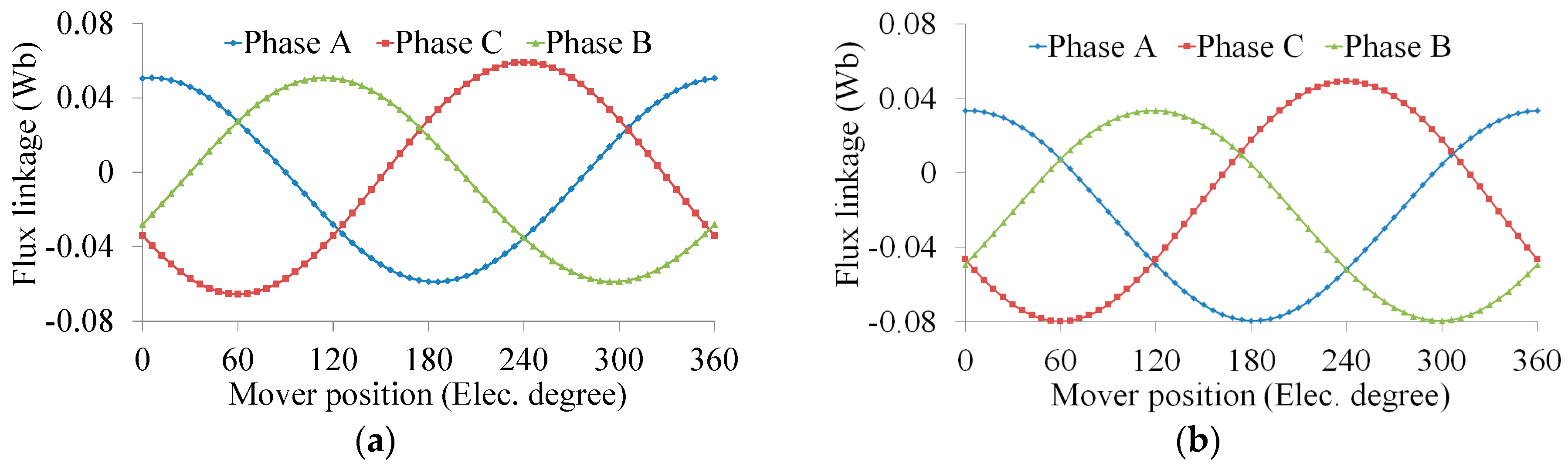
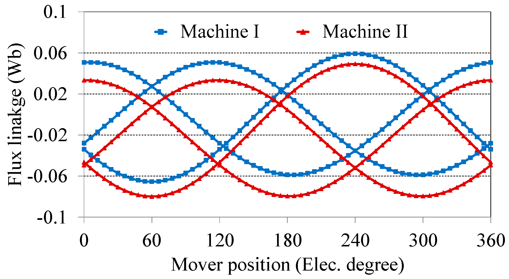
Figure 4 shows the 3-phase PM flux linkage waveforms of Machine I and Machine II. It can be seen that the flux linkage waveforms of Machine I are asymmetrical in the positive and negative half-cycle. Furthermore, the flux linkage waveforms of Machine II are more deteriorated compared with those of Machine I due to the magnetic circuit of the traditional additional teeth.
In order to balance the magnet circuit, two active additional teeth [
23] are added at each end of the primary side of Machine I, as shown in
Figure 2c, which is named as Machine III in this paper. It can be noticed that the active additional tooth is composed of two primary tooth iron cores and a PM block.
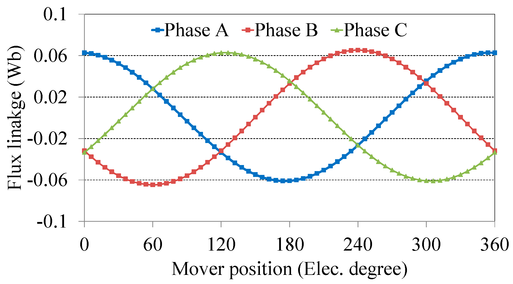
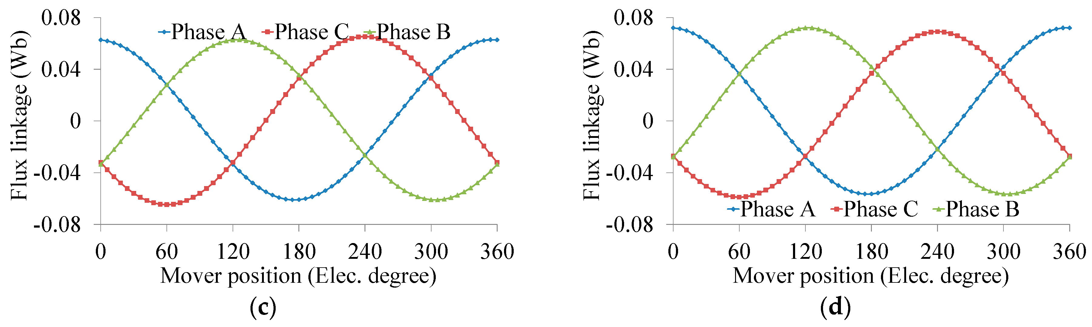
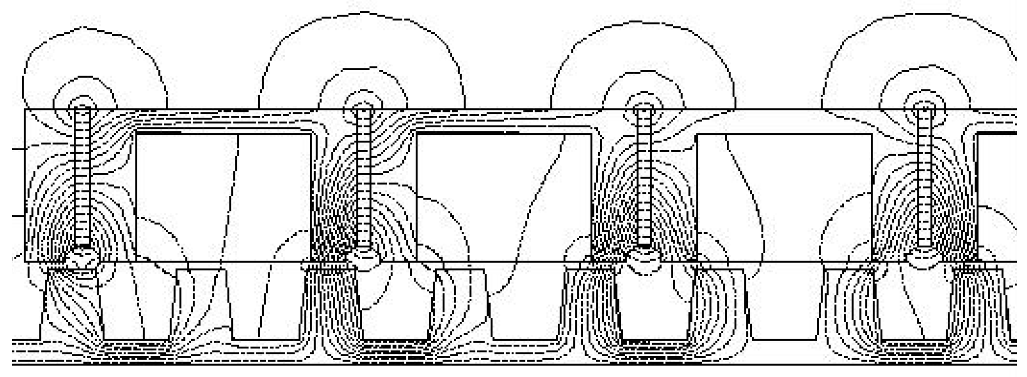
Figure 5 shows the no-load magnetic field distribution of Machine III. It can be seen that the flux contributed by the active additional tooth runs through the mover teeth, thus balancing the magnetic field asymmetry caused by the end effect of the linear machine. The 3-phase flux linkage waveforms of Machine III are expected to be more balanced than the other two counterparts. As shown in
Figure 6, the 3-phase flux linkage waveforms are nearly symmetrical in the positive and negative half-cycle.
The merit of the traditional passive additional teeth in Machine II is that the detent force can be optimized through adjusting the width of the side-slot. However, the side slot width cannot be changed arbitrarily in Machine III, which will deteriorate the phase and the amplitude of the flux linkage and no-load EMF, especially of phase A and phase B which are arranged to be close to the additional teeth, so a new multiple additional tooth, which is composed of an active additional tooth and a traditional passive tooth, is employed in the C-core LFSPM machine. As shown in
Figure 2d, in the proposed C-core LFSPM, which is named as Machine IV, both the PMs and armature windings are located in the primary side. The primary salient tooth wound with a concentrated winding consists of C-shaped laminated segments between which the PMs are sandwiched and the magnetization directions of these PMs are adjacent alternant in horizontal direction. And the secondary side is composed of a simple iron core with salient teeth so that it is very suitable to be used in long stroke applications, such as cableless elevators. Due to the use of two multiple additional teeth, the magnet circuit can be balanced and the detent force can be optimized through adjusting the width of the side slot,
wss.
3. Key Parameter Optimization
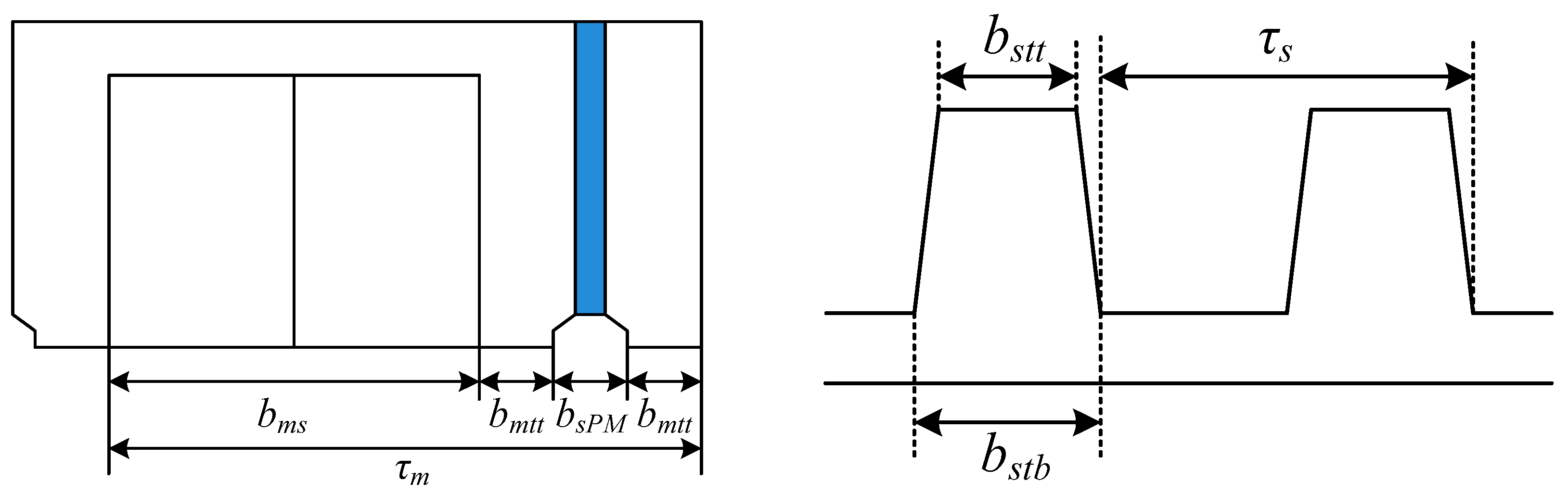
The proposed LFSPM machine with multiple additional teeth is operated based on the flux switching principle, which is same as the conventional FSPM machine. In this section, several key parameters will be optimized using the FEM in order to obtain the expected performances, such as the symmetry and sinusoidal 3-phase flux linkage and no-load EMF waveforms, the minimum detent force and the maximum average thrust force. It should be noted that the mover tooth tip width
bmtt and the slot under the PM
bsPM are designed to be equal to the one-eighth of the mover pitch
τm in the optimization process, as shown in
Figure 7, which is similar with the traditional FSPM machine [
9], thus the mover slot width
bms equals 5/8 times
τm, namely
bmtt =
bsPM = 1/8
τm = 1/5
bms.
Moreover, the individual parameter optimization method [
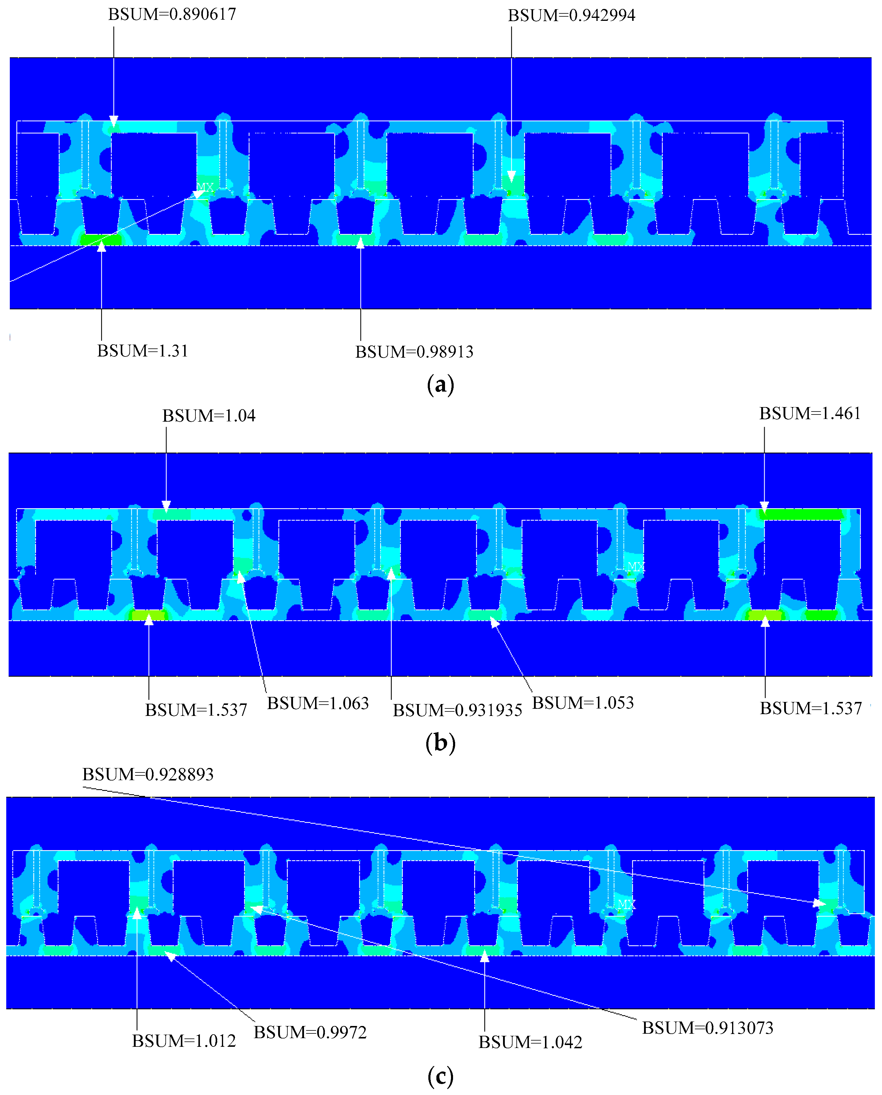
20] is adopted in the key parameter optimization. On the other hand, the magnetic flux density is considered to ensure the iron core to be unsaturation.
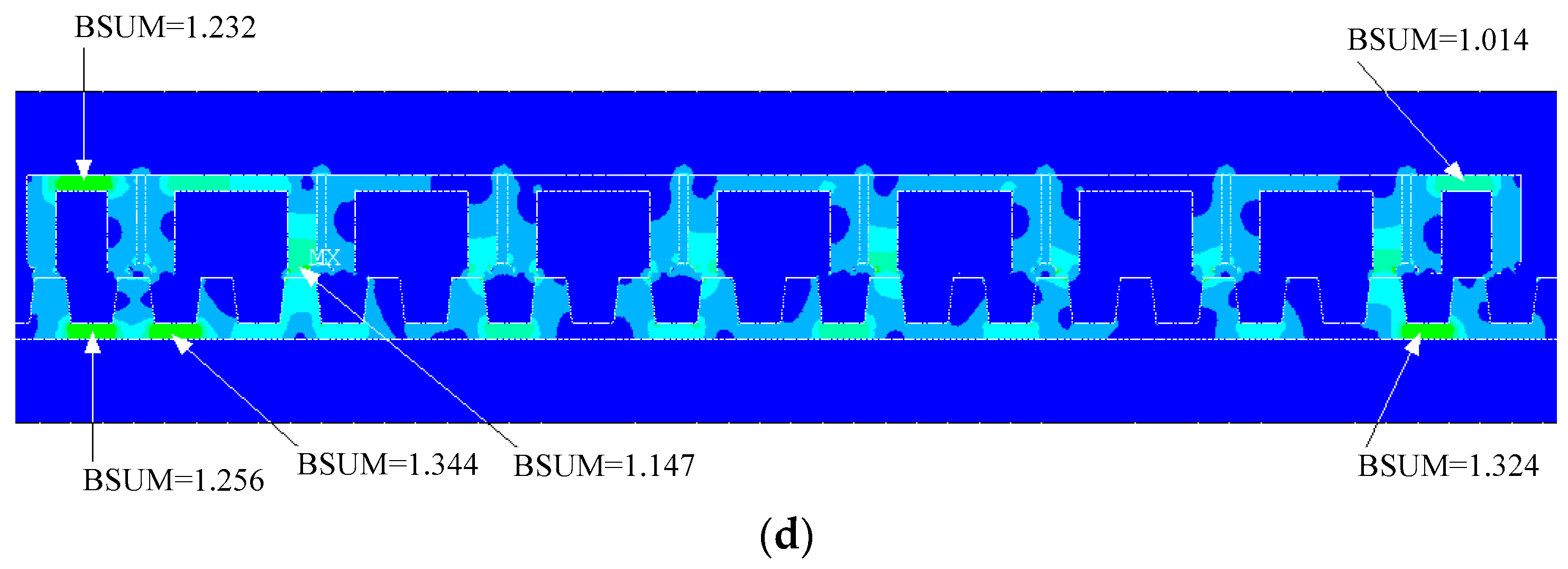
As shown in
Figure 8, due to the passive additional teeth, the flux density values in the secondary side yoke nearby the two end teeth of primary side in Machine II and Machine IV are obviously higher than those in Machine I and Machine III.
3.1. Width of Stator Teeth
First of all, the width of the stator (the secondary side) tooth tip and tooth root, which are shown in
Figure 7, are optimized.
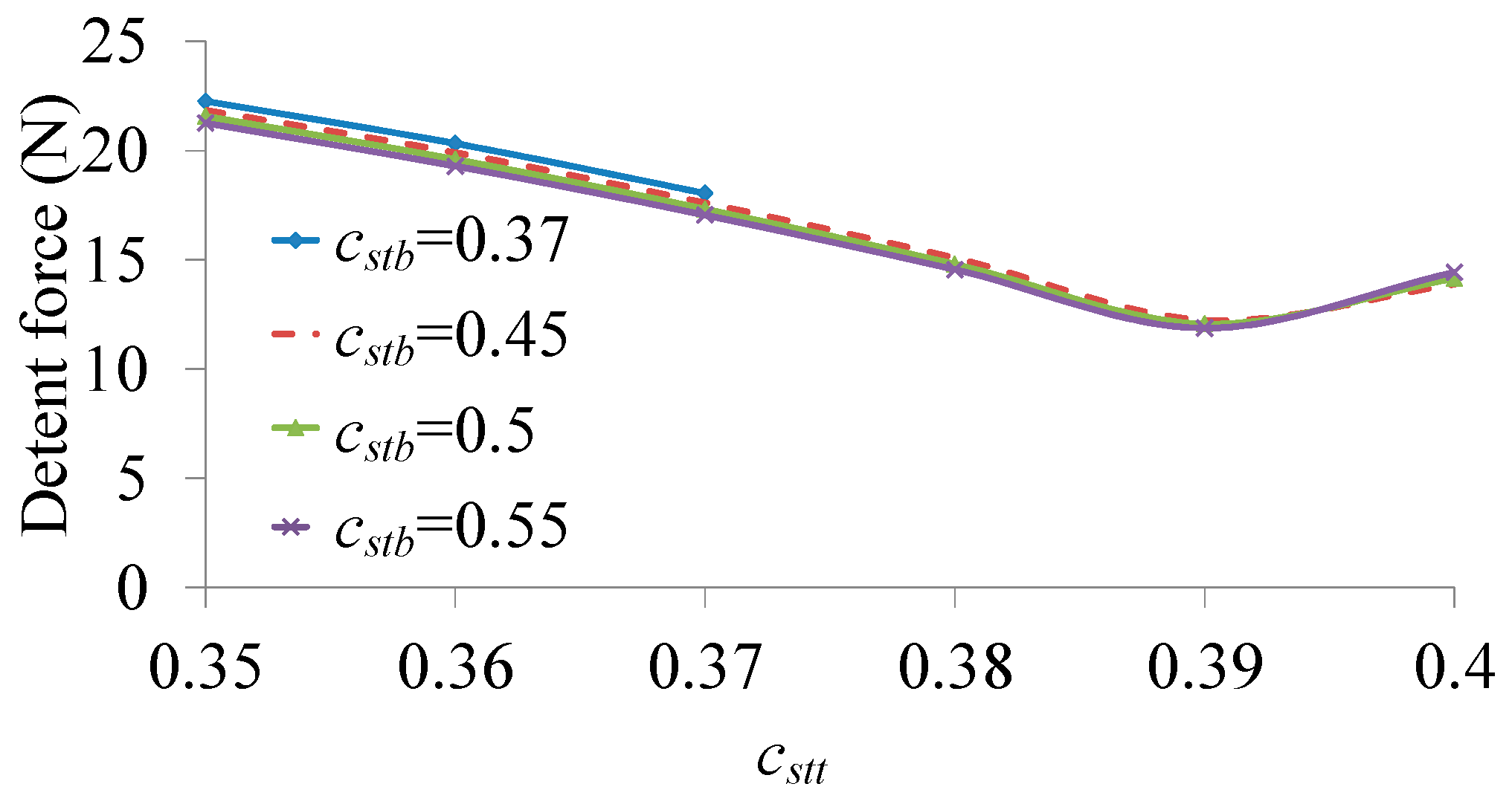
Figure 9 shows the detent force peak-to-peak value of the proposed machine with different
cstt and
cstb, where
cstt is defined as the ratio of the width of stator tooth tip
bstt to the stator tooth pitch
τs, and
cstb is defined as the ratio of the width of stator tooth root
bstb to the stator tooth pitch
τs. It can be found that the detent force achieves the minimum value when
cstt and
cstb equal 0.39 and 0.55, respectively. Actually,
cstb does not have a significant effect on the detent force.
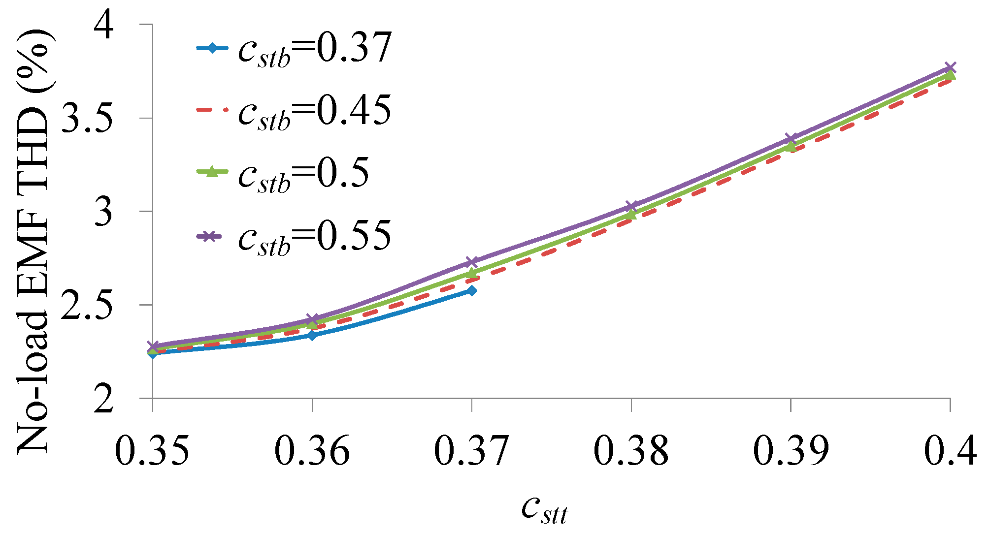
Figure 10 shows the change of the no-load EMF THD with respect to
cstt and
cstb. It indicates that the no-load EMF THD increases with the rise of
cstt. And, the no-load EMF THD is not sensitive to
cstb either.
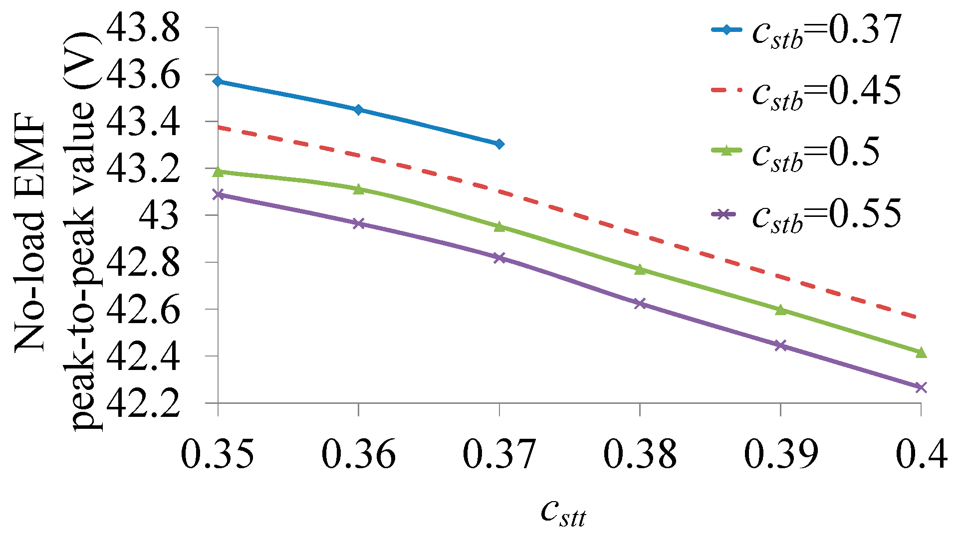
Consequently, the no-load EMF peak-to-peak values with the different
cstt and
cstb are calculated. As shown in
Figure 11, the no-load EMF peak-to-peak value reduces with respect to the increase of
cstt and
cstb, due to the flux leakage around the stator teeth.
Based on
Figure 10 and
Figure 11, a conclusion can be drawn that the better performances of no-load EMF can be achieved when the relatively smaller
cstt and
cstb are adopted. However, the excessive narrow stator teeth will result in serious magnetic saturation when the currents are fed into the armature windings. Thus the thrust force will be restrained and the efficiency of the machine will be reduced. So, the thrust force has to be analyzed to obtain the optimal
cstt and
cstb values taking into account the magnetic field in iron core caused by both of the armature current and the PMs.
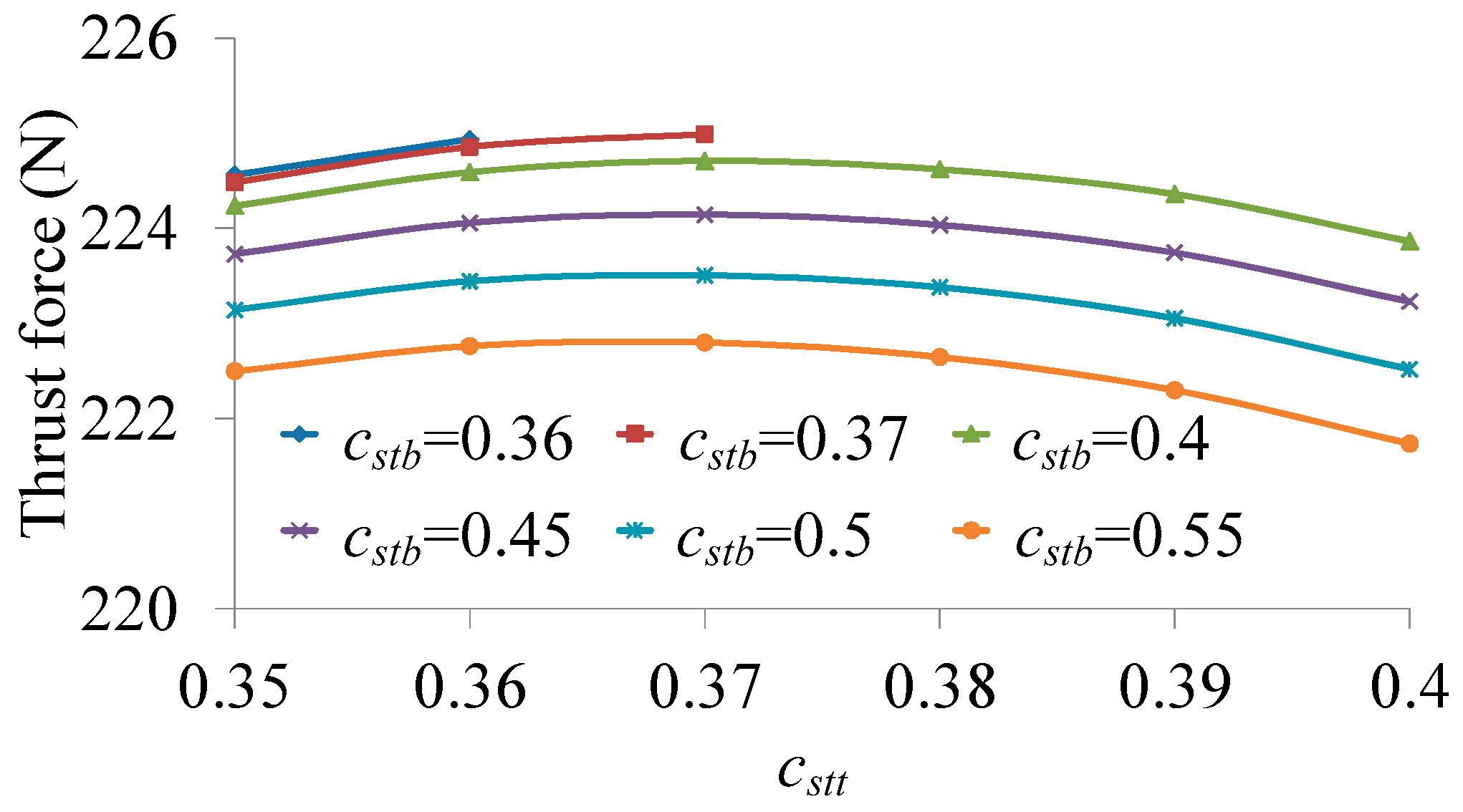
Figure 12 shows the average thrust force values with the different
cstt and
cstb. It can be found that the thrust force improves firstly and then reduces with the increase of
cstt, and reduces with the increase of
cstb. When
cstt = 0.37 and
cstb = 0.37, the thrust force achieves the maximum value which is equal to be about 225 N.
3.2. Width of Side Slot
The multiple additional tooth is composed of an active additional tooth and a traditional passive additional tooth. And the width of the side-slot, which is between the active additional tooth and the passive additional tooth, can be adjusted to optimize the detent force of the C-core LFSPM machine. As shown in
Figure 2d, the width of the side-slot is defined as:
where
wmss is the width of the side-slot,
τs is the pitch of the stator tooth and
css is the ratio between
wmss and
τs.
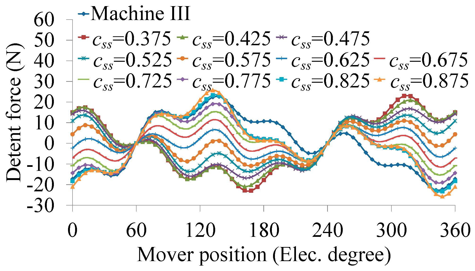
Figure 13 shows the detent force waveforms versus
css when
cstt = 0.37 and
cstb = 0.5. And the peak-to-peak values with the different
css are listed in
Table 1. It can be seen that the detent force peak-to-peak value changes versus
css. When
css = 0.625, as listed using italic numbers, the detent force peak-to-peak value can achieve the minimum value which is 38.3% of that of Machine III.
Defining the active length of the proposed machine as the distance between the midlines of the two passive additional teeth, the active length of the proposed machine can be expressed as:
where
wmt,
wPM and
wmst are the width of the mover tooth, the width of the PM and the width of passive additional tooth, respectively,
τm is the pitch of the mover tooth, and
La is the active length of the proposed machine. Consequently, the width of the side-slot and the active length of the proposed machine can be obtained according to the dimension parameters. As listed in
Table 1, when
css = 0.625, the detent force peak-to-peak value equals 17.32 N, and the width of the side-slot and the active length of the proposed machine are equal to 11.538 mm and 323.077 mm, respectively. It should be noticed that the ratio between
La and
τs is 17.5. In fact, the detent force of the PM linear machine is composed of two components, namely, the slot effect and the end effect. And the adjustment of the width of side-slot is mainly to reduce the end effect detent force. When the active length of the short side of the LFSPM machine equals odd times of half of the stator tooth pitch, the phase difference of the two end effect detent force components caused by each end, respectively, equals 180°. Thus the resultant end effect detent force can be minimized, which is consistent with the FEM result.
4. Electromagnetic Performance Analysis
Based on the optimization design, a 3-phase 6/13-pole C-core LFSPM machine with the multiple teeth is designed. The corresponding key parameters are listed in
Table 2. Then the static characteristics of the proposed machine are analyzed by using the FEM.
Figure 14 shows the 3-phase no-load flux linkage waveforms of four machines. It can be seen that flux linkage peak-to-peak values of Machine III and Machine IV are obviously improved compared with those of the other machines due to the contribution of the active additional teeth PMs. Machine II exhibits the maximum DC components and the most serious asymmetry in its 3-phase flux linkage peak-to-peak values. Furthermore, the asymmetry of Machine IV is effectively restrained, although the DC components are a little bigger than those of Machine I and Machine III. In order to indicate the improvement clearly, the key parameters of the no-load flux linkage are listed in
Table 3.
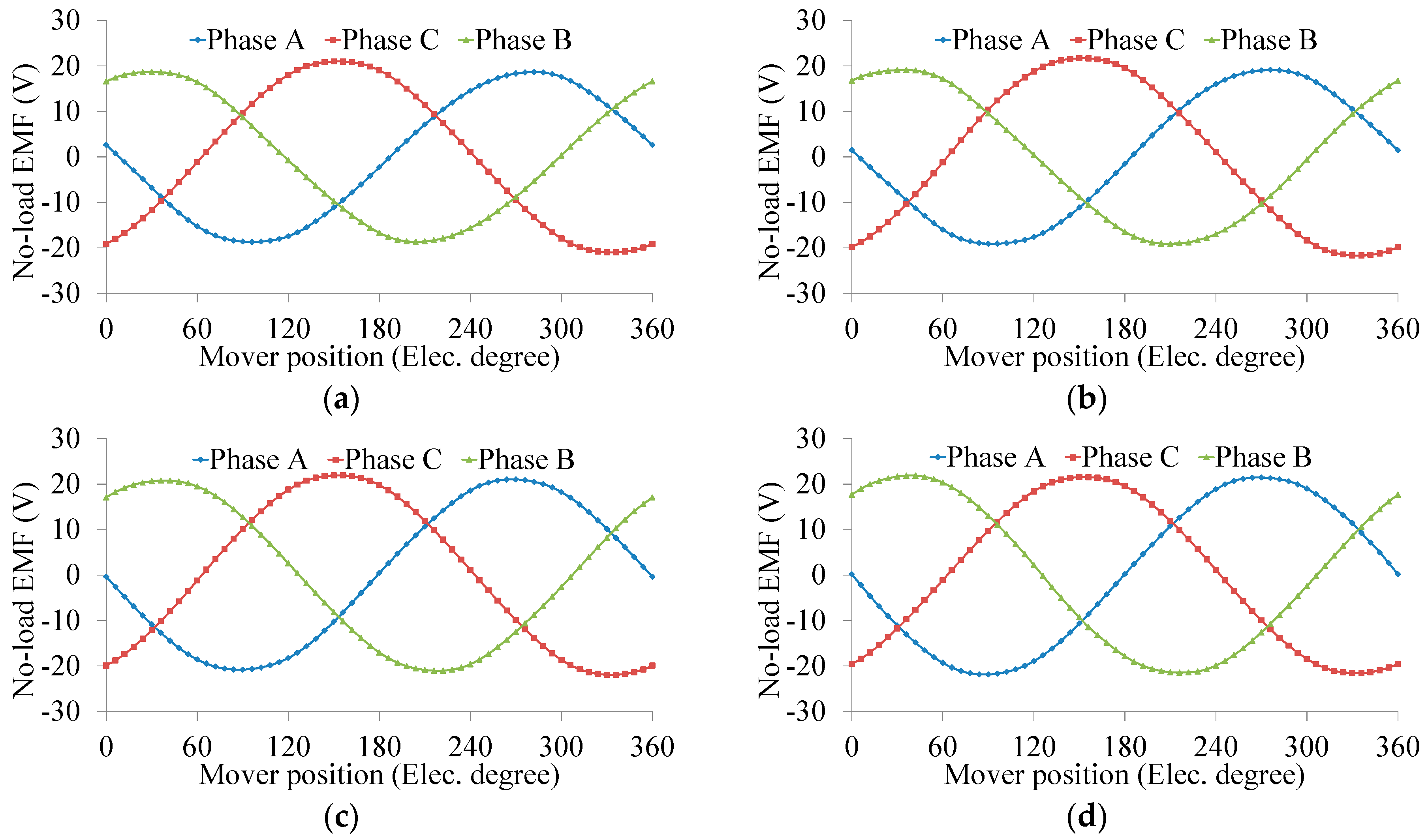
Then the no-load EMF can be obtained by differentiating the flux linkage with respect to time. As shown in
Figure 15, the no-load EMF waveforms of machine IV are also very symmetrical, and the peak-to-peak values of the 3-phase are 43.3 V, 43.1 V and 43 V, respectively.
When the
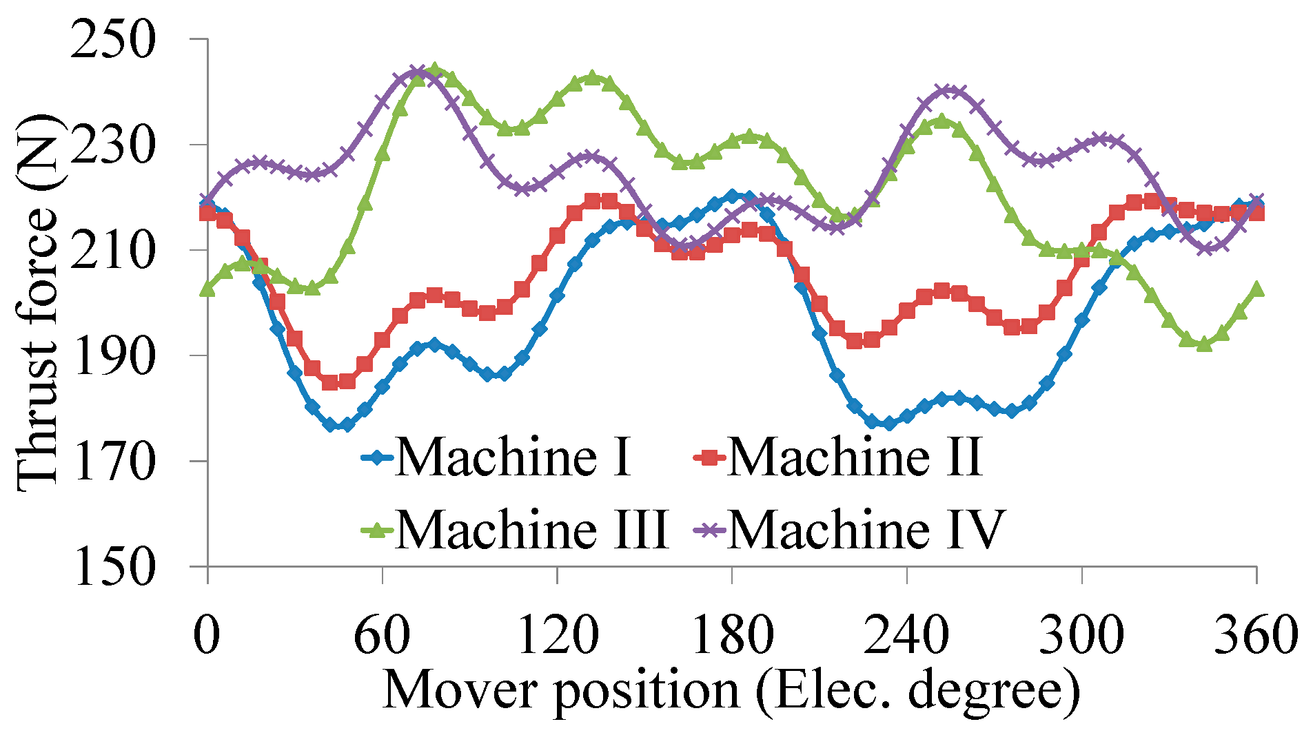
id = 0 control strategy is adopted, namely, the armature currents are in phase with the 3-phase no-load EMF, the thrust force can be calculated.
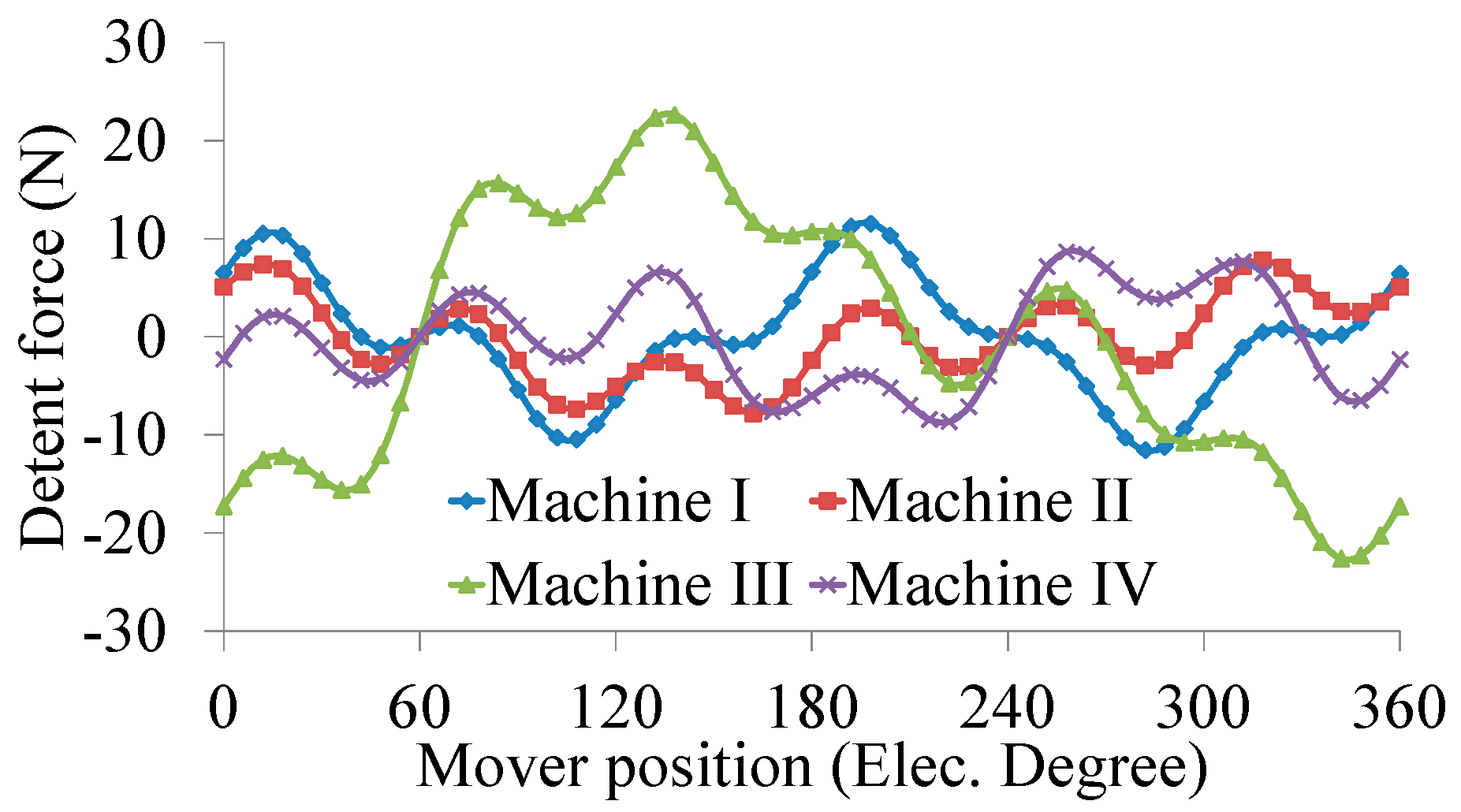
Figure 16 shows the thrust force waveforms of four machines. The detent force waveforms are plotted in
Figure 17.
The corresponding values are compared in
Table 4. It can be seen that Machine IV can achieve the maximum average value and the minimum peak-to-peak value of thrust force. Although the detent force peak-to-peak value of Machine II is a little smaller than that of Machine IV, the thrust ripple is higher than that of Machine IV. The peak-to-peak value of the detent force of Machine IV is 17.32 N, which is less than 8% of the average thrust force.
5. Conclusions
In this paper, a C-core LFSPM machine is proposed for long stroke applications such as cableless elevators. The key of the proposed machine is that two multiple additional teeth are employed at each end of the mover side. The multiple additional teeth are composed of an active additional tooth and a traditional passive additional tooth, in which the function of the active additional tooth is to balance the asymmetric 3-phase magnetic circuit due to the end effect, and the passive additional tooth contributes to reduce the detent force through adjusting the width of side-slot. Based on FEM analysis, the width of stator tooth and the width of side-slot are optimized to achieve high thrust force, low detent force, high no-load EMF THD, and so on. Finally, the average thrust force of 224.99 N and the detent force peak-to-peak value of 17.32 N of proposed machine can be achieved. It should be mentioned that Machine IV possesses the minimum thrust force ripple of 14.88% and the most balanced 3-phase no-load flux linkage among the four machines. It confirms that the end effect of proposed machine is restricted greatly due to multiple additional teeth. However, the thrust force ripple is still high for the stable operation of elevator due to the double tooth structure of FSPM machines, so suitable control strategies, such as the harmonic current injection method can be adopted to provide a lower thrust force ripple. The prototype machine and its experiment results will be presented in a future paper.


