
A Witricity-Based High-Power Device for Wireless Charging of Electric Vehicles


Abstract
:1. Introduction
2. Fundamental Analysis
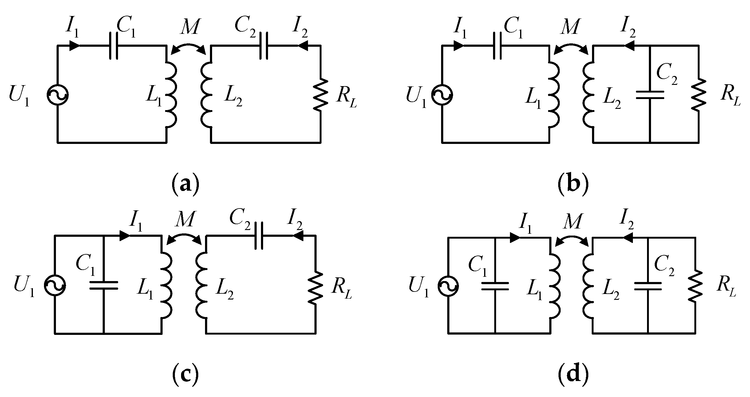
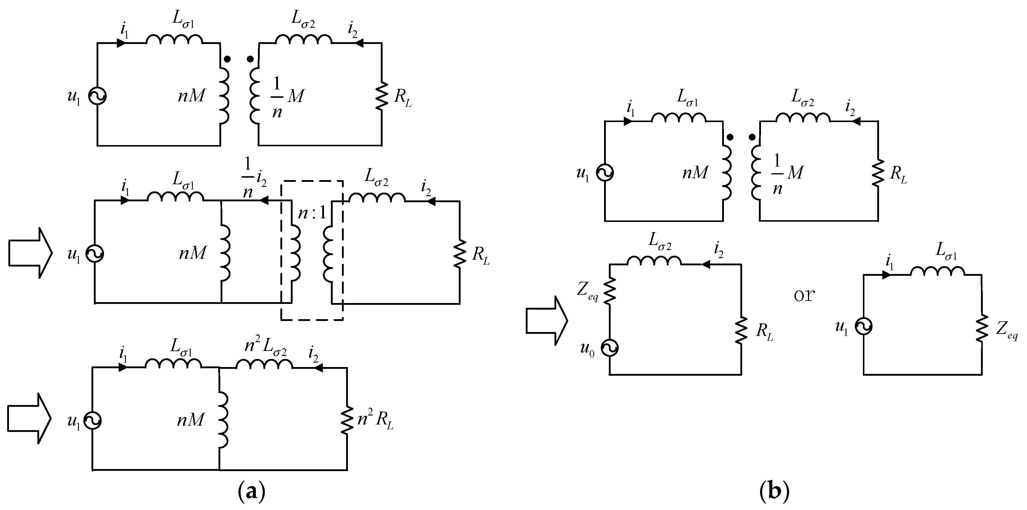
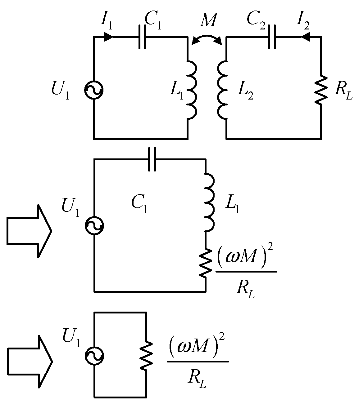
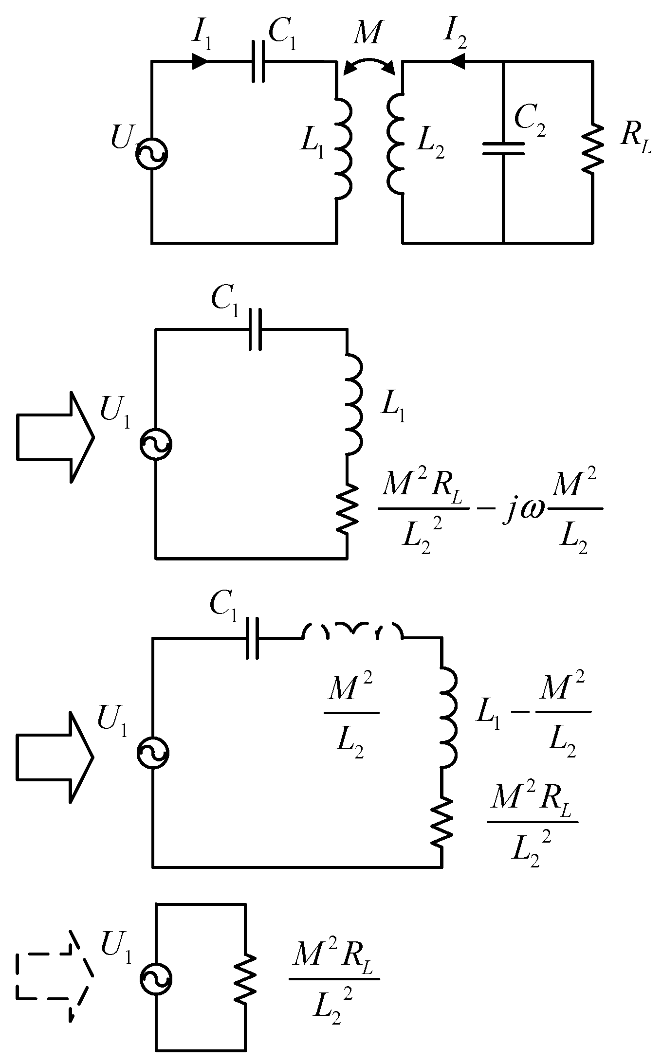
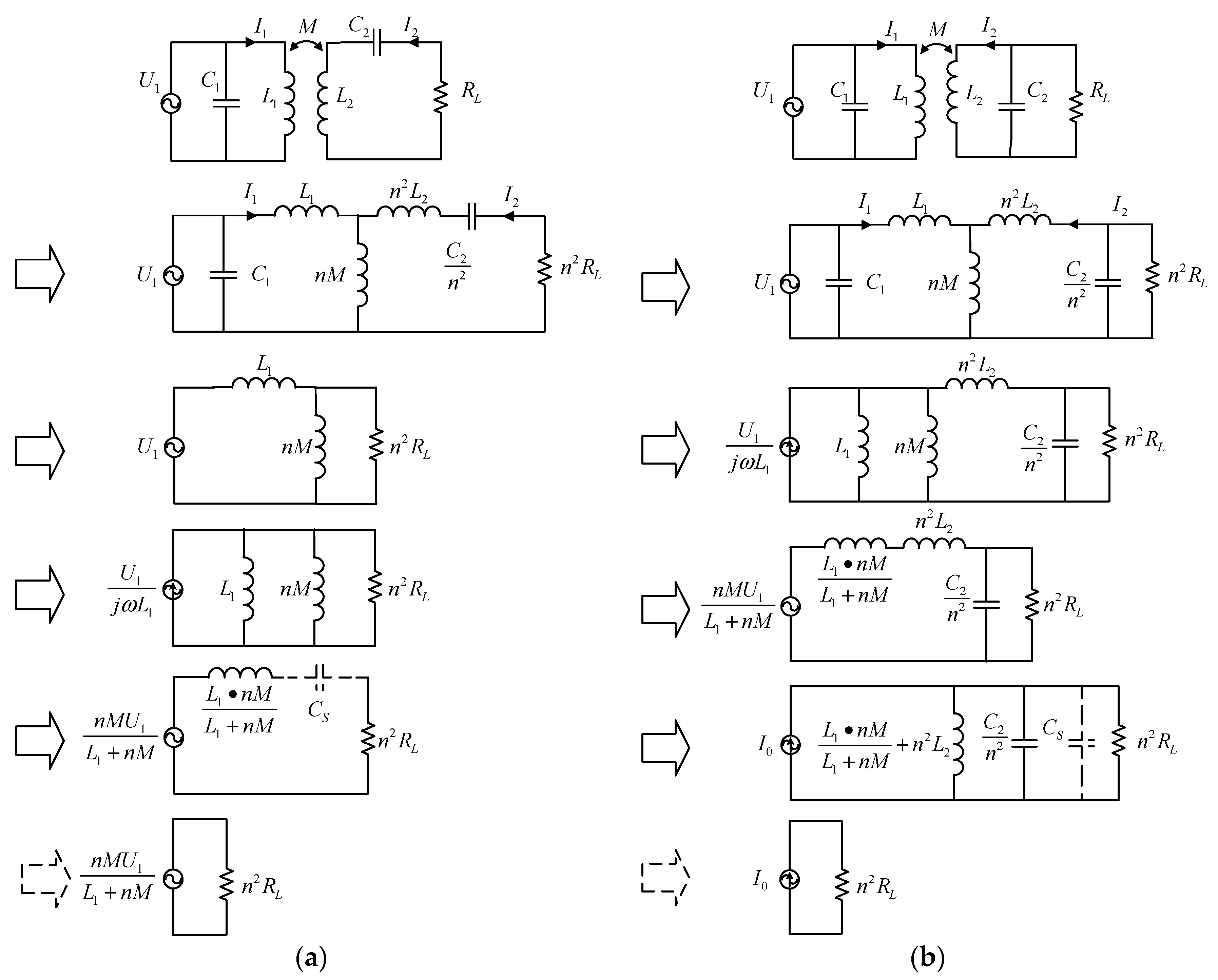
2.1. The SS Compensation Circuit
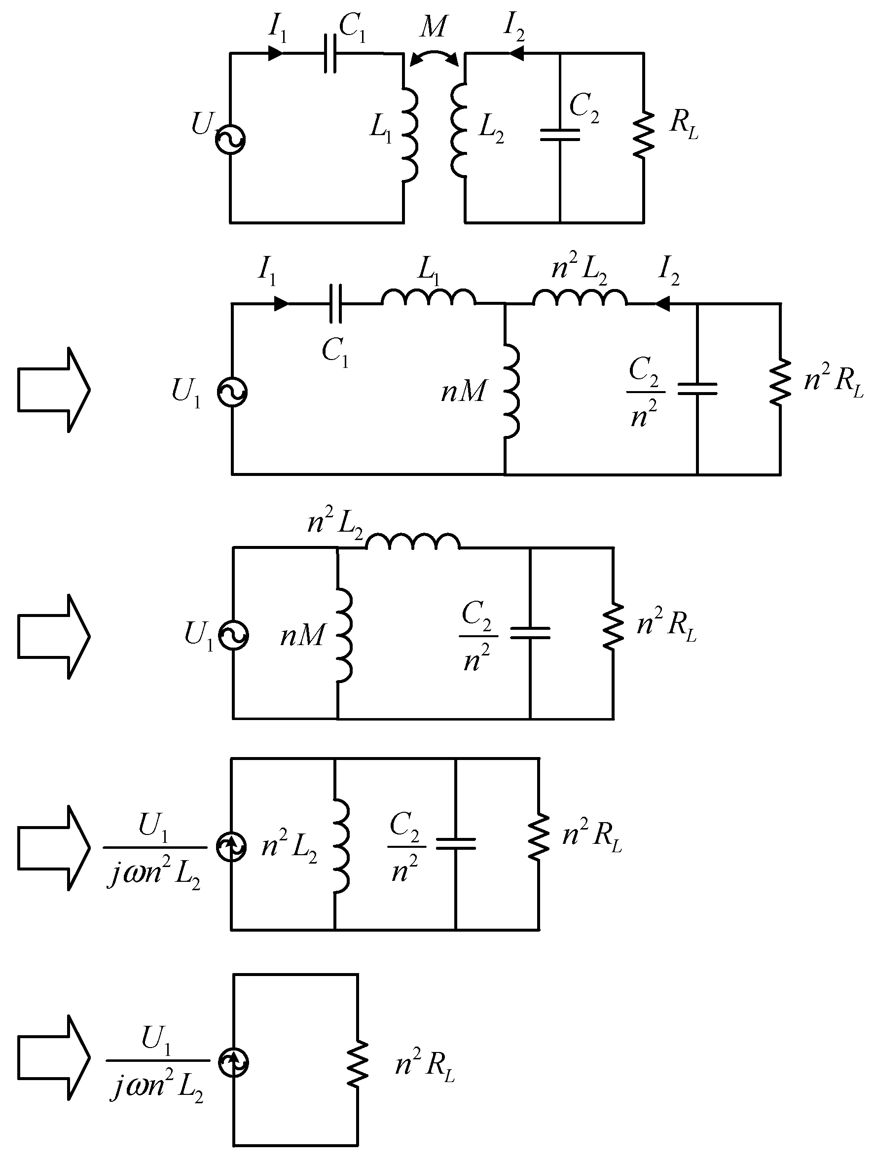
2.2. The SP Compensation Circuit
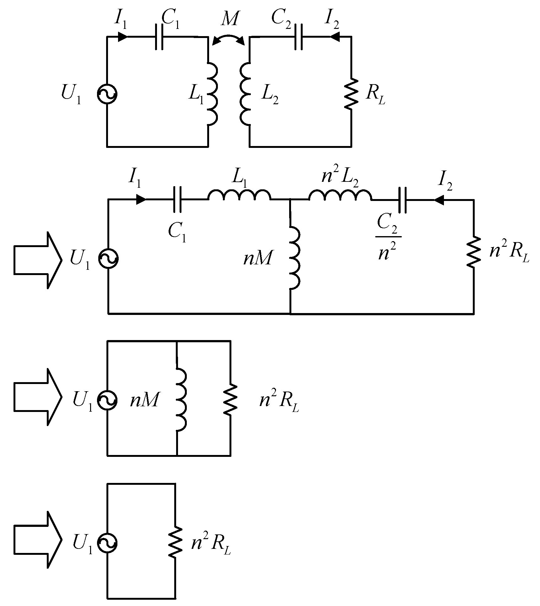
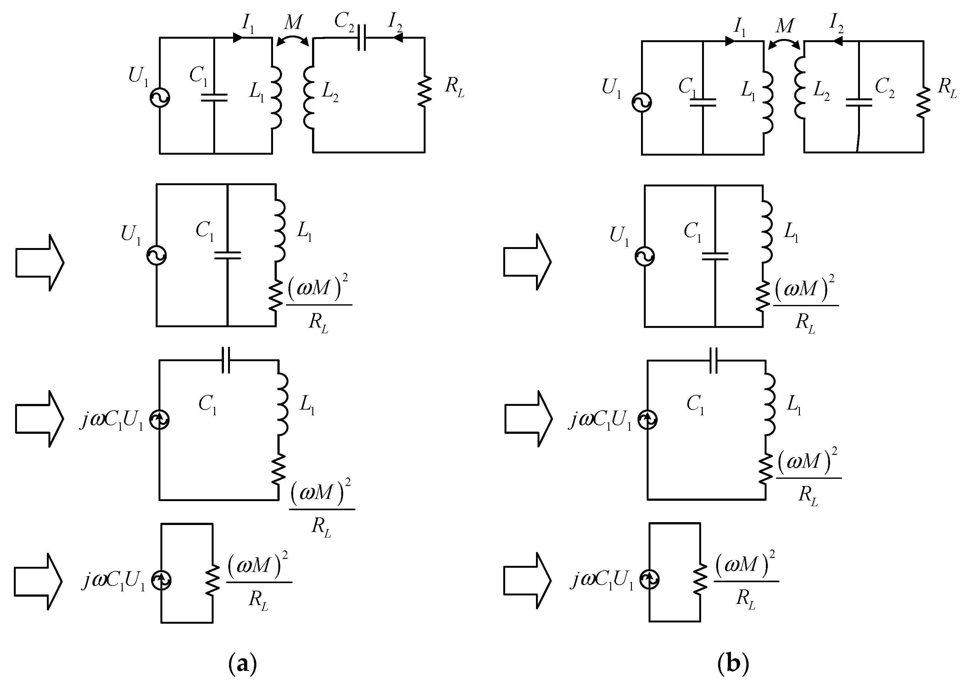
2.3. The PS and PP Compensation Circuit
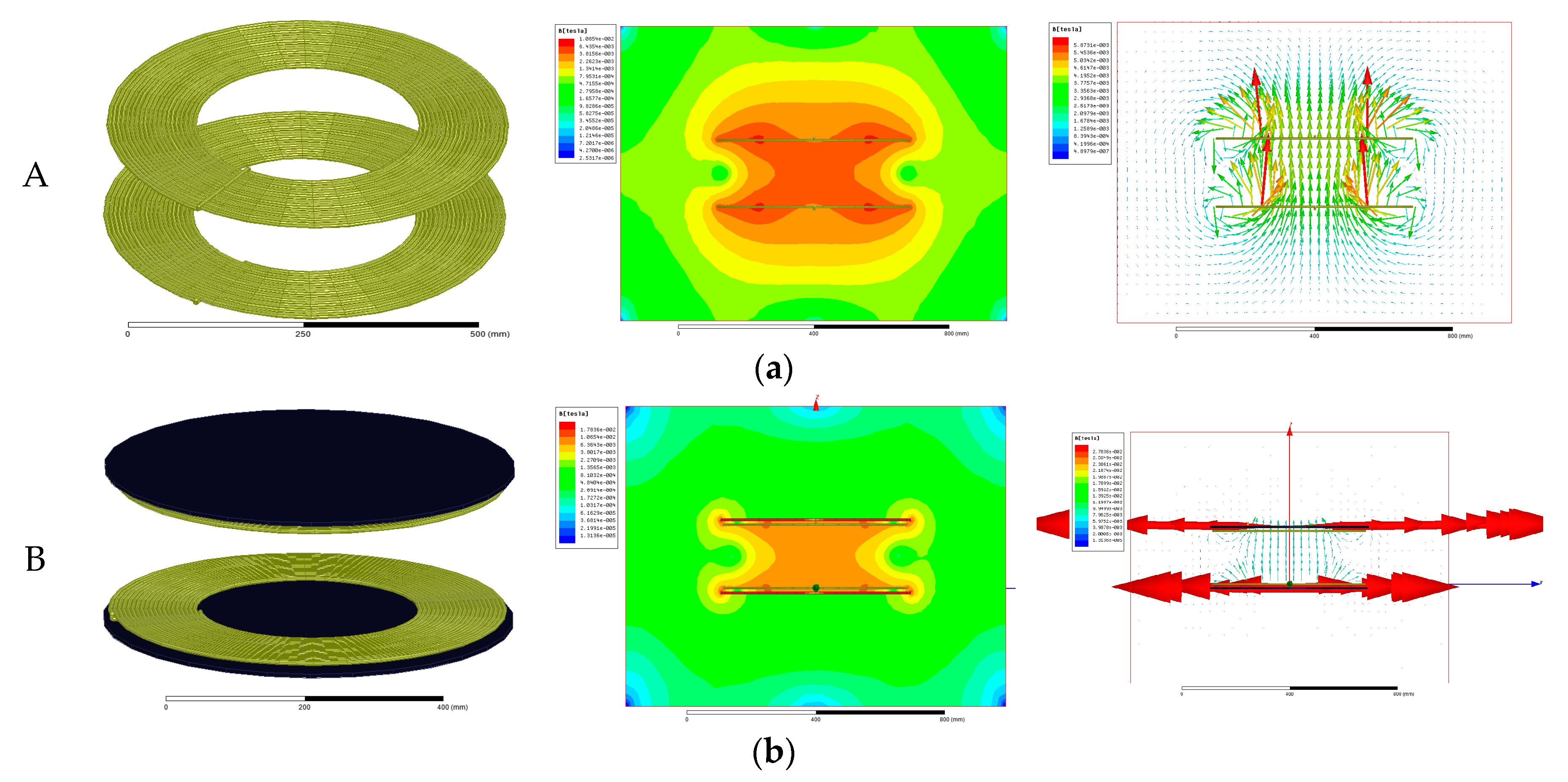
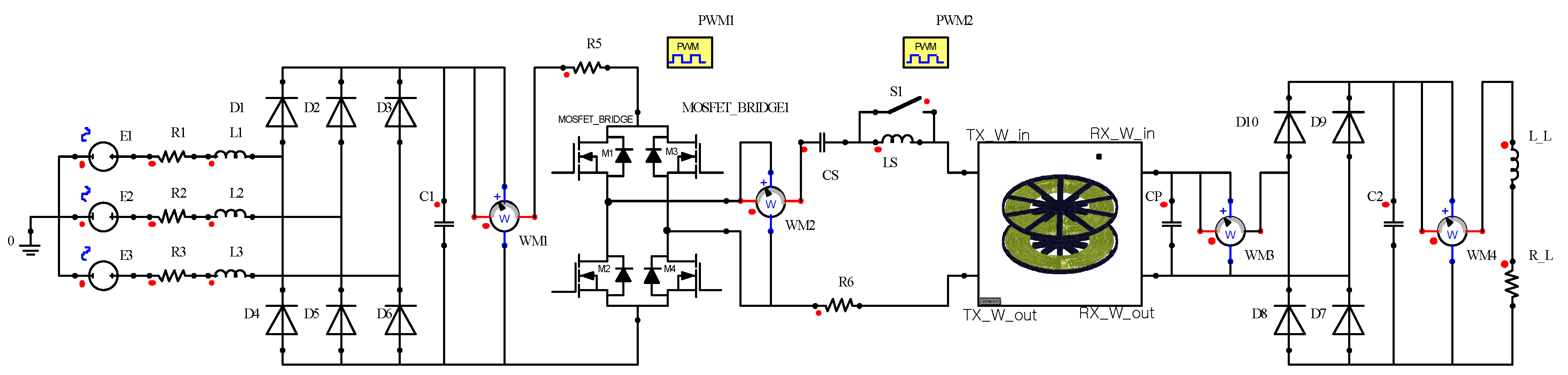
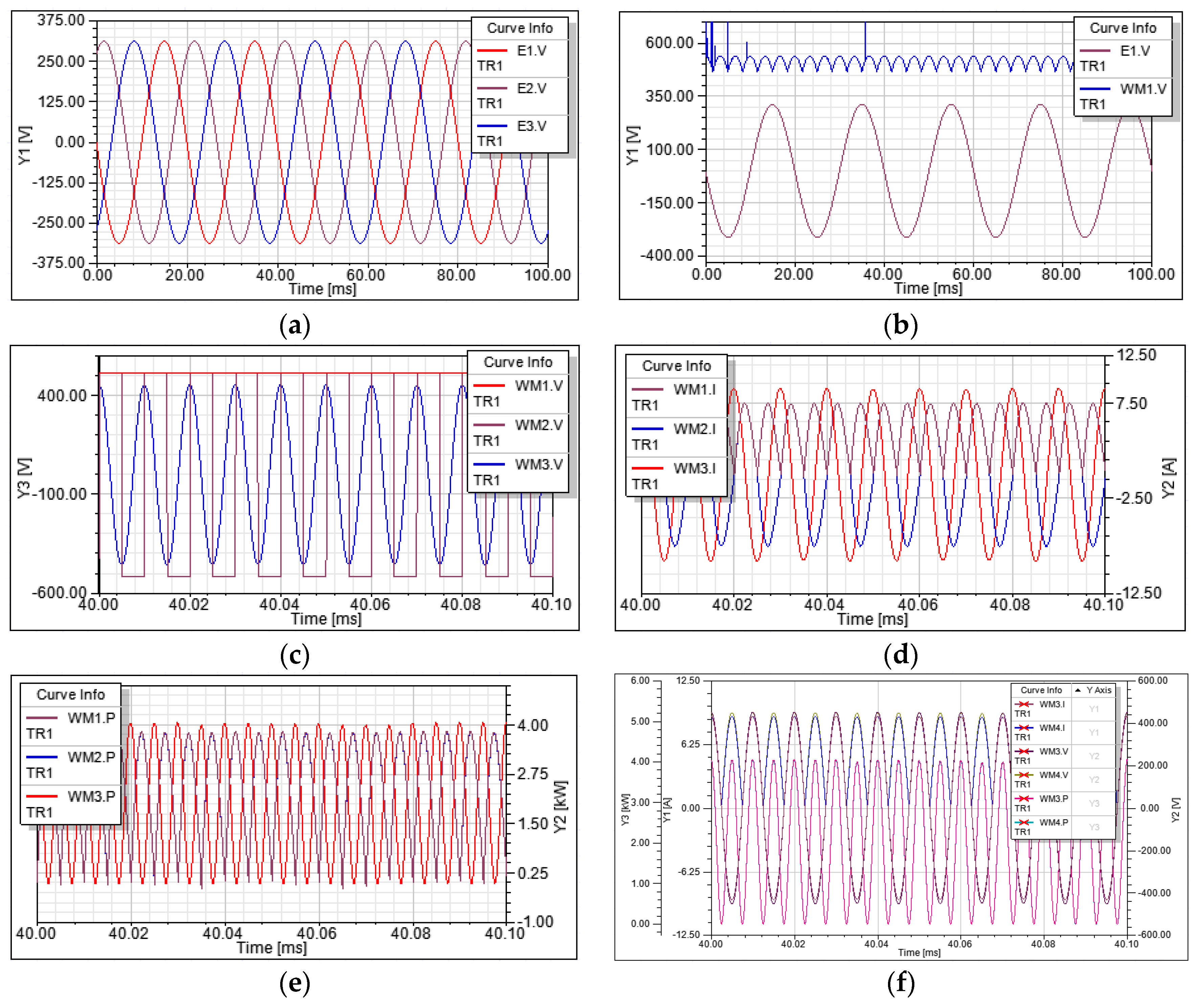
3. Simulation
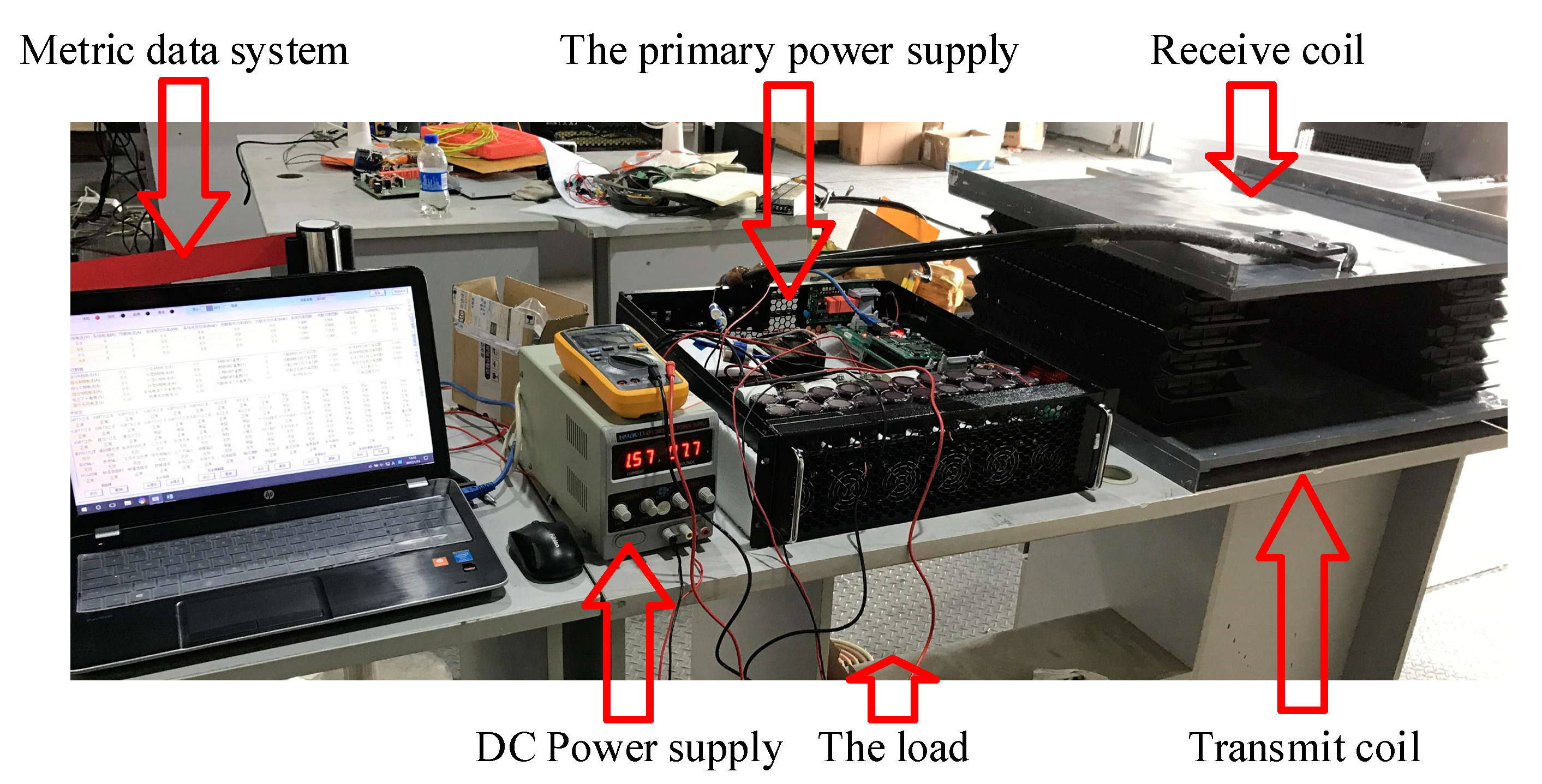
4. Experimental Evaluation
- (a)
- The simulation model, built in an ideal circumstance, has less power loss than the actual circuit.
- (b)
- The electromagnetic shielding effectiveness of the ferrite core, which is made of small blocks, is worse than the whole ferrite core built in Maxwell.
- (c)
- There are measurement error and other extraneous factors affecting the transmission efficiency.
5. Conclusions
Acknowledgments
Author Contributions
Conflicts of Interest
References
- Karalis, A.; Joannopoulos, J.D.; Soljačić, M. Efficient wireless non-radiative mid-range, energy transfer. Ann. Phys. 2008, 323, 34–48. [Google Scholar] [CrossRef]
- Jiang, H.; Zhang, J.; Lan, D.; Chao, K.K.; Liou, S.; Shahnasser, H.; Fechter, R.; Hirose, S.; Harrison, M.; Roy, S. A low-frequency versatile wireless power transfer technology for biomedical implants. IEEE Trans. Biomed. Circuits Syst. 2013, 7, 526–535. [Google Scholar] [CrossRef] [PubMed]
- Nair, V.V.; Choi, J.R. An Integrated Chip High-Voltage Power Receiver for Wireless Biomedical Implants. Energies 2015, 8, 5467–5487. [Google Scholar] [CrossRef]
- Mizuno, K.; Miyakoshi, J.; Shinohara, N. Wireless power transfer using resonant coupling and in vitro study. In Proceedings of the 2014 IEEE General Assembly and Scientific Symposium, Beijing, China, 16–23 August 2014; pp. 97–107.
- Cruciani, S.; Campi, T.; Maradei, F.; Feliziani, M. Numerical simulation of Wireless Power Transfer system to recharge the battery of an implanted cardiac pacemaker. In Proceedings of the International Symposium on Electromagnetic Compatibility, Raleigh, NC, USA, 1–4 September 2014; pp. 44–47.
- Mizuno, K.; Shinohara, N.; Miyakoshi, J. Expression of Heat Shock Proteins in Human Fibroblast Cells under Magnetic Resonant Coupling Wireless Power Transfer. Energies 2015, 8, 12020–12028. [Google Scholar] [CrossRef] [Green Version]
- Tortora, G.; Mulana, F.; Ciuti, G.; Dario, P.; Menciassi, A. Inductive-Based Wireless Power Recharging System for an Innovative Endoscopic Capsule. Energies 2015, 8, 10315–10334. [Google Scholar] [CrossRef]
- Rao, S.; Chiao, J.C. Body Electric: Wireless Power Transfer for Implant Applications. IEEE Microw. Mag. 2015, 16, 54–64. [Google Scholar] [CrossRef]
- Chen, W.; Liu, C.; Lee, C.; Shan, Z. Cost-Effectiveness Comparison of Coupler Designs of Wireless Power Transfer for Electric Vehicle Dynamic Charging. Energies 2016, 9, 906. [Google Scholar] [CrossRef]
- Song, X.; Liu, G.; Chao, Z.; Xia, H.; Zhang, R.U.; Xu, X.Y. Resonance Wireless Charging Technology in Separate Groups for the Power Battery Packs of Electric Buses. Diangong Jishu Xuebao 2013, 28, 92–98. [Google Scholar]
- Hou, C.C.; Chang, K.Y. Inductive Power Transfer Systems for Bus-Stop-Powered Electric Vehicles. Energies 2016, 9, 512. [Google Scholar] [CrossRef]
- Jang, Y.J.; Jeong, S.; Min, S.L. Initial Energy Logistics Cost Analysis for Stationary, Quasi-Dynamic, and Dynamic Wireless Charging Public Transportation Systems. Energies 2016, 9, 483. [Google Scholar] [CrossRef]
- Naberezhnykh, D.; Theodoropoulos, T.; Reed, N.; Ognissanto, F.; Bludszuweit, H. Operational requirements for dynamic wireless power transfer systems for electric vehicles. In Proceedings of the IEEE Electric Vehicle Conference, Florence, Italy, 17–19 December 2014; pp. 1–8.
- Batra, T.; Schaltz, E.; Ahn, S. Reduction of magnetic emission by increasing secondary side capacitor for ferrite geometry based series-series topology for wireless power transfer to vehicles. In Proceedings of the European Conference on Power Electronics and Applications, Lappeenranta, Finland, 26–28 August 2014; pp. 1–11.
- Li, S.; Mi, C.C. Wireless Power Transfer for Electric Vehicle Applications. IEEE J. Emerg. Sel. Top. Power Electron. 2015, 3, 4–17. [Google Scholar]
- Shekhar, A.; Prasanth, V.; Bauer, P.; Bolech, M. Economic Viability Study of an On-Road Wireless Charging System with a Generic Driving Range Estimation Method. Energies 2016, 9, 76. [Google Scholar] [CrossRef]
- Wang, Z.; Wei, X.; Dai, H. Design and Control of a 3 kW Wireless Power Transfer System for Electric Vehicles. Energies 2015, 9, 10. [Google Scholar] [CrossRef]
- Gao, Y.; Farley, K.B.; Tse, Z.T.H. A Uniform Voltage Gain Control for Alignment Robustness in Wireless EV Charging. Energies 2015, 8, 8355–8370. [Google Scholar] [CrossRef]
- Budhia, M.; Boys, J.T.; Covic, G.; Huang, C.-Y. Development of a Single-Sided Flux Magnetic Coupler for Electric Vehicle IPT Charging Systems. IEEE Trans. Ind. Electron. 2013, 60, 318–328. [Google Scholar] [CrossRef]


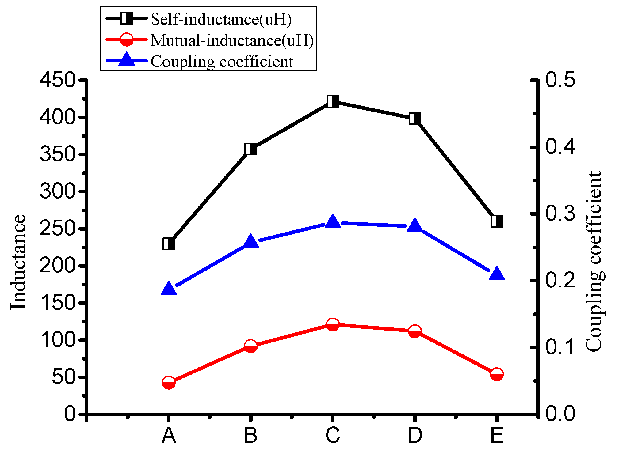
| Name | Self-Inductance () | Mutual-Inductance () | Coupling Coefficient |
|---|---|---|---|
| A | 229.63 | 42.692 | 0.186 |
| B | 357.37 | 91.931 | 0.257 |
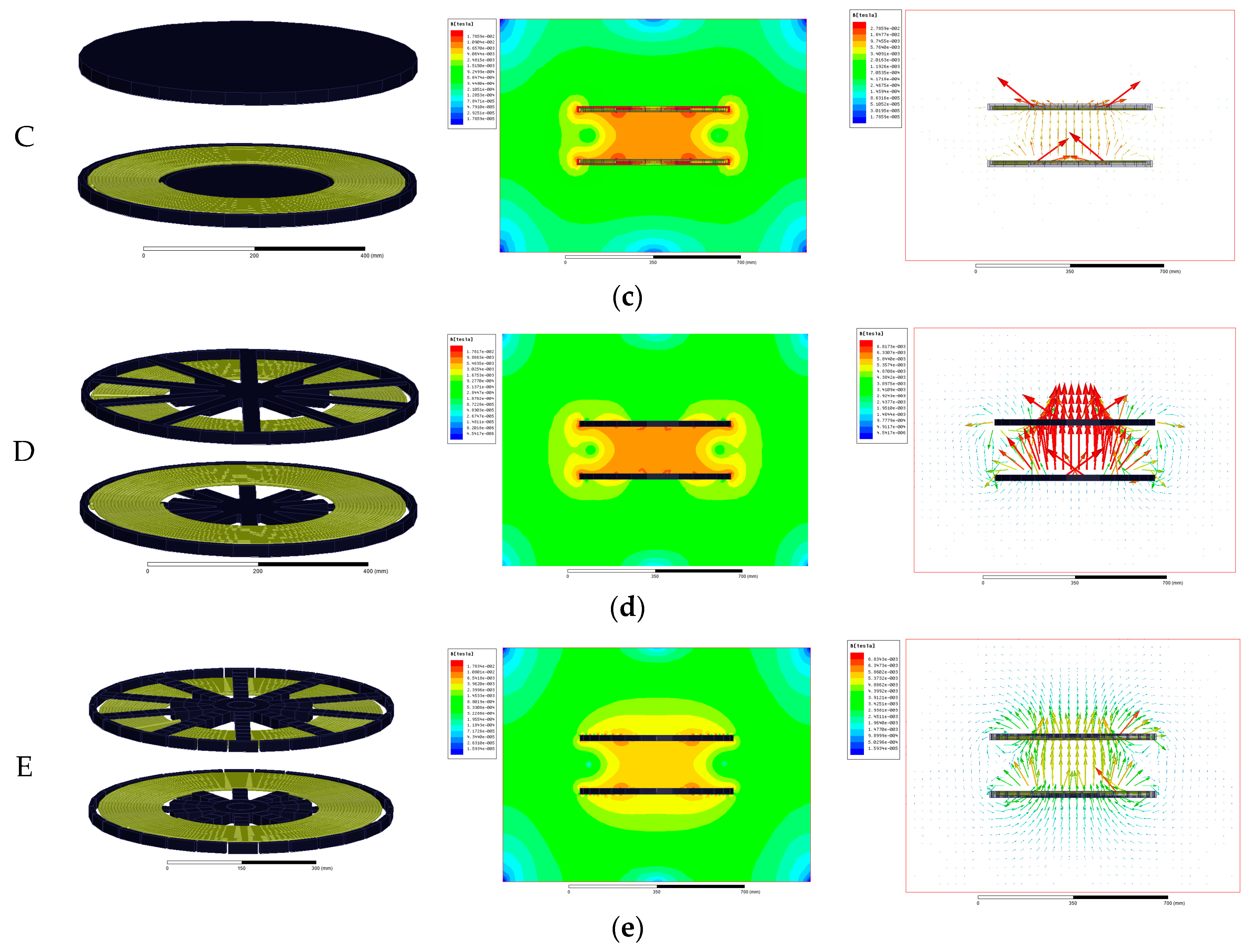
| C | 421.32 | 121.08 | 0.287 |
| D | 398.38 | 111.92 | 0.281 |
| E | 259.98 | 53.978 | 0.208 |
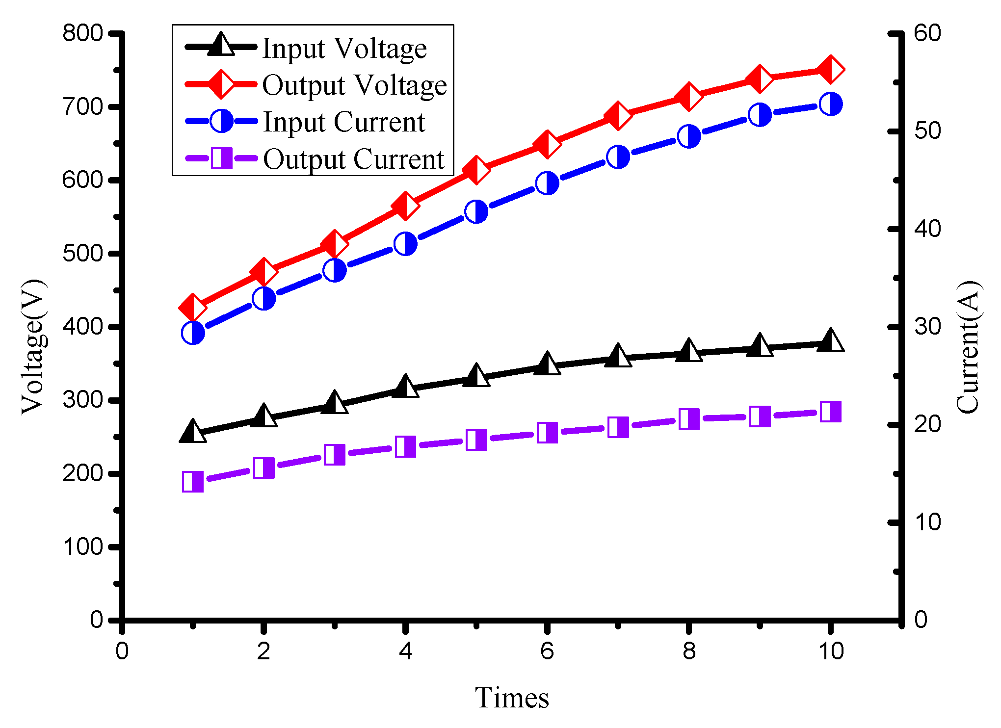
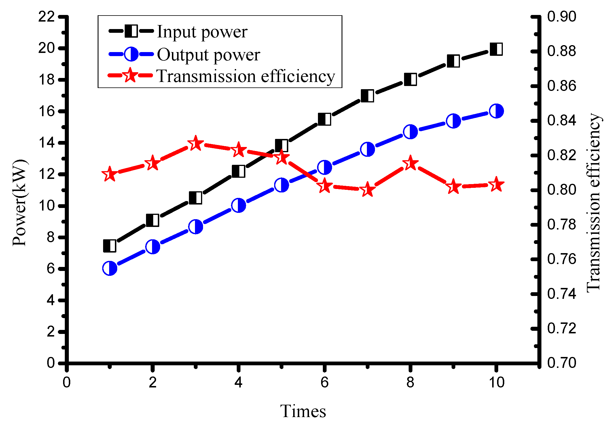
| Input Voltage (V) | Input Current (A) | Input Power (kW) | Output Voltage (V) | Output Current (A) | Output Power (kW) | Transmission Efficiency |
|---|---|---|---|---|---|---|
| 254 | 29.4 | 7.47 | 426 | 14.18 | 6.04 | 80.91% |
| 275 | 32.9 | 9.08 | 475 | 15.59 | 7.40 | 81.55% |
| 293 | 35.8 | 10.5 | 513 | 16.93 | 8.68 | 82.69% |
| 315 | 38.5 | 12.19 | 565 | 17.77 | 10.03 | 82.31% |
| 330 | 41.8 | 13.82 | 614 | 18.46 | 11.32 | 81.88% |
| 346 | 44.7 | 15.5 | 649 | 19.18 | 12.44 | 80.24% |
| 357 | 47.4 | 16.98 | 688 | 19.76 | 13.59 | 80.02% |
| 364 | 49.5 | 18.03 | 714 | 20.59 | 14.70 | 81.55% |
| 371 | 51.7 | 19.19 | 738 | 20.86 | 15.39 | 80.19% |
| 378 | 52.8 | 19.95 | 751 | 21.34 | 16.02 | 80.32% |
© 2017 by the authors. Licensee MDPI, Basel, Switzerland. This article is an open access article distributed under the terms and conditions of the Creative Commons Attribution (CC BY) license ( http://creativecommons.org/licenses/by/4.0/).
Share and Cite
Dai, Z.; Wang, J.; Long, M.; Huang, H. A Witricity-Based High-Power Device for Wireless Charging of Electric Vehicles. Energies 2017, 10, 323. https://doi.org/10.3390/en10030323
Dai Z, Wang J, Long M, Huang H. A Witricity-Based High-Power Device for Wireless Charging of Electric Vehicles. Energies. 2017; 10(3):323. https://doi.org/10.3390/en10030323
Chicago/Turabian StyleDai, Zhongyu, Junhua Wang, Mengjiao Long, and Hong Huang. 2017. "A Witricity-Based High-Power Device for Wireless Charging of Electric Vehicles" Energies 10, no. 3: 323. https://doi.org/10.3390/en10030323