Article

Effects of Syngas Cooling and Biomass Filter Medium on Tar Removal

1
Environmental Science Graduate Program, Oklahoma State University, Stillwater, OK 74078, USA
2
Biobased Products and Energy Center, Oklahoma State University, Stillwater, OK 74078, USA
3
Biosystems and Agricultural Engineering, Oklahoma State University, Stillwater, OK 74078, USA
*
Author to whom correspondence should be addressed.
Energies 2017, 10(3), 349; https://doi.org/10.3390/en10030349
Submission received: 19 December 2016 / Revised: 21 February 2017 / Accepted: 6 March 2017 / Published: 11 March 2017
(This article belongs to the Special Issue Woody Biomass for Bioenergy Production)

Abstract

:
Biomass gasification is a proven technology; however, one of the major obstacles in using product syngas for electric power generation and biofuels is the removal of tar. The purpose of this research was to develop and evaluate effectiveness of tar removal methods by cooling the syngas and using wood shavings as filtering media. The performance of the wood shavings filter equipped with an oil bubbler and heat exchanger as cooling systems was tested using tar-laden syngas generated from a 20-kW downdraft gasifier. The tar reduction efficiencies of wood shavings filter, wood shavings filter with heat exchanger, and wood shavings filter with oil bubbler were 10%, 61%, and 97%, respectively.

Graphical Abstract

1. Introduction

Conventional fuels such as coal, oil, and natural gas have significant negative environmental impacts and cannot be used on sustainable basis. These concerns have helped shift energy consumption towards renewable and environment friendly sources like biomass-derived energy [1]. Energy from biomass materials are obtained either by direct burning or conversion into liquid or gaseous fuels for practical applications. Technologies such as combustion, gasification, pyrolysis, hydrothermal liquefaction, and fermentation are successfully developed, while few are either commercialized or are under development that convert biomass into useful forms of energy. Among these technologies, gasification offers flexibility in feedstock selection (e.g., agricultural and forest residues, byproducts of food industry and bio-refineries, organic municipal waste), and the product gases (syngas) can be used as fuel to produce heat and electricity. Hence, the gasification is considered one of the most promising technologies [2,3] that utilizes biomass for energy production [4]. Compared to direct combustion, gasification has distinct advantages, such as increased power generation efficiency (up to a 60% increase) and the ability to use the syngas for products other than electricity [5,6].
Biomass gasification is a proven technology and converts carbonaceous materials into syngas, which consists of hydrogen (H2), carbon monoxide (CO), and carbon dioxide (CO2) with methane (CH4), water (H2O), and higher hydrocarbons (HC) in minor quantities [4,7]. The application of syngas includes electricity generation using internal combustion (IC) engines and gas turbines and production of chemicals and liquid fuels [8]. Regardless of many advantages of biomass gasification and wide application of syngas, commercial acceptability of the technology still faces challenges due to difficulty in cleaning the produced syngas [8]. Impurities—such as tars, particulate matters, sulfur, and ammonia—are produced during gasification and entrained in the syngas. In most applications, these impurities must be removed before using syngas. Among these contaminants, tar is a big challenge.
Tar forms during condensation of syngas, and is classified as primary, secondary, and tertiary. Formation of primary tars, in the pyrolysis step, occurs at low temperatures (below 500 °C). In the oxidation step, with increase in temperature (above 500 °C), the primary tars transform and begin to rearrange as secondary tars. Further increase in temperature (above 800 °C) leads to formation of tertiary tars [4]. Tar consists of a wide range of hydrocarbons that can cause blockage in the downstream equipment, engine, and compressors [9,10,11]. The composition and quantity of tar in syngas depends upon gasification conditions and feedstock properties [2]. The acceptable limit varies depending on the application as shown in Table 1 [9,10,11,12].
Removal of tar from the syngas is done either by chemical methods, such as catalytic and thermal cracking [5,13,14], which are expensive to operate [5,15] or by physical methods, such as wet scrubbers and water spray, which have issues with disposing tar mixed solvents [15,16,17]. Besides disposal of tar-mixed solvent, major disadvantages of using a wet cleaning system include decrease in heating value of the producer gas and the net energy efficiency. Therefore, development of tar removal technology with low cost, minimal disposal issues, and high efficiency are instrumental for future of gasification-based technologies [5,16]. Biomass-based dry filters could be an economical and environmental friendly option. Biomass-based filters using corn cobs, wood shavings, and dry coconut coir, charcoal and saw dust have been explored [17,18,19]. Corn cobs and woodchips reduced the tar content to 2 g/Nm3 [18]. To further improve tar removal, other studies have used forms of direct cooling system, including wet scrubbers and water spray towers, before a dry biomass filter [15,16,17]. However, wet cleaning systems require expensive waste water treatment, so safe discharge of the tar mixed solution is a challenge [15,16,17]. A series of heat exchangers [20,21,22] and oil scrubber [23,24,25,26,27] have shown to be effective in reducing tar to as low as 10 mg/Nm3. The tar collected from the heat exchanger and used oil from the oil scrubber can be recycled back to the gasifier [28,29], which eliminates waste effluent treatment. A cleaning system equipped with an indirect cooling system that eliminates waste effluent treatment process and filter mediums which can be reused as gasifier feedstock is a promising alternative to conventional cleaning technologies. However, dry biomass-based filter systems are not tested in combination with indirect cooling system (heat exchanger) or oil scrubber.
The goal of this study was to improve tar removal efficiencies of a dry biomass-based filter in combination with a heat exchanger and oil bubbler. The tar removal efficiencies were evaluated with three filtering methods: (i) wood shavings filter; (ii) wood shavings filter after cooling with a heat exchanger; and (iii) wood shavings filter after cooling with an oil bubbler.

2. Materials and Methods

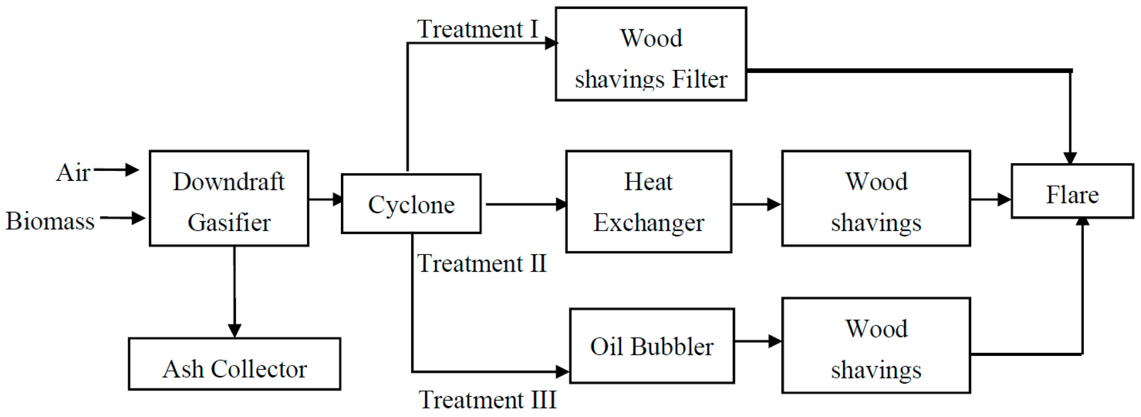
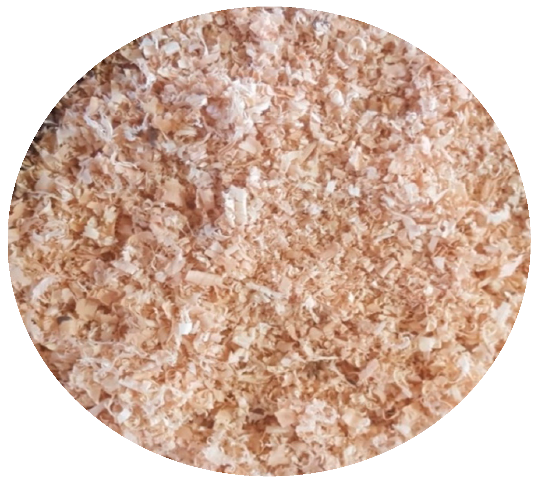
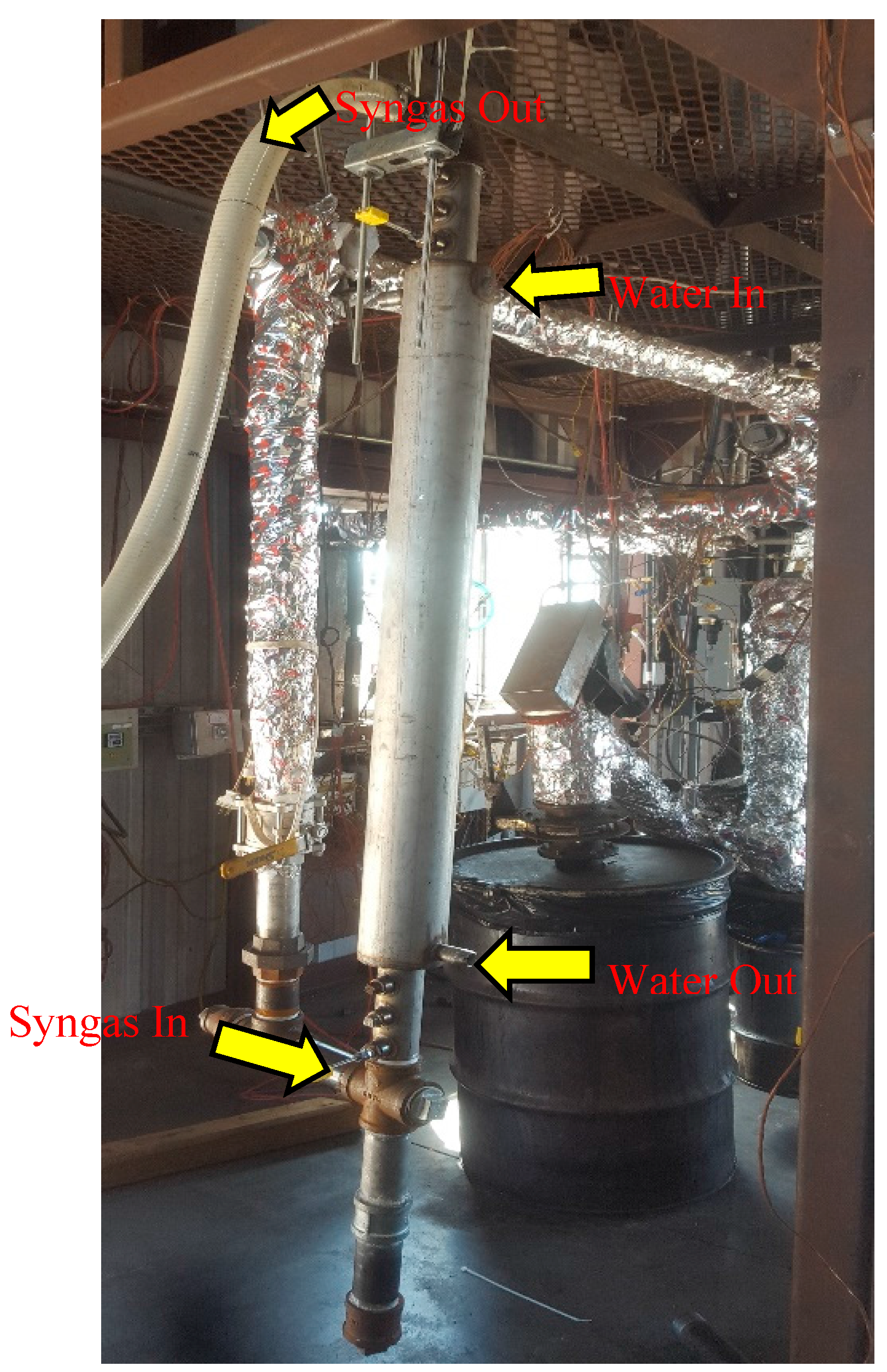
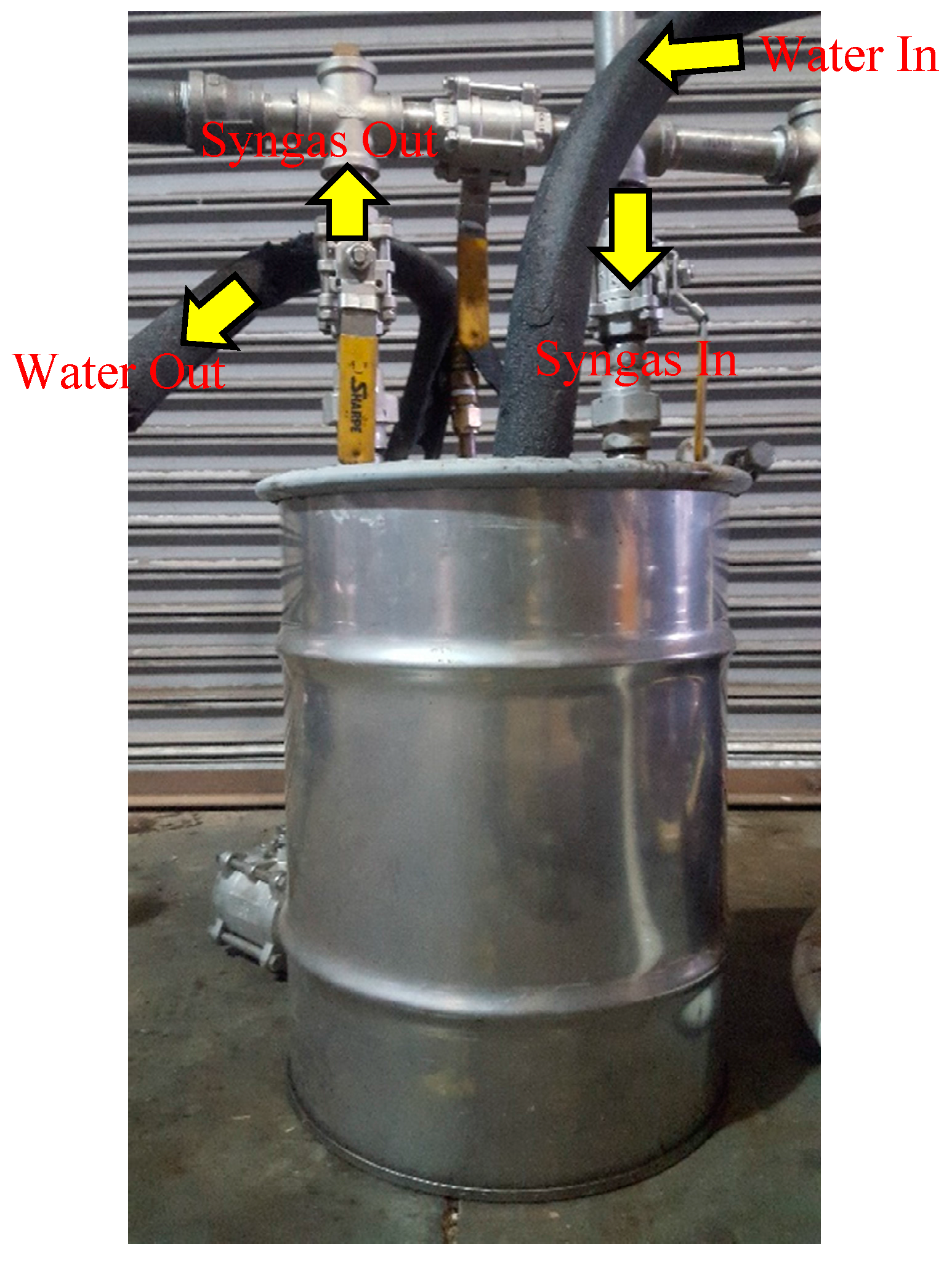
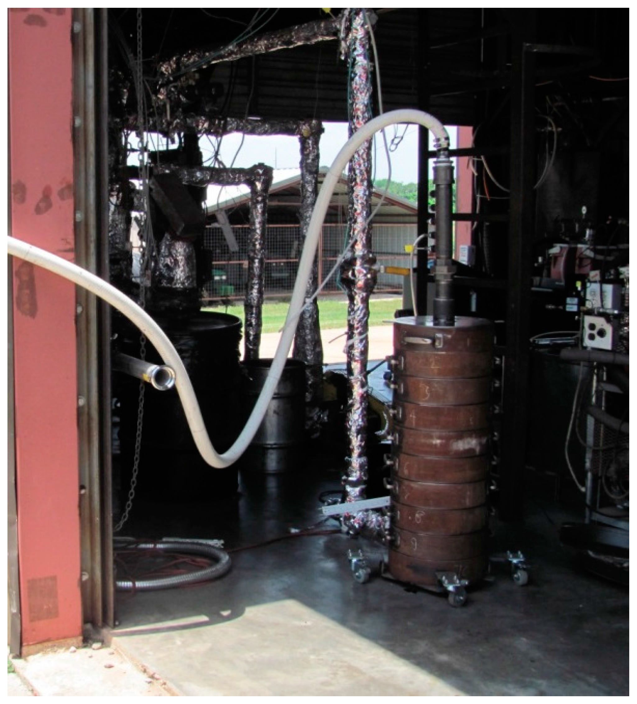
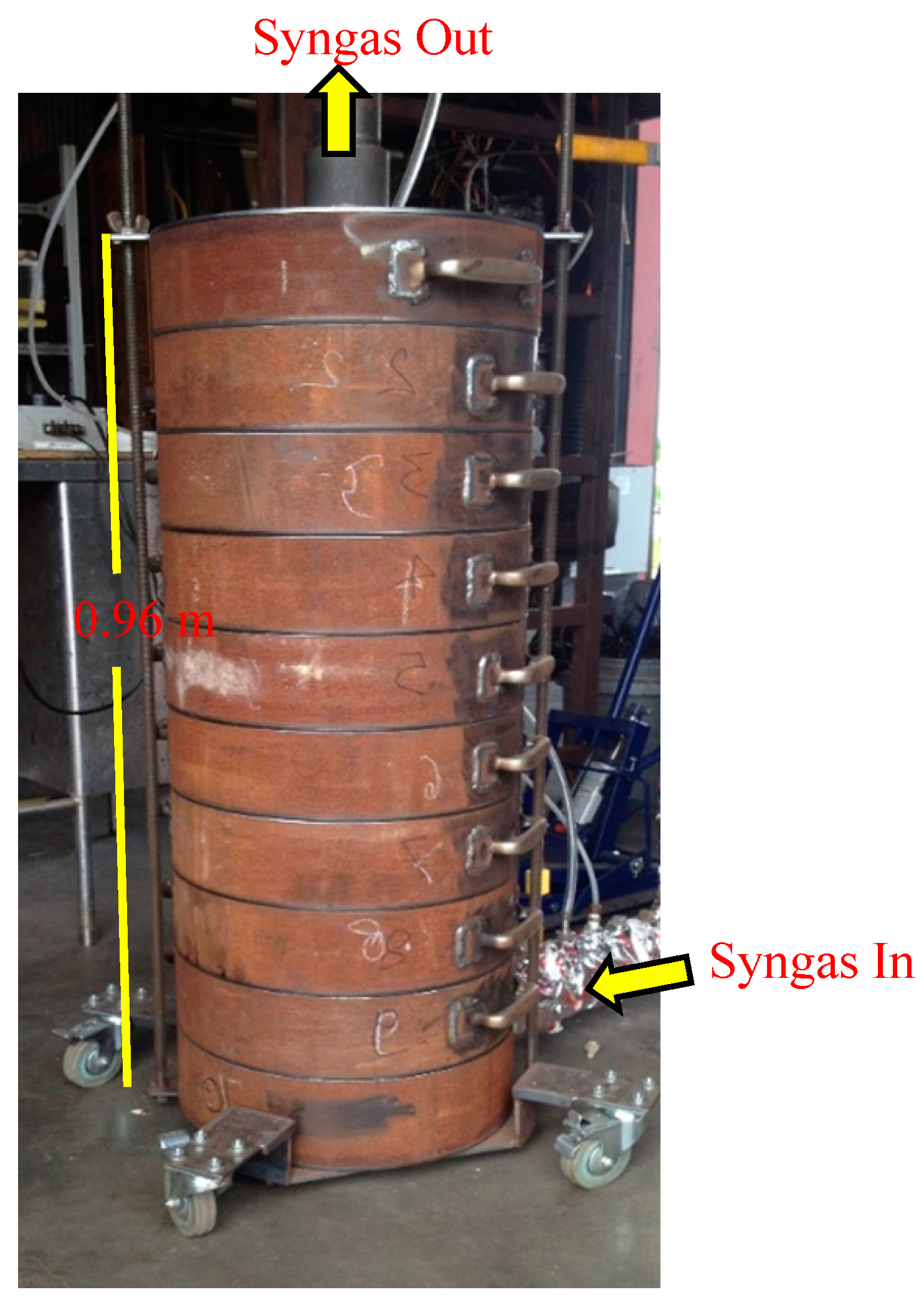
2.1. Experimental Set Up

Schematic diagrams of the experimental set up are shown in Figure 1 and Figure 2. Oklahoma State University patented downdraft gasifier (20 kW) [30] with an average feedstock consumption rate of 15 kg/h was operated at a low equivalence ratio (0.20) to generate syngas with high tar content. Operational conditions of gasifiers for each treatment are presented in Table 2. Switchgrass used as gasification feedstock was grown at the Agronomy Research Station of Oklahoma State University (Stillwater, OK, USA). A 10-layered cylindrical biomass filter system with total surface area of 1.26 m2 (bed height of 0.96 m and diameter of 0.17 m) was designed. Syngas entered into the filter at the bottom at a flow rate of 35 Nm3/h. Syngas exited through the filter top (Figure 3). Micro data acquisition (DAQ) K-type thermocouples (Omega Engineering, Norwalk, CT, US.) were installed to measure the gas temperature at the inlet and outlet of the filter system. The pressure drop across the filter system was measured using U-tube manometers (Dwywe Inc, Wilmington. NC, US).
The wood shavings, screened through 2 mm wire mesh, with a particle size between 2 mm and 1.5 cm were used as filter medium (Figure 4). Wood shavings were purchased from a local sawmill in Stillwater. A total of 4.0 kg of wood shavings was used for each run to maintain the uniform packed bed density of the filter. Syngas was passed through the filter for 1.0 h after the gasifier was at equilibrium condition. Chilled water (5 °C, flow rate of 15 L/min) for single tube heat exchanger (1.19 m height and 0.02 m diameter; Figure 5) was supplied by a water chiller (Model 30070, Schreiber Engineering Corporation, Cerritos, CA, USA). The oil bubbler (0.48 m height, 0.38 m diameter and 10 mm bubble size with 1-inch oil level; Figure 6) used canola oil that was supplied by Jedwards International, Inc. (Quincy, MA, USA). The oil bubbler was also cooled with chilled water (5 °C, flow rate of 15 L/min). The inlet and outlet syngas tar contents, pressure drop across the filter, temperatures at inlet and outlet of the filter, heating values of syngas and gas temperatures at inlet and outlet of the heat exchanger were recorded.

2.2. Tar and Syngas Sampling and Analysis

The tar removal efficiency of the filter was determined by comparing tar content at inlet and outlet of the filter. Tar sampling protocol by Good et al. [31] was used. The method consists of a series of six impingement bottles in which the syngas was passed. The first one served as a moisture collector. The gas then flowed through a series of four impinger bottles filled with a solvent, i.e., acetone to dissolve the tars. The last bottle was kept empty to ensure the collection of final condensates. For tar analysis, syngas was sampled at the inlet of cleaning system approximately 30 min after the gasifier reached equilibrium condition. The gas at the filter outlet was sampled 30 min after start of filter operation. During each test, syngas was separately sampled every 20 min at the filter outlet for analysis of gas composition using a gas chromatographer (Model CP-3800, Varian, Inc., Palo Alto, CA, USA). The tar content in syngas was calculated as the ratio of the weight of tar in sampled gas (g) and volume of sampled gas (m3).

3. Results and Discussion

Treatments were designed to investigate tar reduction (removal) efficiencies of wood shavings filter (dry filter) with and without syngas cooling and bubbling systems. Accordingly, the tar contents were measured at the inlet and outlet of the cleaning systems for the three treatments: (i) wood shavings filter; (ii) wood shavings filter after a heat exchanger; and (iii) wood shavings filter after an oil bubbler. Pressure drop, an important indicator in determining the tar absorbed by filter medium, was measured across the wood shavings filter over time. Similarly, because the temperature of syngas plays a vital role in condensation and deposition of tar, temperatures were recorded at the inlet and outlet of the cleaning systems. The gasifier was purposefully operated at low temperatures, which resulted in high syngas tar content to test the capabilities of the cleaning systems. The removal of tar can involve condensation or absorption process. In this experiment, the removal of tar by wood shavings involves condensation. Whereas, the removal of tar by oil is an absorption-based process because the solvent (oil) dissolves the tar products.

3.1. Tar Reduction Efficiencies

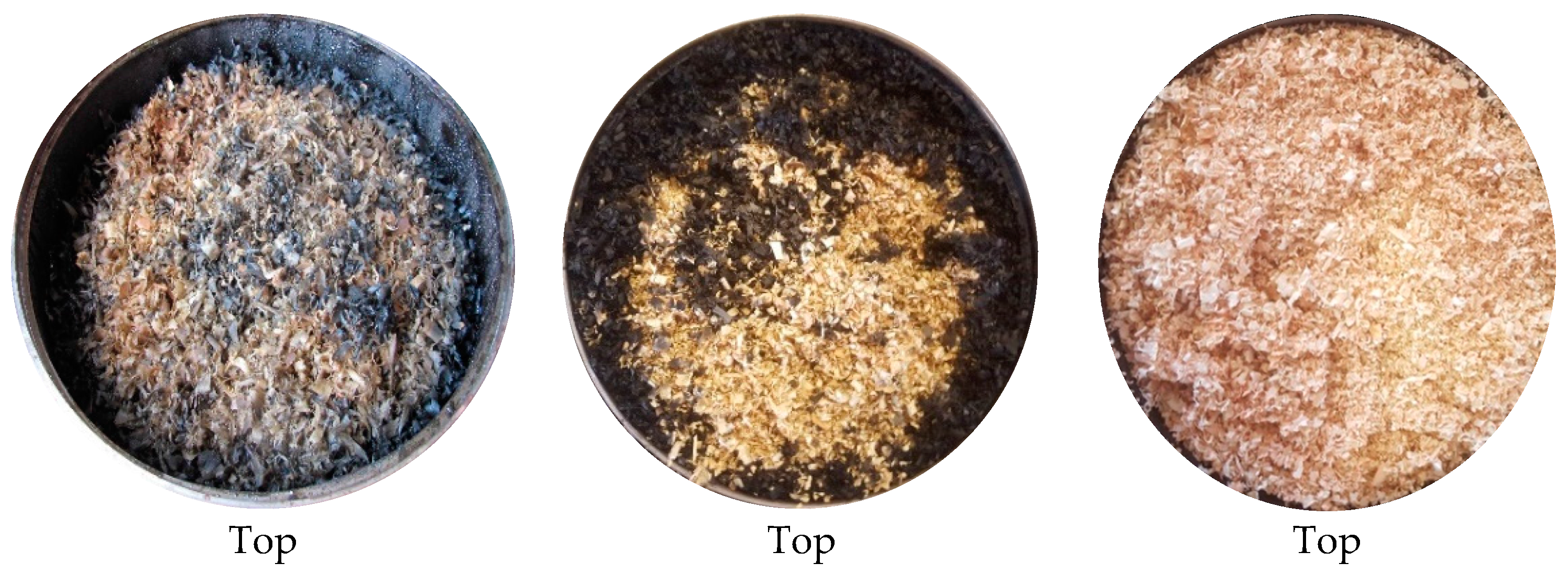
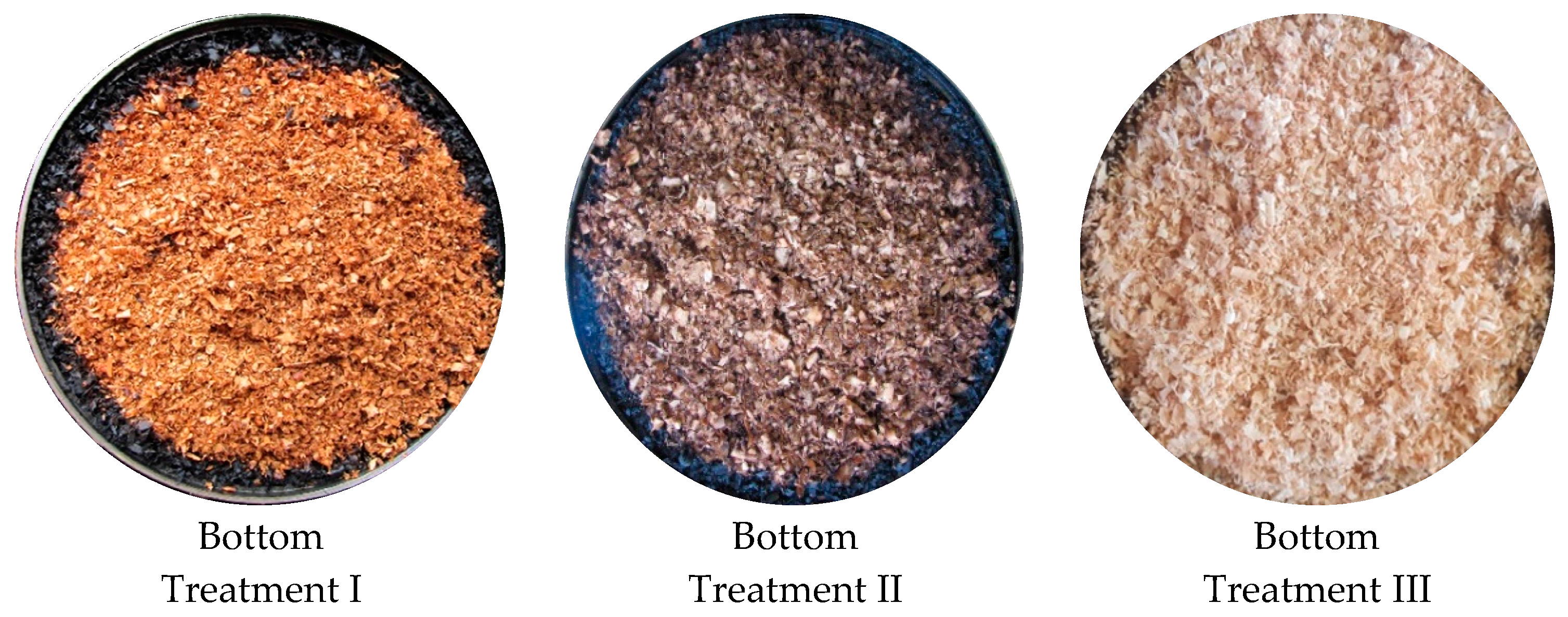
3.1.1. Tar Reduction Efficiency of Wood Shavings Filter (Treatment I)

Tar content at the inlet and outlet of wood shavings filter were 78 g/Nm3 and 70 g/Nm3, respectively (Table 3). A study [18] using corn cobs as the filter medium reported outlet tar content of 2 g/Nm3. The lower outlet tar content using corn cobs may be attributed to the two layers of sponges used in combination with the corn cobs. The tar removal efficiency of the wood shavings filter obtained in this study (10%) was much lower compared to 97% reported using a water scrubber and coconut coir filter [17] and 94% using spray towers and wood shavings filter [19]. Observation of biomass filter layers (Treatment I in Figure 7) revealed that more tar was adsorbed at the upper section and around the periphery of the filter. This was attributed to the lower temperatures near the periphery of the filter.

3.1.2. Tar Reduction Efficiency of Wood Shavings Filter in Combination with Heat Exchanger (Treatment II)

The inlet and outlet syngas tar contents of the filter system equipped with a wood shavings filter and heat exchanger, were 70 g/Nm3 and 27 g/Nm3, respectively, resulting in tar removal efficiency of 61% (Table 3). Unlike previous studies [15,17,19] that used direct (contact) cooling systems, such as spray towers and water scrubbers; the heat exchanger used in this study was an indirect (no contact) cooling system. Compared to Treatment I (only wood shavings filter), indirect cooling of syngas using a heat exchanger (Treatment II), reduced the dew point of tar and significantly improved tar removal efficiency. Figure 7 presents the pictorial comparison of tar adsorbed at top and bottom sections of the wood shavings filter. Similar to the observation made in Treatment I, more tar deposited at the top section and around periphery of the filter in Treatment II. Figure 7 also shows that the addition of the heat exchanger clearly aided in deposition of more tar on the wood shavings filter. However, the final tar content (27 g/Nm3) obtained in this treatment was higher than those obtained with dry filter used with direct (touch) syngas cooling and cleaning systems, such as sand bed filter with water spray towers (1.5 g/Nm3 final tar content) [15] and coconut coir filter with water scrubber (1.4 g/Nm3 final tar content) [17]. Similarly, the final tar content of this treatment is high than those of cleaning systems with a heat exchanger with bag house filter (35 mg/Nm3) [21]; and heat exchanger with venture scrubber (10 mg/Nm3) [22]. High outlet tar content in this study can be attributed to two primary reasons: (i) indirect cooling, used in this study, has low tar removal effectiveness; and (ii) inlet tar content was high (70 g/Nm3 vs. <10 g/Nm3) [15,19]. The result from Treatment II is comparable to the tar removal efficiency (61%) of the system with a cyclone, heat exchanger and oil bath filter [32]. These result, shows that indirect cooling of syngas with the heat exchanger increased the tar removal efficiency of the dry filter but further cleaning is still required if the syngas is used in an Internal Combustion (IC) engine. However, since water and some tar are condensed in the heat exchanger, the design of the heat exchanger must allow water and tars to flow out of the heat exchanger pipes. Use of a single vertical tube allowed us to collect water and tar condensed during the test. Tar deposition along the inner surface of the heat exchanger was minimal but after several runs, the inner surface required cleaning.

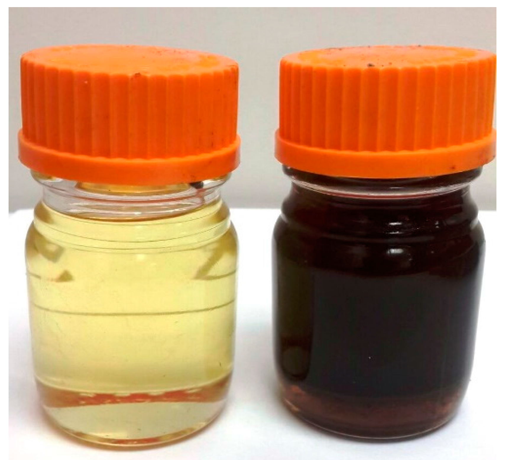
3.1.3. Tar Reduction Efficiency of Wood Shavings Filter with Vegetable Oil Bubbler (Treatment III)

To investigate the tar removal efficiency of wood shavings filter equipped with vegetable oil bubbler as cooling unit, the cleaning system was installed as specified in Figure 1 (Treatment III). Tar content at the inlet and outlet of the cleaning system were observed as 70 g/Nm3 and 1.9 g/Nm3, respectively (Table 3). The tar content at inlet of wood shavings filter (after oil bubbler) was 3.8 g/Nm3, which suggests that a large portion of the tar was condensed in oil bubbler (as shown in Figure 8), and is also evident from Figure 4, which shows that very little tar was condensed on the wood shavings filter.
High tar removal efficiency of the cleaning system equipped with oil bubbler (97%) indicates that, unlike in previous studies [24,25,27] that have used oil scrubber, an oil bubbler is also effective for removal of syngas tar. High tar removal efficiency of 98% with sunflower oil [24] and final tar content of 0.022 g/Nm3 with waste palm cooking oil [27] have been reported. The high tar removal efficiency of the oil-based cleaning system is attributed to oil’s lipophilicity characteristics, the ability of the oil to dissolve non-polar hydrocarbons [27]. Tar compounds are lipophilic in nature and can mix well with vegetable oils as these oils have saturated and unsaturated fatty acids.
Feasibility of removing syngas tar with biomass and oil is promising because the tar mixed oil and wood shavings can be reused in gasifier reactors as feedstock, eliminating the need to treat waste effluent. For example, the scrubbing oil was reused and tars were recycled into the gasifier by the Energy Research Center of the Netherlands [28]. Oil used in removing tar was put in the regeneration process using filtration and centrifugal sedimentation techniques and reused in the scrubber [29]. Wood shavings also removed syngas moisture depicted by the high moisture content of the filter after the test. However, the tar content at the outlet of oil bubbler was still not low enough for engine application. In conclusion, oil may have been effective in reduction of heavy tar [24], but additional cleaning is necessary for the removal of light tars.

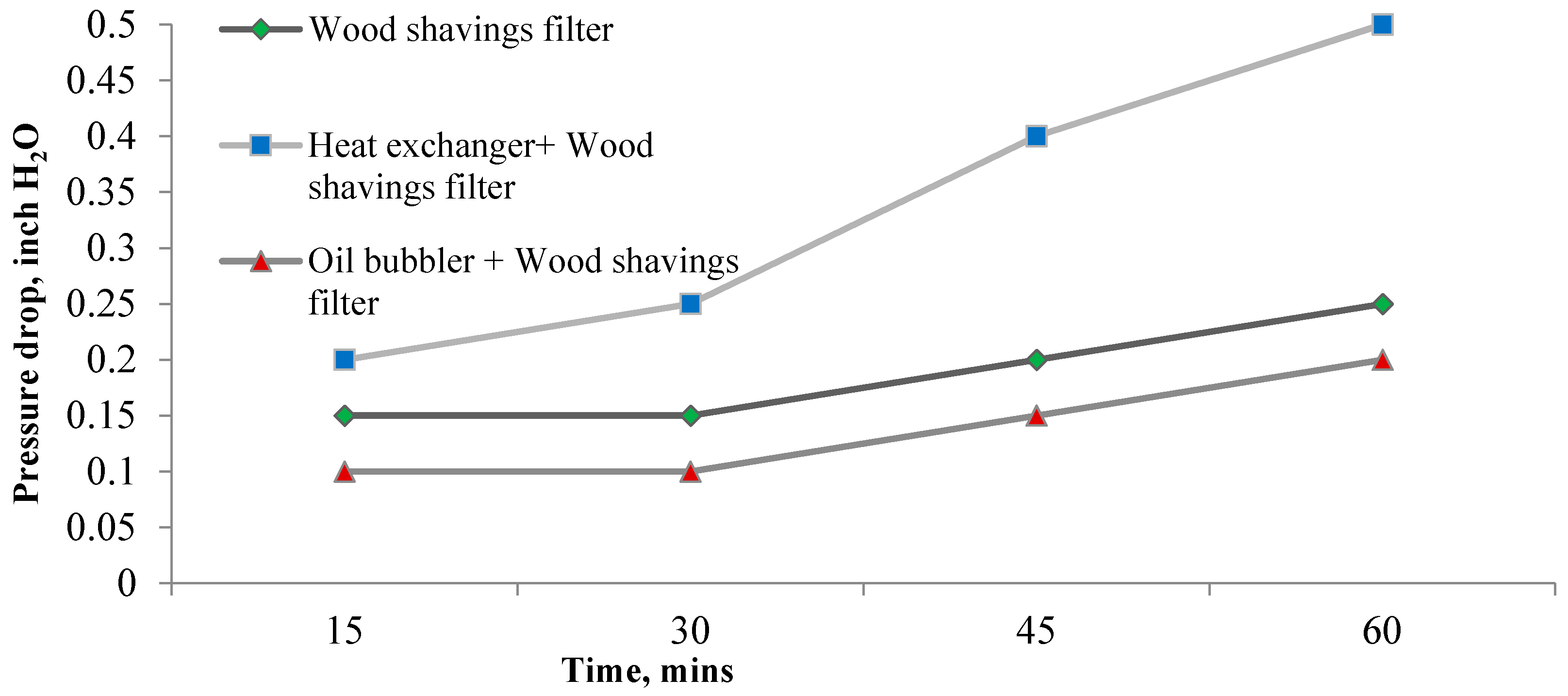
3.2. Variation of Pressure Drop across Wood Shavings Filter for the Three Treatments

Pressure drop across the wood shavings filter depends on amount of tar accumulated in the filter medium. As shown in Figure 9, pressure drop across the filter increased with time due to continued accumulation of tar on the filter medium for all three treatments. However, throughout the test duration, pressure drop was the highest for Treatment II (when heat exchanger was used before the filter) and the lowest for Treatment III (when oil bubbler was used before the filter). The trend of pressure drop indicated that tar deposition on the filter was the highest for Treatment II and the lowest for Treatment III. However, overall tar removal efficiency was the highest for Treatment III (97%) and the lowest for Treatment I (10%). These observations indicated that the highest tar removal for Treatment III is due to the oil bubbler, which removed most of the tars leaving only a small quantity of tar deposited on the filter hence the pressure drop across the filter was minimal. Syngas tar content measured at the outlet of the oil bubbler (3.8 g/Nm3) confirmed the finding that only a small quantity of tar (3.8 g/Nm3) was removed by the filter medium and most of the tar was removed by the oil bubbler (66.2 g/Nm3). For Treatment I, as the filter medium was not augmented with any other cleaning method, the pressure drop increased with increasing tar accumulation on the filter over time. In Treatment II, use of a heat exchanger before the filter medium reduced the temperature of syngas entering into the filter medium from 135 °C to 71 °C, which led to increased condensation of the tar on the filter medium. Tar deposition observed on the heat exchanger was minimal, indicating that most of the tar was removed by the filter. Higher pressure drop across the filter for Treatment II as compared to Treatment I also indicated that tar deposition on the filter for Treatment II (with heat exchanger) was higher than that for Treatment I (only filter). Hence, the use of heat exchanger reduced the syngas temperature and increased tar deposition on the filter medium. The pressure drops across the filter for all three treatments (0.2–0.5 in of H2O) were lower compared to those reported by others (0.5–2 in of H2O) [15,17] due to low condensation of tar by wood shavings. This low pressure drop is beneficial for power generation application because pressure available at the engine manifold is high and prevents high back pressure in the gasifier.

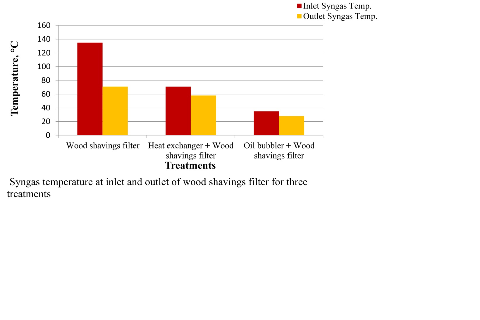
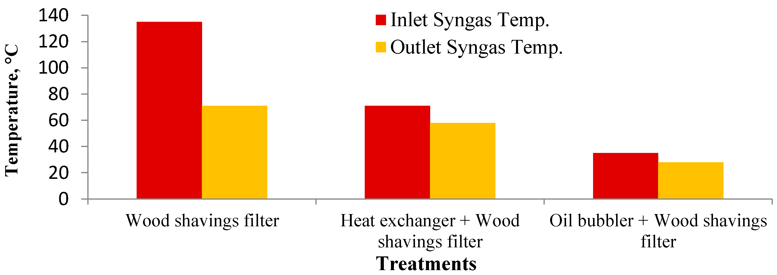
3.3. Variation of Gas Temperature at Inlet and Outlet of Wood Shavings Filter for Three Treatments

Temperature of syngas is a key parameter affecting condensation of tar. Figure 10 shows the 1 h average syngas temperature at the inlet and outlet of the wood shavings filter for the three treatments. The filter inlet temperature for Treatment I was the highest, followed by Treatment II and Treatment III. The trend shows that the cooling by the heat exchanger and the oil bubbler were effective. The syngas temperature entering into the cleaning system was the same (about 135 °C) for all three treatments; however, because of the use of heat exchanger and oil bubbler before the filter, the syngas temperature at the filter inlet was different. The average syngas temperature entering into the cleaning system was low (about 135 °C), due to the use of long piping between the cyclone and cleaning system. As a result, tar condensation could have happened along the piping. The difference between inlet and outlet syngas temperatures of the filter (Figure 10) was the highest for Treatment I, followed by Treatments II and III. This trend can be attributed to the effectiveness of heat exchanger and oil bubbler in reducing gas temperature at the filter inlet.
As expected, low syngas temperatures at the filter led to high condensation on the wood shavings medium. In addition, low temperature of 30 °C is desired for feeding into IC engine, [10]. The oil bubbler (Treatment III) was effective in reducing syngas temperature at the filter outlet to 27 °C. The heat exchanger-based cooling system also reduced the syngas temperature; however, the outlet syngas temperature (58 °C) was still higher than desired for most engine applications. Using a heat exchanger with multiple tubes may further reduce the temperature sufficient for engine applications.

3.4. Heating Value of Syngas

Heating value of syngas affects performance of the downstream power generation unit [21]. The lower heating values (LHVs) of syngas sampled at the outlet of the wood shavings filter for the three treatments were in the range of 5–6 MJ·Nm−3. These results are comparable to 5.3 MJ·Nm−3 produced from a downdraft gasifier with olive kernel as feedstock and wet scrubber and heat exchanger as a cleaning unit [22] and 5.79 MJ·Nm−3 produced from an 18 kW gasifier using hardwood chips as feedstock [33]. The average gas composition for each of the three treatments are presented in Table 4. The variation in heating values of product gas can be attributed to the difference in composition of combustible gases, such as H2, CO and CH4.

4. Conclusions

The performance of three types of syngas cleaning systems using wood shavings as the filter medium was evaluated. Tar removal efficiencies of the three treatments were: wood shavings filter (10.28%) < wood shavings filter with heat exchanger (60.30%) < wood shavings filter with oil bubbler (97%). Even though the heat exchanger reduced the syngas temperature and led to increased condensation of tars, the vegetable oil bubbler was more effective in the removal of tars because of the oil’s ability to absorb tar. Tar deposited at the top and around the periphery of the wood shavings filter was the highest when the heat exchanger was used.

Acknowledgements

The authors would like to acknowledge Oklahoma State University Research Foundation and Oklahoma Agricultural Experiment Station for their support.

Author Contributions

All authors significantly contributed to the scientific study and writing. Thapa performed tests and collected data, whereas, Bhoi, Kumar and Huhnke supervised the project, and all authors contributed to writing the manuscript.

Conflicts of Interest

The authors declare no conflict of interest.

References

  1. Srirangan, K.; Akawi, L.; Moo-Young, M.; Chou, C.P. Towards sustainable production of clean energy carriers from biomass resources. Appl. Energy 2012, 100, 172–186. [Google Scholar] [CrossRef]
  2. Devi, L.; Ptasinski, K.J.; Janssen, F.J. A review of the primary measures for tar elimination in biomass gasification processes. Biomass Bioenergy 2003, 24, 125–140. [Google Scholar] [CrossRef]
  3. Heidenreich, S.; Foscolo, P.U. New concepts in biomass gasification. Prog. Energy Combust. Sci. 2015, 46, 72–95. [Google Scholar] [CrossRef]
  4. Molino, A.; Chainese, S.; Musmarra, D. Biomass gasification technology: The state of the art overview. J. Energy Chem. 2016, 25, 10–25. [Google Scholar] [CrossRef]
  5. Anis, S.; Zainal, Z.A. Tar reduction in biomass producer gas via mechanical, catalytic and thermal methods: A review. Renew. Sustain. Energy Rev. 2011, 15, 2355–2377. [Google Scholar] [CrossRef]
  6. Advantages and Efficiency of Gasification. Available online: https://www.netl.doe.gov/research/coal/energy-systems/gasification/gasifipedia/clean-power (accessed on 31 January 2017).
  7. Ahmad, A.A.; Zawawi, N.A.; Kasim, F.H.; Inayat, A.; Khasri, A. Assessing the gasification performance of biomass: A review on biomass gasification process conditions, optimization and economic evaluation. Renew. Sustain. Energy Rev. 2016, 53, 1333–1347. [Google Scholar] [CrossRef]
  8. Huang, J.; Schmidt, K.G.; Bian, Z. Removal and conversion of tar in syngas from woody biomas gasification for power utilization using catalytic hydrocracking. Energies 2011, 4, 1163–1177. [Google Scholar] [CrossRef]
  9. Asadullah, M. Biomass gasification gas cleaning for downstream applications: A comparative critical review. Renew. Sustain. Energy Rev. 2014, 40, 118–132. [Google Scholar] [CrossRef]
  10. Baratieri, M.; Baggio, P.; Bosio, B.; Grigiante, M.; Longo, G.A. The use of biomass syngas in IC engines and CCGT plants: A comparative analysis. Appl. Therm. Eng. 2009, 29, 3309–3318. [Google Scholar] [CrossRef]
  11. Singh, R.N.; Mandovra, S.; Balwanshi, J. Performance of evaluation of “jacketed cyclone” for reduction of tar from producer gas. Int. Agric. Eng. J. 2013, 22, 1–5. [Google Scholar]
  12. Hasler, P.; Nussbaumer, T. Gas cleaning for IC engine applications from fixed bed biomass gasification. Biomass Bioenergy 1999, 16, 385–395. [Google Scholar] [CrossRef]
  13. Chainese, S.; Loipersbock, J.; Malits, M.; Rauch, R.; Hofbauer, H.; Molino, A.; Musmarra, D. Hydrogen from the high temperature water gas shift reaction with an industrial Fe/Cr catalyst using biomass gasification tar rich synthesis gas. Fuel Process. Technol. 2015, 132, 39–48. [Google Scholar] [CrossRef]
  14. Chainese, S.; Fail, S.; Binder, M.; Rauch, R.; Hofbauer, H.; Molino, A.; Blasi, A.; Musmarra, D. Experimental investigations of hydrogen production from CO catalytic conversion of tar rich syngas by biomass gasification. Catal. Today 2016, 277, 182–191. [Google Scholar] [CrossRef]
  15. Pathak, B.S.; Kapatel, D.; Bhoi, P.R.; Sharma, A.M.; Vyas, D.K. Design and development of sand bed filter for upgrading producer gas to IC engine quality fuel. Int. Energy J. 2007, 8, 15–20. [Google Scholar]
  16. Nakamura, S.; Unyaphan, S.; Yoshikawa, K.; Kitano, S.; Kimura, S.; Shimizu, H.; Tiara, K. Tar removal performance of bio-oil scrubber for biomass gasification. Biofuels 2014, 5, 597–606. [Google Scholar] [CrossRef]
  17. Rameshkumar, R.; Mayilsamy, K. A novel compact bio-filter system for a downdraft gasifier: An experimental study. AASRI Procedia 2012, 3, 700–706. [Google Scholar] [CrossRef]
  18. Allesina, G.; Pedrazzi, S.; Montermini, L.; Giorgini, L.; Bortolani, G.; Tartarin, P. Porous filtering media comparison through wet and dry sampling of fixed bed gasification. J. Phys. Conf. Series 2014, 547. [Google Scholar] [CrossRef]
  19. Pareek, D.; Joshi, A.; Narnaware, S.; Verma, V.K. Operational experience of agro-residue briquettes based power generation system of 100 kW capacity. Int. J. Renew. Energy Res. 2012, 2, 477–485. [Google Scholar]
  20. Henriken, U.; Ahrenfeldt, J.; Jensen, T.K.; Gobel, B.; Bentzen, J.D.; Hindsgaul, C.; Sorensen, L.H. The design, construction and operation of a 75 kW two-stage gasifier. Energy 2006, 31, 1542–1553. [Google Scholar] [CrossRef]
  21. Raman, P.; Ram, N.K.; Gupta, R. A dual fired downdraft gasifier system to produce cleaner gas for power generation: Design, development and performance analysis. Energy 2013, 54, 302–314. [Google Scholar] [CrossRef]
  22. Margaritis, N.K.; Grammelis, P.; Vera, D.; Jurado, F. Assessment of operational results of a downdraft biomass gasifier coupled with a gas engine. Proc. Soc. Behav. Sci. 2012, 48, 857–867. [Google Scholar] [CrossRef]
  23. Phuphukrat, T.; Namioka, T.; Yoshikawa, K. Absorptive removal of biomass tar using water and oily materials. Bioresour. Technol. 2011, 102, 543–549. [Google Scholar] [CrossRef]
  24. Paethanom, A.; Bartocci, P.; Alessandro, B.D.; Amico, M.D.; Testarmata, F.; Moriconi, N.; Slopiecka, K.; Yoshikawa, K.; Fantozzi, F. A low-cost pyrogas cleaning system for power generation: Scaling up from lab to pilot. Appl. Energy 2013, 111, 1080–1088. [Google Scholar] [CrossRef]
  25. Bhoi, P.R.; Huhnke, R.L.; Kumar, A.; Payton, M.E.; Patil, K.N.; Whiteley, J.R. Vegetable oil as a solvent for removing producer gas tar compounds. Fuel Proc. Technol. 2015, 133, 97–104. [Google Scholar] [CrossRef]
  26. Nakamura, S.; Siriwat, U.; Yoshikawa, K.; Kitano, S. Development of tar removal technologies for biomass gasification using the byproducts. Energy Procedia 2015, 75, 208–213. [Google Scholar] [CrossRef]
  27. Ahmad, N.A.; Zainal, Z.A. Performance and chemical composition of waste palm cooking oil as scrubbing medium for tar removal from biomass producer gas. J. Natural Gas Sci. Eng. 2016, 31, 256–261. [Google Scholar] [CrossRef]
  28. MILENA and OLGA Get together for High Efficiency and Low Tar. Available online: http://www.modernpowersystems.com/features/featuremilena-and-olga-get-together-for-high-efficiency-and-low-tar-4815584/ (accessed on 12 December 2016).
  29. Tarnpradab, T.; Unyaphan, S.; Takahasi, F.; Yoshikawa, K. Improvement of the biomass tar removal capacity of scrubbing oil regenerated by mechanical soild-liquid separation. Energy Fuels 2017, 31, 1564–1573. [Google Scholar] [CrossRef]
  30. Patil, K.N.; Huhnke, R.L.; Bellmer, D. Downdraft Gasifier with Internal Cyclonic Combustion Chamber. U.S. Patent 8,657,892 B, 25 February 2014. [Google Scholar]
  31. Good, J.; Ventress, L.; Knoef, H.; Zielke, U.; Hansen, P.L.; Kamp, W.V.D.; Wild, P.D.; Coda, B.; Paasen, S.V.; Kiel, J. Sampling and Analysis of Tar and Particles in Biomass Producer Gases; European Committee for Standardization (CEN): Brussels, Belgium, 2005. [Google Scholar]
  32. Atnaw, S.M.; Kueh, S.C.; Sulaiman, S.A. Study on tar generated from downdraft gasification of oil palm fronds. Sci. World J. 2014. [Google Scholar] [CrossRef] [PubMed]
  33. Shah, A.; Srinivasan, R.; To, S.D.; Columbus, E.P. Performance and emissions of a spark-ignited engine driven generator on biomass based syngas. Bioresour. Technol. 2010, 101, 4656–4661. [Google Scholar] [CrossRef] [PubMed]
Figure 1. Schematic diagram of the three gas cleaning treatments: (I) wood shavings filter; (II) heat exchanger + wood shavings filter; and (III) oil bubbler + wood shavings filter.
Energies 10 00349 g001
Figure 2. Wood shavings filter column installed with a gasifier system at Oklahoma State University.
Energies 10 00349 g002
Figure 3. 10-layered biomass-based filter system.
Energies 10 00349 g003
Figure 4. Wood shavings used as the filter medium for all treatments.
Energies 10 00349 g004
Figure 5. A single tube heat exchanger used for cooling syngas for treatment II.
Energies 10 00349 g005
Figure 6. Oil bubbler unit for treatment III.
Energies 10 00349 g006
Figure 7. Top and bottom sections of the filter for three treatments: (I) wood shavings filter; (II) heat exchanger + wood shavings filter; and (III) oil bubbler + wood shavings filter.
Energies 10 00349 g007aEnergies 10 00349 g007b
Figure 8. Canola oil (used in oil bubbler for treatment III) before and after the test.
Energies 10 00349 g008
Figure 9. Variation of pressure drop of wood shavings filters over time.
Energies 10 00349 g009
Figure 10. Syngas temperature at the inlet and outlet of the wood shavings filter for the three treatments.
Energies 10 00349 g010
Table 1. Tar acceptance limit for different devices. IC: internal combustion.
End Use DeviceTar Acceptance Limit (g/Nm3)
Industrial gas turbine<0.005
Fuel cells<0.001
IC and diesel engines0.01–0.1
Compressors0.05–0.5
Table 2. Gasifier operating conditions.
ParametersTreatment ITreatment IITreatment III
Fuel feed rate, kg/h16.51616.5
Combustion zone temperature, °C719700703
Equivalence ratio0.200.200.20
Table 3. Tar contents of raw and cleaned syngas (dry basis) with the three tar cleaning treatments.
TreatmentRaw Gas Tar Concentration (g/Nm3)Cleaned Gas Tar Concentration (g/Nm3)
Wood shavings filter (I)7870
Heat exchanger + wood shavings filter (II)7027
Oil bubbler + wood shavings filter (III)701.9
Table 4. Syngas composition and heating value for the three cleaning treatments.
Gas componentsTreatment ITreatment IITreatment III
H2 (% v/v)10.212.711.5
N2 (% v/v)52.750.350.0
O2 (% v/v)2.62.01.5
CO (% v/v)12.814.014.6
CH4 (% v/v)2.92.94.8
CO2 (% v/v)15.614.219.1
LHV (MJ·Nm−3)5.4325.7665.680

