Energy Saving Potential of a Thermoelectric Heat Pump-Assisted Liquid Desiccant System in a Dedicated Outdoor Air System


1
New and Renewable Energy Research Division, Korea Institute of Energy Research, 152 Gajeong-Ro, Yuseong-Gu, Daejeon 34129, Korea
2
Department of Architectural Engineering, College of Engineering, Hanyang University, 222 Wangsimni-Ro, Seongdong-Gu, Seoul 04763, Korea
*
Author to whom correspondence should be addressed.
Energies 2017, 10(9), 1306; https://doi.org/10.3390/en10091306
Submission received: 2 July 2017
/
Revised: 22 August 2017
/
Accepted: 29 August 2017
/
Published: 1 September 2017
Abstract
:The main objective of this study was to develop a thermoelectric heat pump and liquid desiccant system based on a dedicated outdoor air system (THPLD-DOAS). An internally-cooled and -heated liquid desiccant system was used and a thermoelectric heat pump (THP) served as the desiccant cooling and heating energy source for dehumidification and regeneration of the desiccant solution, respectively. In order to investigate the energy-saving potential of the proposed system, its thermal performance and operating energy consumption during the cooling season were compared to those of a conventional dedicated outdoor air system with a ceiling radiant cooling panel system (DOAS-CRCP). Detailed simulations for each system were conducted under hot and humid climatic conditions. Their thermal performance under various room sensible heat factor (RSHF) conditions was evaluated to observe the energy performance, depending on the dehumidification performance, of the liquid desiccant system integrated with the THP. The results showed that the coefficient of performance (COP) of the THP ranged from 0.8 to 1.2 to maintain a sufficient dehumidification rate. The operating energy of the THPLD of the proposed system was 6.6% to 16.0% less than that of the chiller operating energy of a conventional DOAS. Consequently, the proposed system consumed 0.6–23.5% less operating energy compared to the conventional DOAS.
1. Introduction
Dedicated outdoor air systems with a ceiling radiant cooling panel (DOAS-CRCP) have been thoroughly investigated over the past few decades and are widely applied to a broad range of buildings [1,2,3,4,5]. The DOAS-CRCP ensures the decoupling of sensible and latent cooling functions in the air conditioning process and in the distribution of required ventilation for spaces. The DOAS meets the ventilation and latent cooling demands, while the CRCP is responsible for sensible cooling. Independent control of temperature and humidity, and proper ventilation in the DOAS-CRCP operation can enhance the indoor environmental quality and obtain operating energy savings compared to conventional air conditioning (AC) systems [6,7].
Recently, in order to enhance the humidity control and energy saving performance of the DOAS, a liquid desiccant-assisted DOAS has been proposed [8,9,10,11]. Liquid desiccant systems are attracting particular interest as an alternative dehumidification technology to conventional vapor compression systems [12,13]. In the liquid desiccant unit, the strong desiccant solution entering the absorber should be cooled to enhance its dehumidification performance, and the weak solution entering the regenerator should be heated for regeneration. It is possible to consider a free cooling and renewable heat source for liquid desiccant system operation in an energy-conservative manner [13,14,15]. A heat pump simultaneously providing cooling and heating to the desiccant solution can also be considered for the liquid desiccant system [16,17,18].
Ge et al. [8,11] investigated a liquid desiccant-assisted DOAS. They indicated that their system saved 19.4% of the total energy consumption by employing an optimum control strategy. Liu et al. [9] proposed a combination of a liquid desiccant system and indoor terminal devices such as a fan coil unit or radiant ceiling panel for independent control of temperature and humidity. They demonstrated that the proposed system reduced the primary energy consumption and operating cost. Xiao et al. [10] proposed a novel DOAS adopting a liquid desiccant system and a total heat recovery. They showed that their system improved the system COP in the range of 19.9–34.8%.
On the other hand, a thermoelectric heat pump (THP) is also attracting considerable interest as an alternative to the conventional vapor compression heat pump system. The THP does not have moving parts, such as the refrigerant and compressor used in the conventional heat pump. Some studies have been conducted to adapt the THP to a building air conditioning system [19,20,21,22,23,24,25].
Liu et al. [19] proposed the use of a thermoelectric cooler and heater as a heat pump. Chen et al. [20] investigated the thermodynamic behavior of a two-stage THP, and derived a model of the returned heating load function of the working current and coefficient of performance. Riffat et al. [21] compared a mathematical model and the test results of a small THP prototype system, and then proposed correction factors to improve the prediction accuracy.
Lai et al. [22] established a new cycle model of a two-stage combined THP system. They suggested that two-stage THP systems have to be used over a large temperature range of the heated space and heat sink. Khire et al. [23] proposed a multi-objective optimization-based design strategy for the thermoelectric unit of active building envelope systems. Kim et al. [24] proposed an optimal design of an air-to-air THP for building ventilation and found that the coefficient of performance (COP) of the proposed system was enhanced by 4%. Han et al. [25] investigated a thermoelectric ventilator and found that the maximum COPs were 4.78 and 4.16 in summer and winter operations, respectively.
As for the liquid desiccant system integrated with a heat pump, Yadav [26] simulated the energy-saving potential of a vapor compression and liquid desiccant hybrid solar air conditioning system. Kinsara et al. [27,28] also proposed a hybrid air conditioning system using liquid desiccant, and conducted a parametric analysis to investigate the effects of key parameters on the performance of the proposed system. Ahmed et al. [29] suggested a hybrid vapor absorption and liquid desiccant system using a lithium bromide (LiBr) solution. Dai et al. [30] experimentally compared a vapor compression system with two hybrid systems; that is, a heat pump integrated with a liquid desiccant system, and a heat pump integrated with liquid desiccant and evaporative cooling systems. Ani et al. [31] fabricated and tested a hybrid system consisting of a vapor compression unit, liquid desiccant system, and flat solar hot water collector. Ma et al. [32] performed experimental research on a hybrid air conditioning system for a green building demonstration project in Shanghai. They demonstrated that the performance of their system could be compared to a conventional vapor compression system. Zhang et al. [33] evaluated the thermodynamic performance of a no-frost hybrid air conditioning system with liquid desiccant dehumidification in summer and winter operation modes. Bergero and Chiari [34] examined the performance of a hybrid air conditioning system. They indicated that a significant operating energy saving was achieved in their system compared to the traditional direct-expansion system during summer operation.
From the studies referenced above, it is evident that a hybrid heat pump system integrated with a liquid desiccant system can reduce the operating energy consumption compared to conventional vapor compression systems. Moreover, according to the Montreal protocol and its amendments [35,36], the usage of chlorofluorocarbons and hydro-chlorofluorocarbons should be restricted and prohibited. As a result, alternative heat pump systems for heating, ventilating, and air conditioning (HVAC) should be adopted in the building sector [36]. One of the feasible alternatives to the conventional vapor compression system without usage of chlorofluorocarbons and hydro-chlorofluorocarbons is the THP and liquid desiccant (LD) system. From the literature, the integration of the THP and LD systems has been scarcely investigated.
This research proposed a THP assisted liquid desiccant (THPLD) system, as an alternative to the conventional cooling coil, and an integration method of the THPLD into the DOAS was suggested. In order to estimate the feasibility of the proposed system, the operating energy saving potential of the proposed system over a conventional DOAS-CRCP system was evaluated by carrying out detailed energy simulations during the cooling season.
2. System Overview
2.1. A THP-Assisted Liquid Desiccant (THPLD) System
The LD system is composed of an absorber and a regenerator. When the process air is directly contacted with a sprayed desiccant solution in the absorber and regenerator, heat and moisture are transferred between them. In the absorber, when the partial vapor pressure of the desiccant solution is lower than that of the process air, the moisture in the process air is absorbed by the desiccant solution. Since the partial vapor pressure of the desiccant solution depends on the solution temperature, the solution should be cooled down to a temperature that has a lower vapor pressure than that of the process air. Adversely, in order to regenerate the desiccant solution in the regenerator, the solution should be heated to transfer the moisture from the desiccant solution to the regeneration air.
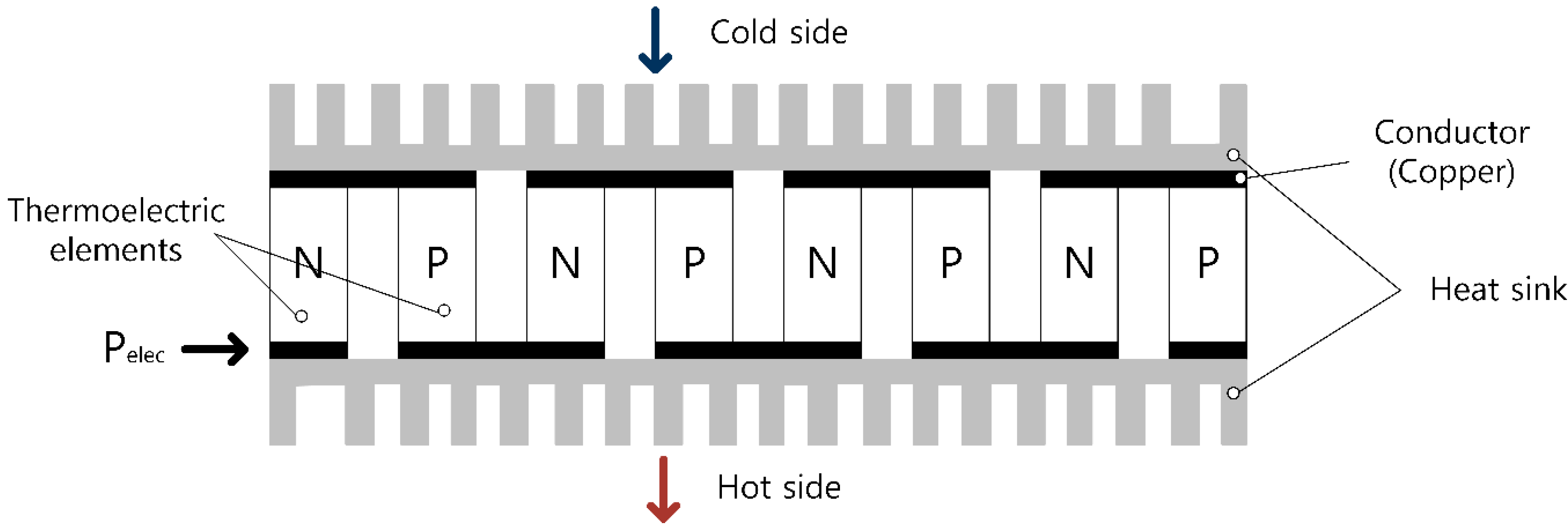
A thermoelectric module (TEM) is a small sized semiconductor that transfers heat from the cold side to the hot side, in a similar way to the conventional heat pump operation (Figure 1). A TEM is frozen-free and can provide rapid cooling and heating compared to the hydronic system. A TEM is powered by direct current, and heat is absorbed on the cold side of the TEM and dissipated to its hot side. The cooling and heating mode of the TEM can be modified by changing the direction of the current. The modulation of the working current controls the absorption or dissipation rate of the heat energy [37].
A TEM has economic benefits in relation to its initial cost, resulting in low installation and implementation costs compared to a conventional refrigerant. It does not require using a water pump or other accessories [38]. The THP is a system that uses TEMs and transfers the heat from the cold side to the hot side by attaching them onto heat sinks.
Figure 2 shows a schematic of the thermoelectric heat pump-assisted liquid desiccant system (THPLD), which consists of the following major components: the absorber, regenerator, and THP. The task of the absorber is to dehumidify the process air, and that of the regenerator is to regenerate the weak desiccant solution. The THP provides cooling to the desiccant solution in the absorber on the cold side, and heating to the solution in the regenerator on the hot side.
Internally-cooled and -heated types of liquid desiccant systems are used in the THPLD system to improve the thermal performance of the LD system. The desiccant solution is sprayed into the cold side of THP, and it absorbs moisture from the process air. The dissipated heat from the hot side of the THP heats the weak desiccant solution in the regenerator for regeneration of the desiccant solution.
2.2. THPLD-Based Dedicated Outdoor Air System (DOAS)
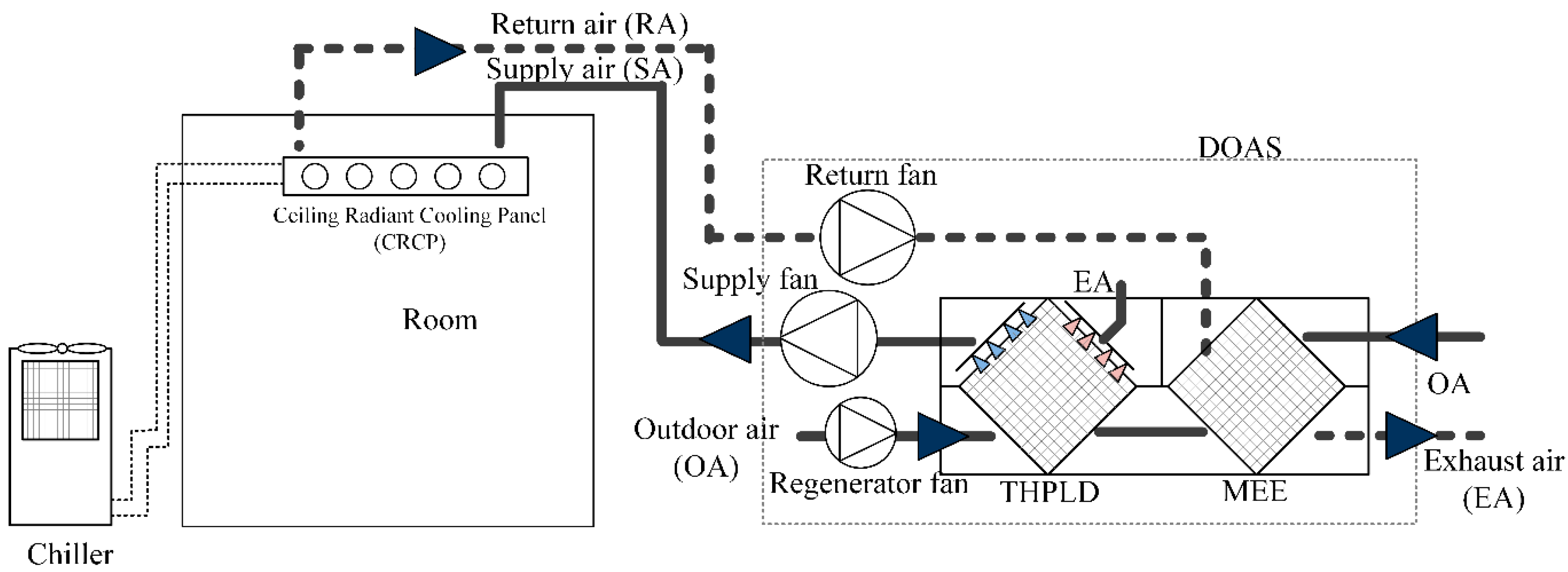
Figure 3 presents a schematic of the DOAS integrated with the THPLD. The DOAS accommodates ventilation demand, latent load, and some of the sensible cooling load of the space, while the CRCP meets the remaining sensible cooling demand. The supply airflow rate of the DOAS is usually the minimum required ventilation rate, while it can be varied if a demand-control ventilation strategy is applied [39].
The membrane enthalpy heat exchanger (MEE) is used in the proposed DOAS to pre-cool and pre-dehumidify the introduced outdoor air (OA) by heat and moisture exchange with the return air in the cooling season operation. In the conventional DOAS, the target supply air (SA) condition is met by the cooling coil, and a reheat system may be required to increase the SA temperature up to a neutral temperature [40].
On the other hand, by integrating the liquid desiccant system in the DOAS [8,9,10,11], one can expect an improvement in the indoor humidity control and operating energy savings compared to traditional air conditioning systems or a conventional DOAS.
As shown in Figure 3, the THPLD-assisted DOAS consists of an enthalpy heat exchanger, THPLD, and CRCP. In the proposed system, the THPLD dehumidifies the process air that is preconditioned by the enthalpy heat exchanger, and then supplies the dehumidified air at the neutral temperature. The CRCP removes the sensible cooling load of the space.
3. Research Methodology
3.1. Building Information
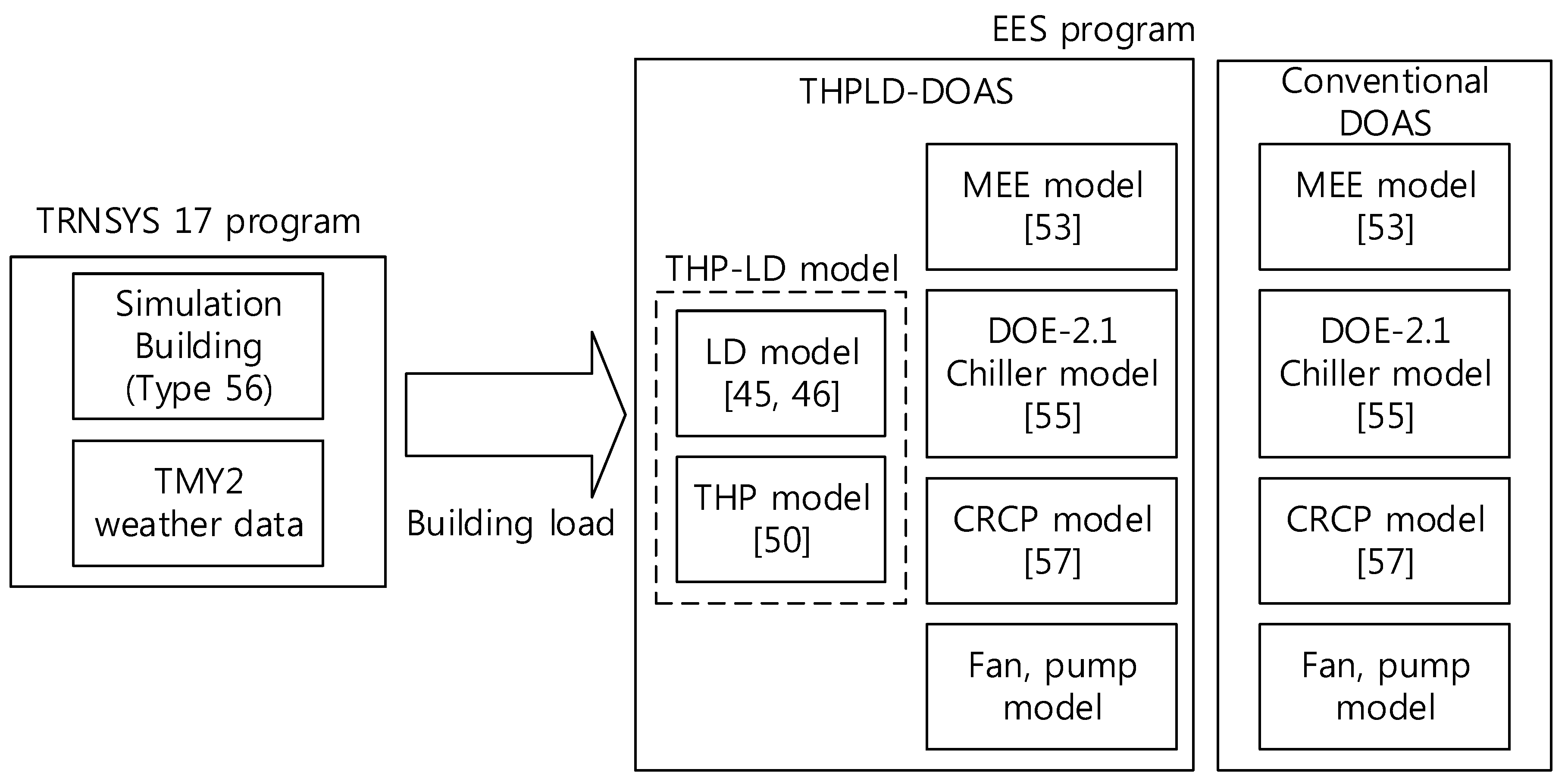
Figure 4 shows the overview of the simulation process of this research. In order to estimate the operating energy consumption of a DOAS integrated with the THPLD, a model building was defined and its cooling load was initially estimated using a TRaNsient Systems Simulation (TRNSYS) 17 [41] program. Then, the operating energy consumption of the proposed DOAS and conventional DOAS was estimated using the Engineering Equation Solver (EES) program [42], which is a commercial equation solver program. Table 1 shows the physical information of the model building. The multizone building modeling with Type 56 and TRNBuild on the TRNSYS 17 was conducted in this research.
To observe the operating energy consumption in the cooling season, the proposed and conventional systems serving the model building were simulated in June, July, and August, representing the hot and humid OA condition.
The room sensible heat factor (RSHF) is the ratio of sensible cooling load to total cooling load (Equation (1)) [43]. The total cooling load is composed of the sensible and latent cooling loads. In order to cover the various types of buildings in terms of latent load characteristics, the RSHF was set in the range of 0.97 to 0.7. The model building’s sensible cooling load was set to 4.5 kW, and the latent load varied depending on the RSHF.
3.2. System Simulation Overview
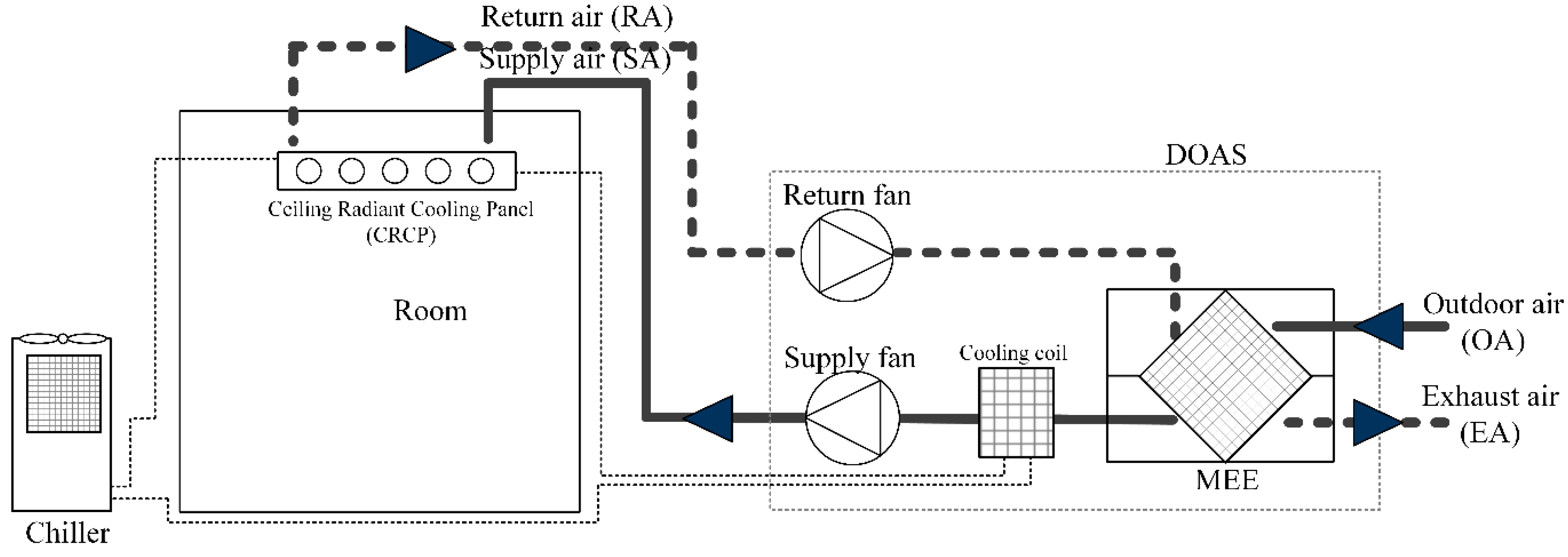
Figure 5 presents the schematic of the conventional DOAS with CRCP. In the DOAS, the hot and humid OA is pre-dehumidified and pre-cooled by the MEE, and then the cooling coil is activated to meet the target SA dew-point temperature (DPT). The target SA DPT is set to maintain the space humidity level. The CRCP is responsible for accommodating the remaining space sensible cooling load.
3.3. Liquid Desiccant Unit
The performance of the LD unit was analyzed using a finite difference model. The governing equations of an internally cooled or heated type LD unit are similar to those previously published [44,45]. In this research, the heat transfer between the desiccant solution and the cold side or hot side of the THP was considered.
The models for the internally cooled absorber or heated regenerator were experimentally verified, and they have been used to analyze adiabatic-type absorbers and regenerators [46]. It was seen that the bias difference between the model and experiments was less than 10%. These models were derived for the mass and energy balances, assuming that both the heat and mass transfers are steady-state, the THPLD is thermally isolated, thermodynamic equilibrium is obtained at the air-solution interfaces, the working channel contains wicking material, the model ignores the liquid desiccant film thickness, and the heat of THP is transferred only in the desiccant solution.
Figure 6 shows the control volume and the schematic of the heat and mass balances among the desiccant solution, air, and THP. In the THPLD, the desiccant solution is directly sprayed into the channels. On the cold side of the THPLD, the desiccant solution is cooled, as it is done in the absorber, and the weak desiccant solution is heated by the heat dissipated from the hot side of the THPLD, as it is done in the regenerator.
The heat and mass transfers among the surface of the plate, air, and solution can be expressed as in Equations (2)–(6). The mass conservations of the water vapor and solution are shown in Equations (2) and (3), respectively. The sensible heat, latent heat, and enthalpy exchange between the solution and air are shown in Equations (4), (5) and (6), respectively. The energy conservation between the air, solution, and THP is expressed in Equation (7).
It is assumed that the channels are made of 3-mm plastic film as a sinusoidal spacer, and paper. The paper is a composite fiber made of polyethylene phthalate sheets. This material allows the desiccant solution in the wet channel to be uniformly distributed [9].
The Nusselt number () of the channel was set to 2.14, as estimated using Equation (8). This Nusselt number is for the triangular channel having adiabatic isosceles with a uniform heat flux boundary condition [9,19]. It was assumed that the fin efficiency is zero and the apex angle (α) is 84°, which corresponds to a width-to-height ratio of 9/5.
The heat transfer coefficient () was calculated using Equation (9). The mass transfer coefficient () was estimated using the Chilron-Colburn analogy (Equation (10)).
The dehumidification rate in the absorber is controlled by adjusting the cooling-water temperature, and the regeneration rate in the regenerator is commonly controlled by changing the liquid-to-gas ratio [10]. The desiccant solution flow rate to the regenerator is modulated by the regeneration pump to meet the target concentration of the strong solution in the solution tank.
3.4. Standard THP Model
In order to evaluate the energy performance of the THP, the steady-state standard simple model, which considers a mean temperature between the hot and cold junction temperatures of the THP, was used [47]. The absorbed () and released () heat fluxes for the THP can be obtained using Equations (11) and (12), respectively.
The electric power () required to supply the THP is the difference between the absorbed and released heat fluxes (Equation (13)). In these equations, , R, and K are the Seebeck coefficient, electrical resistance, and thermal conductance of the THP at the mean temperature, respectively. I represents the electric current and is the number of legs in a THP module. The TEM is composed of several legs and the leg characteristics affect the TEM performance. R and K are estimated using Equations (14) and (15), respectively, considering the leg length (), leg section area (), thermal conductivity (), and electrical resistivity (). The coefficient of performance (COP) of the THP is the ratio between the absorbed heat and electric power (Equation (16)). This research considered a leg made of bismuth telluride (Bi2Te3) and its properties are shown in Table 2. From the literature [21], it was shown that the COP difference between the model and experiments was within 0.2. The thermal resistance between the thermoelectric module and fin plate was set to 0.0161 K/W.
Figure 6 shows the simple, steady-state, and one-dimensional heat transfer process of a THP for a liquid desiccant system. The solution that enters the absorber is cooled by the cold side of the THP and then, the heat is dissipated on the hot side of the THP to the solution that enters the regenerator. The plate for heat exchange is attached to the cold and hot sides of the THP. The plate of the THPLD is made of corrosion-resistant stainless steel (thickness of 0.25 mm, thermal conductivity of 24.9 W/(m·K)) [48]. The thermal contact resistance () between the cold side or hot side of the TEM and plate of the THPLD is 16.1 K/W. Depending on the required solution cooling and heating energies (i.e., and , respectively) in the LD unit, the hot side () and cold side () plate surface temperatures can be estimated in Equations (17) and (18), respectively.
3.5. Membrane Enthalpy Exchanger
In this study, the ε-NTU based simplified model proposed by Zhang and Niu [49] was used to evaluate the sensible effectiveness () and latent effectiveness () of the MEE (Equations (19) and (20), respectively). As shown in Equations (21) and (22), the sensible effectiveness () and latent effectiveness () of the MEE was calculated using the number of transfer units (NTUs). This model showed that the average errors between the predicted and experimental results were 7.3% and 8.6% for sensible and latent effectiveness, respectively. The NTU was set to 4.2, based on the manufacturer’s data [50], and the ratio of the total NTU for moisture to that for sensible heat () is 0.45.
where:
3.6. Chiller Model
This research utilized the DOE-2.1 chiller model used in the EnergyPlus program [51]. This model is an empirical model developed by Hydeman et al. [52] as part of the CoolToolsTM project. This model returns the thermal performance of the chiller and the power consumption of the compressor. From the literature [52], this model predicts the thermal and electric performance within 4.2% of deviation compared with the experimental results. As shown in Equations (23)–(28), this model uses three major performance curves to evaluate the cooling capacity function of the temperature curve (CAPFT), energy input to the cooling output ratio function of the temperature curve (EIRFT), and energy input to the cooling output ratio function of part load ratio curve (EIRFPLR) depending on the exiting chiller water temperature (), entering condenser fluid temperature (), and part load ratio (PLR). Table 3 presents the coefficients of the chiller model.
3.7. Ceiling Radiant Cooling Panel Model
The cooling capacity of the CRCP () was calculated using Equation (29), which is a practical model developed by Jeong et al. [53]. The model coefficients are shown in Table 4. This model contains mixed convection and radiant heat transfer in the radiant panel. The simplified cooling-capacity estimation model for the suspended metal CRCP was derived by using the 2k-factorial experimental design method and validated by the analytical panel model. This linear regression equation model is a function of eight major design parameters. The valid ranges of the thirteen independent parameters in Equation (29) are a tube spacing () of 0.15–0.3 m, a panel thickness () of 0.0007–0.002 m, a panel thermal conductivity () of 60–206 W/m·°C, an inlet fluid temperature () of 10–18 °C, a diffuser discharge velocity () of 2–6 m/s, a diffuser width () of 0.2–0.8 m, a room air temperature () of 26–28 °C, and a room position index () of 0.5–3. The R2 value for this model is 0.98, and this model was validated with the manufacturer’s data.
For the simulation conditions, the tube spacing was set at 0.15 m, the aluminum panel thickness was 1.0 mm, and the thermal conductivity was 206 W/m·°C. The inlet fluid temperature was set at 15 °C and the diffuser discharge velocity was 2 m/s. The diffuser width was 0.5 m and the room position index was set at 1. The tube outside and inside diameter were 0.015 m and 0.01 m, respectively. The fluid velocity inside the copper tube was 0.3 m/s and the tube spacing was 0.15 m. It was determined that the pipe length per panel area (m/m2) was 3.3 m/m2 [54]. The head loss per unit length for the copper tube was set to 30 Pa/m [55].
3.8. Fan and Pump
The conventional DOAS uses a chilled water pump for the cooling coil and CRCP. The proposed system uses three pumps, for the desiccant solution in the absorber and regenerator and for the chilled water in the CRCP. In this research, the pump efficiency was assumed to be 60% and the head losses for the pumps are shown in Table 5. The pump power can be estimated using Equation (30).
The conventional DOAS operates two fans, for the supply and return air. The proposed system uses one additional fan for the regenerator of the THPLD. The fan efficiency was assumed to be 60% and the air-side static pressure losses of the components are shown in Table 6. The fan power was also calculated using Equation (31).
4. Results
4.1. Design of the THP for the LD System
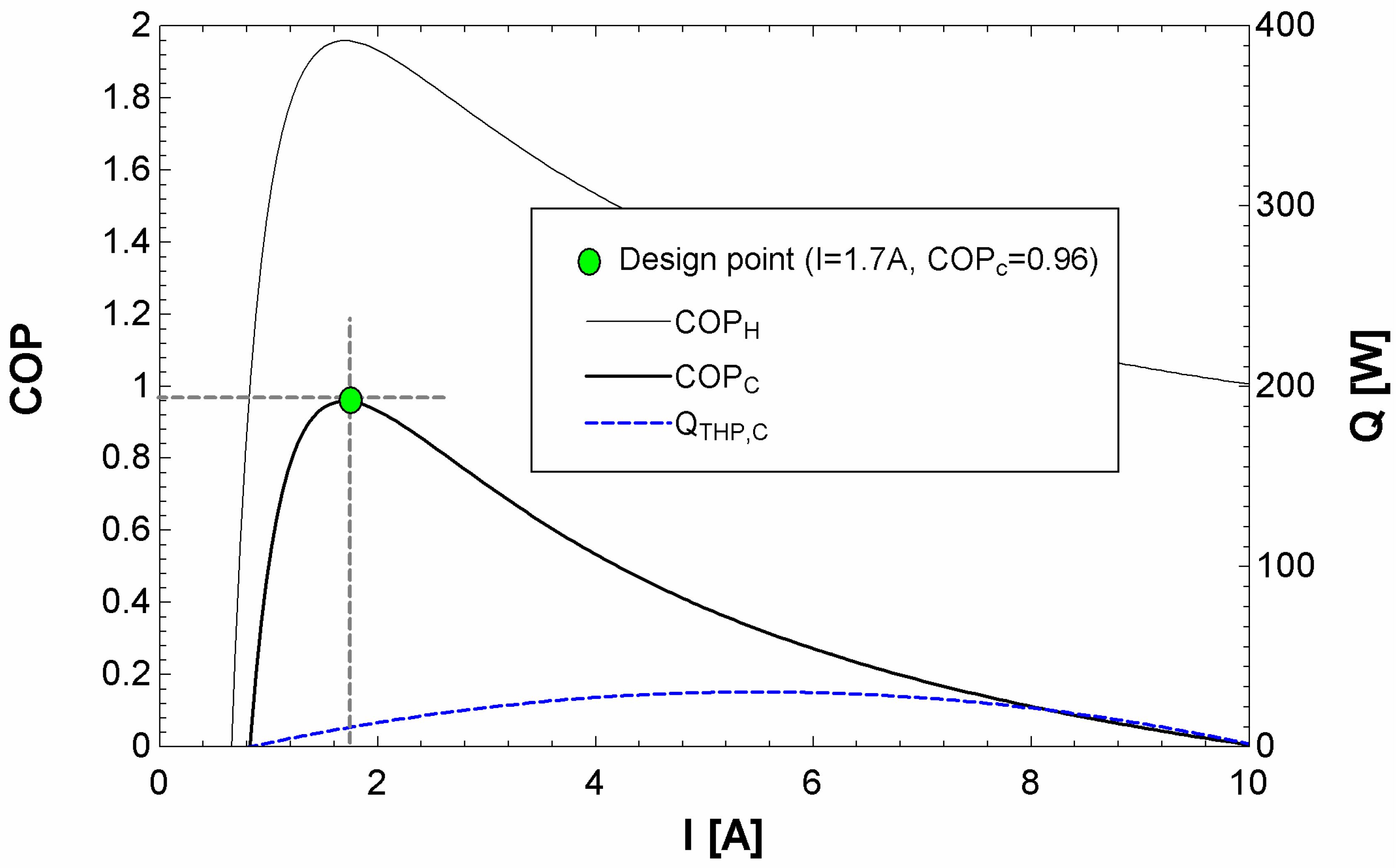
The optimum operating current for the TEM of the THPLD was designed as shown in Figure 7. The operating plate surface temperatures of the cold and hot sides were set to 20 °C and 50 °C, respectively. It was found that the maximum cooling COP was 0.96 and the required number of TEMs was 260. In order to operate the THP under a partial load, the current was varied (Figure 8b) and binary control was adopted (Figure 8a) to maintain a COP of the THP of nearly 1. It was demonstrated that the COP of the THP was maintained in the range of 0.8–1.2 during the operation (Figure 8c).
4.2. CRCP Design of System Cases
In the conventional DOAS, when the latent load of the OA is removed by the cooling coil, and the SA is delivered to the conditioned space without reheating, a portion of the room sensible cooling load can be accommodated by the SA of the DOAS. This leads to a reduction of the parallel cooling done by the CRCP.
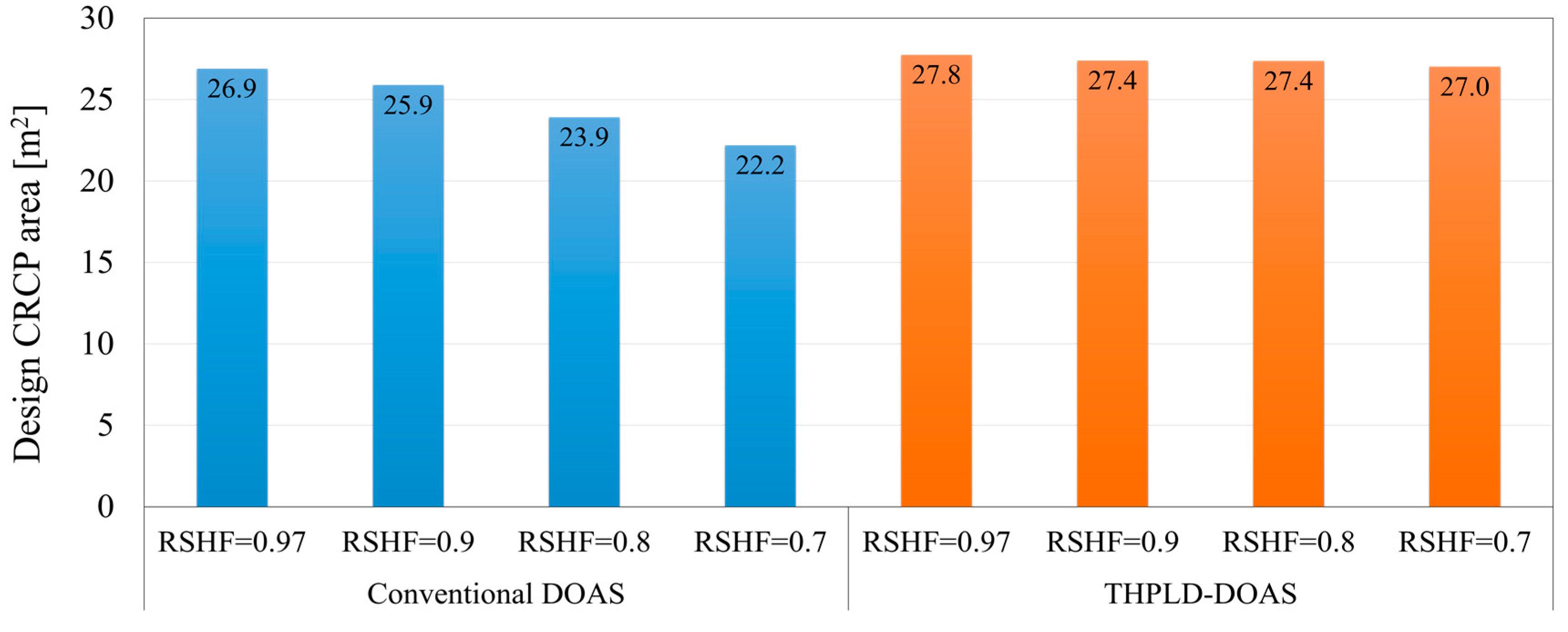
Figure 9 shows the required CRCP areas estimated for the various operating conditions of the conventional DOAS and the proposed system. It was found that the CRCP area required for parallel cooling inside the conditioned space decreased with the RSHF in the conventional DOAS system. This is because, in the conventional DOAS, the supply air should be dehumidified to a greater extent by the cooling coil for the space with lower RSHF, which leads to a lower SA temperature that provides more sensible cooling inside the space.
On the other hand, the THPLD in the proposed system dehumidifies the supply air and delivers it to the conditioned space at the neutral temperature. The entire room sensible cooling load should be accommodated by the CRCP. Consequently, it was found that the required CRCP area in the proposed system is not strongly affected by the RSHF.
4.3. Operating Energy Consumption in the Cooling Season
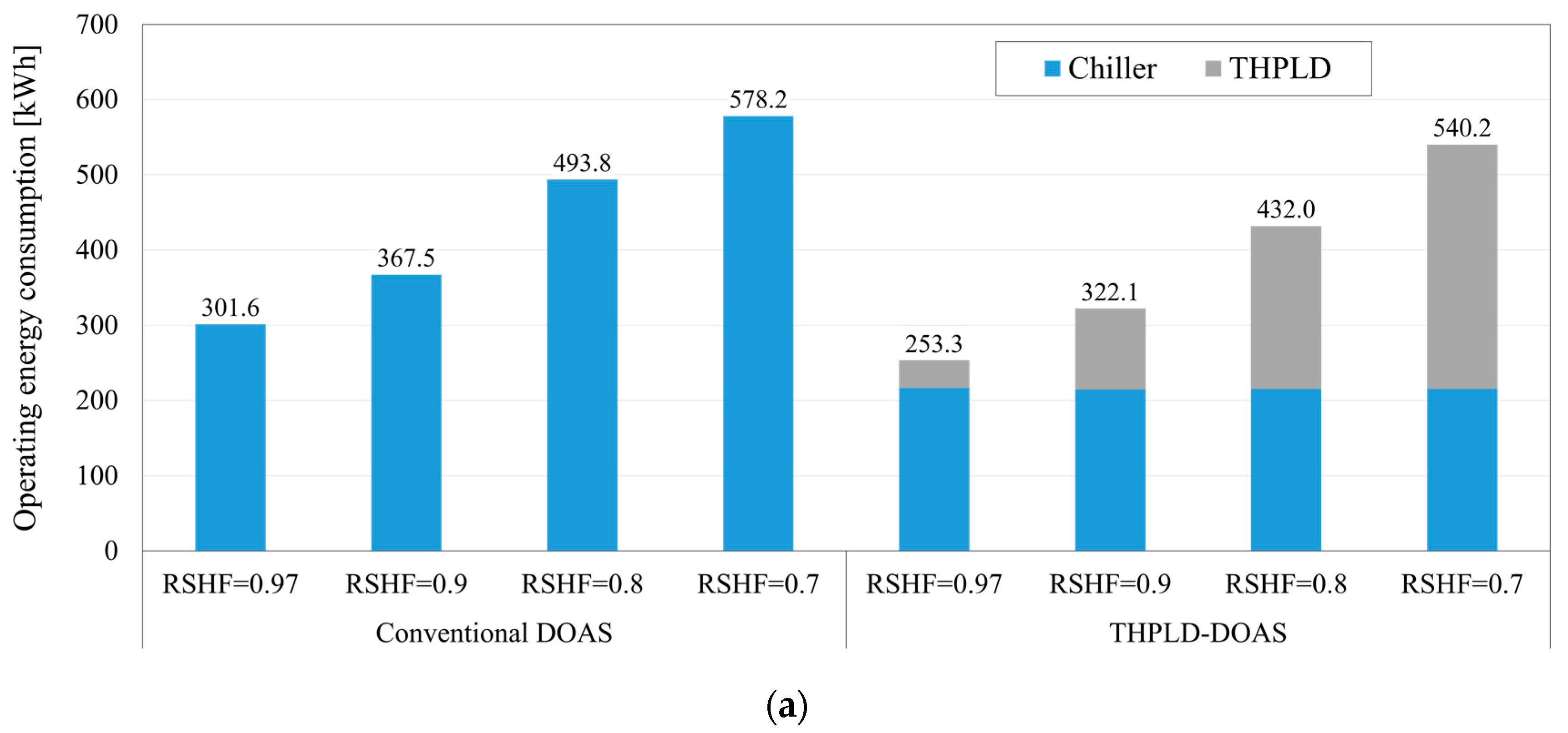
Figure 10 shows the operating energy consumption for each component of the systems during the cooling season (i.e., July and August). The chiller COP for the CRCP in the proposed system was higher than that for the cooling coil in the conventional DOAS, which was caused by the higher temperature of the entering chilled water of the CRCP in the proposed system than that of the cooling coil in the conventional DOAS. Consequently, as shown in Figure 10a, the proposed system reduced the chiller energy consumption by 6.6% to 16.0% compared to the conventional DOAS.
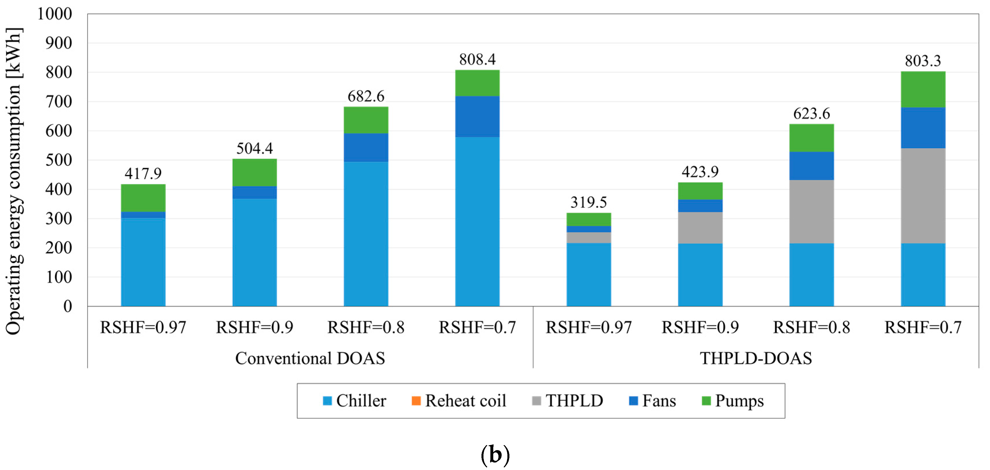
Figure 10b presents the total operating energy consumption of the systems. It was found that the proposed system could save from 0.6% to 23.5% of operating energy over the conventional DOAS, owing to the chiller energy savings.
5. Conclusions
In this study, we developed a DOAS-CRCP integrated with a THPLD system to enhance the energy performance of the conventional DOAS system. The THPLD system was also proposed to provide cooling and heating sources for continuous operation of the LD system. In order to evaluate the operating energy saving potential of the proposed system, the conventional DOAS-CRCP was simulated under various RSHF conditions. For the detailed simulation of the building, the commercial simulation program TRNSYS 17 was used. Subsequently, the systems were evaluated using the models for each component that were experimentally validated. It was found that the COP of the THP ranged from 0.8 to 1.2 for maintaining the dehumidification rate under the 0.8 RSHF condition. Simultaneously, the COP of the conventional cooling coil ranged from 4.5 to 5.5. The conventional cooling coil should be cooled at DPT of the supply air condition for maintaining the target dehumidification rate; however, the THPLD required only 20 °C at the cold side for this purpose. This led to chiller energy savings between 6.6% and 16.0% in the proposed system compared with the conventional DOAS. Consequently, it was also shown that the proposed system reduced the total operating energy by 0.6% to 23.5% compared to the conventional DOAS, depending on the RSHF conditions.
Acknowledgments
This work was supported by the National Research Foundation (NRF), grant (no. 2015R1A2A1A05001726), the Korea Agency for Infrastructure Technology Advancement (KAIA) (grant 17CTAP-C116268-02), and the Korea Institute of Energy Technology Evaluation and Planning (KETEP) of the Republic of Korea (no. 20173010140800).
Author Contributions
Min-Hwi Kim, Joon-Young Park, and Jae-Weon Jeong performed the simulation and data analysis, and wrote this paper based on the obtained results.
Conflicts of Interest
The authors declare no conflict of interest.
Nomenclature
| Apex angle (°) | |
| Seebeck coefficient (V/K) | |
| Specific heat (kj/kg·°C) | |
| Diffusivity of water vapor in air (m2/s) | |
| Hydraulic diameter (m) | |
| Room position index | |
| Height (m) | |
| Enthalpy (kj/kg) | |
| Heat transfer coefficient (W/m2·°C) | |
| Mass transfer coefficient (W/m2·°C) | |
| Electric current (A) | |
| Thermal conductance (W/K) | |
| Conduction heat transfer coefficient of air (W/m·K) | |
| Panel thermal conductivity (W/m·°C) | |
| Leg length (m) | |
| Mass flow rate (kg/s) | |
| Nusselt number | |
| NTU | Number of transfer units |
| Density (kg/m3) | |
| Electrical resistivity of the TEM (·m) | |
| Power (W) | |
| Heat flux (kw) | |
| Electrical resistance () | |
| Thermal contact resistance (K/W) | |
| Leg section area (m2) | |
| Temperature (°C) | |
| Diffuser discharge velocity (m/s) | |
| Diffuser width (m) | |
| Humidity ratio (kg/kg) | |
| Concentration | |
| Height of the control volume (m) | |
| Thermal conductivity of the TEM (W/m·K) | |
| Effectiveness (%) | |
| Tube spacing (m) | |
| Ratio of the total number of transfer units for moisture to that for sensible heat | |
| Panel thickness (m) |
Abbreviations
| AC | Air conditioning |
| CAPFT | Cooling capacity function of the temperature curve |
| COP | Coefficient of performance |
| CRCP | Ceiling radiant cooling panel |
| DOAS | Dedicated outdoor air system |
| DPT | Dew point temperature |
| EES | Engineering equation solver |
| EIRFT | Energy input to the cooling output ratio function of the temperature curve |
| EIRFPLR | Energy input to the cooling output ratio function of the part load ratio curve |
| HVAC | Heating ventilating and air conditioning |
| LD | Liquid desiccant |
| MEE | Membrane enthalpy exchanger |
| OA | Outdoor air |
| PLR | Part load ratio |
| RSHF | Room sensible heat factor |
| SA | Supply air |
| TEM | Thermoelectric module |
| THP | Thermoelectric heat pump |
| TRNSYS | Transient systems simulation |
Greek Symbols
| Subscripts | |
| Air | |
| Absorber | |
| Cold side | |
| Chilled water | |
| Chiller | |
| Condenser | |
| Entering | |
| Hot side | |
| Leaving | |
| Latent | |
| max | Maximum |
| min | Minimum |
| Plate | |
| Primary | |
| Return air | |
| Regenerator | |
| Reference | |
| Solution | |
| Saturation | |
| Secondary | |
| Sensible | |
| Vapor | |
| Water | |
References
- Jeong, J.W.; Mumma, S. Energy conservation benefits of a dedicated outdoor air system with parallel sensible cooling by ceiling radiant panels. ASHRAE Trans. 2003, 109, 627–636. [Google Scholar]
- Deng, S.; Lau, J.; Jeong, J.W. Do all DOAS configurations provide the same benefits? ASHRAE J. 2014, 56, 52–57. [Google Scholar]
- Zhang, L.; Zhang, Y.F. Research on energy saving potential for dedicated ventilation systems based on heat recovery technology. Energies 2014, 7, 4261–4280. [Google Scholar] [CrossRef]
- Zhang, L.; Zhang, Y.F. Research on heat recovery technology for reducing the energy consumption of dedicated ventilation systems: An application to the operating model of a laboratory. Energies 2016, 9, 24. [Google Scholar] [CrossRef]
- Kawamoto, K.; Cho, W.; Kohno, H.; Koganei, M.; Ooka, R.; Kato, S. Field study on humidification performance of a desiccant air-conditioning system combined with a heat pump. Energies 2016, 9, 89. [Google Scholar] [CrossRef]
- Coad, W.J. Conditioning ventilation air for improved performance and air quality. HPAC Eng. 1999, 71, 49–56. [Google Scholar]
- Khattar, M.K.; Brandemuehl, M.J. Separating the V in HVAC: A dual-path approach. ASHRAE J. 2002, 44, 37–42. [Google Scholar]
- Ge, G.; Xiao, F.; Wang, S. Optimization of a liquid desiccant based dedicated outdoor air-chilled ceiling system serving multi-zone spaces. Build. Simul. 2012, 5, 257–266. [Google Scholar] [CrossRef]
- Liu, X.; Li, Z.; Jiang, Y.; Lin, B. Annual performance of liquid desiccant based independent humidity control HVAC system. Appl. Therm. Eng. 2006, 26, 1198–1207. [Google Scholar] [CrossRef]
- Xiao, F.; Ge, G.; Niu, X. Control performance of a dedicated outdoor air system adopting liquid desiccant dehumidification. Appl. Energy 2011, 88, 143–149. [Google Scholar] [CrossRef]
- Ge, G.; Xiao, F.; Xu, X. Model-based optimal control of a dedicated outdoor air-chilled ceiling system using liquid desiccant and membrane-based total heat recovery. Appl. Energy 2011, 88, 4180–4190. [Google Scholar] [CrossRef]
- Goetzler, W.; Zogg, R.; Young, J.; Johnson, C. Energy Savings Potential and RD&D Opportunities for Non-Vapor-Compression HVAC Technologies; Navigant Consulting Inc.; US Department of Energy: Washington, DC, USA, 2014.
- Kim, M.H.; Park, J.S.; Jeong, J.W. Energy saving potential of liquid desiccant in evaporative-cooling-assisted 100% outdoor air system. Energy 2013, 59, 726–736. [Google Scholar] [CrossRef]
- Crofoot, L.; Harrison, S. Performance evaluation of a liquid desiccant solar air conditioning system. Energy Procedia 2012, 30, 542–550. [Google Scholar] [CrossRef]
- Abdel-Salam, A.H.; Ge, G.; Simonson, C.J. Thermoeconomic performance of a solar membrane liquid desiccant air conditioning system. Sol. Energy 2014, 102, 56–73. [Google Scholar] [CrossRef]
- Niu, X.; Xiao, F.; Ma, Z. Investigation on capacity matching in liquid desiccant and heat pump hybrid air-conditioning systems. Int. J. Refrig. 2012, 35, 160–170. [Google Scholar] [CrossRef]
- Zhang, L.-Z.; Zhang, N. A heat pump driven and hollow fiber membrane-based liquid desiccant air dehumidification system: Modelling and experimental validation. Energy 2014, 65, 441–451. [Google Scholar] [CrossRef]
- Bergero, S.; Chiari, A. On the performances of a hybrid air conditioning system in different climatic conditions. Energy 2011, 36, 5261–5273. [Google Scholar] [CrossRef]
- Liu, Z.; Zhang, L.; Gong, G.; Li, H.; Tang, G. Review of solar thermoelectric cooling technologies for use in zero energy buildings. Energy Build. 2015, 102, 207–216. [Google Scholar] [CrossRef]
- Chen, L.; Li, J.; Sun, F.; Wu, C. Performance optimization for a two-stage thermoelectric heat-pump with internal and external irreversibilities. Appl. Energy 2008, 85, 641–649. [Google Scholar] [CrossRef]
- Riffat, S.B.; Ma, X.; Wilson, R. Performance simulation and experimental testing of a novel thermoelectric heat pump system. Appl. Therm. Eng. 2006, 26, 494–501. [Google Scholar] [CrossRef]
- Lai, H.; Pan, Y.; Chen, J. Optimum design on the performance parameters of a two-stage combined semiconductor thermoelectric heat pump. Semicond. Sci. Technol. 2003, 19, 17. [Google Scholar] [CrossRef]
- Khire, R.A.; Messac, A.; Van Dessel, S. Design of thermoelectric heat pump unit for active building envelope systems. Int. J. Heat Mass Transf. 2005, 48, 4028–4040. [Google Scholar] [CrossRef]
- Kim, Y.W.; Ramousse, J.; Fraisse, G.; Dalicieux, P.; Baranek, P. Optimal sizing of a thermoelectric heat pump (THP) for heating energy-efficient buildings. Energy Build. 2014, 70, 106–116. [Google Scholar] [CrossRef]
- Han, T.; Gong, G.; Liu, Z.; Zhang, L. Optimum design and experimental study of a thermoelectric ventilator. Appl. Therm. Eng. 2014, 67, 529–539. [Google Scholar] [CrossRef]
- Yadav, Y.K. Vapour-compression and liquid-desiccant hybrid solar space-conditioning system for energy conservation. Renew. Energy 1995, 6, 719–723. [Google Scholar] [CrossRef]
- Kinsara, A.A.; Elsayed, M.M.; Al-Rabghi, O.M. Proposed energy-efficient air-conditioning system using liquid desiccant. Appl. Therm. Eng. 1996, 16, 791–806. [Google Scholar] [CrossRef]
- Kinsara, A.A.; Al-Rabghi, O.M.; Elsayed, M.M. Parametric study of an energy efficient air conditioning system using liquid desiccant. Appl. Therm. Eng. 1998, 18, 327–335. [Google Scholar] [CrossRef]
- Ahmed, C.K.; Gandhidasan, P.; Al-Farayedhi, A.A. Simulation of a hybrid liquid desiccant based air-conditioning system. Appl. Therm. Eng. 1997, 17, 125–134. [Google Scholar] [CrossRef]
- Dai, Y.J.; Wang, R.Z.; Zhang, H.F.; Yu, J.D. Use of liquid desiccant cooling to improve the performance of vapor compression air conditioning. Appl. Therm. Eng. 2001, 21, 1185–1202. [Google Scholar] [CrossRef]
- Ani, F.N.; Badawi, E.M.; Kannan, K.S. The effect of absorber packing height on the performance of a hybrid liquid desiccant system. Renew. Energy 2005, 30, 2247–2256. [Google Scholar] [CrossRef] [Green Version]
- Ma, Q.; Wang, R.Z.; Dai, Y.J.; Zhai, X.Q. Performance analysis on a hybrid air-conditioning system of a green building. Energy Build. 2006, 38, 447–453. [Google Scholar] [CrossRef]
- Zhang, L.; Dang, C.; Hihara, E. Performance analysis of a no-frost hybrid air conditioning system with integrated liquid desiccant dehumidification. Int. J. Refrig. 2010, 33, 116–124. [Google Scholar] [CrossRef]
- Bergero, S.; Chiari, A. Performance analysis of a liquid desiccant and membrane contactor hybrid air-conditioning system. Energy Build. 2010, 42, 1976–1986. [Google Scholar] [CrossRef]
- Secretariat, O. The Montreal Protocol on Substances that Deplete the Ozone Layer; United Nations Environment Program: Nairobi, Kenya, 2000. [Google Scholar]
- Creazzo, J.A.; Hammel, H.S.; Cicalo, K.J.; Schindler, P. Zero-ODP blowing agents for polyurethane foams. J. Cell. Plast. 1995, 31, 154–176. [Google Scholar] [CrossRef]
- Luo, Y.; Zhang, L.; Liu, Z.; Wang, Y.; Meng, F.; Xie, L. Modeling of the surface temperature field of a thermoelectric radiant ceiling panel system. Appl. Energy 2016, 162, 675–686. [Google Scholar] [CrossRef]
- Liu, Z.B.; Zhang, L.; Gong, G.C.; Han, T.H. Experimental evaluation of an active solar thermoelectric radiant wall system. Energy Convers. Manag. 2015, 94, 253–260. [Google Scholar] [CrossRef]
- Jeong, J.W.; Choi, A.; No, S.T. Improvement in demand-controlled ventilation simulation on multi-purposed facilities under an occupant based ventilation standard. Simul. Model. Pract. Theory 2010, 18, 51–62. [Google Scholar] [CrossRef]
- Holder, H.W. DOAS & humidity control. ARSHFAE J. 2008, 50, 34. [Google Scholar]
- Klein, S.A.; Beckman, W.A.; Mitchell, J.W.; Duffie, J.A. TRNSYS 17—A Transient System Simulation Program; User Manual; Solar Energy Laboratory, University of Wisconsin-Madison: Madison, WI, USA, 2009. [Google Scholar]
- Klein, S.A.; Alvarado, F.L. EES: Engineering Equation Solver for the Microsoft Windows Operating System; F-Chart Software: Madison, WI, USA, 1992. [Google Scholar]
- Li, C.L.; Chung, S.L. Enthalpy-based automatic temperature control for automobiles. In Proceedings of the 2009 IEEE Control Applications, (CCA) & Intelligent Control, (ISIC), St. Petersburg, Russia, 8–10 July 2009; pp. 222–227. [Google Scholar]
- Yin, Y.; Zhang, X.; Peng, D.; Li, X. Model validation and case study on internally cooled/heated dehumidifier/regenerator of liquid desiccant systems. Int. J. Therm. Sci. 2009, 48, 1664–1671. [Google Scholar] [CrossRef]
- Luo, Y.; Yang, H.; Lu, L.; Qi, R. A review of the mathematical models for predicting the heat and mass transfer process in the liquid desiccant dehumidifier. Renew. Sustain. Energy Rev. 2014, 31, 587–599. [Google Scholar] [CrossRef]
- Liu, J.; Liu, X.; Zhang, T. Performance comparison of three typical types of internally-cooled liquid desiccant dehumidifiers. Build. Environ. 2016, 103, 134–145. [Google Scholar] [CrossRef]
- Ramousse, J.; Sgorlon, D.; Fraisse, G.; Perier-Muzet, M. Analytical optimal design of thermoelectric heat pumps. Appl. Therm. Eng. 2015, 82, 48–56. [Google Scholar] [CrossRef]
- Product Sheet. Available online: http://www.aksteel.com/pdf/markets_products/stainless/martensitic/420_data_sheet.pdf (accessed on 30 August 2017).
- Zhang, L.Z.; Niu, J.L. Effectiveness correlations for heat and moisture transfer processes in an enthalpy exchanger with membrane cores. J. Heat Transf. 2002, 124, 922–929. [Google Scholar] [CrossRef]
- RenewAire, RenewAire LLC. Available online: http://www.renewaire.com/ (accessed on 31 August 2017).
- U.S. Department of Energy. Building Technologies Program; U.S. Department of Energy: Washington, DC, USA, 2013.
- Hydeman, M.; Webb, N.; Sreedharan, P.; Blanc, S. Development and testing of a reformulated regression-based electric chiller model/Discussion. ARSHFAE Trans. 2002, 108, 1118. [Google Scholar]
- Jeong, J.W.; Mumma, S.A. Practical cooling capacity estimation model for a suspended metal ceiling radiant cooling panel. Build. Environ. 2007, 42, 3176–3185. [Google Scholar] [CrossRef]
- HVAC Fundamentals; ASHRAE Handbook; American Society of Heating, Refrigerating and Air-Conditioning Engineers, Inc.: Atlanta, GA, USA, 2017.
- Lowenstein, A.; Slayzak, S.; Kozubal, E. A zero carryover liquid-desiccant air conditioner for solar applications. In Proceedings of the International Solar Energy Conference, Denver, CO, USA, 8–13 July 2006. [Google Scholar]
Figure 1.
Simple configuration of a TEM.

Figure 2.
Schematic of a THPLD.
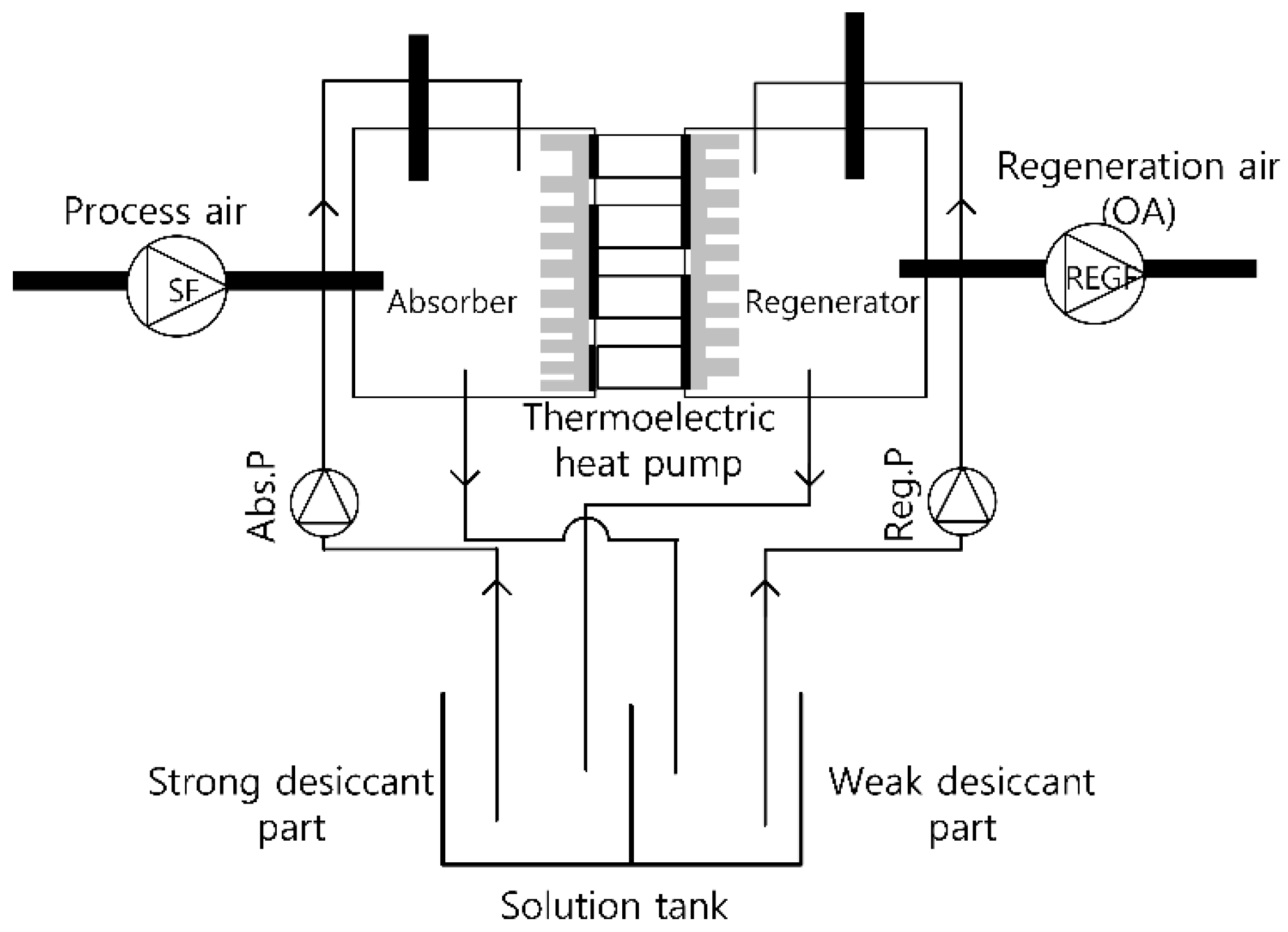
Figure 3.
Schematic of a DOAS integrated with the THPLD.

Figure 4.
Simulation process and model overview.

Figure 5.
Conventional DOAS with a CRCP.

Figure 6.
Schematic of the heat and mass balance model for the THPLD.
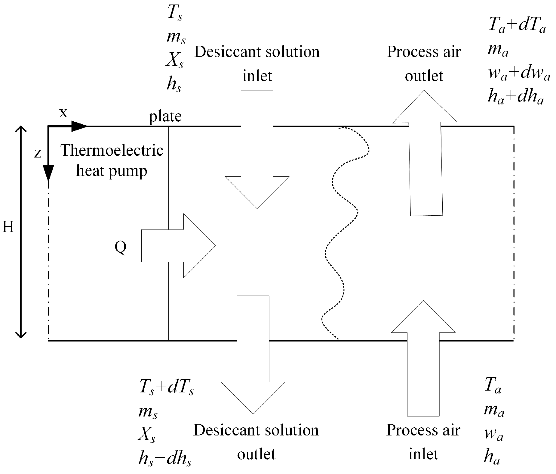
Figure 7.
Design point of the TEC module.

Figure 8.
Design and operating profiles of the THPLD system during the cooling season (RSHF = 0.8): (a) THP design point; (b) control point of I; and (c) COP profile of the THP.
Figure 8.
Design and operating profiles of the THPLD system during the cooling season (RSHF = 0.8): (a) THP design point; (b) control point of I; and (c) COP profile of the THP.
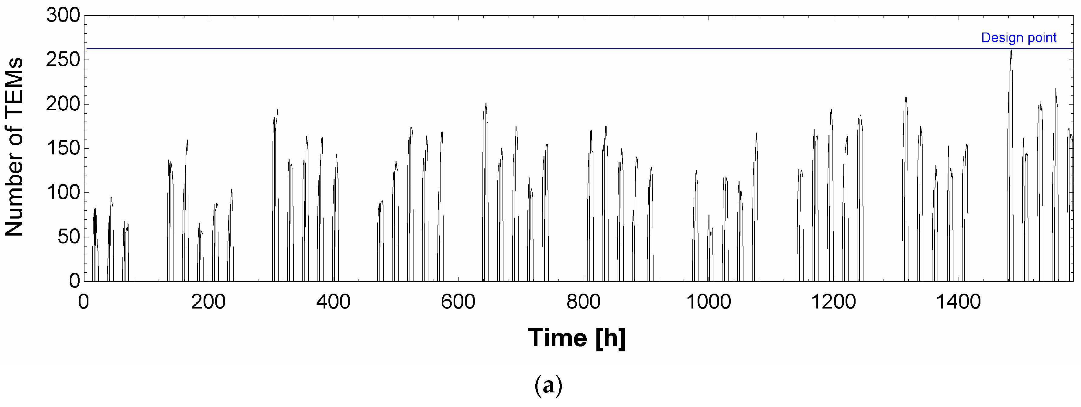
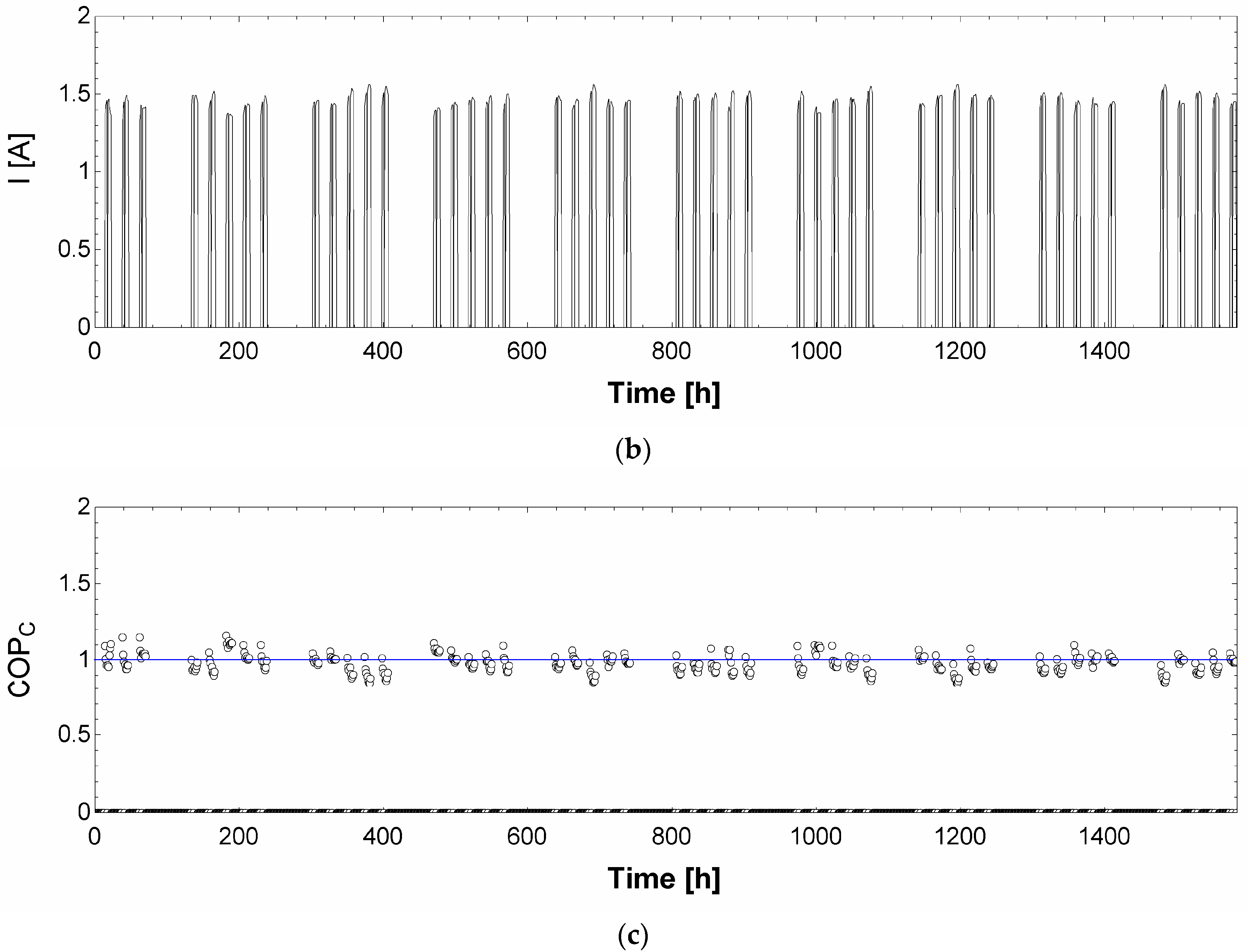
Figure 9.
Required CRCP area in the conventional DOAS and the proposed system.

Figure 10.
Operating energy consumptions of the systems: (a) chiller and THPLD system energy consumptions; and (b) total energy consumption.
Figure 10.
Operating energy consumptions of the systems: (a) chiller and THPLD system energy consumptions; and (b) total energy consumption.


Table 1.
Model building parameters.
| Location | Seoul, Republic of Korea | ||||
|---|---|---|---|---|---|
| Floor area | Office area | 42 m2 | |||
| U-value | Exterior wall | 0.511 W/m2K | |||
| Roof | 0.316 W/m2K | ||||
| Window to wall ratio | 0.5 | ||||
| RSHF | 0.97 | 0.9 | 0.8 | 0.7 | |
| Ventilation rate | 84 m3/h | 168 m3/h | 378 m3/h | 546 m3/h | |
| Lighting density | 13 W/m2 | ||||
| Infiltration | 0.3 air changes per hour (ACH) | ||||
| Schedule | 07:00–22:00, five days a week | ||||
| Indoor air condition (Summer) | Dry-bulb temperature (DBT): 26 °C, Relative humidity (RH): 50% | ||||
| Peak sensible cooling load | 4.5 kW | ||||
| Peak latent cooling load | 0.2 kW | 0.5 kW | 1.1 kW | 1.9 kW | |
Table 2.
Bi2Te3 properties.
| Thermal Conductivity | |
| Electrical Resistivity | |
| Seebeck Coefficient |
Table 3.
Chiller model coefficients.
| Curves | ||||||
|---|---|---|---|---|---|---|
| CAPFT | 0.958546443 | 0.035168695 | 0.000124662 | −0.00274551 | −0.00005000 | −0.00017234 |
| EIRFT | 0.732700123 | −0.00834360 | 0.000638530 | −0.00303753 | 0.000484952 | −0.00083584 |
| EIRFPLR | 0.070862846 | 0.002787560 | −0.00000891 | 0.230973399 | 1.250442176 | −0.00216102 |
Table 4.
CRCP model coefficients.
| –66.40919 | –827.67671 | 38798.58774 | 0.33094 | –9.60442 | 16.76649 |
| 81.44688 | 13.52746 | 2.08691 | 60209.13462 | 0.68300 | 31.74440 |
| –36.53724 | –164.59549 | –2216.93209 | 2220.82332 | –0.023188 | 0.024267 |
| - | - | ||||
| 0.12427 | –0.67052 | –3.32718 | 6.69694 | - | - |
Table 5.
Head losses of the system components.
| Nomenclature | Component | Head Loss |
|---|---|---|
| Solution pumps for the absorber and regenerator | 0.4 m each at 1.1 m3/h | |
| Chilled water for the cooling coil | 0.3 m |
© 2017 by the authors. Licensee MDPI, Basel, Switzerland. This article is an open access article distributed under the terms and conditions of the Creative Commons Attribution (CC BY) license (http://creativecommons.org/licenses/by/4.0/).
Share and Cite
MDPI and ACS Style
Kim, M.-H.; Park, J.-Y.; Jeong, J.-W. Energy Saving Potential of a Thermoelectric Heat Pump-Assisted Liquid Desiccant System in a Dedicated Outdoor Air System. Energies 2017, 10, 1306. https://doi.org/10.3390/en10091306
AMA Style
Kim M-H, Park J-Y, Jeong J-W. Energy Saving Potential of a Thermoelectric Heat Pump-Assisted Liquid Desiccant System in a Dedicated Outdoor Air System. Energies. 2017; 10(9):1306. https://doi.org/10.3390/en10091306
Chicago/Turabian StyleKim, Min-Hwi, Joon-Young Park, and Jae-Weon Jeong. 2017. "Energy Saving Potential of a Thermoelectric Heat Pump-Assisted Liquid Desiccant System in a Dedicated Outdoor Air System" Energies 10, no. 9: 1306. https://doi.org/10.3390/en10091306
Note that from the first issue of 2016, this journal uses article numbers instead of page numbers. See further details here.