Low Cost Position Controller for Exhaust Gas Recirculation Valve System

Department of Electrical Engineering, Kunsan National University, Gunsan 54150, Korea
*
Author to whom correspondence should be addressed.
Energies 2018, 11(8), 2171; https://doi.org/10.3390/en11082171
Submission received: 30 July 2018
/
Revised: 17 August 2018
/
Accepted: 17 August 2018
/
Published: 20 August 2018
(This article belongs to the Special Issue Intelligent Control in Energy Systems)
Abstract
:This paper proposes a position control method for a low-cost exhaust gas recirculation (EGR) valve system for automotive applications. Generally, position control systems used in automotive applications have many restrictions, such as cost and space. The mechanical structure of the actuator causes high friction and large differences between static friction and coulomb friction. When this large friction difference occurs, the position control vibrates when the controller uses a conventional linear controller such as the P or PI controller. In this paper, we introduce an inexpensive position control method that can be applied under the high-difference-friction mechanical systems. The proposed method is verified through the use of experiments by comparing it with the results obtained when using a conventional control system.
1. Introduction
Recently, many mechanical components used in vehicles have been replaced by electrical components to increase efficiency. These components are not only found in hybrid electric vehicles or electric vehicles but they have also been applied to gasoline and diesel vehicles such as Motor Driven Power Steering (MDPS) and Integrated Starter and Generator (ISG). These electric automotive components increase drive efficiency and reduce fossil fuel consumption. These changes are being applied to the transmission system and the engine valve system. Among these changes, the exhaust gas recirculation (EGR) valve is the mechanical component being targeted to replace the small DC motor [1,2,3,4,5]. However, in general, the mechanical systems using the EGR valve have a low acceptable cost and a narrow space for implementation; therefore, the electrical system including the actuator should be cost-effective and small. To achieve this, the mechanical actuating system cannot avoid being roughly designed, which implies high friction forces. Also, the difference between coulomb friction and static friction is very large, so obtaining a correct and a fast response in terms of position control is almost impossible using a conventional linear control system such as P, PI, or PID.
To achieve position control given this friction torque, some research has been proposed [6,7,8,9,10]. In [6], H infinite control and impulse control were combined for a fast control response. Robust control was achieved using a disturbance observer [7]. A fuzzy controller [8] and a neural network controller [9] were proposed to overcome this problem. In [10], an adaptive control method for friction compensation was proposed. These methods can dramatically reduce the effect of friction; however, a large number of parameters have to be set and the processing burden for realization is also complex in a low-cost drive system.
This paper proposes a position control method for a low-cost system. The general position control method for this low-cost system is a P-PI control method, as described in [11]. As mentioned above, correct and fast control cannot be achieved with this linear controller in mechanical systems that have this friction condition. Generally, in this case, feedforward compensation is adopted for improving the control performance [11,12,13]. However, these feedforward data are incorrect because of the aging of the mechanical system and environmental changes, such as temperature and humidity. Moreover, feedforward compensation can improve the dynamics of the controller; however, it cannot be the solution for unstable control performance that is caused by the difference in static and coulomb friction torque. In this paper, to achieve the stable position control, we first analyze the EGR valve mechanical model, define the cause of the vibration. Then, a proposed novel and simple algorithm that may be adapted to low-cost system to solve this problem are illustrated. Finally, we compare the performance of the conventional method to our proposed method to verify its superiority using experiments.
2. Mechanical Model of EGR Valve and Torque Measurement
2.1. Model Analysis of EGR Valve
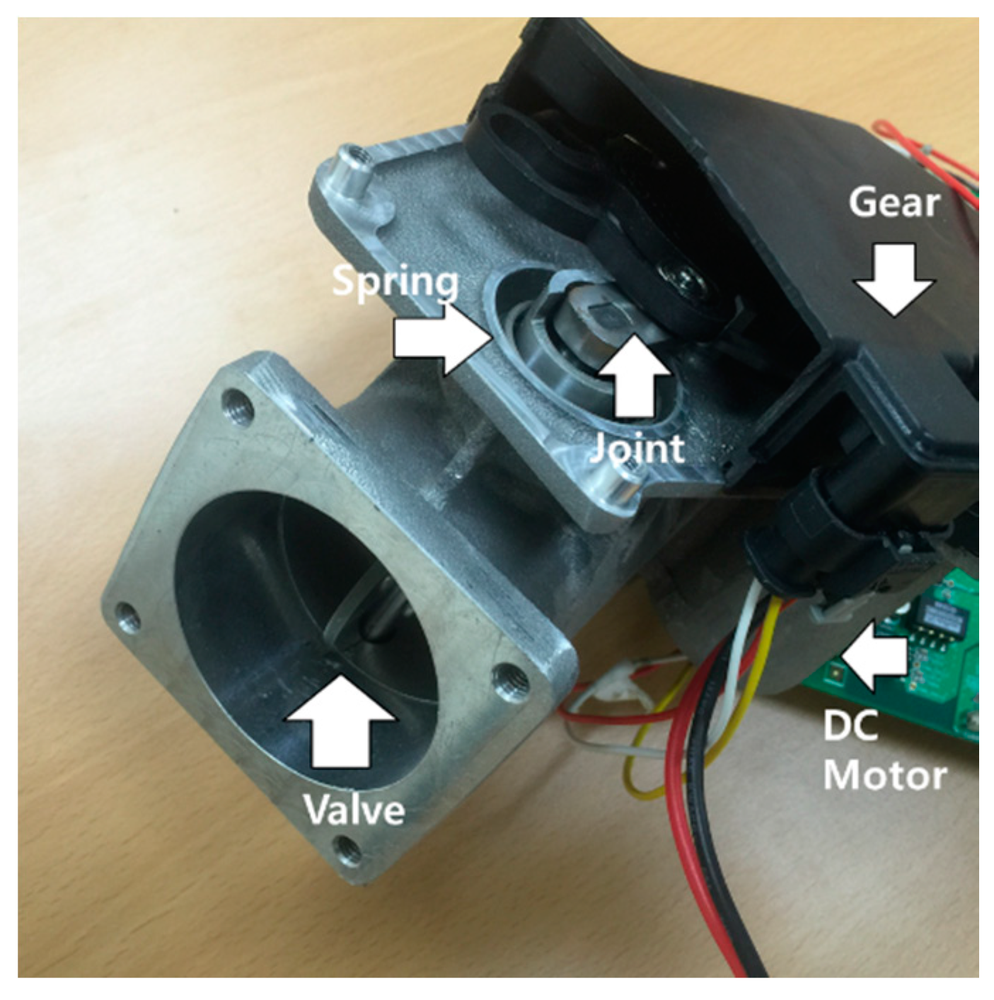
Figure 1 shows the mechanical composition of an EGR valve. In general, an EGR valve is composed of a spring for recovering the initial position of the valve, joint and gear for transforming the power from rotation to translation, a DC motor, and a throttle valve, which is the source and the actuator of the mechanical system, respectively.
First, the motor operating this system is a DC motor. Therefore, the generated torque from the motor is:
where kt is the torque constant and ia is the armature current of DC motor.
The mechanical equation of the valve system shown in Figure 1 can be described as:
where J is inertia, θr is the rotating angle, Tfric is the friction torque, Tspring is the spring torque, and TL is the load torque.
This rotating angle is transferred to a linear position by the mechanical joint and gear. The linear position x can be expressed as:
where n is the ratio of the gear, r is the joint distance, θL is the joint angle, and θL0 is the initial joint angle.
The spring force according to the linear position is described as:
where kspr is the spring character constant and x0 is the initial linear position.
This spring force can be transferred to the torque on the load side:
Then, by transferring the spring torque on the load side to the motor side, Equation (6) can be changed to:
Equation (7) indicates that the spring torque is only affected by the spring position. However, in practice, the spring torque is not only affected by the position but also by the speed direction. To apply this to Equation (7), we defined the spring coulomb friction torque as:
As shown in Equation (8), the spring coulomb friction is negative when the motor speed is in reverse. As a result, spring torque can be modelled as:
The EGR valve mechanical system is not only affected by the spring but also by the joint and the gear. The low-cost gear and the joint causing friction like a lead-screw emphasize the nonlinear static friction. In this paper, the LuGre friction model described by Yao et al. [10] is derived:
where Tge_col is the coulomb friction torque on the gear and joint, Tge_sta is the static friction torque on the gear and the joint, and ωs is the Stribeck velocity.
In this paper, these modeled load torques were measured experimentally to implement a feedforward controller as previously reported [12]. This feedforward compensation can reduce the burden on the feedback controller and can help to enhance the control performance when nonlinear load has to be controlled by a linear controller.
2.2. Measurement Procedures of Spring and Friction Torque
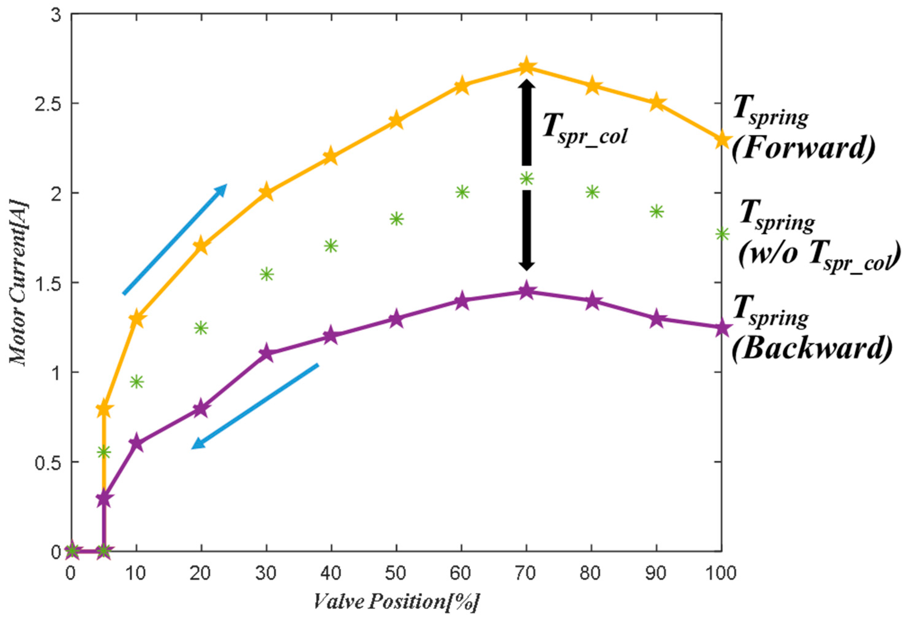
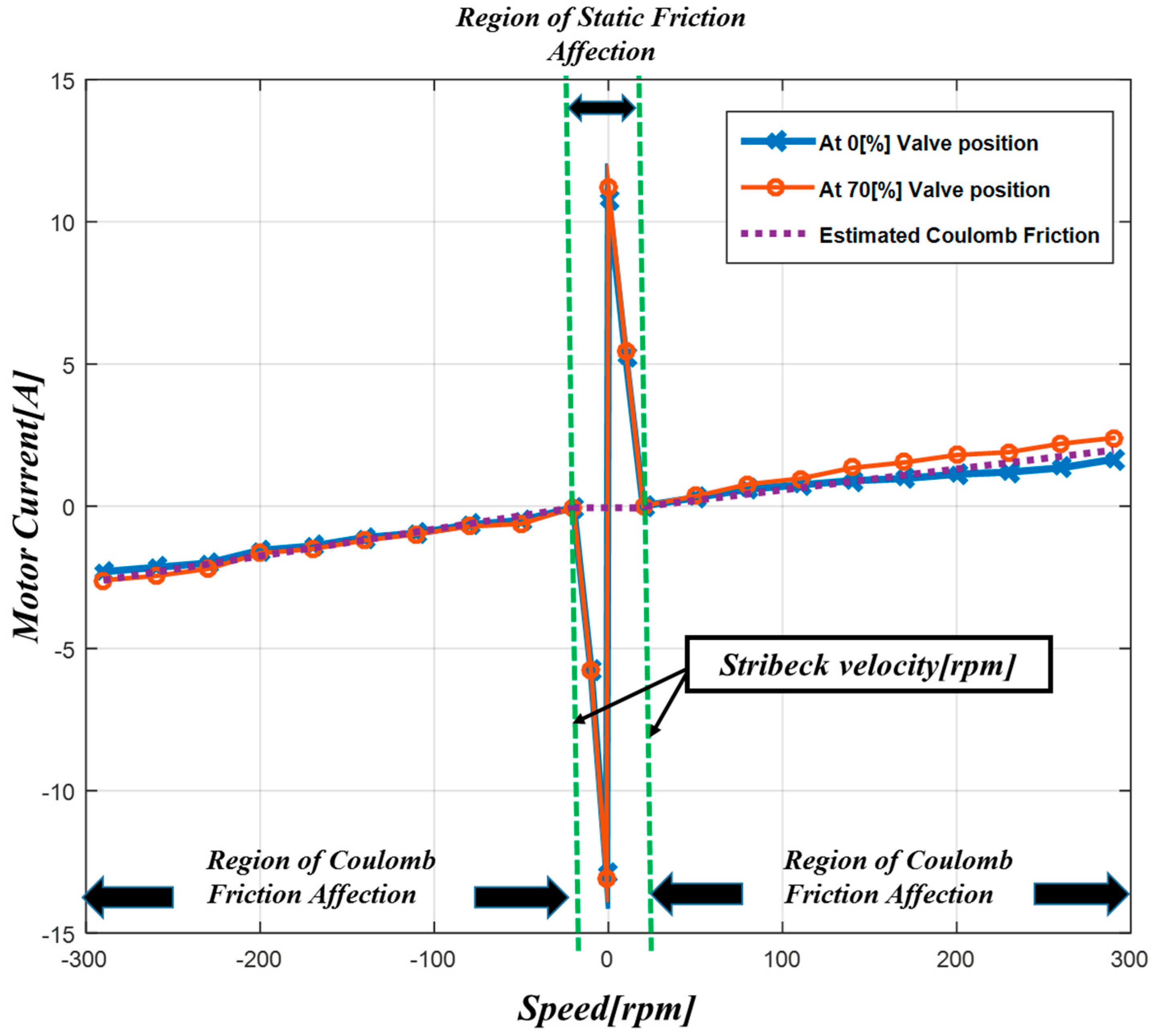
Figure 2 and Figure 3 show the measured spring torque and friction torque of the tested EGR valve, respectively. First of all, the electric torque from the motor is proportional to the DC motor current based on Equation (1). Therefore, we assumed that the current waveform can indirectly describe the generated torque. To measure the spring torque, we followed the steps below for identifying them.
- Perform speed control on the initial EGR valve position.
- Apply the speed reference from 10 rpm to 300 rpm.
- Measure the averaged current. The speed at which the lowest averaged current is observed is the Stribeck velocity. Repeat the experiment as necessary for gathering data.
- Control the motor using Stribeck velocity. The measured instantaneous current on steady state is the spring torque, with the assumption that the friction torque at Stribeck velocity can be ignored.
With the obtained spring torque, we measured the static friction torque with the following steps.
- Perform speed control started on each EGR valve position.
- Set up the small gain on the current controller in order to apply the ramp increasing current reference.
- Sudden current changes occur due to the position of the movement; measure the peak current point.
- Subtract the spring torque amount from the measurement in Step 3. The remaining value is the static friction torque.
The coulomb friction torque can be obtained with the following steps.
- Perform speed control started on the initial EGR valve position.
- Apply the speed reference from 100 rpm and 300 rpm.
- Measure the instantaneous current on the steady state of each speed.
- Subtract the instantaneous current at 100 rpm from the current at 300 rpm.
- Divide 200 rpm from the result of Step 4 for removing the spring torque component.
- Multiply the speed from the result obtained in Step 5. This is the coulomb friction torque.
As shown in Figure 2, different spring torques occurred according to the valve position direction. If the valve position direction was to open the valve, the spring torque increased due to the coulomb friction in the spring torque, which is depicted in Equation (8). Reversely, if the valve position direction was to close the valve, the spring torque decreased. Figure 3 indicates that the friction torque at each position had almost the same static friction torque. Also, the static friction in the reverse direction had different values from the positive direction value. Coulomb friction torque calculation is based on a simple principle. First, the torque equation at 300 rpm can be described as:
where ωr2 is the angular speed of 300 rpm.
If the steady state condition is only effective for identifying the coulomb friction torque, the inertia term can be neglected. With Equation (12), the torque difference that represents Step 4 can be calculated as:
where ωr1 is the angular speed of 100 rpm.
As described in Equation (5), if the positions coincide, the spring torque is not affected by the speed. Static friction torque does not interfere during the constant speed operation, so Equation (13) can be simply described as:
If the coulomb friction is proportional to the speed, it can be expressed by the coulomb friction gain and the speed. The assumption that this gain is almost the same all over the position, to simplify the coulomb friction, Equation (14) can be transformed into:
where B is the coulomb friction gain.
In this paper, we assumed that the coulomb friction occurs over the Stribeck velocity. Estimated coulomb friction gain is 0.0082 rpm/A for the forward direction and 0.0089 rpm/A for the reverse direction, respectively. Stribeck velocity of forward direction is 21 rpm and reverse direction is 17 rpm, respectively.
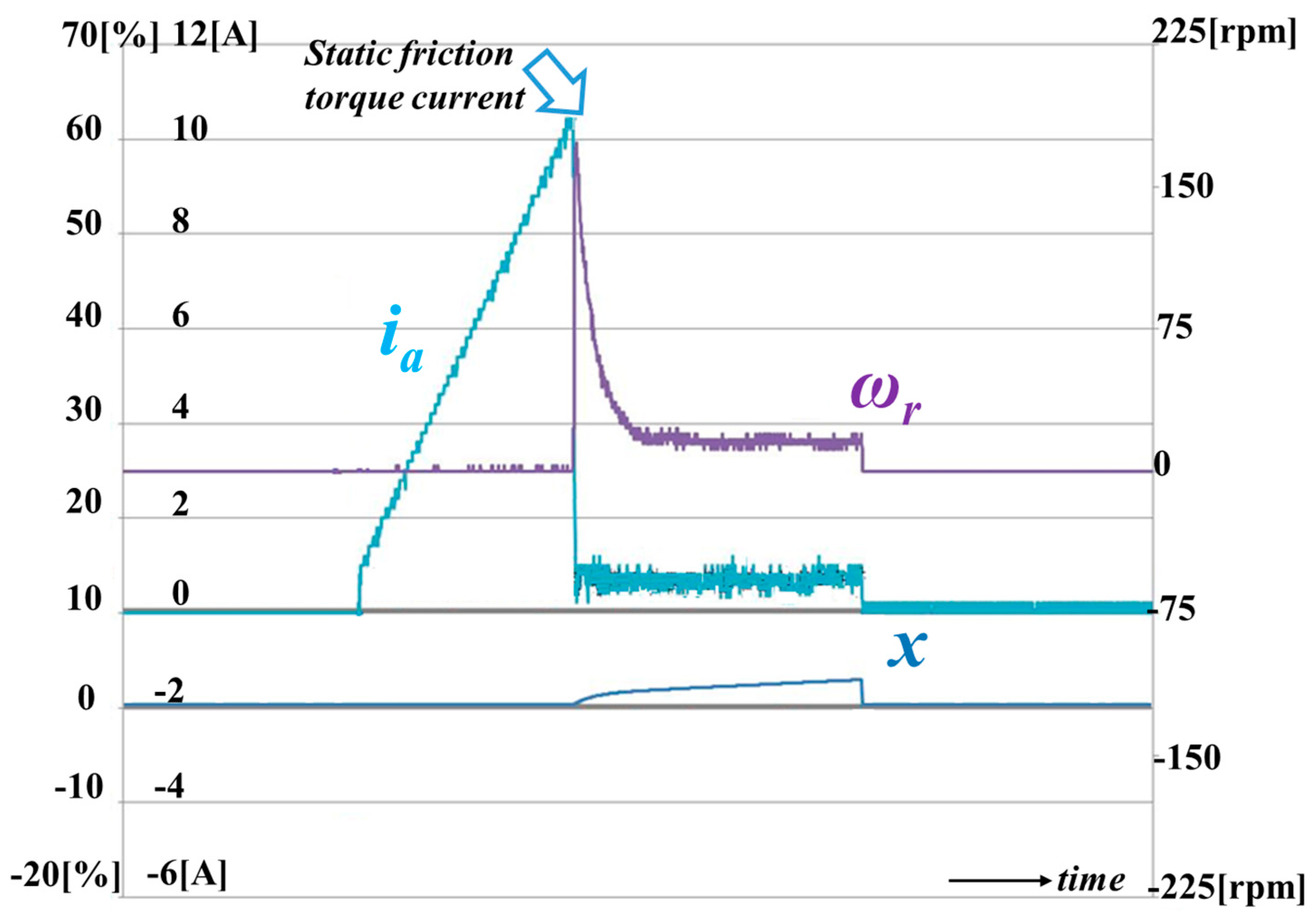
Figure 4 illustrates the measurement of the static friction torque. As shown in the figure, the current is increased to overcome the static friction force. However, the valve position does not move. If the current reaches the point described in the figure, the valve position starts to move due to the generated motor torque being greater than the static torque. At this time, speed increases radically when the static friction torque and the coulomb friction torque has a large difference. Note that the controlled speed is 20 rpm, which is the Stribeck velocity. In this case, the coulomb friction torque current is 0.8 A. However, the static friction torque is 10.4 A, which means that the static friction torque is over the 10 times that of the coulomb friction torque.
3. Proposed Position Controller
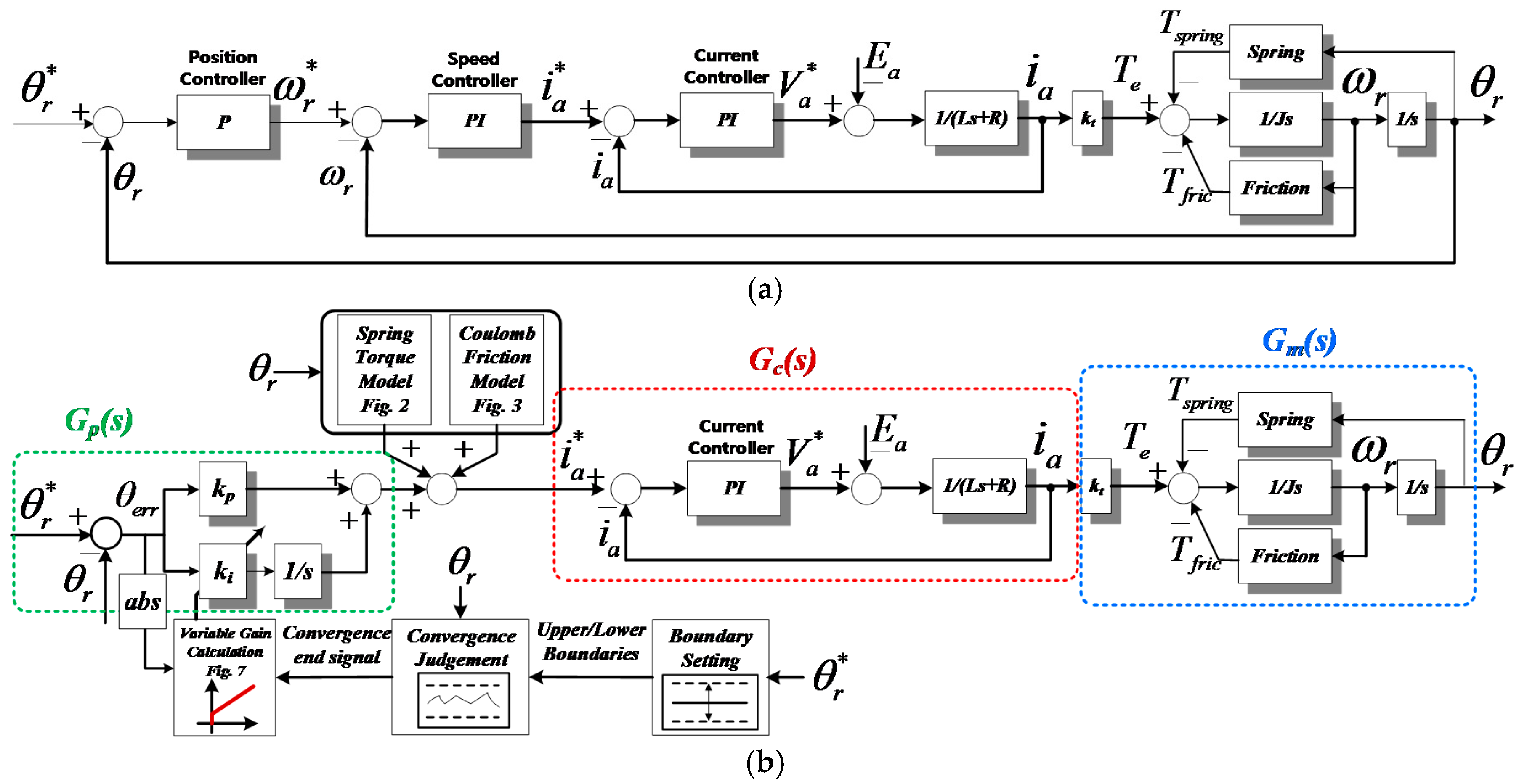
Figure 5 shows the conventional P-PI controller and the proposed control system [11]. As shown in the figure, the proposed control system does not use a speed controller. The main reason for this is that the motor position detection sensor is absent in the actual products to reduce the cost. Although the speed information can be obtained from the linear position sensor used for detecting the valve position, the sensing dynamics of the linear position sensor is insufficient to calculate the motor speed. Moreover, the speed information is the derivative component of the position information, so it is essential to use a filter to mitigate the noise. This worsens the restrictions on the bandwidth of the controller, which is already restricted due to the slow response of the linear position sensor.
For the same reason, the D controller cannot be used because the effective derivative component of the position error is difficult to obtain. Moreover, it can amplify the noise of the position information signal. Therefore, the PI controller was selected as the position controller in this system. Essentially, this position control system has performance problems.
First, proposed position control transfer function shown in Figure 5 can be described as:
The control dynamic of the current controller is much faster than the position controller. The transfer function of the current controller Gc(s) can be approximated as the unity in the position control view. Assuming that the spring load torque is fully compensated by the feedforward path, the transfer function can be changed to:
where km is kt/J.
Insert this transfer function into the final value theorem. The error of the step response can be obtained as:
From the above equation, the PI controller for position control has an error in the steady state. To solve this problem, the proposed control method was derived from the hysteresis control. The proposed control sets the allowable boundary to perceive that the practical position follows the reference. If the sensed linear position is inside the boundary, the timer is activated to observe that the controlled position is stably located in the boundary or it is just during a transient operation. In this paper, the time to perceive the controlled position to be in the steady state was 200 ms.
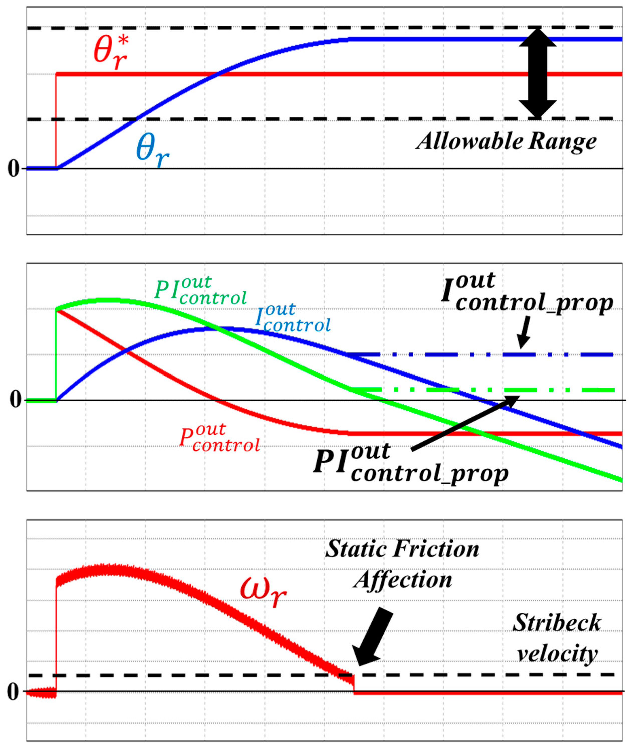
Figure 6 shows the problems experienced by the conventional PI controller. If the sensed position gradually reaches the reference position, the controller output is also reduced. It also reduces the generated current and the motor speed. In advance, if the speed is reduced below the Stribeck velocity, the static friction torque majorly affects the entire load torque. As a result, as indicated by the figure, the motor is stopped when the motor current does not overcome the static friction torque. Next, the I controller integrates the position error when the sensed position does not exactly follow the reference. This integrated error gradually increases or decreases the current reference. If the specific current value reached by the generated motor torque is above the static friction torque, it causes sudden speed variation shown in Figure 4, which creates the position vibration.
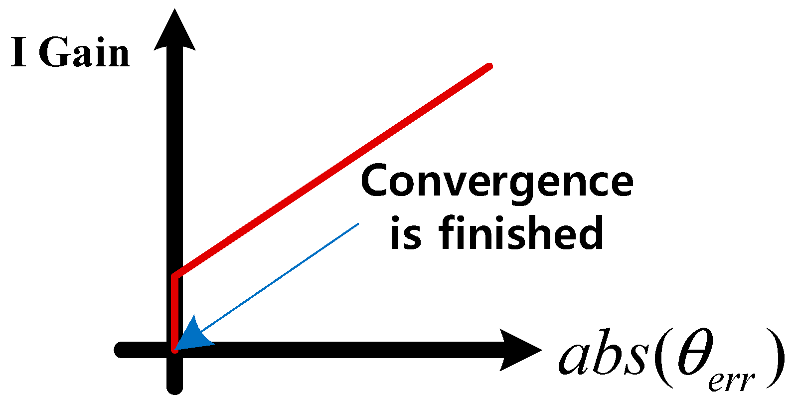
To solve this problem, the variable I controller gain was adopted according to the position error. When the position error reached the boundary, I controller gain was reduced to the minimum accordance with the position error, as shown in Figure 7. As mentioned above, the I controller is the root of the position control vibration, so this controller was inactivated, since the valve position was located inside the allowable range. In this case, only the P controller affects the current reference generation. As a result, position vibration did not occur with the proposed position control method. In this paper, this allowable range was 5% of the position reference.
4. Experimental Results
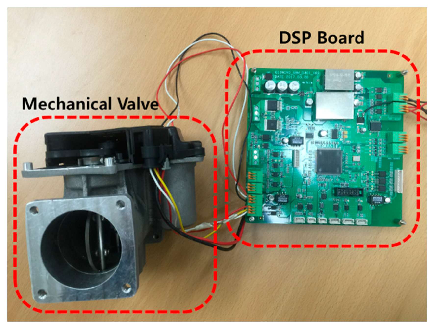
Figure 8 shows the experimental test setup. To compare our method with the conventional control method, a high performance DSP TMS320F28335 from TI was used. A speed sensor was also instantaneously implemented in the mechanical system. The sampling frequency of the current controller and the switching frequency were the same: 20 kHz. The position control frequency was 2 kHz. The motor parameters are shown in Table 1.
Figure 9 shows the position dynamic responses of 10% and 100% of the valve reference. Due to the high static friction torque, if the position error was small, the I controller needed some time to generate the output for the suitable torque against the static friction torque. Therefore, the gain had to be tuned considering the maximum allowable control response time when the smallest position reference was applied. As shown in the figure, when the 10% reference was applied, the control response time was much longer than the result obtained when the 100% reference was applied because of the static friction torque. This control gain cannot be increased infinitely because of the overshoot restriction. Therefore, control gain tuning involves a trade-off by considering two aspects: response time and overshoot.
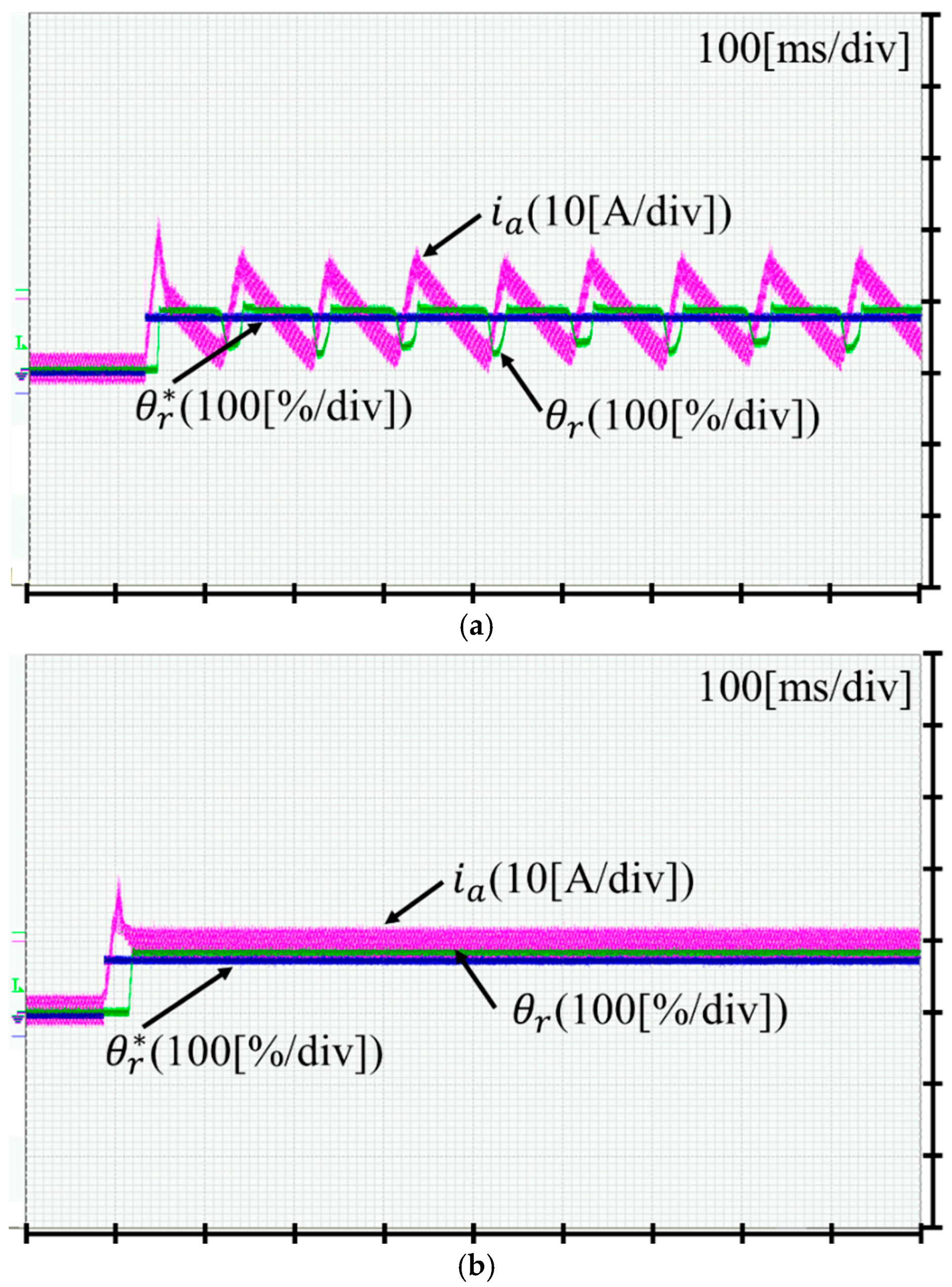
Figure 10 compares the experimental results obtained using both a conventional P-PI controller [11] and the proposed controller. As shown in the figure, the position controlled by the conventional method vibrated due to the large difference between static and coulomb friction torque. When the current reaches 2.5 A for the forward direction, the position movement is limited because the static friction torque resists the movement, however, since the current is above the 10 A, the position is radically moved forward because of the sudden friction change to coulomb friction torque. Due to the I controller affection, the current reaches to almost 17 A, and then, the position is over the reference. When the current reaches 17 A, the conventional controller starts to operate to move the position to the reverse direction. However, the position is almost stuck because of the high static friction torque, resulting in a slow decrease of the current to 2.5 A due to a small error integration of I controller. Subsequently, the controller starts to operate, and the position moves forward repeatedly. This operation caused the vibration as shown in Figure 10a. Note that the repeated current and the position are almost the same as shown in the figure, which meant that the static and coulomb friction torques at each position were hardly changed.
5. Conclusions
This paper proposed a position control method for a cost effective and a fast response time, which could be used in vehicle valve systems. Because the low-cost mechanical system has large differences in static friction and coulomb friction, the position and the current vibrations occur with the conventional P-PI linear controller. To solve this problem, this paper analyzed the EGR valve mechanical system and illustrated the procedure of extracting the parameters based on the predefined mathematical analysis. From this analysis, the proposed control method entailed acceptable boundary and selectable operation of the I controller. As a result, it could achieve the proper control performance which has an acceptable position error. The proposed method was verified by comparing our method with the conventional method in an experiment.
Author Contributions
J.-H.L. designed the experiment; J.-H.L. performed the experiment; J.-H.L. analyzed the theory. J.-H.L. wrote the manuscript. J.-H.L. and H.B. participated in research plan development and revised the manuscript. All authors have contributed to the manuscript.
Acknowledgments
This work is supported the Human Resources Development Program (Grant No. 20174010201350) by the Korea Institute of Energy Technology Evaluation and Planning (KETEP) grants. This research was supported by Korea Electric Power Corporation (Grant number: R18XA04).
Conflicts of Interest
The authors declare no conflict of interest.
References
- Murtaza, G.; Butt, Y.A.; Bhatti, A.I. Higher Order Sliding Mode Based Control Scheme for Air Path of Diesel Engine. In Proceedings of the 2016 International Conference on Emerging Technologies (ICET), Islamabad, Pakistan, 18–19 October 2016. [Google Scholar]
- Chen, S.K.; Yanakiev, O. Transient NOx Emission Reduction Using Exhaust Oxygen Concentration Based Control for a Diesel Engine; SAE Technical Paper No. 2005-01-0372; Ford Motor Company: Dearborn, MI, USA, 2005. [Google Scholar]
- Heywood, J.B. Internal, Combustion Engine Fundamentals; McGraw-Hill Book Co.: New York, NY, USA, 1998. [Google Scholar]
- Zheng, M.; Reader, G.T.; Hawley, J.G. Diesel engine exhaust gas recirculation—A review on advanced and novel concepts. Energy Convers. Manag. 2004, 45, 883–900. [Google Scholar] [CrossRef]
- Seo, E.-S.; Shin, H.-B. Modeling of EGR Valve Actuator. Trans. KIPE 2017, 22, 390–396. [Google Scholar]
- Kim, D.T.; Zhang, Z.J. Position Control of a Pneumatic Cylinder Considering Friction Compensation. J. Drive Control 2013, 10, 1–6. [Google Scholar] [CrossRef]
- Byun, J.H. A Study on the Position Control of a Motor Cylinder with Nonlineal Friction. J. Korean Soc. Power Syst. Eng. 2008, 12, 80–86. [Google Scholar]
- Chopra, S.; Mitra, R.; Kumar, V. Reduction of Fuzzy Rules and Membership Functions and Its Application to Fuzzy PI and PD Type Controllers. Int. J. Control Autom. Syst. 2006, 4, 438–447. [Google Scholar]
- Ni, Z.; Wang, M. Research on the fuzzy neural network PID control of load simulator based on friction torque compensation. In Proceedings of the Sixth International Conference on Intelligent Human-Machine Systems and Cybernetics, Hangzhou, China, 26–27 August 2014; pp. 292–295. [Google Scholar]
- Yao, J.; Deng, W.; Jiao, Z. Adaptive Control of Hydraulic Actuators with LuGre Model-Based Friction Compensation. IEEE Trans. Ind. Electron. 2015, 62, 6469–6477. [Google Scholar] [CrossRef]
- Kim, H.J.; Park, H.S.; Heo, H.J.; Kim, J.M. Improvement of Position Control Performance of EGR Valve System with Low Control Frequency. In Proceedings of the 2017 IEEE 3rd International Future Energy Electronics Conference and ECCE Asia (IFEEC 2017—ECCE Asia), Kaohsiung, Taiwan, 3–7 June 2017; pp. 394–399. [Google Scholar]
- Oh, B.G.; Lee, M.K.; Park, Y.S.; Lee, K.Y.; Sunwoo, M.H.; Nam, K.H.; Cho, S.H. Feedforward EGR Control of a Passenger Car Diesel Engine Equipped with a DC Motor Type EGR Valve. Trans. KSAE 2011, 19, 14–21. [Google Scholar]
- Lee, H.S.; Tomizuka, M. Robust Motion Controller Design for High Accuracy Position Systems. IEEE Trans. Ind. Electron. 1996, 43, 48–55. [Google Scholar]
Figure 1.
Mechanical composition of exhaust gas recirculation (EGR) valve.

Figure 2.
Measured spring torque.

Figure 3.
Measured friction torque.

Figure 4.
Static friction torque measurement at zero valve position (green: current, purple: speed, blue: position).
Figure 4.
Static friction torque measurement at zero valve position (green: current, purple: speed, blue: position).

Figure 5.
Position control method (a) P-PI controller [11] and the (b) proposed position controller.
Figure 5.
Position control method (a) P-PI controller [11] and the (b) proposed position controller.

Figure 6.
The operation of conventional and proposed PI controller.

Figure 7.
Variable I controller gain adaption according to the position error.

Figure 8.
Experiment setup.

Figure 9.
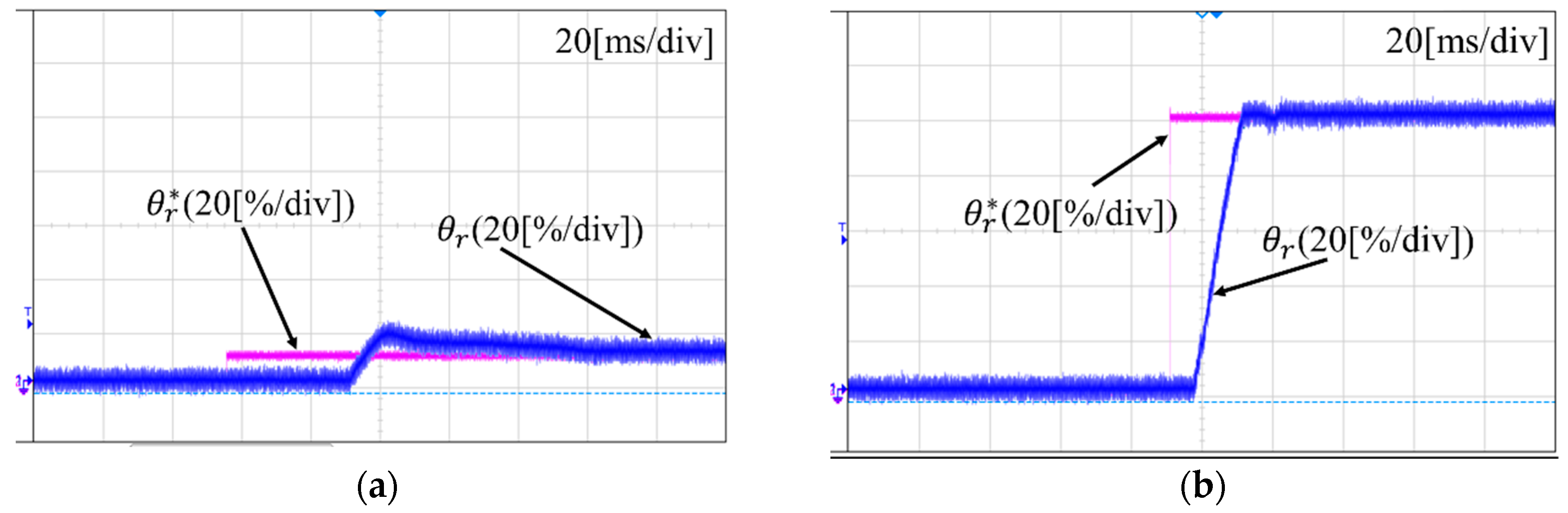
Position dynamic response when a (a) 10% and (b) 100% valve reference were applied.

Figure 10.
Comparison of the results between (a) conventional and (b) proposed position control (80% reference).
Figure 10.
Comparison of the results between (a) conventional and (b) proposed position control (80% reference).


Table 1.
Motor parameters.
| Parameter | Value | Unit |
|---|---|---|
| Rated power | 200 | W |
| Input voltage | 12 | V |
| Max. current | 20 | A |
| Rated speed | 500 | rpm |
© 2018 by the authors. Licensee MDPI, Basel, Switzerland. This article is an open access article distributed under the terms and conditions of the Creative Commons Attribution (CC BY) license (http://creativecommons.org/licenses/by/4.0/).
Share and Cite
MDPI and ACS Style
Bhuiyan, H.; Lee, J.-H. Low Cost Position Controller for Exhaust Gas Recirculation Valve System. Energies 2018, 11, 2171. https://doi.org/10.3390/en11082171
AMA Style
Bhuiyan H, Lee J-H. Low Cost Position Controller for Exhaust Gas Recirculation Valve System. Energies. 2018; 11(8):2171. https://doi.org/10.3390/en11082171
Chicago/Turabian StyleBhuiyan, Habib, and Jung-Hyo Lee. 2018. "Low Cost Position Controller for Exhaust Gas Recirculation Valve System" Energies 11, no. 8: 2171. https://doi.org/10.3390/en11082171
Note that from the first issue of 2016, this journal uses article numbers instead of page numbers. See further details here.