Research on a Plug-In Hybrid Electric Bus Energy Management Strategy Considering Drivability


1
Laboratory of Low Emission Vehicle, Beijing Institute of Technology, Beijing 100081, China
2
Qing Gong College, North China University of Science and Technology, Tangshan 063000, China
3
School of Mechanical Engineering, Beijing Institute of Technology, Beijing 100081, China
*
Author to whom correspondence should be addressed.
Energies 2018, 11(8), 2177; https://doi.org/10.3390/en11082177
Submission received: 25 July 2018
/
Revised: 10 August 2018
/
Accepted: 17 August 2018
/
Published: 20 August 2018
Abstract
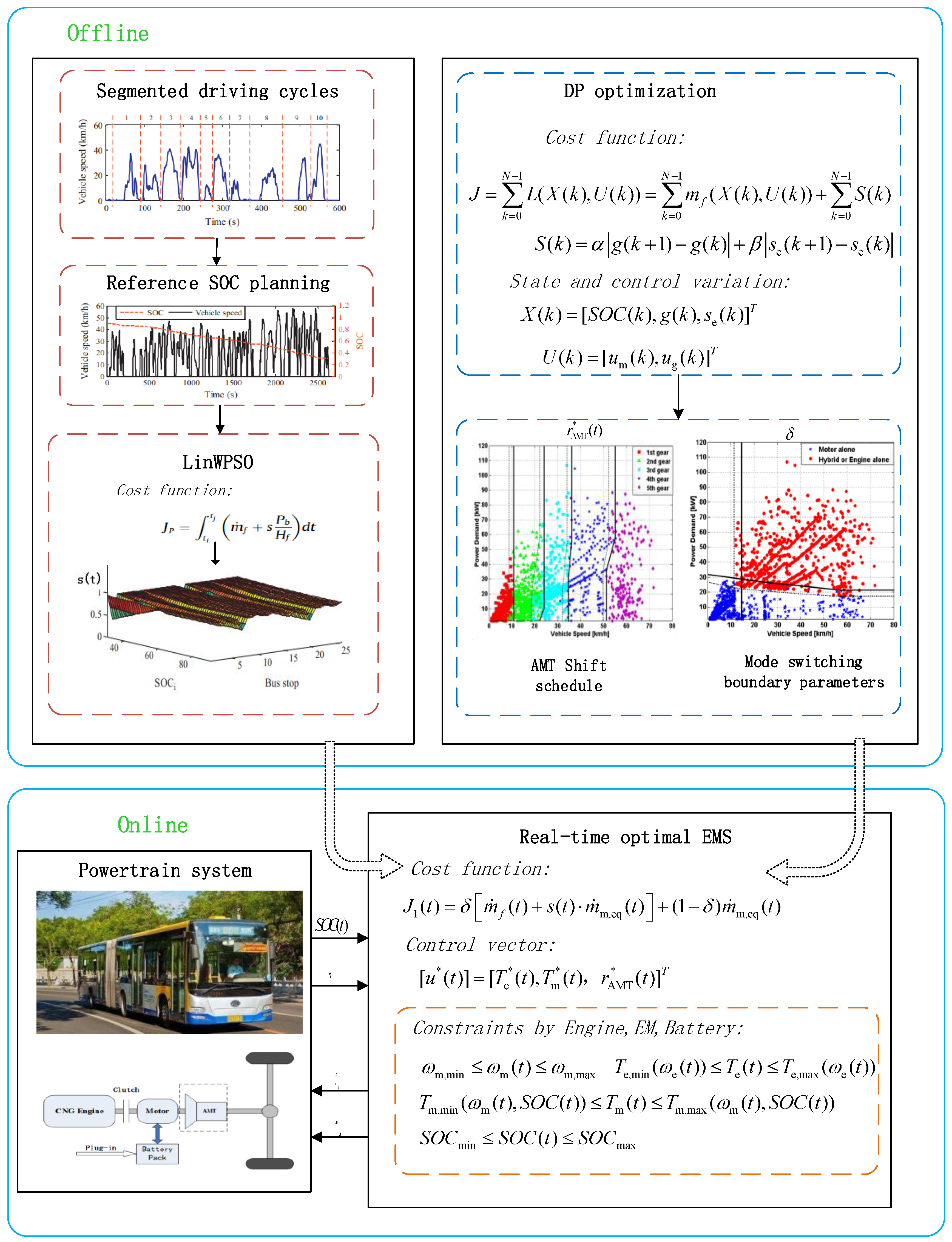
:Plug-in hybrid electric buses (PHEBs) is some of the most promising products to address air pollution and the energy crisis. Considering the switching between different working modes often bring about sudden changes of the torque and the speed of different power sources, which may lead to the instability of the power output and affect the driving performance and ride comfort, it is of great significance to develop a real-time optimal energy management strategy for PHEBs to achieve the optimization of fuel economy and drivability. In this study, the proposed strategy includes an offline part and an online part. In the offline part, firstly, the energy conversion coefficient s(t) is optimized by linear weight particle swarm optimization algorithm (LinWPSO), then, the optimization results of s(t) are converted into a 2-dimensional look-up table. Secondly, combined with three typical driving cycle conditions, the gear-shifting correction and mode switching boundary parameters that affect the drivability of the vehicle are extracted by dynamic programming (DP) algorithm. In the online part, combined with the s(t), the gear-shifting correction and mode switching boundary parameters which are obtained through offline optimization, the real-time energy management strategy is proposed to solve the trade-off problem between minimizing the fuel consumption and improving the drivability and riding comfort. Finally, the proposed strategy is verified with simulation, the results show that the proposed strategy can guarantee the engine and the electric motor (EM) work in the high-efficiency area with optimal energy distribution while keeping drivability in the variation of driving circle. The overall performance is improved by 18.54% compared with the rule-based control strategy. The proposed strategy may provide theoretical support for the optimal control of PHEB.
1. Introduction
In recent years, new energy vehicles have developed rapidly due to the demand for energy conservation and environmental protection. Plug-in hybrid electric vehicles (PHEVs) have attracted much attention due to their combination of the advantages of pure electric vehicles and fueled vehicles [1,2,3]. The powertrain of PHEVs is usually composed of motors, engines, and other power sources, which are coordinated to form a variety of working modes through the clutch or the planetary gear. Over the past few years, PHEVs with different configurations have been applied to various fields [4], whereas in the public transport areas, the single-shaft parallel configuration equipped with automated mechanical transmission (AMT) has become very popular owing to its compact architecture and efficient operating modes [5]. The performance of the PHEV is closely related to the energy management strategy (EMS). A reasonable EMS can allocate the power flow efficiently, give full play to the advantages of the engine and motor, and achieve the best performance of the vehicle.
Generally speaking, the EMS of PHEVs can be divided into two categories: the rule-based EMS and the optimization-based EMS. The rule-based strategies have shorter computation times and reliable application, and the rules can be set by drawing on practical engineering experience, with reference to engine optimal operating points and offline optimization strategy extraction [6]. The rule-based control strategies include deterministic rule-based methods and fuzzy logic rule-based methods [7]. For example, some researchers proposed a classical rule-based energy management strategy for PHEVs, which exhibited good reliability and stability in test driving cycles [8,9,10]. At the same time, many scholars have proposed fuzzy logic rules [11,12,13]. Although the rule-based EMS is easy to formulate, its rules need to be determined by a large number of experiments or practical calibrations. Once the working conditions change, it is necessary to set new rules, otherwise the fuel economy may get worse. Compared with the rule-based control strategy, the optimal control strategy can provide better energy allocation.
The optimization-based approaches can be further divided into global optimization and real-time optimization. As global optimization algorithms, dynamic programming (DP), particle swarm optimization (PSO) and genetic algorithm (GA), are widely applied in the solution process of the energy management problem of PHEVs [14,15]. Since the use of DP algorithm might be an effective way to design a theoretically global optimal EMS [16,17], a lot of studies on the DP-based strategy for PHEVs have been carried out. Peng [18] used the DP algorithm to optimize the fixed condition and obtained an improved control regulation. However, this method is only beneficial to the vehicles running on a fixed route. Once the route changes or the working conditions are unknown, it is not applicable. To solve the above problem, references [19,20,21] employed a driving pattern recognition technique of switching among the control rule sets extracted from DP results of each representative driving pattern, and the generality of the rules was realized. Besides, considering the time consuming of DP, it is difficult for a DP-based algorithm to be realized in practice from an engineering perspective. Chen [22] used quadratic programming and simulated annealing method together to obtain the optimal result. Compared with the DP algorithm, computation time was saved without affecting the calculation accuracy. In [23,24], a novel pseudo-spectral power management algorithm was presented, and the results showed that this algorithm was numerically more efficient than DP and was able to achieve a solution very close to that of DP.
For real-time optimization control, the equivalent consumption minimization strategy (ECMS) and model predictive control (MPC) are the two most representative methods. On the basis of real-time information provided by historical driving data, mathematical models or intelligent transportation systems, MPC can predict the torque requirements of vehicles and optimize the energy allocation ratio to achieve low fuel consumption and emission [25,26]. However, the MPC control effect depends on the future driving information prediction accuracy, which remained to be an open question for now [27,28,29]. Based on Pontryagin’s minimum principle, the ECMS simplifies the dynamic optimization problem into an equivalent instantaneous optimization problem, which reduces the computational complexity of the optimal algorithm and is suitable for real-time controllers. In ECMS, energy conversion coefficient, i.e., s(t) is a key dynamic variable, which determines the real-time performance [30]. In order to obtain accurate s(t), many scholars have presented improved methods. Reference [31] obtained s(t) by predicting the future road speed, but this method needs a lot of accurate prediction. Kessels [32] used fuzzy control-based ECMS to deal with the complex relation between fuel economy and the state of charge (SOC). However, the s(t) accuracy of this method depends on the knowledge and experience of the expert. In [33,34], feedback control was used to adjust the s(t). However, due to the discharge characteristics of large capacity batteries, this method cannot be directly applied to PHEBs. Based on these valuable research works, using optimization methods may be a fruitful direction in ECMS to obtain an optimized s(t).
However, the EMS mentioned above mainly concentrate on the fuel economy and the emissions without considering the drivability and the ride comfort. For the PHEB, the switching between different working modes often brings a sudden change of the torque and the speed of different power sources, which leads to the instability of the power output and affects the driving performance and ride comfort. At the same time, the frequent gear-shifting will also affect the drivability of vehicles. Therefore, it is worthwhile to study the improvement of the drivability and ride comfort on the premise of ensuring fuel economy. In [35,36], an insightful method that simultaneously optimizes the power split and the gear-shifting is proposed. However, due to the closely interactive relationship between power split and gear-shifting, it would break the optimal decisions and worsen the vehicle fuel economy considerably if any changes happen to the optimal gear-shifting to obtain good drivability. Moreover, the simultaneous optimization would highly increase the calculation burden [37]. Therefore, it is necessary to decouple the gear-shifting logic from the whole optimization.
In this paper, considering the improvement of the drivability and economic performance of the PHEB, a real-time EMS is proposed. The proposed strategy includes an offline part and an online part. The offline optimization consists of two parts: the first part is to obtain the energy conversion factor s(t). First, the driving cycles are divided into segments based on actual bus stops, then the s(t) of each segment is optimized by linear weight particle swarm optimization algorithm (LinWPSO). The optimization results of s(t) can be used to make real-time adjustments to online control strategy. The second part is that the corresponding control parameters that affect the vehicle drivability and riding comfort are extracted by DP algorithm, which includes AMT gear-shifting strategy and mode switching boundary parameters. In the online part, combining with the s(t), AMT gear-shifting correction and mode switching boundary parameters which are obtained through offline optimization, the real-time EMS is proposed to solve the trade-off problem between minimizing the fuel consumption and improving the drivability and ride comfort.
The organization of this paper is as follows: Section 2 illustrates the compositions and mathematical models of the plug-in hybrid powertrain. Section 3 describes the problem formulation and the optimal strategy. The AMT gear-shifting correction and mode switching boundary parameters are extracted in Section 4. Then, the optimization results and the comprehensive performance analysis are presented in Section 5. The conclusions are presented in Section 6.
2. Configuration of the Power Drive System and the PHEB Control Method
2.1. Configuration of the Power System and Work Mode
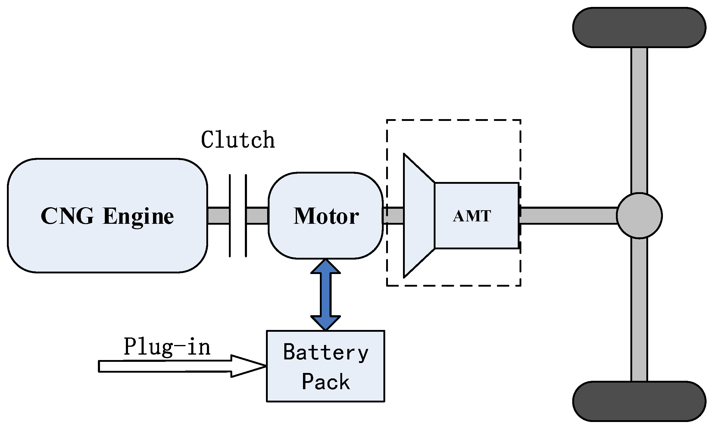
The schematic of the single-shaft parallel hybrid configuration with AMT is shown in Figure 1. In this configuration, the engine and the electric motor (EM) can drive the vehicle separately or together, and it also has the function of braking energy recovery. The fundamental parameters of the target vehicle researched in this paper are shown in Table 1.
As shown in Figure 1, the hybrid system has five typical operating modes: pure electric mode, engine driving mode, hybrid driving mode, driving charging mode, and braking energy recovery mode. In actual operation, with the appropriate energy management strategy, the hybrid system switches among these modes according to different torque requirements to improve the energy economy. In the following subsection, the quasi-static models of components are established.
2.2. System Models
2.2.1. Vehicle Longitudinal Dynamics
According to the vehicle longitudinal dynamics equation, the traction acting on the wheel can be written as:
where Fi, Fro, Fl and Fst are the acceleration resistance term, the rolling resistance term, the aerodynamic drag force term, and the gradient resistance term, respectively. Their expressions are shown as follows:
where m is the vehicle mass, g is the gravity acceleration, fr1 and fr2 are the rolling resistance coefficient, ρa is the air density, CD is the aerodynamic drag coefficient, Af is the bus frontal areas, α is the road angle, vrv is the vehicle speed.
According to (1)–(5), the vehicle’s main reducer demand torque could be obtained as follows:
where rwh is the wheel radius, Jwh is the wheel moment of inertia, Twh,loss is the wheel torque loss, is the wheel acceleration.
2.2.2. Transmission System Model
The transmission system model includes the gearbox model and the main reducer model. The gearbox plays an important role in the powertrain, changing the gear ratio to meet the traction requirements of the vehicle under different driving conditions. The main reducer is used to transmit the torque and the speed of the gearbox to the driving wheels. The structure of the main reducer is similar to that of the gearbox, but it has only one transmission ratio. The relationship between angular velocity at the input of the gearbox and the can be calculated by:
At the same time, the demand torque of the gearbox Tgb could be obtained as follows:
where ηgb is the efficiency of transmission system, igb is the total ratio of transmission system.
2.2.3. Engine Model
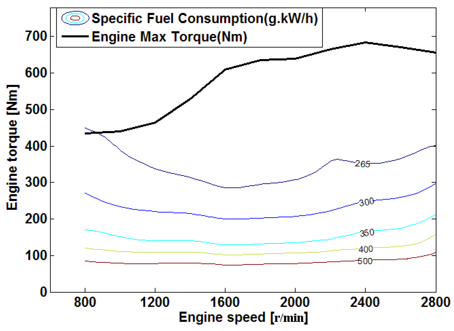
There are many kinds of engine modeling methods, which mainly include experimental modeling and theoretical modeling. In theoretical modeling methods, it is difficult to apply to the optimization algorithm, because the model is complex, the calculation time is long, and the parameters that need to be identified are numerous. Therefore, the steady-state model of a CNG engine is adopted in this paper, the fuel consumption at each moment can be obtained by checking the fuel consumption MAP of the engine:
where ωe is the speed of engine, ρ is the density of CNG, be is the fuel consumption rate. The be could be obtained by look-up table according to Te and ωe at any given time, the fuel consumption contour map is shown in Figure 2.
2.2.4. EM Model
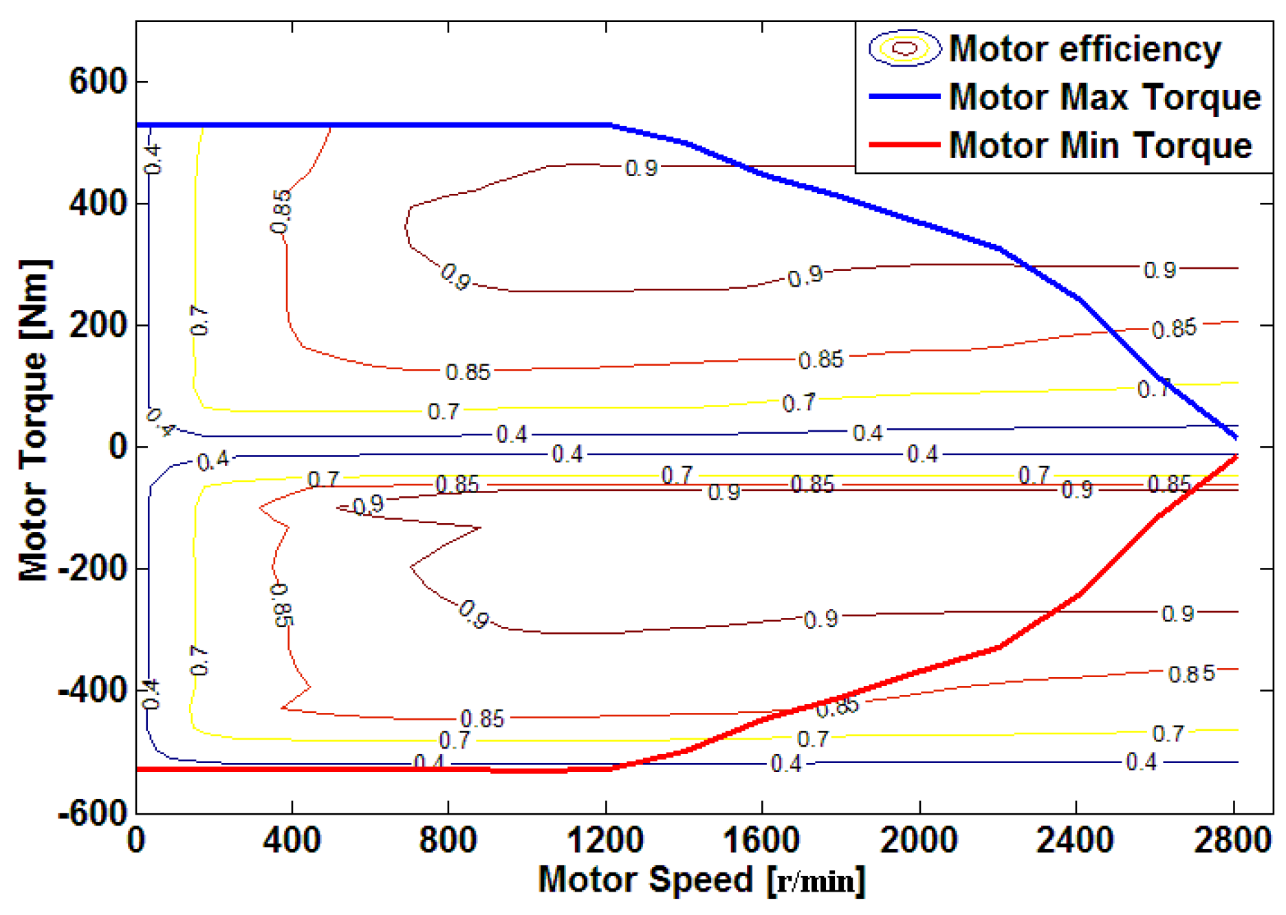
This paper chooses permanent magnet synchronous motor, which can work as a traction motor and a generator inthe driving process and the braking process, respectively. The EM model is built using experimental data as well as the engine model.
When the EM is used as a traction motor, the EM power Pm can be calculated by Equation (10) and when the EM is used as a generator, Pm can be calculated by Equation (11):
where ωm is the speed of EM. ηm and ηg are the efficiency when the EM is used as the motor and the generator, respectively. ηm and ηg could be obtained through look-up table, and the EM efficiency diagram is shown in Figure 3.
2.2.5. Battery Model
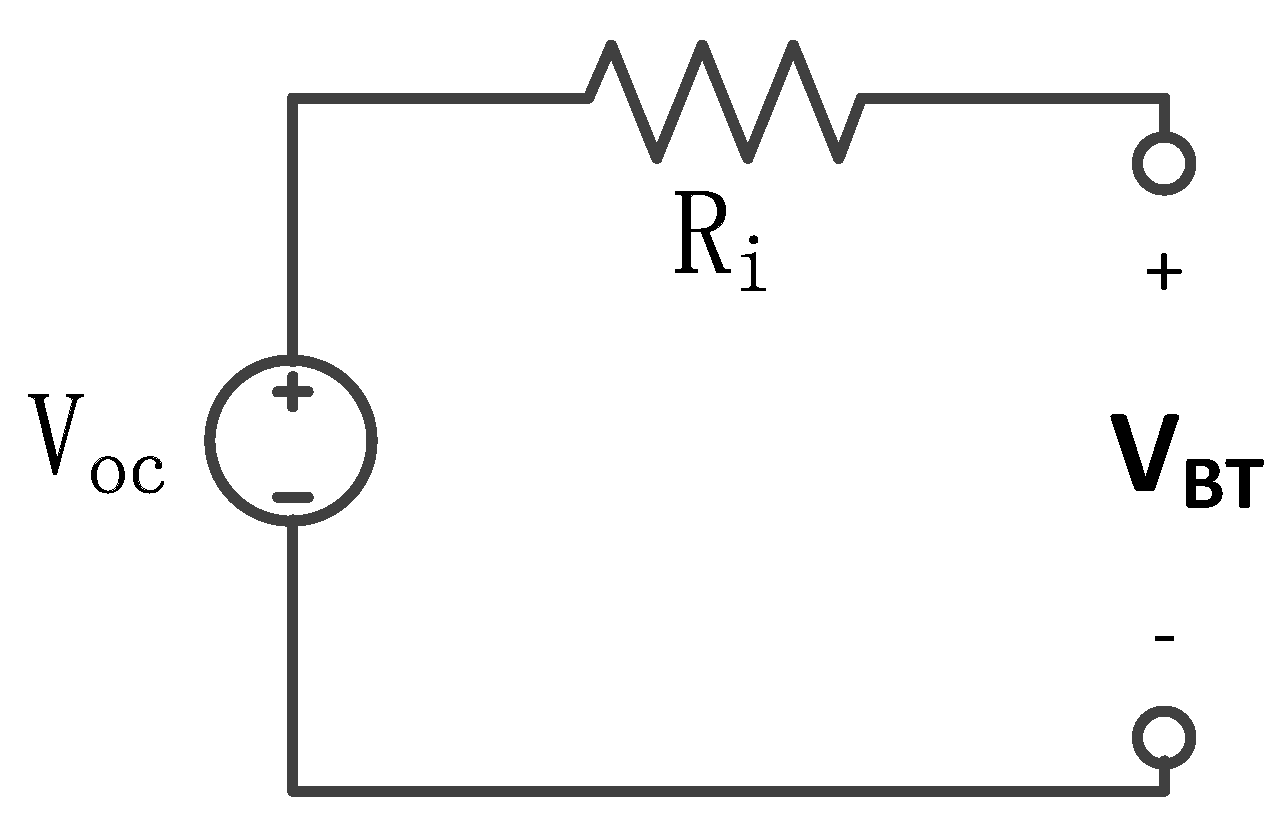
For simplicity, the battery is assumed to operate at aconstant temperature and is modeled by the Rint model [14,15], as shown in Figure 4.
According to Ohm’s law, the output load voltage is expressed as:
where IBT is current of battery, Voc (SOC) and Ri (SOC, sign (IBT)) are the open circuit voltage and the internal resistance of the battery, respectively, which are all related to SOC. The relationships between battery SOC and open circuit voltage are fitted according to the experimental results, as shown in Figure 5.
According to the Equation (12), the battery output power PBT could be obtained as follows:
By simple circuit analysis and calculation, the output current of battery IBT could be obtained as follows:
Then, the state equation of SOC can be calculated by:
where SOC(k) is the SOC of the battery at the time k, Q0 is the capacity of the battery.
3. The Energy Management Optimization for REEBs
PHEB energy management strategy is the core function of the vehicle controller, which has a great impact on vehicle performance. For the single axis parallel hybrid city bus with AMT, the frequent gear-shifting and mode switching process will be accompanied by power interruptions, which affects the riding comfort and driving stability. Therefore, it is necessary to consider the drivability of the vehicle. To improve this situation, a novel algorithm is brought forward to improve the fuel economy and the drivability of the PHEB in any given city-bus driving cycle. The diagram of the algorithm is shown in Figure 6. As shown in Figure 6, the proposed strategy includes two parts, i.e., the offline part and the online part.
To clearly show the proposed strategy, the detailed procedure can be divided into three parts. Part one: s(t) is obtained through offline optimization. First, the driving cycles are divided into segments according to the actual positions of the bus stops. Then, the s(t) of each segment is optimized by LinWPSO. Last, the optimization results of s(t) are converted into a 2-dimensional look-up table, which can be used to make real-time adjustments to online control strategy. Part two: the AMT gear-shifting correction and mode switching boundary parameters that have obvious influence on the drivability of the vehicle are obtained by an offline DP algorithm. Part three: combined with the parameters of offline optimization, a real-time optimal EMS can be developed to solve the instantaneous optimization problem for the studied PHEB. Finally, the proposed strategy was verified in a real-world driving cycle in simulation.
3.1. Real-Time Optimal Energy Management Strategy
The ECMSis used more in the PHEV energy management strategy. It makes the electrical consumption of the motor equivalent to fuel consumption, and it also makes the overall equivalent fuel consumption of each moment of the system minimum to achieve local optimal. The ECMS-based PHEV energy management strategy can be described like this: at a certain time t, there is an optimal control vector , which minimizes the system cost function JECMS(t) at this moment. Their expressions are shown as follows:
where is the engine fuel consumption rate, s(t) is the energy conversion coefficient, which canbe attained by the following offline optimization. is the equivalent fuel consumption rate of the motor, is the control variable.
The standard ECMS only considers the energy distribution. However, while concerning the energy distribution, this paper also considers the driving performance of the vehicle. Therefore, based on ECMC, this paper proposes a new real-time management strategy. The optimal control problem is to find the control input to minimize the following cost function:
where δ is the mode switching boundary parameters, which can be attained by the next offline optimization. When δ = 1 the engine and EM work together to drive the vehicle, when δ = 0, the EM drives the vehicle alone.
The EM equivalent fuel consumption rate can be obtained:
where Qlhv is the low calorific value of fuel, ηm,req(Tm,req(t), ωm(t)) is the EM efficiency, Tm,req(t) the EM demand torque, ωm(t) is the EM speed.
For a single-axis parallel PHEB, when the clutch is closed, the engine speed is equal to the motor speed, so the energy distribution ratio is replaced by the torque distribution ratio. The best control vector is shown as follows:
where is the engine torque, is the EM torque, is the AMT gear-shifting rules, which can be attained by the following offline optimization.
Considering the actual operating performance of the PHEB, the operating state of the engine, EM and battery should be limited by the following constraints:
where ωm,min, ωm,max are the EM speed lower limit and upper limit, Te,min(ωe(t)), Te,max(ωe(t)) are the engine torque lower limit and upper limit, Tm,min(ωe(t),SOC(t)), Tm,max(ωe(t),SOC(t)) are the EM torque lower limit and upper limit, SOCmin, SOCmax are the battery SOC lower limit and upper limit. rATM(t) is the gear of the AMT, rATM,min, rATM,max are the maximum gear and minimum gear.
3.2. s(t) Optimization
In order to get better economic performance with the ECMS control strategy, the choice of s(t) is especially critical. If the value of s(t) is large, the engine fuel consumption will increase. On the contrary, the power consumption will increase and the battery SOC will drop at a faster rate. Moreover, the s(t) should not be set to a static coefficient or a fixed value, which will affect the performance of the vehicle. Therefore, it is necessary to optimize s(t) in the real time according to the information of vehicle driving conditions and battery SOC.
As repeated operations on the same routine route are characteristic of urban buses, the total daily running mileage of the vehicle is known, and the distance between the vehicle stops is also fixed, so the equivalent coefficient s(t) can be optimized under known conditions. Yang [38] provided a new method to optimize s(t), which has achieved good results. The specific implementation process is shown in the Figure 7. There are in total four steps.
In step 1, the driving conditions were divided into several parts based on actual bus stations, then, the bus station and the vehicle speed are selected as input variables for subsequent optimization.
In step 2, historical data collected from different parts are used to design the reference SOC. Therefore, the reference SOCr can be obtained as follows:
where SOCi is the initial SOC of the battery, SOCl is the minimum value of the battery SOC, n is the number of the bus station, j is the total number of the bus stations, fi is the coefficient of SOC changing rate, li is the distance between stations, D is the driving distance of the vehicle, is the average demand torque.
In step 3, based on the reference SOC, the s(t) of each part is optimized by LinWPSO. For LinWPSO, the inertia weight factor can be written as:
where T, Tmax are the current iteration number and the maximum iteration number, respectively. Xmax is the initial weight factor, Xmin is the final weight factor.
The objective function JP can be shown in the following equation:
where ti, tj are the start and end time, respectively. Pb is the power of the battery, Hf is the low heat value of the gas, s is the energy conversion coefficient.
Then, the s(t) can be obtained as:
where si is the initial s(t), k is the coordination variable, SOCn is the current SOC.
In step 4, the s(t) of each part can be displayed in the form of the 2-dimensional look-up tables. For the specific calculation process, please refer to [37].
4. Dynamic Programming
4.1. Problem Formulation
In the application of the DP algorithm, the discrete-time form of the system state-space model canbe expressed as follows:
where X(k) is the state variable, U(k) is the control variable.
In order to constrain the parameters that affect the drivability of the vehicle, such as AMT gear-shifting correction and mode switching boundary parameters, namely, frequent gear-shifting and frequent engine start-stop, the engine start-stop state variables Se(k) and the gearbox state variables g(k + 1) are set as follows:
where g(k + 1) is the current gear number, the value of the gear-shifting signal ug(k) could be −1, 0 and 1, which represent downshifting, sustainability, and upshifting, respectively, so the ug(k) can be written as:
Based on the above analysis, taking the engine start-stop and AMT gear-shifting into account, the state vector X(k) and the control vector U(k) of the system are described as follows:
where um(k) is the ratio of the EM torque to the input torque of the gearbox.
The optimal control problem is to find the control input U(k) to minimize the following cost function:
where N is the time of the drive cycle. L is the instantaneous cost at phase = k. S(k) is the penalty function for gear-shifting and engine start-stop, which can be expressed as:
where α is gearbox gear-shifting penalty factor, β is engine start-stop penalty factor.
The value of penalty factor are α = 2.5, β = 1, which are obtained through multiple simulation calculations. As Equation (28) shows, the cost function consists of two parts, namely, the CNG consumption of the engine and the drivability of the vehicle. In the optimization process, to ensure that the components work within a reasonable range, the operating state of the engine, motor, battery and transmission must be constrained. The specific constraints are as the same as in Equation (21).
4.2. Parameter Extraction
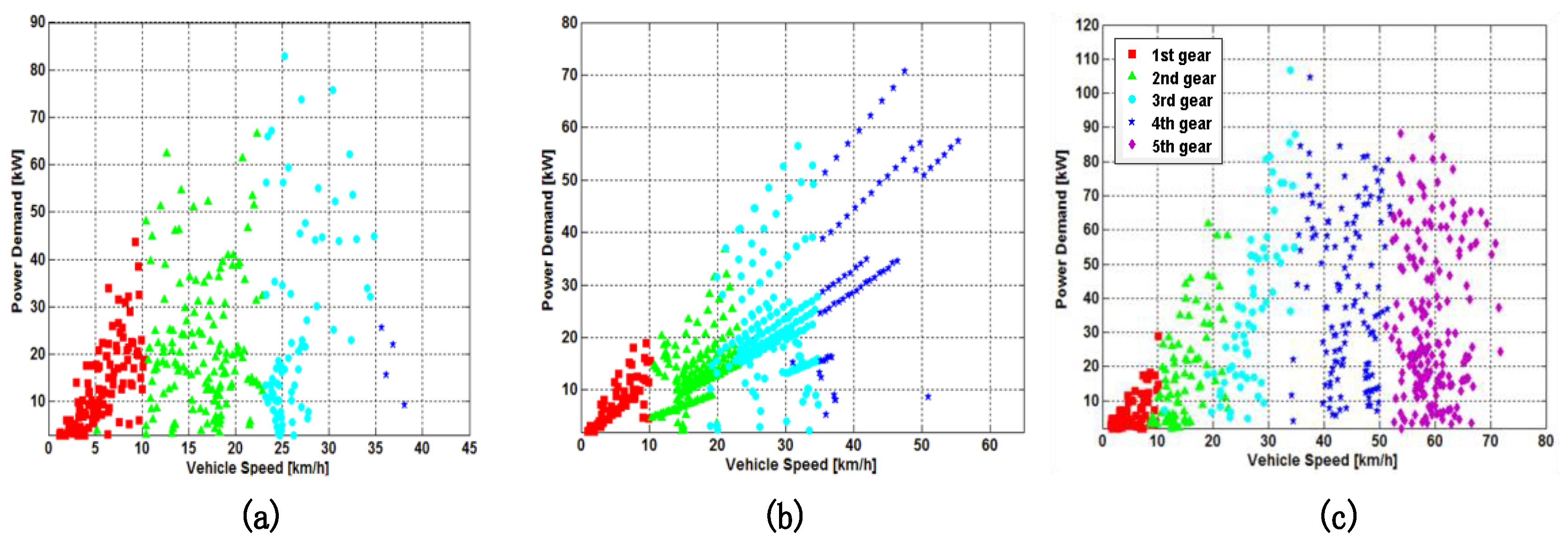
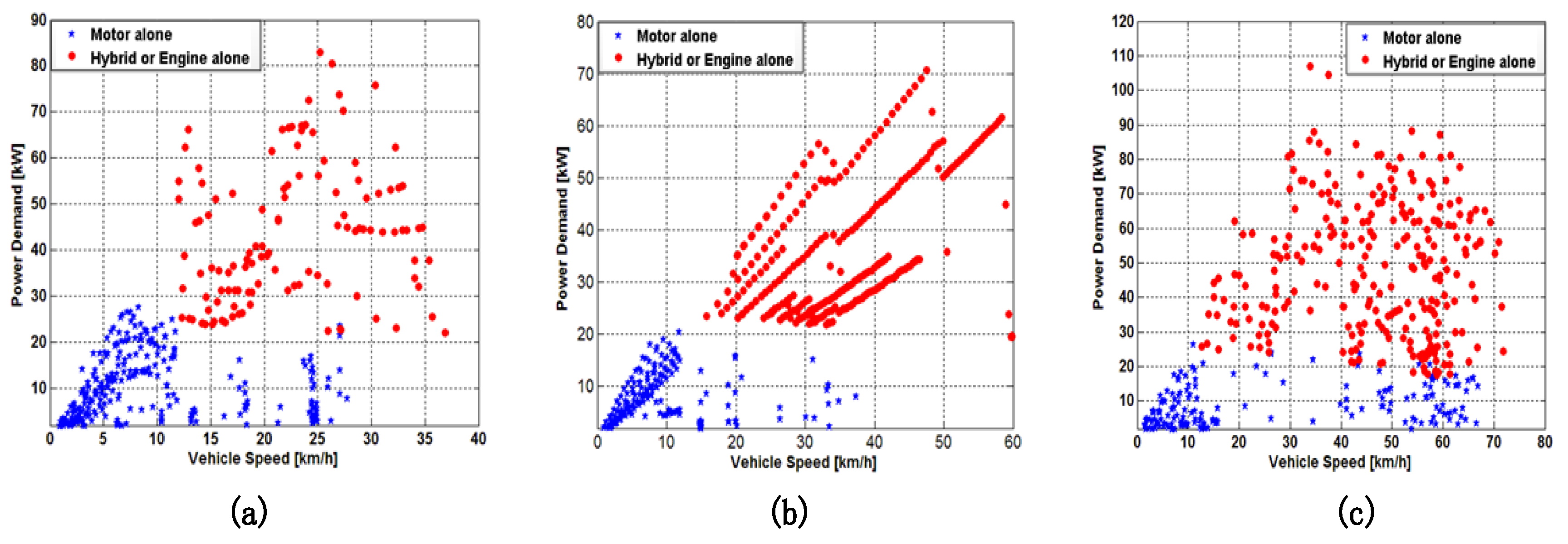
The optimization results of the DP algorithm are sensitive to the driving conditions. It is difficult to reflect the actual driving situation of the city bus in a single driving cycle. Therefore, three typical driving cycle conditions are introduced: China typical urban bus driving cycle, Manhattan bus drive cycle (CYC_MANHATTAN), and West Virginia suburban driving schedule (WVUSUB). The corresponding AMT gear-shifting correction and mode switching boundary parameters are shown in Figure 8 and Figure 9.
As shown in Figure 8 and Figure 9, the gear position and mode switching boundary conditions optimized by the DP are not only related to the vehicle speed, but also related to the vehicle energy demand. The combination of simulations of multiple driving cycle conditions can be as close as possible to the actual driving conditions and achieve the simulation effect under full working conditions.
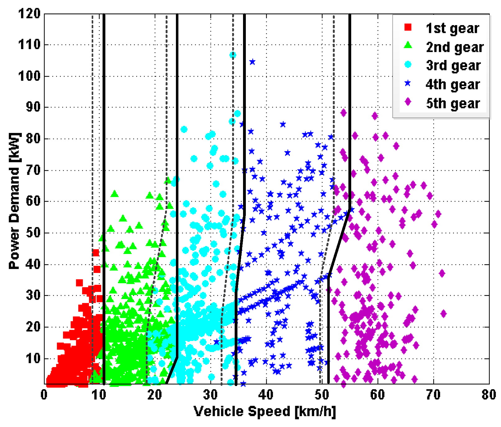
Since the driving cycle time is longer during the simulation process, the data in the Figure 8 and Figure 9 do not represent all the gearspoints and mode switching boundary parameters, but the data obtained by extracting certain samples from the overall data. In order to extract the gear-shifting correction and the mode switching parameters conveniently, which are shown in Figure 10 and Figure 11, separately, the data optimized by the three working conditions are superimposed and displayed in the same picture, As shown in Figure 10, the solid black line represents the upshift line, and the black dotted line represents the downshift line. As shown in Figure 11, the black solid line is the boundary line representing the pure electric mode switching to the engine participating mode, and the black dashed line represents the reverse switching boundary line.
5. Verification and Discussion
Through the off-line optimization, the parameters that affect the vehicle’s economic performance and the drivability are obtained. These parameters are combined together to form the PHEV real-time optimization energy management strategy.
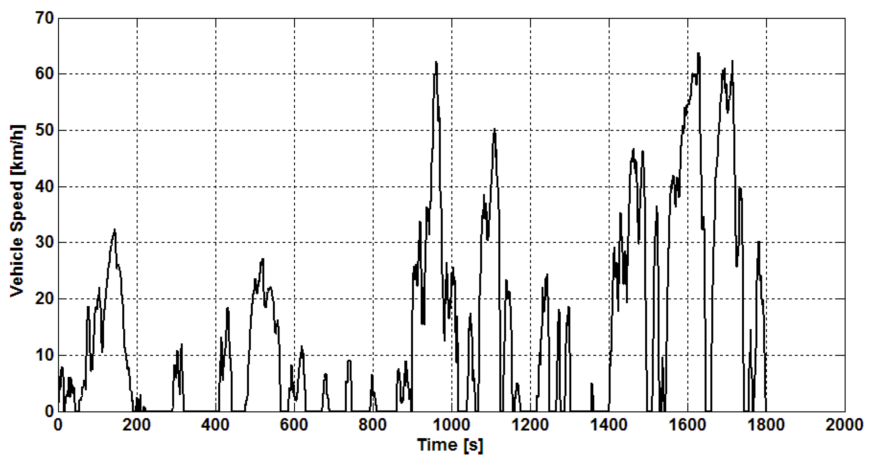
In this section, the proposed EMS is verified by a simulation. To verify the proposed strategy, the Beijing typical city bus driving cycle is chosen as the test driving cycle, as shown in Figure 12. This working condition is extracted from the actual driving conditions of several Beijing buses. The mileage of a single driving cycle is 6.81 km, with 10 stops, 21 acceleration sections and 10 traffic lights. According to the vehicle’s full-day driving range of 200 km, an average of 30 selected driving cycles are required for one day. Therefore, in the simulation, 30 driving cycles were taken as input conditions. Table 2 shows the statistics of Beijing typical citybus driving cycle.
In order to show the advantages of the proposed strategy, the control performance, the fuel consumption and the comparison result of the drivability with different strategies are given in the following part, in which the effectiveness, the fuel economy improvement, and the drivability are verified.
5.1. Control Performance of Proposed Control Strategy
To verify the control performance of the proposed strategy, the simulation works are carried out under Beijing typical city bus driving cycle. The initial SOC is set as 100%, and the terminal SOC is set as 30%. The results are shown in Figure 13, Figure 14 and Figure 15.
Figure 13 show the basic simulation results, including battery SOC of hybrid powertrain, engine output power, and EM output power, which can reflect the control performance of the proposed strategy. It can be seen from Figure 13 that SOC has decreased steadily during the entire mileage and remains at 0.3 by the end of the journey. When the SOC is higher, the motor’s braking energy recovery is less, and when the SOC is lower, the motor’s braking energy recovery is more.
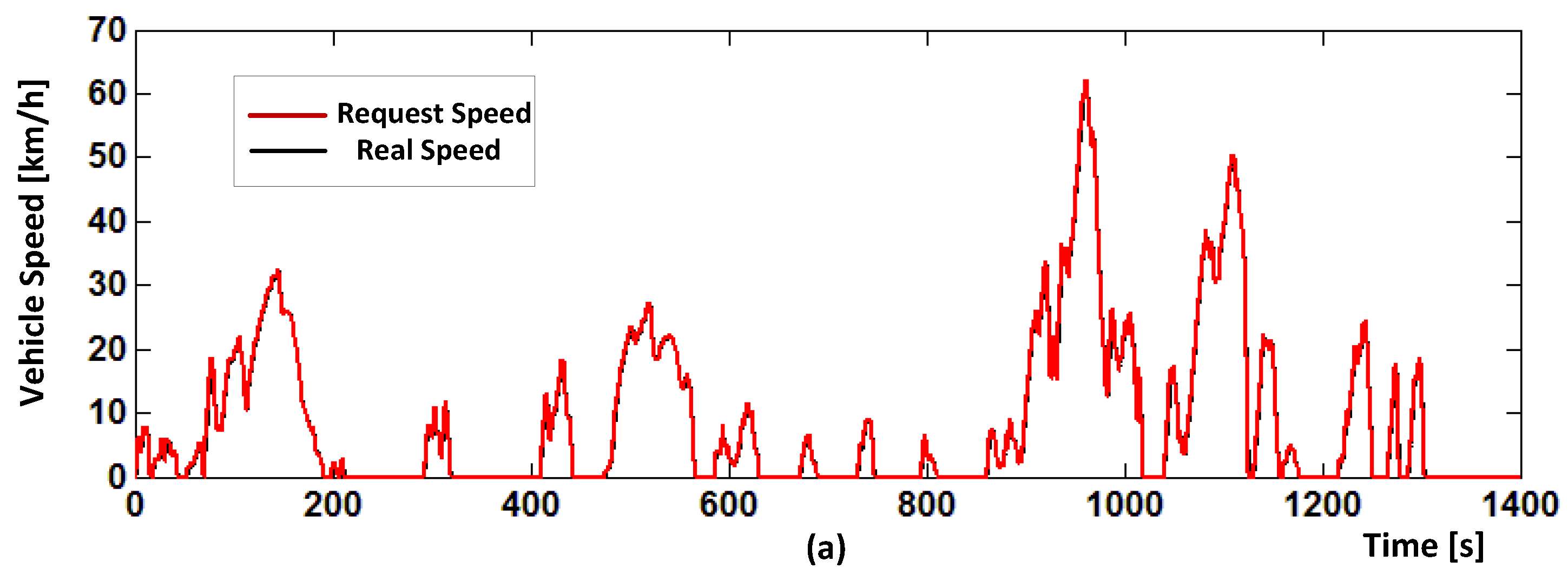
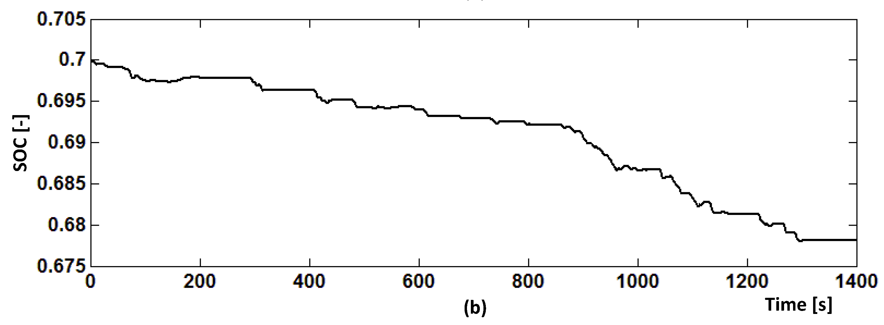
Since the overall operating data is too large, it is not suitable for observation, so the condition that the battery SOC is 0.7 is utilized for our explanation. As shown in Figure 14, the simulated vehicle speed is the same as the actual vehicle speed. In addition, the battery SOC continues to decrease with the operation conditions, the SOC of the initial state is 0.7, and the SOC of the terminal state is 0.678, which conform to the trend of the energy consumption.
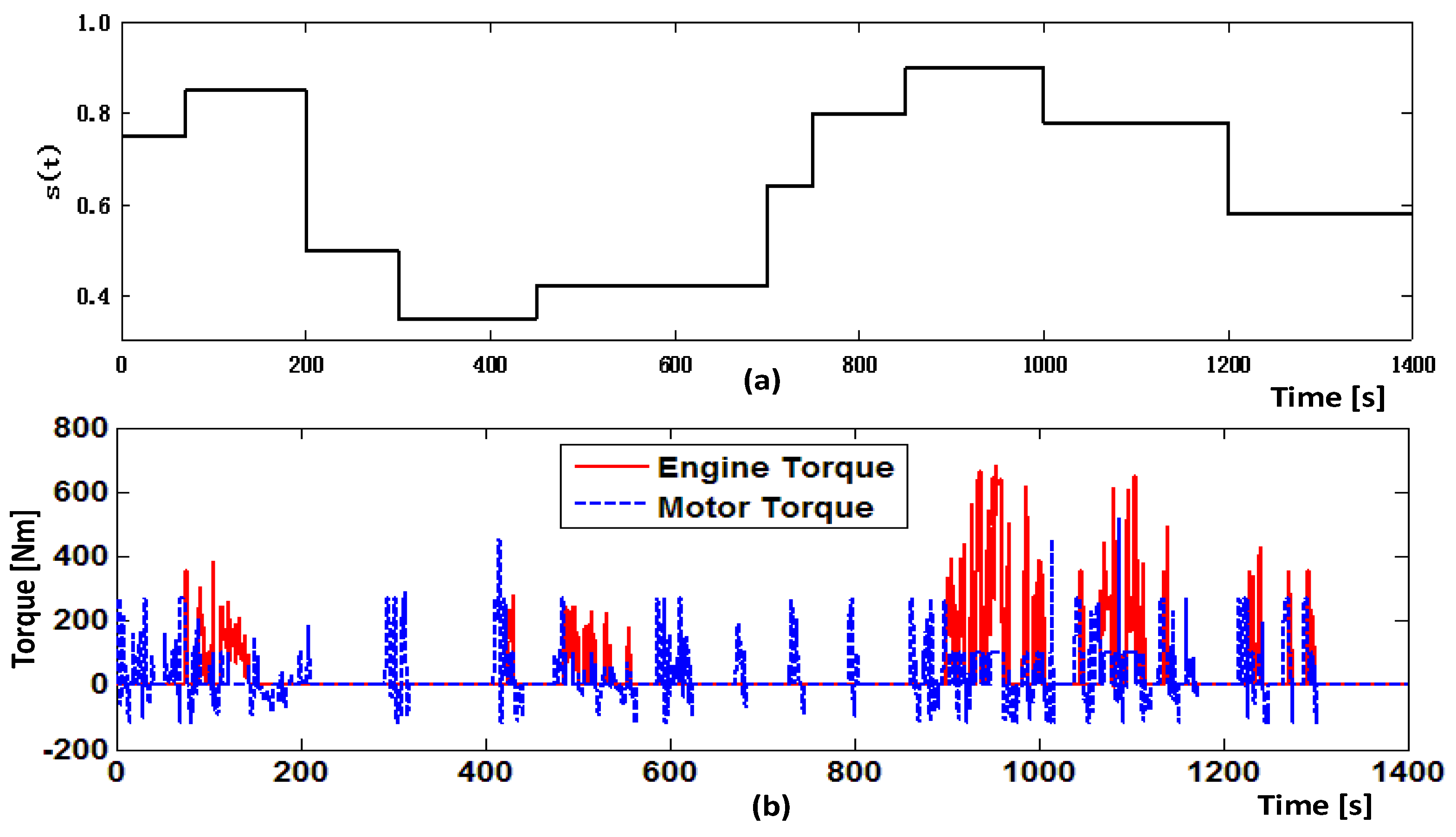
As shown in Figure 15a, the s(t) adopted in the proposed method would change with the variation of the driving condition along the whole bus routine. Under the selected driving cycle conditions, the EM and engine torque are shown in Figure 15b, the output torque of engine and EM could satisfy the demand torque of hybrid powertrain to ensure the drivability of PHEB. To avoid the low-efficiency working area of engine, the EM is controlled to drive the vehicle in most of time, engine will start to provide the driving torque when the demand torque exceeds the max torque of motor or the battery SOC is lower than the threshold. When the PHEB is operating under the braking conditions, the demand torque is negative. As shown in Figure 15b, the large amount of braking torque occurs in the driving cycle, because some emergent braking situations would occur occasionally in the actual driving condition, and when that situation happens, the mechanical braking system is controlled to compensate for the insufficient braking torque provided by motor to ensure the safety of the vehicle.
Figure 15c,d show the engine state and AMT gear position information under single cycle conditions. When the Engine State = 1, the engine is on, when the Engine State = 0, the engine is off. The engine starts only when the motor’s max torque cannot satisfy the required torque from the driving cycle. Owing to the high power of the motor and the existence of AMT, the bus in most parts of the trip can be operated in pure electric mode.
After the above simulation verification, it can be determined that the designed PHEB real-time energy management strategy meets the needs of adapting to the changing driving conditions of the vehicle. Therefore, the proposed strategy is proved to be effective.
5.2. Energy Consumption
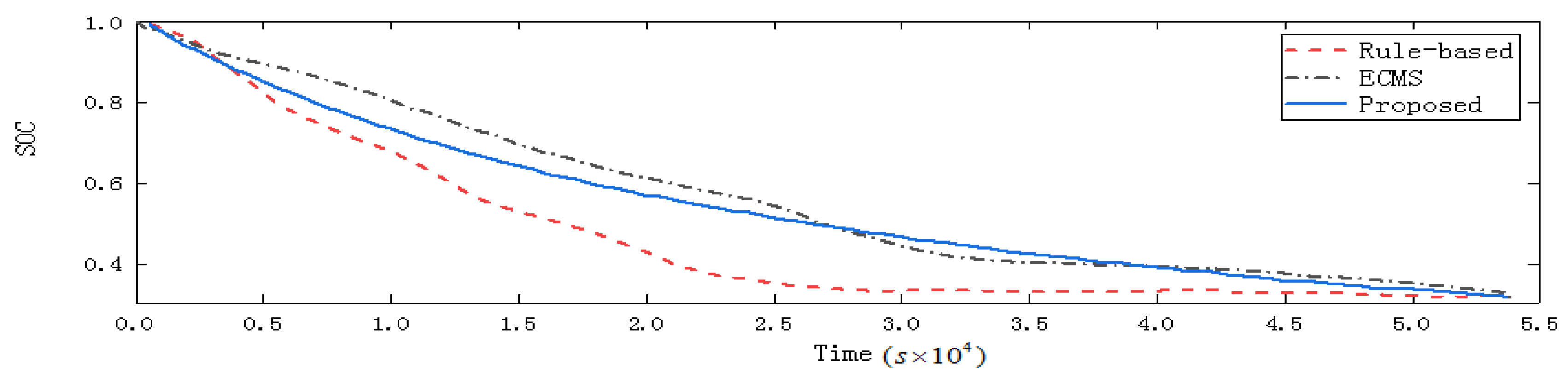
In this part, in order to evaluate the performance of the proposed real-time optimized control strategy, the rule-based control strategy and standard ECMS were taken as the benchmark. The simulation results are shown in Figure 16 and Table 3. As shown in Figure 16, for the three control strategies, the electricity energy stored in the battery is consumed to the expected lower limit in the end. Therefore, the electric consumption of the above strategies are similar with each other. However, the rule-based control strategy tends to deplete the battery energy in advance, the ECMS can consume the battery evenly throughout the routine, and the proposed methods have similar trends as the ECMS.
Furthermore, as shown in Table 3, under the similar electric consumption, the energy consumption produced by the proposed strategy is slightly higher than that produced by the standard ECMS but significantly lower than that of the rule-based control strategy. It is understandable from the results that the rule-based control strategy have the worst fuel economy by using experience to set rules, the ECMS takes advantage of local optimization about this driving cycle to achieve better fuel economy, whereas the adopted method considers the drivability of the vehicle to improve driving comfort at the expense of fuel consumption.
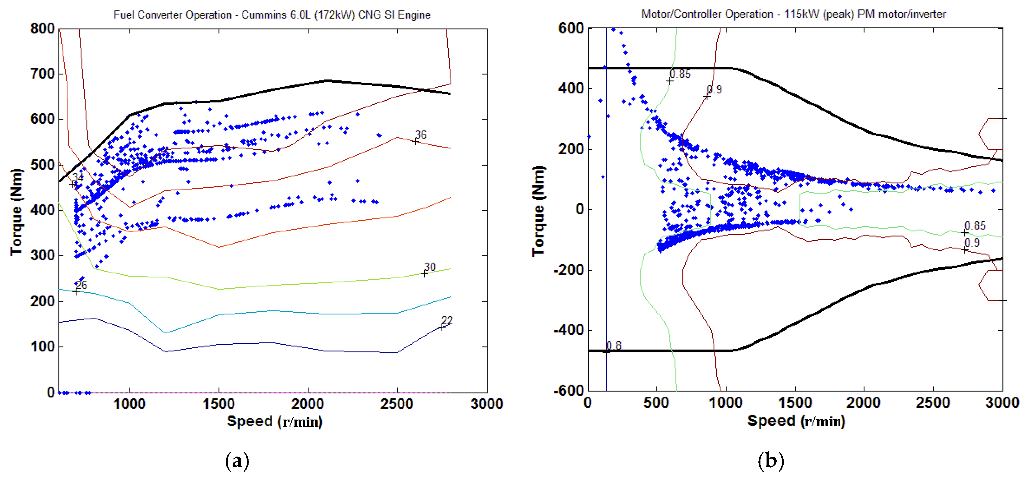
On the one hand, the optimization results of s(t) reflect the advantages of the proposed strategy, the vehicle controller would perform the more reasonable torque distribution combined with the optimized s(t), and then significantly reduce the fuel consumption. By the reasonable energy distribution of the proposed strategy, the working efficiency of the two power sources is high. As shown in Figure 17, most of the operating points of the engine are close to the engine optimal operating line, and the motor mainly runs in the high efficiency area. On the other hand the adopted method considers the drivability of the vehicle to improve driving comfort at the expense of fuel consumption.
5.3. Drivability
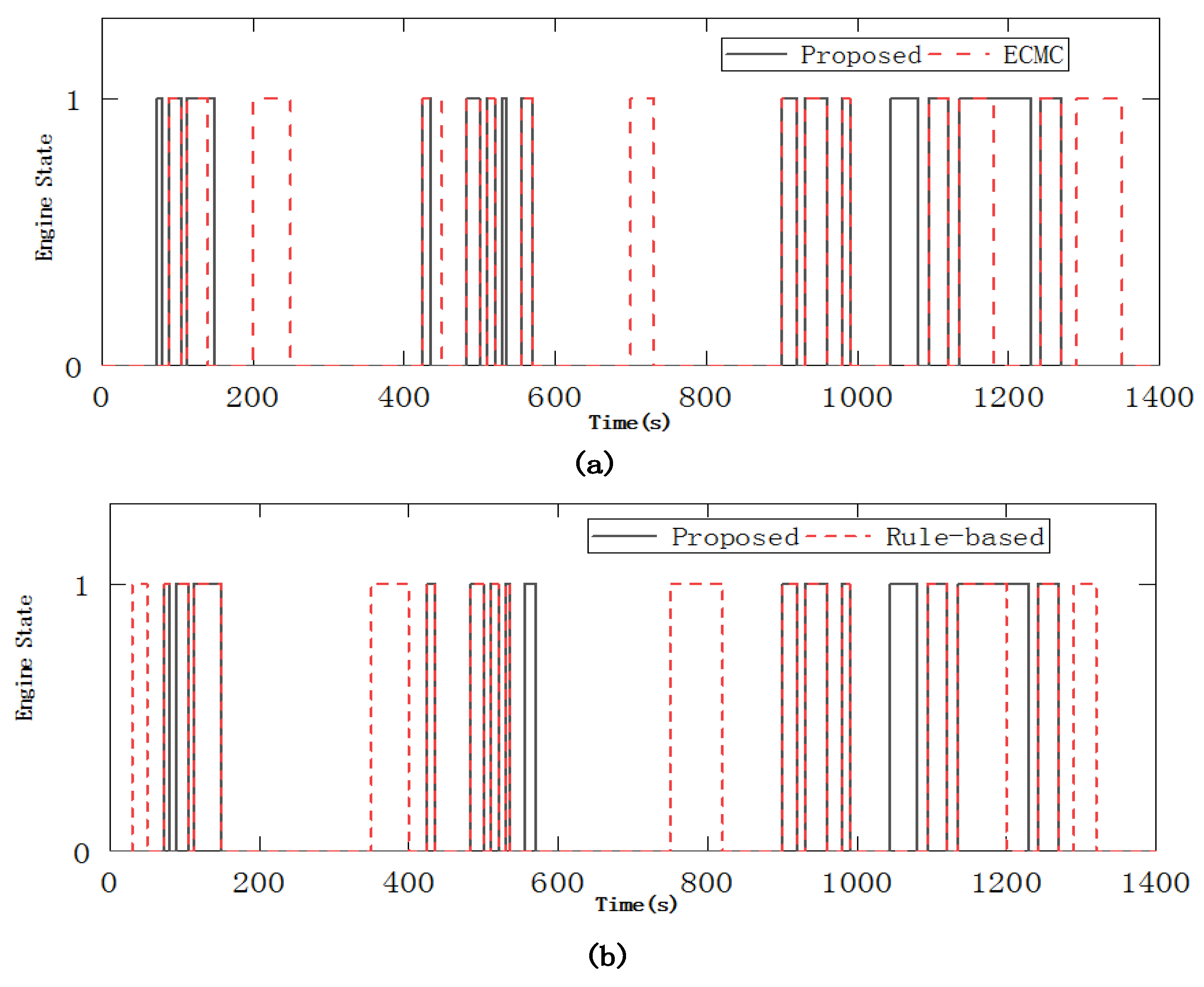
To highlight the advantages of the proposed strategy compared with the standard ECMS and the rule-based control strategy, some comparisons are carried out during the drivability of the PHEB in this part. According to the parameters extracted in Section 4.2 that affect the drivability of the vehicle, the comparison curve about shifting rules and engine start-stop status in the given driving cycle are shown in Figure 18 and Figure 19.
As shown in Figure 18, the proposed method has fewer gear-shifts than the other two strategies. At the same time, the number of engine starts-stops is less than with the other two strategies, as shown in Figure 19. Therefore, the energy management strategy proposed in this paper can improve the drivability of the vehicle and improve driving comfort.
Next, from the perspective of the overall performance, a quantitative comparative analysis of the three strategies is carried out. This paper introduces the overall performance index Jmulti to evaluate the control effect about fuel economy and the drivability in the form of weighted calculation of each indicator. The Jmulti can be written as:
where Mf is the fuel consumption per 100 km, the unit is m3/100 km, shift is the average number of shifts per kilometer, is the average number of start-stop per kilometer of engine.
Table 4 shows the simulation results of the three control methods under Beijing typical citybus driving cycle conditions. As shown in Table 4, compared with the rule-based control strategy, the ECMS has reduced fuel consumption, but since the ECMS does not consider the drivability, the gear-shifting frequency and engine start-stop times are as the same as the rule-based control strategy, the overall performance is only 6.61% improvement. However, though the EMS proposed in this paper has an increase in fuel consumption compared with ECMS, due to the influence of the drivability, the gear-shifting frequency and engine start-stop times are significantly reduced, so the overall performance is 18.54% improvement compared with the rule-based control strategy. Therefore, it can be concluded that the PHEB with the proposed strategy can reduce fuel consumption and improve the vehicle drivability simultaneously.
6. Conclusions
In this paper, a novel real-time optimal EMS based on parameter optimization for the single-shaft parallel PHEB with AMT is proposed. The work presented in this paper can be summarized as follows:
- (1)
- In response to the fuel economy problem, combined with the complex but regular characteristics of the bus routine, a linear weight particle swarm optimization algorithm was used to obtain the optimal array of s(t) by minimizing the fuel consumption. Considering the drivability of the PHEB, the DP algorithm was used to extract the parameters of the mode switching boundary and the AMT gear-shifting correction. Then, the novel algorithm is brought forward to improve the fuel economy and the drivability of the PHEB, combined with the s(t), gear-shifting correction and mode switching boundary parameters.
- (2)
- The proposed strategy was verified in a real-world driving cycle simulation. Results show that the proposed energy management strategy is effective in improving the fuel economy of the PHEB by moving the working points of the two power sources into the high-efficiency area. In addition, the results also verify that the proposed strategy ensures the drivability by their reduction of AMT gear-shifting frequency and the engine start-stop times. The overall performance is 18.54% improvement compared with the rule-based control strategy.
Author Contributions
This paper is the results of the hard work of all of the authors. Y.Y. and Y.Z. conceived and designed the proposed method. Y.Y. and J.T. conceived and analyzed the data; S.Z. contributed to the reviewing of the document, and Y.Y. wrote the paper. All authors gave advice for the manuscript.
Funding
This research received no external funding
Conflicts of Interest
The authors declare no conflict of interest.
References
- Martinez, C.M.; Hu, X.; Cao, D.; Velenis, E.; Gao, B.; Wellers, M. Energy Management in Plug-in Hybrid Electric Vehicles: Recent Progress and a Connected Vehicles Perspective. IEEE Trans. Veh. Technol. 2017, 66, 4534–4549. [Google Scholar] [CrossRef] [Green Version]
- Sun, F.; Xiong, R.; He, H. A systematic state-of-charge estimation framework for multi-cell battery pack in electric vehicles using bias correction technique. Appl. Energy 2016, 162, 1399–1409. [Google Scholar] [CrossRef]
- Amini, M.H.; Islam, A. Allocation of electric vehicle’s parking lots in distribution network. In Proceedings of the IEEE PES Innovative Smart Grid Technologies Conference (ISGT), Washington, DC, USA, 19–22 February 2014; pp. 1–5. [Google Scholar]
- Hu, X.; Moura, S.J.; Murgovski, N.; Egardt, B.; Cao, D. Integrated optimization of battery sizing, charging, and power management in plug-in hybrid electric vehicles. IEEE Trans. Control Syst. Technol. 2016, 24, 1036–1043. [Google Scholar] [CrossRef]
- Li, G.; Zhang, J.; He, H. Battery SOC constraint comparison for predictive energy management of plug-in hybrid electric bus. Appl. Energy 2017, 194, 578–587. [Google Scholar] [CrossRef]
- Wirasingha, S.G.; Emadi, A. Classification and Review of Control Strategies for Plug-In Hybrid Electric Vehicles. IEEE Trans. Veh. Technol. 2011, 60, 111–122. [Google Scholar] [CrossRef]
- Pisu, P.; Rizzoni, G. A comparative study of supervisory control strategies for hybrid electric vehicles. IEEE Trans. Control Syst. Technol. 2007, 15, 506–518. [Google Scholar] [CrossRef]
- Gao, Y.M.; Ehsani, M. Design and control methodology of plug-in hybrid electric vehicles. IEEE Trans. Ind. Electron. 2010, 57, 633–640. [Google Scholar]
- Banvait, H.; Anwar, S.; Chen, Y. A rule-based energy management strategy for plug-in hybrid electric vehicle (PHEV). In Proceedings of the 2009 American Control Conference, St. Louis, MO, USA, 10–12 June 2009; pp. 3938–3943. [Google Scholar]
- Peng, J.K.; Fan, H.; He, H.W.; Pan, D. A rule-based energy management strategy for a plug-in hybrid school bus based on a controller area network bus. Energies 2015, 8, 5122–5142. [Google Scholar] [CrossRef]
- Martínez, J.S.; John, R.I.; Hissel, D. A survey-based type-2 fuzzy logic system for energy management in hybrid electrical vehicles. Inf. Sci. 2012, 190, 192–207. [Google Scholar] [CrossRef]
- Li, S.G.; Sharkh, S.M.; Walsh, F.C.; Zhang, C.N. Energy and battery management of a plug-in series hybrid electric vehicle using fuzzy logic. IEEE Trans. Veh. Technol. 2011, 60, 3571–3585. [Google Scholar] [CrossRef]
- Denis, N.; Dubois, M.R.; Desrochers, A. Fuzzy-based blended control for the energy management of a parallel plug-in hybrid electric vehicle. Intell. Trans. Syst. IET 2015, 9, 30–37. [Google Scholar] [CrossRef]
- Chen, Z.; Mi, C.C.; Xiong, R.; Xu, J.; You, C. Energy management of a power-split plug-in hybrid electric vehicle based on genetic algorithm and quadratic programming. J. Power Sources 2014, 248, 416–426. [Google Scholar] [CrossRef] [Green Version]
- Arabali, A.; Ghofrani, M.; Etezadi-Amoli, M.; Fadali, M.S.; Baghzouz, Y. Genetic-algorithm-based optimization approach for energy management. IEEE Trans. Power Deliv. 2013, 28, 162–170. [Google Scholar] [CrossRef]
- Kum, D.; Peng, H.; Bucknor, N.K. Optimal energy and catalyst temperature management of plug-in hybrid electric vehicles for minimum fuel consumption and tail-pipe emissions. IEEE Trans. Control Syst. Technol. 2013, 21, 14–26. [Google Scholar] [CrossRef]
- Pu, J.; Yin, C. Optimal control of fuel economy in parallel hybrid electric vehicles. J. Autom. Eng. 2007, 221, 1097–1106. [Google Scholar] [CrossRef]
- Peng, J.; He, H.; Xiong, R. Rule based energy management strategy for a series–parallel plug-in hybrid electric bus optimized by dynamic programming. Appl. Energy 2017, 185, 1633–1643. [Google Scholar] [CrossRef]
- Chen, B.; Wu, Y.; Tsai, H. Design and analysis of power management strategy for range extended electric vehicle using dynamic programming. Appl. Energy 2014, 113, 1764–1774. [Google Scholar] [CrossRef]
- Zhang, S.; Xiong, R. Adaptive energy management of a plug-in hybrid electric vehicle based on driving pattern recognition and dynamic programming. Appl. Energy 2015, 155, 68–78. [Google Scholar] [CrossRef]
- Chen, Z.; Li, L.; Yan, B.; Yang, C.; Marina, M.C.; Cao, D. Multimode Energy Management for Plug-In Hybrid Electric Buses Based on Driving Cycles Prediction. IEEE Trans. Intell. Transp. Syst. 2016, 17, 2811–2821. [Google Scholar] [CrossRef]
- Chen, Z.; Xia, B.; You, C.; Mi, C.C. A novel energy management method for series plug-in hybrid electric vehicles. Appl. Energy 2015, 145, 172–179. [Google Scholar] [CrossRef]
- Li, J.; Wang, Y.; Chen, J.; Zhang, X. Study on energy management strategy and dynamic modeling for auxiliary power units in range-extended electric vehicles. Appl. Energy 2017, 194, 363–375. [Google Scholar] [CrossRef]
- Zhou, W.; Zhang, C.; Li, J.; Fathy, H.K. A Pseudospectral Strategy for Optimal Power Management in Series Hybrid Electric Powertrains. IEEE Trans. Veh. Technol. 2016, 65, 4813–4825. [Google Scholar] [CrossRef]
- Zou, C.F.; Manzie, C.; Nesic, D. Model Predictive Control for Lithium-Ion Battery Optimal Charging. IEEE-ASME Trans. Mechatron. 2018, 23, 947–957. [Google Scholar] [CrossRef]
- Zou, C.; Hu, X.; Wei, Z.; Tang, X. Electrothermal dynamics-conscious lithium-ion battery cell-level charging management via state-monitored predictive control. Energy 2017, 141, 250–259. [Google Scholar] [CrossRef]
- Kermani, S.; Delprat, S.; Guerra, T.M.; Trigui, R.; Jeanneret, B. Predictive energy management for hybrid vehicle. In Proceedings of the 2008 IEEE Vehicle Power and Propulsion Conference, Harbin, China, 3–9 September 2012; pp. 408–420. [Google Scholar]
- Sun, C.; Hu, X.S.; Moura, S.J.; Sun, F.C. Velocity predictors for predictive energy management in hybrid electric vehicles. IEEE Trans. Veh. Technol. 2015, 23, 1197–1204. [Google Scholar]
- Cairano, S.D.; Bernardini, D.; Bemporad, A.; Kolmanovsky, I.V. Stochastic MPC with learning for driver-predictive vehicle control and its application to HEV energy management. IEEE Trans. Veh. Technol. 2014, 22, 1018–1031. [Google Scholar] [CrossRef]
- Musardo, C.; Rizzoni, G.; Staccia, B. A-ECMS: An adaptive algorithm for hybrid electric vehicle energy management. Eur. J. Control 2005, 11, 1816–1823. [Google Scholar] [CrossRef]
- Feng, T.; Lin, Y.; Gu, Q.; Hu, Y. A supervisory control strategy for plug-in hybrid electric vehicles based on energy demand prediction and route preview. IEEE Trans. Veh. Technol. 2015, 64, 1691–1700. [Google Scholar]
- Kessels, J.T.B.A.; Koot, M.W.T.; Bosch, P.P.J.; Kok, D.B. Online energy management for hybrid electric vehicles. IEEE Trans. Veh. Technol. 2008, 57, 3428–3440. [Google Scholar] [CrossRef]
- Zhao, D.; Stobart, R.; Dong, G.; Winward, E. Real-time energy management for diesel heavy duty hybrid electric vehicles. IEEE Trans. Veh. Technol. 2015, 23, 829–841. [Google Scholar]
- Du, Y.; Zhao, Y.; Wang, Q.; Zhang, Y.; Xia, H. Trip-oriented stochastic optimal energy management strategy for Plug-in Hybrid Electric Bus. Energy 2016, 115, 1259–1271. [Google Scholar] [CrossRef]
- Johri, R.; Baseley, S.; Filipill, Z. Simultaneous optimization of supervisory control and gear shift logic for a parallel hydraulic hybrid refuse truck using stochastic dynamic programming. In Proceedings of the ASME Dynamic Systemsand Control Conference, Arlington, TX, USA, 31 October–2 November 2011; pp. 99–106. [Google Scholar]
- Li, L.; Yang, C.; Zhang, Y.; Zhang, L.; Song, J. Correctional DP-Based Energy Management Strategy of Plug-In Hybrid Electric Bus for City-Bus Route. IEEE Trans. Veh. Technol. 2015, 64, 2792–2803. [Google Scholar] [CrossRef]
- Li, L.; Yan, B.; Yang, C.; Zhang, Y.; Chen, Z.; Jiang, G. Application-Oriented Stochastic Energy Management for Plug-in Hybrid Electric Bus with AMT. IEEE Trans. Veh. Technol. 2016, 65, 4459–4470. [Google Scholar] [CrossRef]
- Yang, C.; Du, S.; Li, L.; You, S.; Yang, Y.; Zhao, Y. Adaptive real-time optimal energy management strategy based on equivalent factors optimization for plug-in hybrid electric vehicle. Appl. Energy 2017, 203, 883–896. [Google Scholar] [CrossRef]
Figure 1.
Configuration of the PHEV powertrain.

Figure 2.
Fuel consumption contour map of engine.

Figure 3.
Efficiency diagram of the motor/generator.

Figure 4.
Rint model of the battery.

Figure 5.
Fitting results of the open circuit voltage and soc.

Figure 6.
Control scheme of the proposed strategy.

Figure 7.
Flowchart of solution process of s(t).

Figure 8.
The distribution of AMT gear-shifting loci in three driving cycle conditions. (a) Manhattan; (b) China typical; (c) WVUSUB.
Figure 8.
The distribution of AMT gear-shifting loci in three driving cycle conditions. (a) Manhattan; (b) China typical; (c) WVUSUB.

Figure 9.
The distribution of operating points of engine and motor in three driving cycle conditions. (a) Manhattan; (b)China typical; (c) WVUSUB.
Figure 9.
The distribution of operating points of engine and motor in three driving cycle conditions. (a) Manhattan; (b)China typical; (c) WVUSUB.

Figure 10.
AMT gear-shifting correction.

Figure 11.
Mode switching boundary parameters.

Figure 12.
Beijing typical citybus driving cycle.

Figure 13.
Overall simulation results of PHEB in real-time control strategy. (a) vehicle speed; (b) the battery SOC; (c) engine power; (d) motor power.
Figure 13.
Overall simulation results of PHEB in real-time control strategy. (a) vehicle speed; (b) the battery SOC; (c) engine power; (d) motor power.

Figure 14.
Simulation results for a single driving cycle 1 (1). (a) the simulated vehicle speed and the actual vehicle speed; (b) the battery SOC.
Figure 14.
Simulation results for a single driving cycle 1 (1). (a) the simulated vehicle speed and the actual vehicle speed; (b) the battery SOC.


Figure 15.
Simulation results for a single driving cycle (2). (a) the value of the s(t); (b) engine torque and motor torque; (c) engine state; (d) AMT gear position.
Figure 15.
Simulation results for a single driving cycle (2). (a) the value of the s(t); (b) engine torque and motor torque; (c) engine state; (d) AMT gear position.


Figure 16.
SOC comparison between three strategies.

Figure 17.
(a) Operating points of the engine; (b) Operating points of the EM.

Figure 18.
Comparison of engine start-stop times between three strategies. (a) the proposed strategy and the ECMC; (b) the proposed strategy and the rule-based strategy.
Figure 18.
Comparison of engine start-stop times between three strategies. (a) the proposed strategy and the ECMC; (b) the proposed strategy and the rule-based strategy.

Figure 19.
ATM gear-shifting frequency comparison between three strategies.


Table 1.
Main parameters of the PHEB.
| Items | Detailed Information |
|---|---|
| Total vehicle mass | 18,000 kg |
| Engine | CNG, 5.9 L, nominal power: 172 kw, Max torque: 678 Nm |
| EM | Permanent magnet, max torque: 750 Nm, Nominal/peak power: 70 kw/115 kw |
| Battery | Capacity: 120 Ah, voltage: 336 V |
| AMT | 5-speed, gear ratio: (6.11, 3.66, 2.17, 1.42, 1) |
| Final drive | 6.14 |
Table 2.
The statistics of the Beijing typical citybus driving cycle.
| Cycles | Driving Time | Travel Distance | Average Speed | Maximum Speed | Maximum Acceleration | Maximum Deceleration |
|---|---|---|---|---|---|---|
| 1 | 1804 s | 6.81 km | 13.6 km/h | 63.8 km/h | 2.33 m/s2 | −3.44 m/s2 |
Table 3.
Energy consumption comparison.
| Strategy | CNG Consumption (m3/100 km) | Final SOC (%) | Improvement (%) |
|---|---|---|---|
| Rule-based | 36.45 | 30.25 | — |
| ECMS | 31.67 | 30.12 | 13.11 |
| Proposed | 32.24 | 30.15 | 11.55 |
Table 4.
Comprehensive performance comparison.
| EMC | Mf (m3/100 km) | Shift | State | Comprehensive Evaluation | |
|---|---|---|---|---|---|
| Jmulti | Improvement | ||||
| Rule-based | 36.45 | 7.58 | 7.46 | 62.86 | — |
| ECMS | 31.67 | 7.65 | 7.90 | 58.70 | 6.61% |
| Proposed | 32.24 | 5.29 | 5.73 | 51.20 | 18.54% |
© 2018 by the authors. Licensee MDPI, Basel, Switzerland. This article is an open access article distributed under the terms and conditions of the Creative Commons Attribution (CC BY) license (http://creativecommons.org/licenses/by/4.0/).
Share and Cite
MDPI and ACS Style
Yang, Y.; Zhang, Y.; Tian, J.; Zhang, S. Research on a Plug-In Hybrid Electric Bus Energy Management Strategy Considering Drivability. Energies 2018, 11, 2177. https://doi.org/10.3390/en11082177
AMA Style
Yang Y, Zhang Y, Tian J, Zhang S. Research on a Plug-In Hybrid Electric Bus Energy Management Strategy Considering Drivability. Energies. 2018; 11(8):2177. https://doi.org/10.3390/en11082177
Chicago/Turabian StyleYang, Ye, Youtong Zhang, Jingyi Tian, and Si Zhang. 2018. "Research on a Plug-In Hybrid Electric Bus Energy Management Strategy Considering Drivability" Energies 11, no. 8: 2177. https://doi.org/10.3390/en11082177
Note that from the first issue of 2016, this journal uses article numbers instead of page numbers. See further details here.