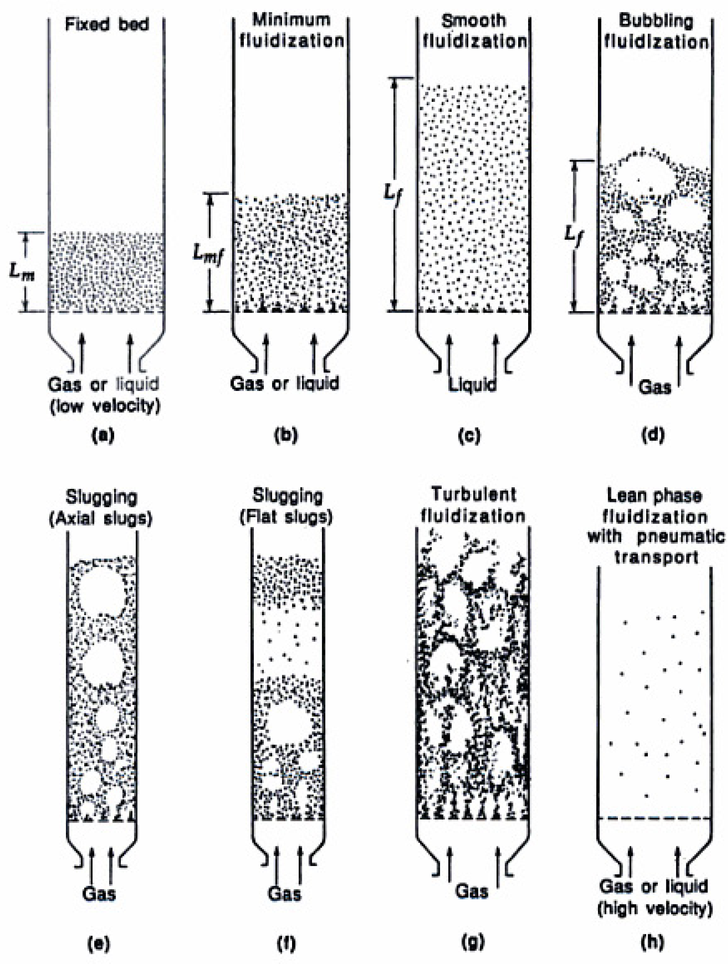
Figure 9.
Visualization of different vertical gas-solid flow regimes [
46].
3.2.1. Fluidization Media
The stoichiometric oxygen ratio is commonly used for the identification of different “oxidation regimes” during a thermochemical fuel conversion process. This parameter, also called “equivalence ratio”, “air factor” or “air ratio”, is represented by the symbol
λ (lambda). From the formula given in the previous paragraph it is clear that
1 refers to combustion processes,
λ = 0 to pyrolysis, and 0
1 to gasification, see also
Table 4. With the aim to produce a gas suitable for transportation fuels synthesis application, high yields of H
2 and CO are required; this can be achieved in low lambda value regions. On the other hand, partial oxidation of the fuel is necessary to generate heat to drive the mostly endothermic gasification reactions and allow the reactor to work in the autothermal mode.
Table 9.
Main process variables and parameters, and their interactions assuming only one variable changing (increasing) at a time. Variables in bold face are discussed in more detail in the text. Symbols used: + (increase), – (decrease), OPT (optimal range exists to maximize or minimize the desired effect), x (other effect, see footnote).
| | Input | | Output |
|---|
| Variable | λ | SB | , | T | | CC | CGE | tar yield |
| biomass feed rate | – | – | | – | | – | + | + |
| oxygen feed rate | + | | + | + | | + | – | + |
| steam feed rate | | + | + | – | | OPT | OPT | OPT |
| process pressure | | | – | | | – | + | – |
| kind of bed material | | | x | | | xe | xe | – |
| used additive | | | | | | xe | xe | x |
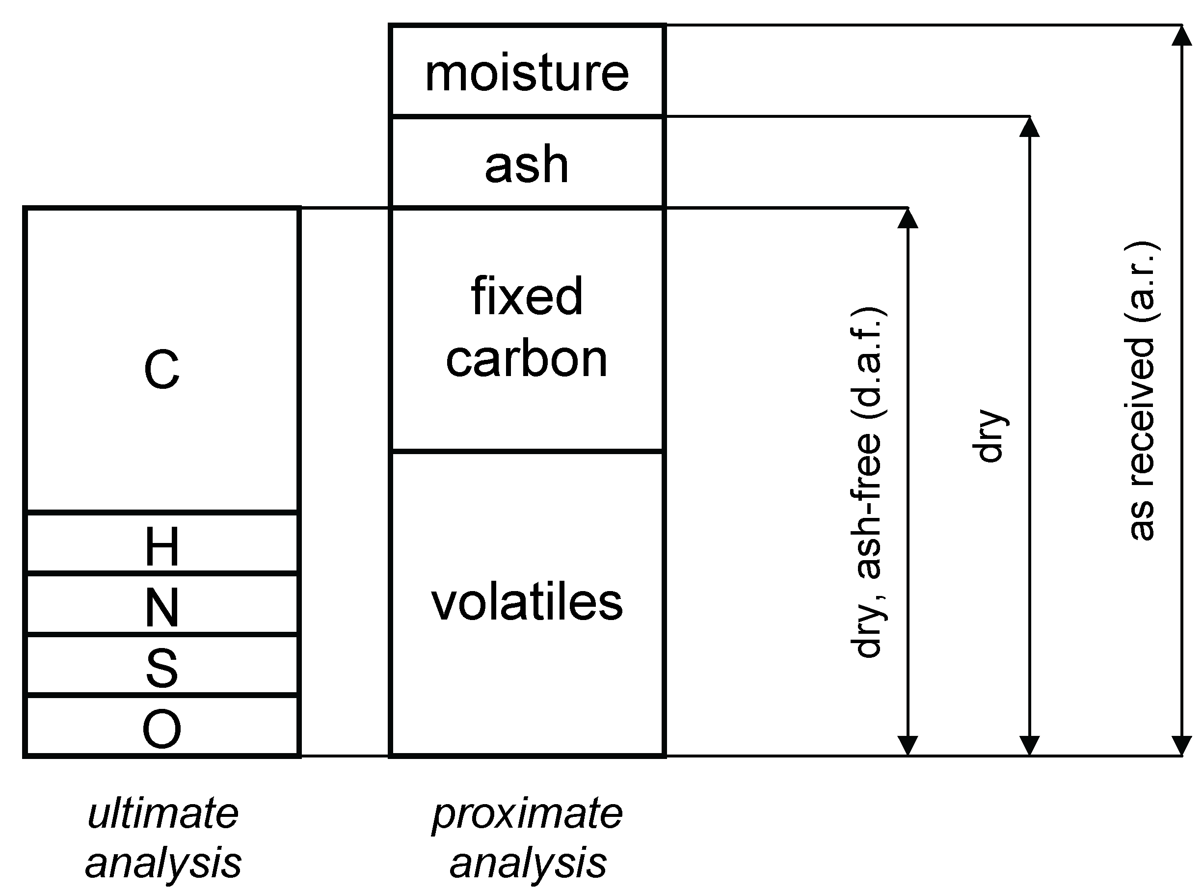
The most common fluidization and oxidation medium used in gasification processes is air. Although air is cheap and abundant, the fact that the nitrogen present in air cannot be easily separated from the product gas is a significant drawback of that gasification medium. Air gasification produces gas of low calorific value, and approximately 50% of the volume of the product is the inert nitrogen. Therefore it would be better to use a combination of gases that will either react to form useful products or will be easily separated from the final product stream. The gasification agent will typically consist of a gas that provides the necessary oxygen for partial oxidation of the fuel and a gas that will act as a moderator/fluidization medium, unless the heat to drive the strongly endothermal reactions is supplied externally, e.g., from the combustion of char, as in a dual (or: indirect) gasifier—then gasification with pure steam is possible. For a direct gasifier a mixture of pure oxygen and steam fulfils the criteria mentioned above and both gases are very common in process industry. Besides acting as a fluidization medium steam is also a reactant in many gasification reactions, therefore its presence and amount have an influence on the product gas composition. The amount of steam supplied to the process is often related to the amount of biomass feed in a so-called steam-to-biomass ratio (SB). In the literature it is not often mentioned whether the fuel feed is given on an “as received” or “dry (and ash-free)” basis. However, in case of fuels with higher moisture and/or ash content, the difference in the calculated SB will be significant, depending on the choice of the denominator. Additionally, the moisture present in the fuel should not be neglected in the calculation of the SB, as the resulting steam will be the first to interact with the organic part of the fuel upon devolatilization in the reactor. Also in case of fuels with higher moisture content the amount of steam that originates from the fuel will not be negligible compared to the overall steam input. Considering the above, a modified steam-to-biomass ratio (SB
) is proposed. Regarding the effect of the fuel moisture van der Drift concluded that the water content of raw biomass will be one of the most dominant fuel characteristics influencing carbon conversion, cold gas efficiency and the heating value of the gas [
48].
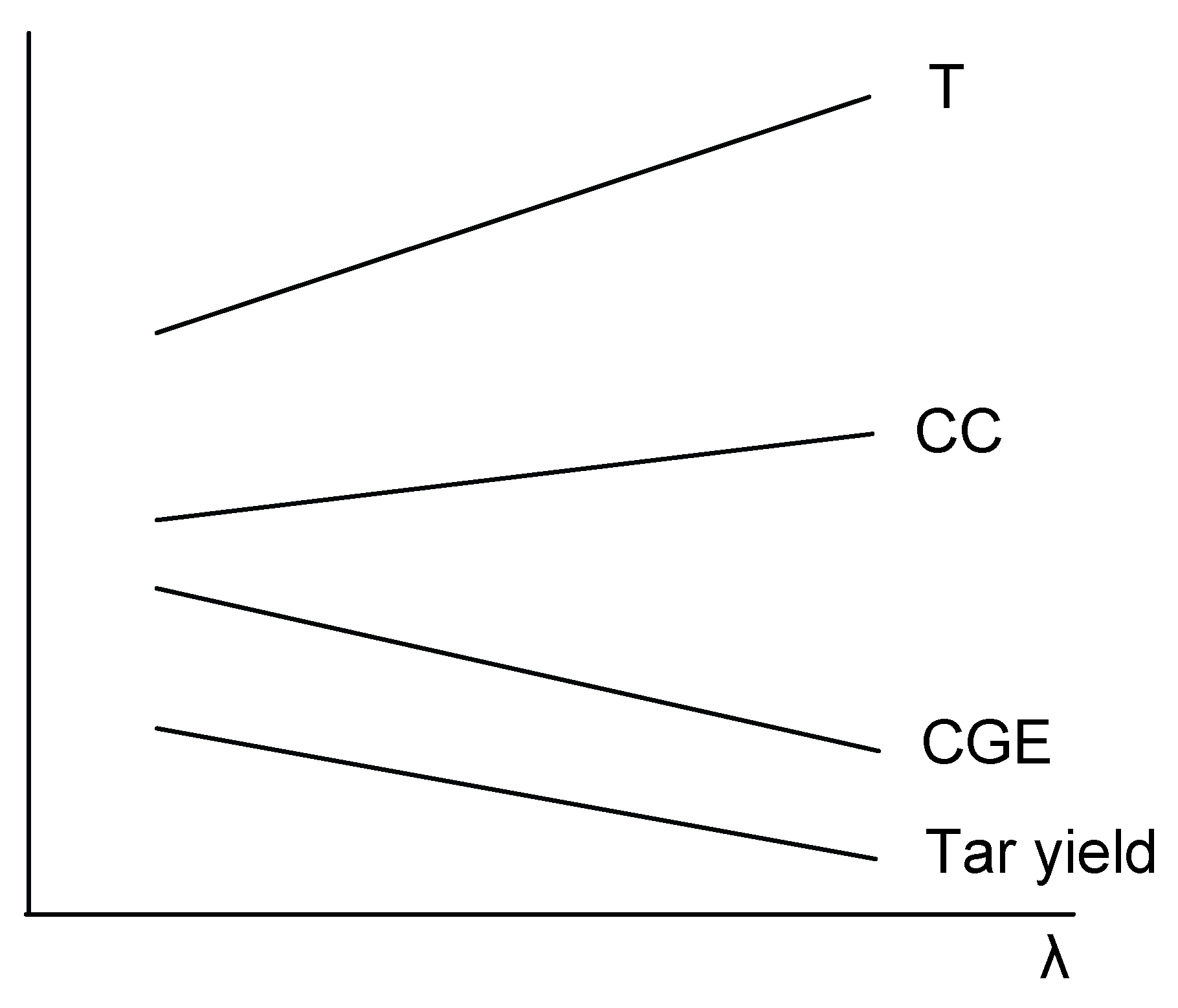
The effect of
λ on the main output parameters is depicted in
Figure 10. Higher availability of oxygen will lead to increased combustion of the product gas and char, and therefore to an increase of the reactor temperature and the carbon conversion. However, the yield of the combustible products and thus also the cold gas efficiency will decrease. Tar yield will decrease with increasing
λ, partially due to oxidation reactions and partially due to enhanced tar cracking caused by the increased process temperature. Considering the above, the choice of
λ will be a compromise; the typical values used in fluidized bed gasification processes vary between 0.2 and 0.4.
Figure 10.
Effect of the variation of λ on the main process parameters.
Figure 10.
Effect of the variation of λ on the main process parameters.
A similar consideration applies to the SB value. Here, however, a larger variation in the suggested optimal values has been found in the literature.
Table 10 shows the results of the investigations on the effect of SB on the gasification process. Most researchers concluded that choosing the SB value between 0.3 and 1.0 will have a positive effect on carbon conversion, cold gas efficiency, hydrogen yield and tar reduction. However it has to be stated that all the investigations reported in
Table 10 have been carried out using BFBs. CFBs operate at a higher fluidization velocity, and therefore a higher steam input may be needed to achieve this. Nonetheless, the higher the SB ratio the more energy is required to heat up the steam to process temperature, which at some point will cancel the positive effect on the CGE. In addition, higher values (SB >1) lead to a high amount (>60%
) of unreacted H
2O in the product gas, which, even when the recycling via condensation/vaporization/reheat is applied, will cause a significant drop in the thermal efficiency of the whole process [
73]. Also, the conversion of H
2O decreases with increasing SB ratio, and is typically limited to approximately 10% [
73,
74].
Table 10.
The results of several investigations related to SB.
Table 10.
The results of several investigations related to SB.
| Literature | Test | Investigated | Investigated | Reported | Remarks |
|---|
| Reference | Equipment | Variable | Range | Optimal Range | |
|---|
| Corella [73] | BFB | SB | 0.2–2.0 | 0.40–1.0 | values higher than 1.2–1.5 not recommended |
| Campoy [75] | BFB | SB | 0–0.63 | 0.3–0.4 | slight positive effect on CC and CGE |
| | | | | | increased H2 yield from 8.7 to 13.3% and |
| | | | | | 17.8 to 27.7 g kg |
| | | | | | decrease of the total yield of main combustibles |
| | | | | | from 555 to 507 g kg |
| Franco [76] | BFB | SB | 0.4–0.85 | 0.6–0.7 | maximum for CC, gas yield and H2 |
| | | | | | concentration in the gas |
| Gil [77] | BFB | SB | 0.3–1.3 | 0.50–0.75 | max. H2 concentration of 29% |
| | | | | | very difficult to obtain tar concentration |
| | | | | | below 5–10 g m |
The increase in the hydrogen yield due to steam addition cannot be explained solely by the water-gas shift reaction, as the changes in H
2 and CO concentrations do not match. It is highly probable that the added steam acts as an oxygen donor for the oxidation of CO, char and perhaps also tar. This could be confirmed by the results presented in [
75], which show a slightly increased carbon conversion and a slightly decreased cold gas efficiency when comparing the extreme SB ratios investigated there.
Kinoshita
et al. [
40] performed some tests in an air-blown bench-scale FB gasifier to test the influence of process temperature, equivalence ratio and residence time on the formation of tar species. Tar yield, expressed in g kg
showed a maximum at the temperature of
ca. and decreases with increasing temperature (
λ = 0.22,
τ = 3.75 s). Tar yield also decreased with increasing equivalence ratio (range: 0.22–0.32) at
constant temperature, while the influence of the residence time in the studied interval (3.0–5.0 s) was negligible. Next to the total (measurable) tar, the yields of different tar classes were studied. The increase in temperature caused a large increase of the benzene fraction, while other monoaromatics decreased. At the same time naphthalene fraction increased, just as the fractions of 3 and 4-ring compounds, but the fraction of 2-ring compounds other than naphthalene decreased in the studied temperature range (700–900
). The oxygenated compounds (e.g., phenol) were absent in the temperatures above 800
. A very similar trend is observed for an increasing equivalence ratio at
constant temperature, except the fact that here also the 2-ring compounds other than naphthalene showed an increasing trend. The effect of the residence time on the tar composition is much less pronounced than that of the temperature or the equivalence ratio; mainly a linear decrease of monoaromatic compounds other than benzene, and an increase of 3- and 4-ring compounds at higher residence times (>4.5 s) were observed. It is very likely that the influence of the residence time would be much more pronounced at lower values (
1 s).
3.2.3. Pressure
Although pressurized operation puts significant additional requirements on the design and operation of a gasifier, it is often desirable. Firstly, higher pressures result in lower volumetric gas flow rates, which means smaller size of the reactor and downstream gas cleaning and upgrading equipment. Secondly, many downstream processes using the produced syngas require pressurized conditions (e.g., Fischer-Tropsch process, gas turbines), and the fact is that it is easier to pressurize the reactants separately (lock-hopper system for the solids, compressors for the gases) than to compress hot, combustible, hydrogen-rich product gas compensates the technical and operational complications [
44]. Compressing the product gas will require removal of tar and moisture below their dew points to avoid condensation during compression. Also the cooling of the gas to approximately 90
is required [
22]. However, process improvements are still needed, for instance in the high-pressure feeding systems, although commercially available units exist [
78].
Pressurized conditions will also influence the process of gasification. The equilibrium reactions that are not equimolar (reactions 6, 7, 9, 10, 11) will be driven towards the condition with the lowest volume (Le Chatelier’s principle). In the list of the main gasification reactions, three out of five non-equimolar reactions involve methane, therefore the methane yield from the pressurized gasification process will be higher than from an atmospheric process performed at otherwise similar conditions. The tar yield will, however, go down with increasing pressure; this is due to the fact that during the pyrolysis phase the recarbonisation of the tar precursors will be more pronounced as the pressure increases. Some of the carbon formed will subsequently react to methane, but generally the carbon conversion will also decrease with increasing pressure [
79].
Additional benefits from the pressurized conditions could be achieved by operating the gasifier under pressure conditions that favor the recarbonization of CO
2 on earth-alkaline species, typically calcium. Under atmospheric gasification conditions the typical partial pressures of CO
2 would require a temperature well below 800
to enter the thermodynamic region where CaCO
3 is formed. However, such a low gasification temperature will result in lower carbon conversion and an increased tar yield. By increasing the operational pressure of the gasifier and thus also the partial pressure of CO
2 the typical fluidized bed gasification temperatures can be maintained while benefiting from the CO
2 capture by recarbonization. The enhanced hydrogen production by the adsorption of CO
2 was studied by several authors: enhanced high-temperature WGS [
80], adsorption enhanced reforming [
64,
65], HyPr-RING (Hydrogen Production by reaction-integrated novel gasification) [
81], and also its application for post-combustion CO
2 removal has been investigated [
82].
3.2.4. Bed Materials & Additives—Catalytic Activity on Gasification Reactions
The main purpose of the presence of the bed material in the fluidized bed is the heat storage and heat transfer between the particles undergoing exothermic processes (chemical reactions like oxidation and water-gas shift) and endothermic processes (drying, pyrolysis, and most gasification reactions). The heat produced during exothermic processes is “stored” (accumulated) in the bed material and due to intense mixing of the bed inventory (fluidization) it is transferred to the processes that require heat input. In this way large temperature peaks in the oxidation zone are avoided and a nearly uniform temperature distribution can be observed in the bubbling zone (BFB) or even throughout the reactor (CFB).
In principle the bed material is assumed to remain inert during the gasification process. To a large extent this is true for the bed material used most often—quartz sand. However, the choice of the bed material can have an important influence on the process if that bed material shows catalytic activity on some of the reactions involved, or its interaction with the fuel constituents results in a considerable change of its physical properties. The former effect is mostly desirable, as in the case of gasification it often leads to the increased conversion rate of tar, leading to an improved gas quality. In the latter case the most often observed effect is called bed agglomeration, which is highly undesirable—this will be discussed in the next section.
Using catalytically active bed materials can significantly influence the gas composition in terms of increased hydrogen yield, and reduced amounts of methane and tar, bringing the gas closer to syngas composition. These materials can also be applied as in-bed additives—an important feature of a fluidized bed. Regarding the tar decomposition, the ability to use metal oxides derived from natural rock minerals in the fluidized bed (as primary tar measures) appears to be more advantageous than the use of (commercial) Ni-based catalyst. This is due to the fact that the loss of solids, and of the fine fraction in particular, is often not negligible in these kind of reactors [
39,
83,
84]. Dolomites (CaMg(CO
3)
2), calcites (CaCO
3), magnesites (MgCO
3) and olivines ((Mg,Fe)
SiO
4) are potentially attractive in-bed additives or even bed materials because they are non-toxic and can be significantly active at high temperatures. The main problem of the minerals mentioned above, with the exception of olivine, is their low attrition resistance and the continuous deterioration of their mechanical strength over the reaction time. In addition, the costs of catalysts are usually high; this is especially true for metal-based catalysts, while the prices of natural rock minerals are often higher than quartz sand, but acceptable. Furthermore, most of the additives have been tested only on (laboratory-)pilot scale, although olivine [
16] and magnesite [
85] have also been tested in larger plants.
Delgado
et al. [
86] reported that of the three natural rock minerals applied in the downstream fixed bed reactor for the upgrading of the product gas, calcined dolomite (CaO–MgO) showed the highest catalytic activity on tar cracking, followed by pure calcined magnesite (MgO) and calcined calcite (CaO). Also relatively low deactivation was observed for tar concentrations below 48 g m
(which is even higher than the typical tar concentrations measured in reasonably operating (C)FB gasifiers), at temperatures above 800
, when small particles are applied (d < 1.9 mm) [
87]. An additional advantage was the simultaneous coke formation and its elimination by steam gasification, leading to the prolonged lifetime of the catalyst. The integration of the heats of CO
2 adsorption reaction and water-gas shift reaction into the complex network of (endothermal) gasification reactions will lead to the improvement of the product gas in terms of higher hydrogen yield and reduced amount of tar [
64,
83,
86,
87,
88,
89]. Hanping
et al. [
90] performed air-blown biomass gasification tests in a small-scale (
ca. 12 kW
) CFB gasifer with the addition of dolomite, magnesite and olivine, and although they reported a significant reduction (>50%) of tar content in the gas, they did not report any values showing the change in the concentration of the permanent gases, except in the dolomite case where only the concentration of H
2 increased significantly. For magnesite, used both as an additive and as the bed material in a steam/oxygen blown CFB gasifier (100 kW
), the positive effect on the conversion of tar and methane, and an increase of H
2:CO ratio was presented in detail by Siedlecki
et al. [
89].
Devi
et al. [
91] compared the effect of dolomite and fresh olivine on the conversion of tar, by using these minerals as additives to a sand bed in an air-blown BFB gasifier. Both additives showed a reduced tar concentration in the product gas, as compared to pure sand bed, but the highest tar conversion was achieved with dolomite. The effect of the pre-treatment (calcination at 900
) of olivine was also investigated, using steam- and dry reforming of naphthalene as the model tar conversion component and reaction [
92]. Pre-treated olivine proved to be a significantly more active catalyst under the mentioned conditions than the untreated one. Also the calcination time was observed to play a role with a 30% and 80% increase in naphthalene conversion for 1 hour and 10 hours treatment, respectively. However, under model syngas atmosphere the conversion was lower than only in the presence of steam and CO
2. This can be attributed to the presence of H
2 and CO in the gas, as these species are known inhibitors of tar reforming reactions (see also e.g., [
93]). Also the origin of olivine, and more precisely its mineral composition, will influence its activity related to the conversion of tar. Rauch
et al. [
94] compared the influence of two different kinds of olivine on the tar yield and the gas composition during the operation of the Güssing 8 MW
CHP demo-plant supported by detailed characterization of the bed material. The researchers came to the conclusion that the presence of free iron oxide outside the olivine structure is very likely a possible requirement for the desired catalytic activity. Siedlecki and de Jong [
95] observed the lack of the activity of a certain kind of olivine on tar yield, even despite the calcination pre-treatment at two different temperatures (900
and 1200
, 10 hours). On the other hand Corella [
73] compared the use of different catalytically active bed materials, using the H
2 and tar concentration (both on dry gas basis) as a benchmark for gas composition and gas quality respectively. Based on those experiments it was concluded that olivine is a promising catalytic bed material resulting in a hydrogen concentration varying between 34–52%
, while the reported tar content varied between 0.25–1.5 g m
[
73,
94].
Char, although it is hard to call it an “additive”, as it is always present in the bed except during startup, has also been recognized as an important catalyst for the conversion of hydrocarbons—both tar [
96] and methane [
97]. Detailed comparison of various catalysts for tar conversion showed that the activity of char for naphthalene conversion is even higher than dolomite at 900
[
98]. The high activity of char is partially attributed to the fact that it is continuously activated by steam and CO
2, and above that, there is a continuous supply of fresh char from biomass pyrolysis. However, in order to use char efficiently as an in-situ catalyst the fluidized bed should be designed in a way to allow long char-tar interaction times. In a standard (C)FB this is limited only to the devolatilization phase and the stochastic interaction between upflowing gas and fluidized char particles. Also Brage [
99] claims that the holdup of char in the reactor results in the decreased amount of tar in the gas, being a proof of the catalytic activity of char on tar conversion mechanisms. In addition, he states that coal char is more active than biomass char, as higher coal char holdups can be achieved, due to lower reactivity of coal char.
3.2.5. Bed materials & Additives—Agglomeration Resistance and Counteractions
As already explained in the previous section, in principle the bed material is assumed to remain inert during the gasification process, but its interaction with the fuel constituents may result in a considerable change of its physical properties. This highly undesirable effect is called bed agglomeration. The research performed in this area indicates that bed agglomeration will occur upon the interaction between the silica-containing bed material and the inorganic part of the fuel (
i.e., ash), especially if the latter contains high amounts of alkali metals and/or chlorine. During biomass conversion when alkali compounds are released, and also when silica is present either from the bed material or biomass ash itself, then the formation of alkali-silicates (K
2O-SiO
2) can be expected. Those compounds have an eutectic point of about 770
, while the eutectic point of K
2O-CaO-SiO
2 structures is even lower [
100]. Ergudenler [
101] found that quartz sand will agglomerate in the presence of straw ash (with 1.2%
of K
2O in the dry fuel) at around 800
, causing defluidization. This has also been observed and investigated by other researchers [
36,
101,
102,
103,
104]. From the above it can be concluded that silica-containing bed materials should be avoided when operation with “difficult” biomass fuels is intended. Natural rock minerals, already introduced in the previous section as catalytically active bed materials or additives could be an option here, but their mechanical strength is often much lower than that of silica-based materials and therefore they are very prone to attrition. As an alternative synthetic bed materials (e.g., alumina) could be employed, but their high price—especially important when applied on a larger scale—will be an obstacle here. Therefore the choice of the bed material will be a compromise between mechanical stability, agglomeration resistance, catalytic activity and price.
In case a silica-rich bed material is to be used with alkali-rich fuels the agglomeration problem can be counteracted using in-bed additives. Known additives that are supposed to reduce the agglomeration phenomena are kaolin (Al
2Si
2O
5(OH)
4), calcium oxide, calcium carbonate and bauxite [
105]. Introduction of alumina-rich compounds, such as kaolin, may result in the formation of alkalialuminum silicates (K
2O-Al
2O
3-SiO
2), which have a much higher melting temperature than the alkali silicates (K
2O-SiO
2) formed otherwise [
100]. Siedlecki and de Jong [
95] reported successful application of kaolin during the gasification of miscanthus and Dutch straw, both containing a high amount of alkaline elements in the ash, when silica-rich bed materials (sand and olivine) were used—no agglomeration occurred during the operation with the additive, while agglomeration was reported during the test when no additive was used. Also the gasification tests with demolition wood (“B-quality” wood), a fuel that judging from its ash amount and composition should not cause any agglomeration-related problems, ended up with defluidization. There too the addition of kaolin proved to be a sufficient remedy.


