Preliminary Design of a Multi-Column TLP Foundation for a 5-MW Offshore Wind Turbine

Abstract
:1. Introduction
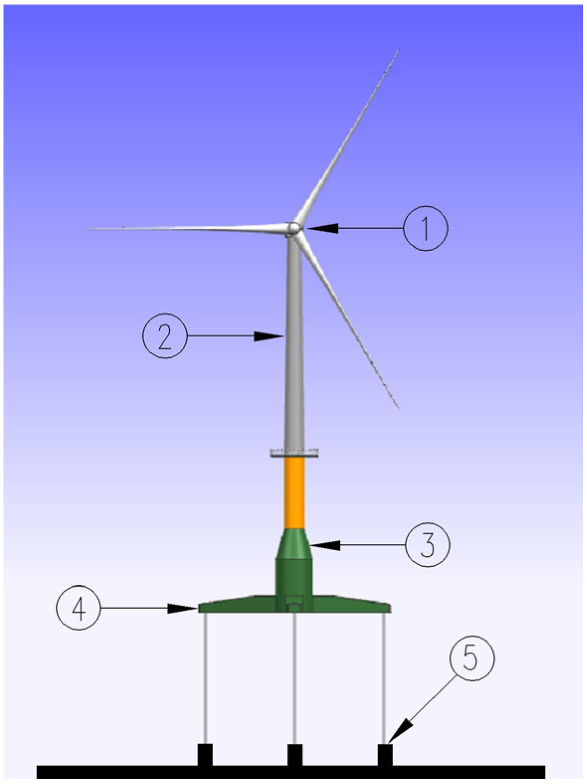
- (1)
- Rotor-Nacelle-Assembly (RNA) system;
- (2)
- Tower structure;
- (3)
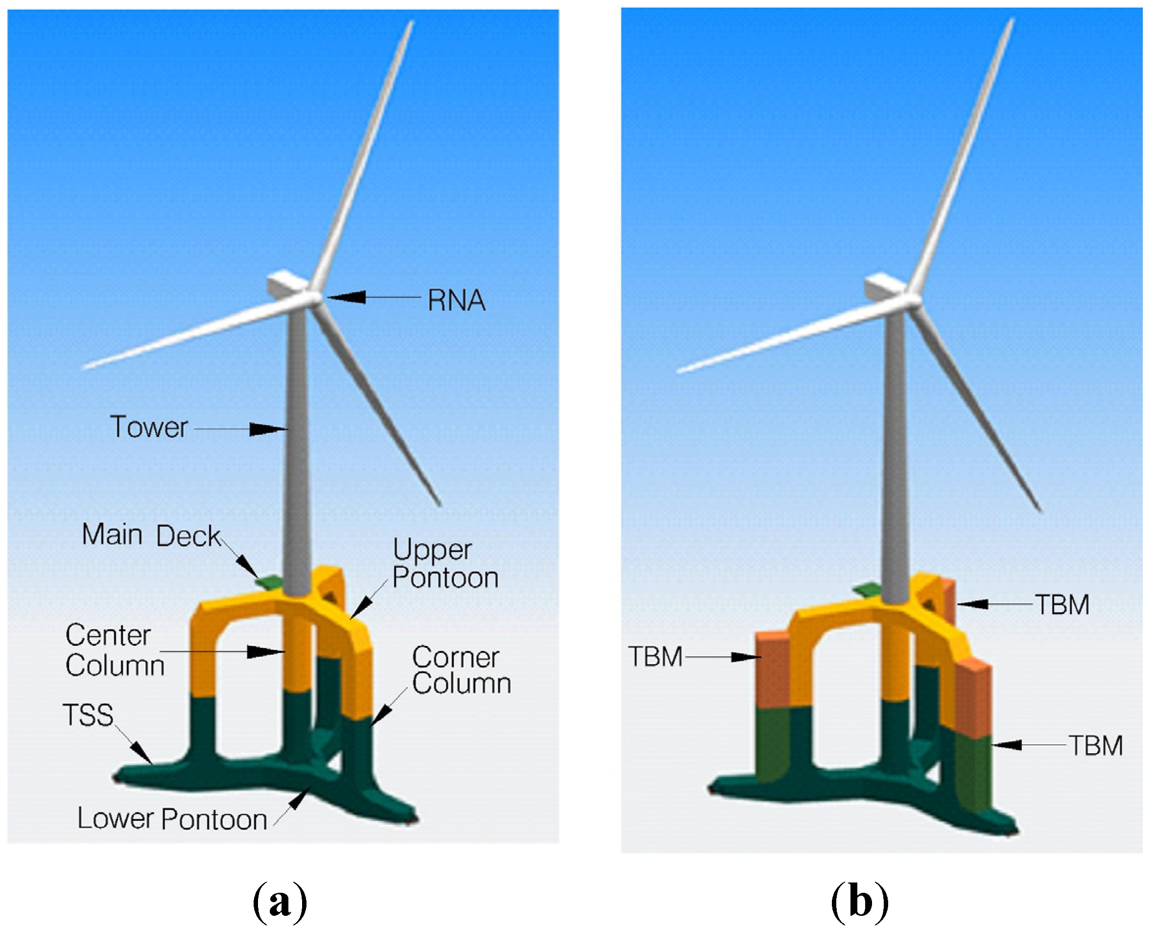
- Hull structure, consisting of columns, pontoons and column/pontoon nodes supporting the wind turbine and tendons;
- (4)
- Mooring system consisting of tendons and top/bottom connectors;
- (5)
- Foundation system consisting of templates with bottom tendon connectors and (typically) tension piles or gravity anchors.
2. Design Basis
2.1. Design Requirements
- It must be able to support a 5-MW offshore wind turbine.
- It must ensure that the high-energy excitation frequencies do not coincide with the natural frequency of the entire system.
- It must offer sufficient rigidity to the wind turbine to withstand dynamic loads during operation.
- It must operate for a design life of at least 20 years and must survive the 50-year return wind and wave loading.
- Its inclination angle must not exceed 5° during either normal operation or extreme conditions.
- The tendon tension must always be positive, and sufficient safety margins should always be maintained for the tendon force. The safety factor should be no less than 3.0.
- It must allow adequate access for maintenance.
2.2. Site Location and Environmental Conditions
2.2.1. Water Depth
2.2.2. Water Levels

| Water levels | Values |
|---|---|
| Highest still water level (HSWL) | +2.4 m MSL |
| Mean sea level (MSL) | 0 m |
| Lowest still water level (LSWL) | −2.1 m MSL |
2.2.3. Currents
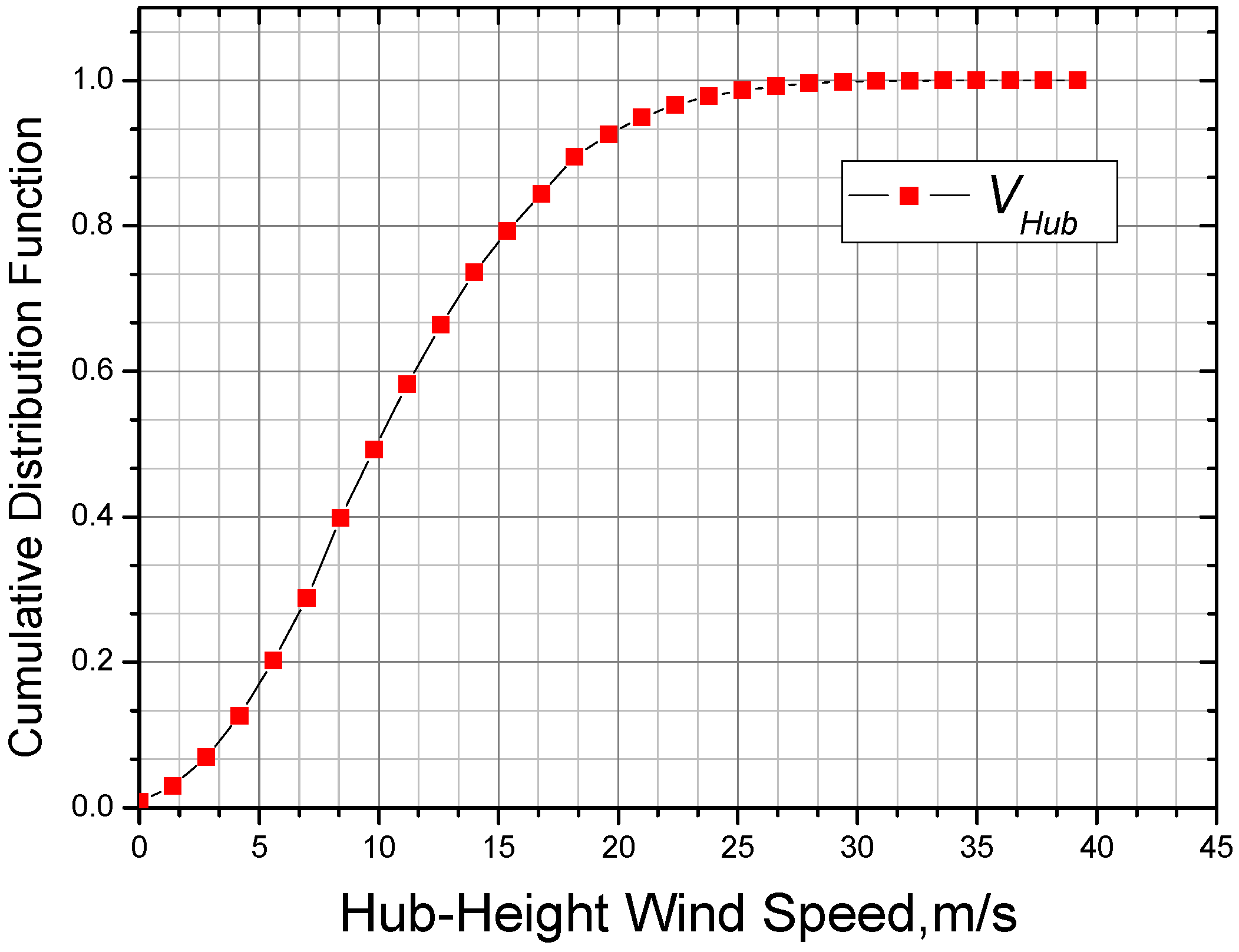
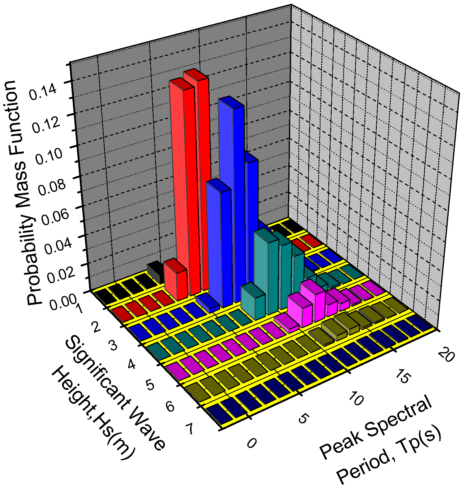
2.2.4. Wind and Wave Parameters
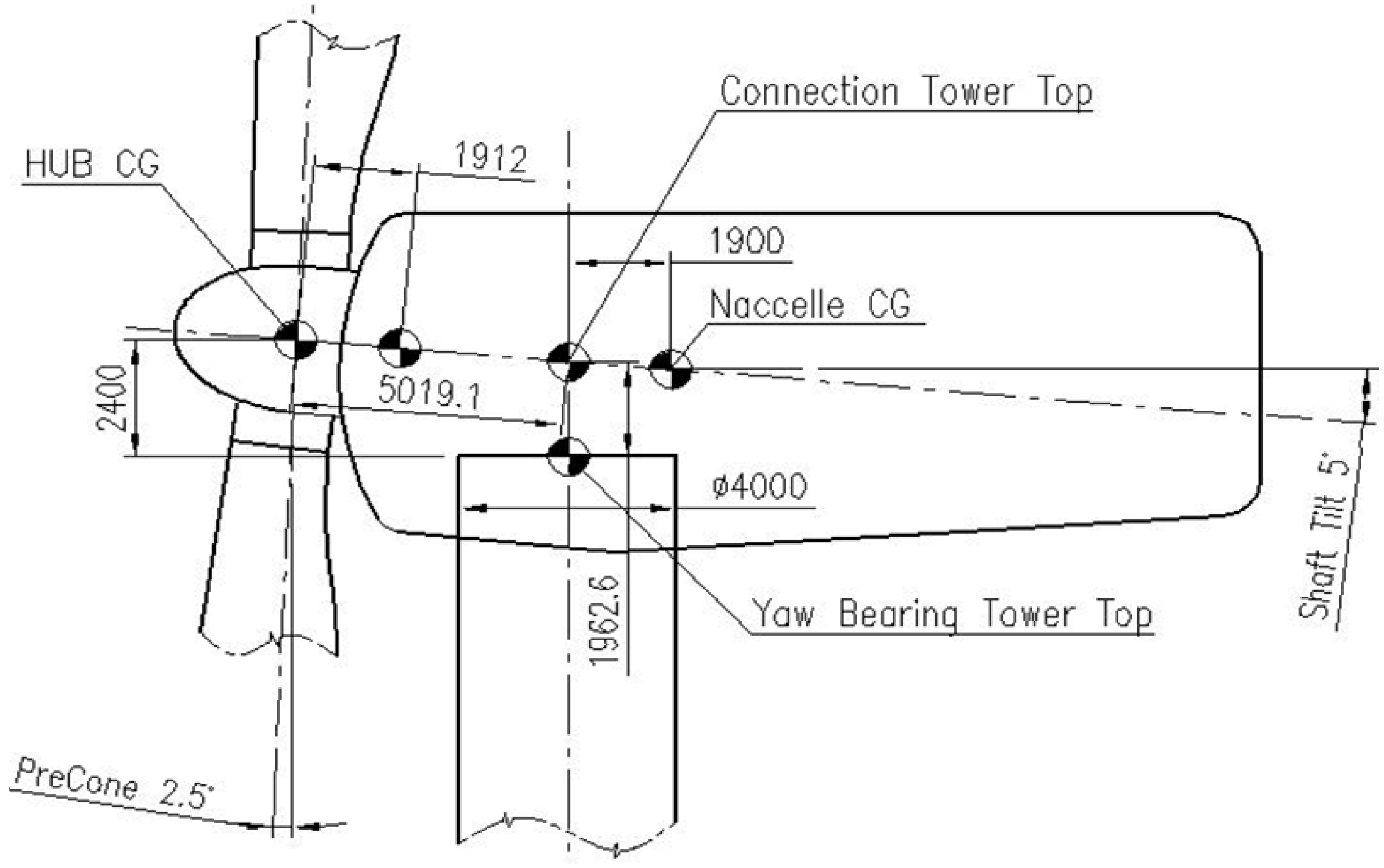
2.3. Wind Turbine RNA and Tower Specifications
| Items | Units | Specifications |
|---|---|---|
| Rotor, hub diameter | m | 126, 3 |
| Cut-in, rated, cut-out wind speed | m/s | 3, 11.4, 25 |
| Cut-in, rated rotor speed | rpm | 6.9, 12.1 |
| Overhang, shaft tilt, precone | m, deg, deg | 5, 5, 2.5 |
| Rotor mass | kg | 110,000 |
| Nacelle mass | kg | 240,000 |
| Nacelle size (length, width, height) | m | 19, 6, 7 |
| Elevation (m) | Outer Diameter (m) | Thickness (m) | Point Mass (kg) |
|---|---|---|---|
| 21.3 (Tower base) | 6.000 | 0.032 | - |
| 33.3 | 5.634 | 0.030 | - |
| 45.3 | 5.267 | 0.028 | - |
| 57.3 | 4.902 | 0.026 | 1400 |
| 69.3 | 4.537 | 0.024 | - |
| 81.3 | 4.171 | 0.022 | - |
| 86.9 (Yaw bearing) | 4.000 | 0.030 | 1000 |
3. WindStar TLP Concept Description
3.1. General Arrangement and Main Dimensions
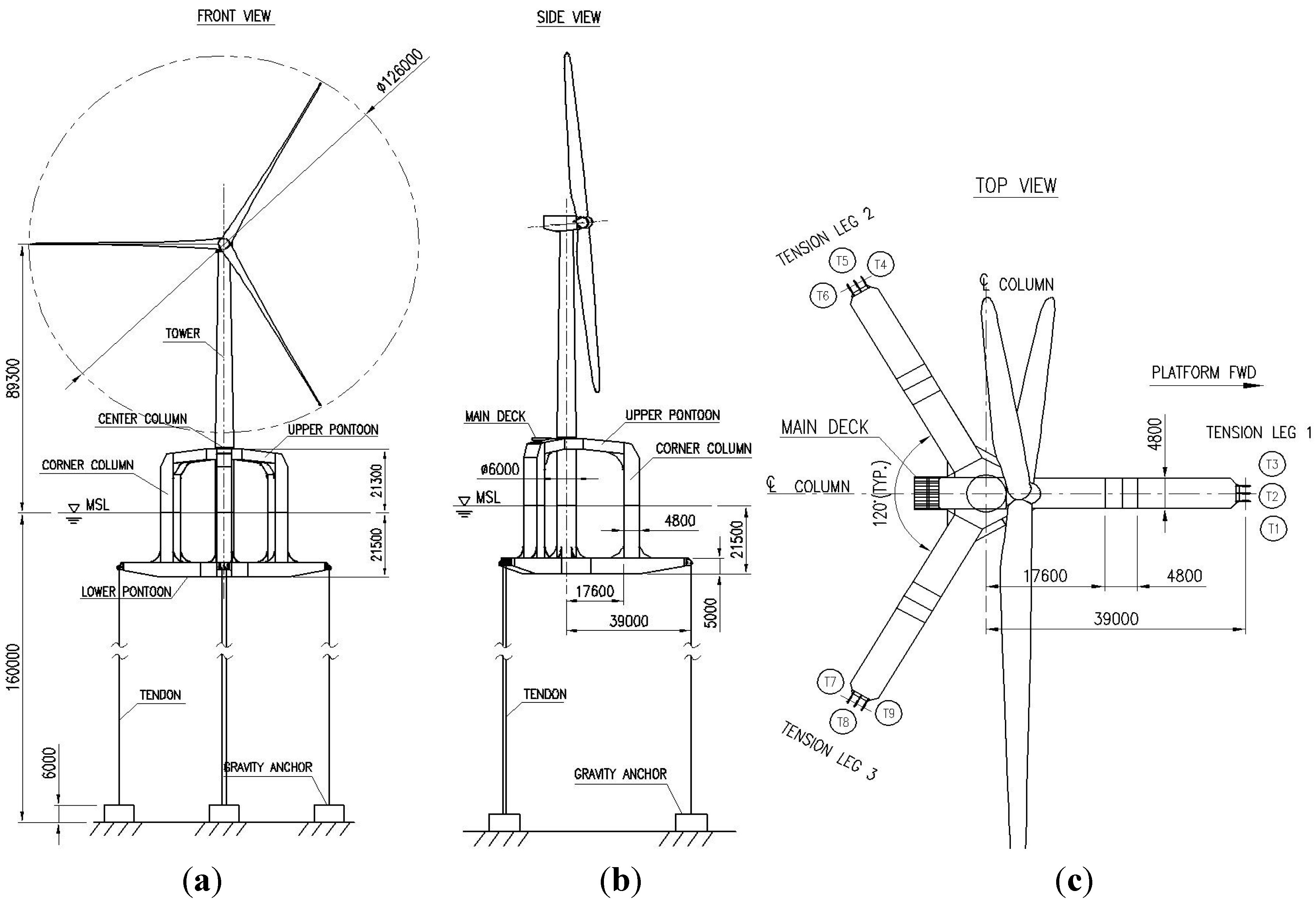
| Items | Parameters |
|---|---|
| Centre column diameter (m) | 6.0 |
| Corner column section dimension (m) | 4.8 × 4.8 |
| Distance between the centre column and corner column (m) | 20.0 |
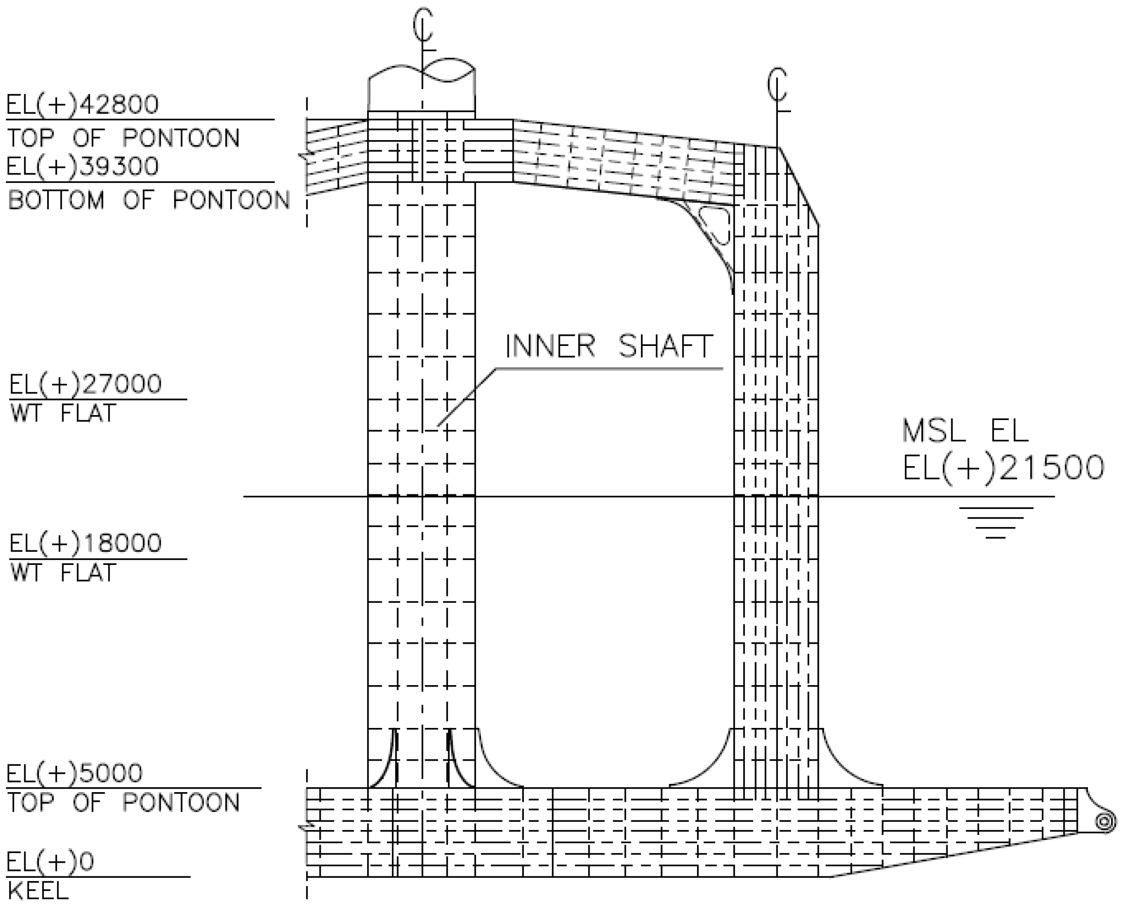
| Moulded depth (m) | 42.8 |
| Design draft (m) | 21.5 |
| Air gap distance (m) | 21.3 |
| Platform mass (including outfitting) (t) | 1770.0 |
| Platform mass vertical centre (measured from keel) (m) | 9.85 |
| Pretension (t) | 1950.0 |
| Total Displacement (t) | 4275.0 |
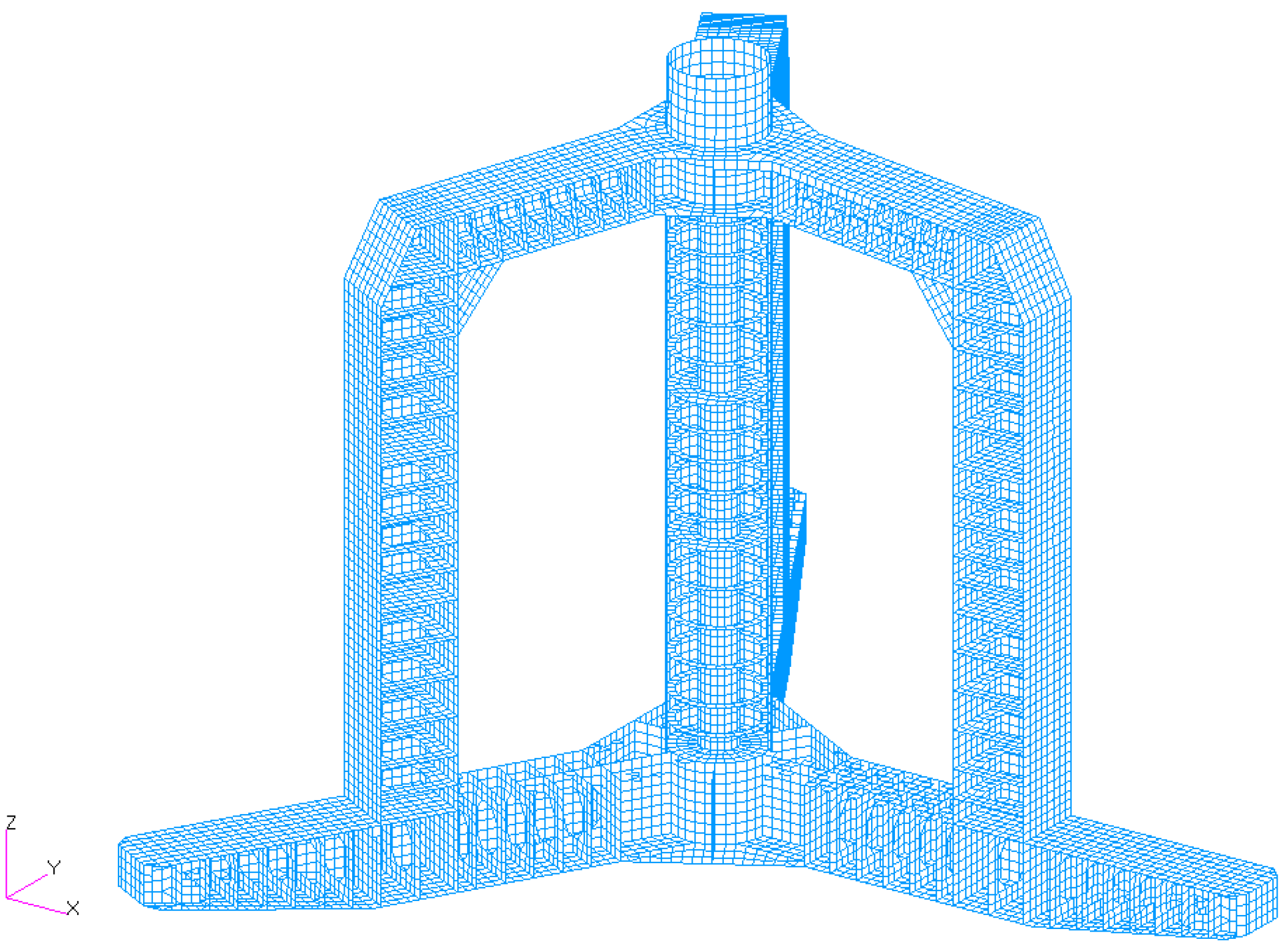
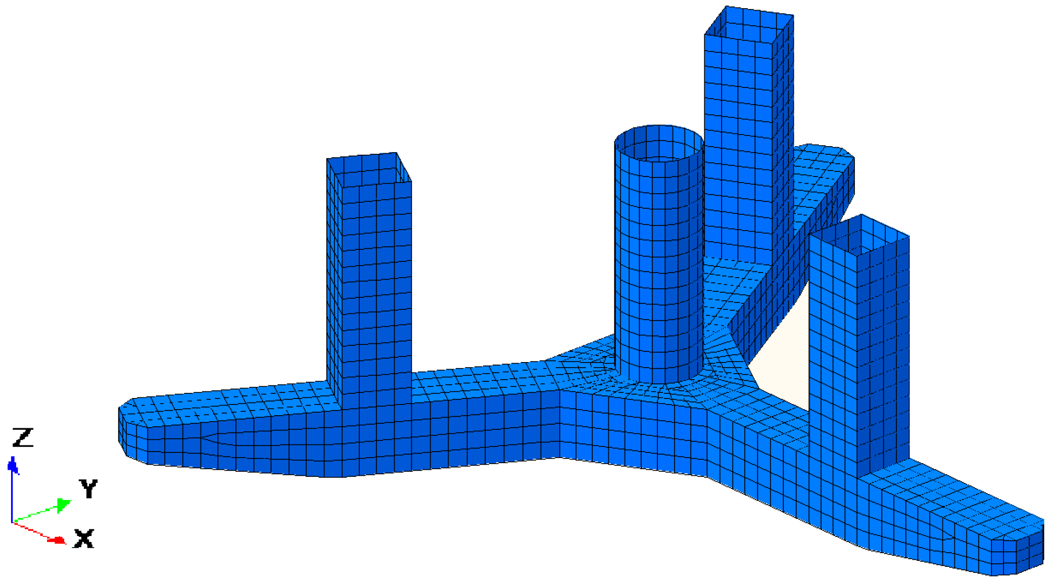
3.2. Structural Design and Weight Estimate
3.3. Mooring System Properties
| Diameter (mm) | Min. breaking load (t) | Axial stiffness EA (MN) @10%–30% MBL | Weight in air (kg/m) | Weight in water (kg/m) |
|---|---|---|---|---|
| 239.0 | 1967.0 | 372.0 | 36.1 | 9.29 |
- F tether = total pretension at the fairlead of the mooring system, 1950 t;
- L tether = total length of the tether, 134 m;
- E tether A tether = axial stiffness of the tether, 1116 MN;
- L fairlead = distance from the fairlead to the platform centre, 39 m.
| Surge (Sway) restoring coefficient C11 (kN/m) | Heave restoring coefficient C33 (kN/m) | Roll (Pitch) restoring coefficient C44 (kN.m/rad) | Yaw restoring coefficient C66 (kN.m/rad) |
|---|---|---|---|
| 145.6 | 2.5 × 10⁴ | 1.9 × 10⁷ | 2.67 × 10⁵ |
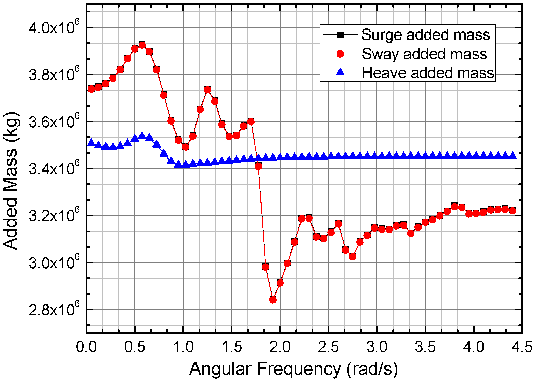
4. Hydrodynamic Characteristics
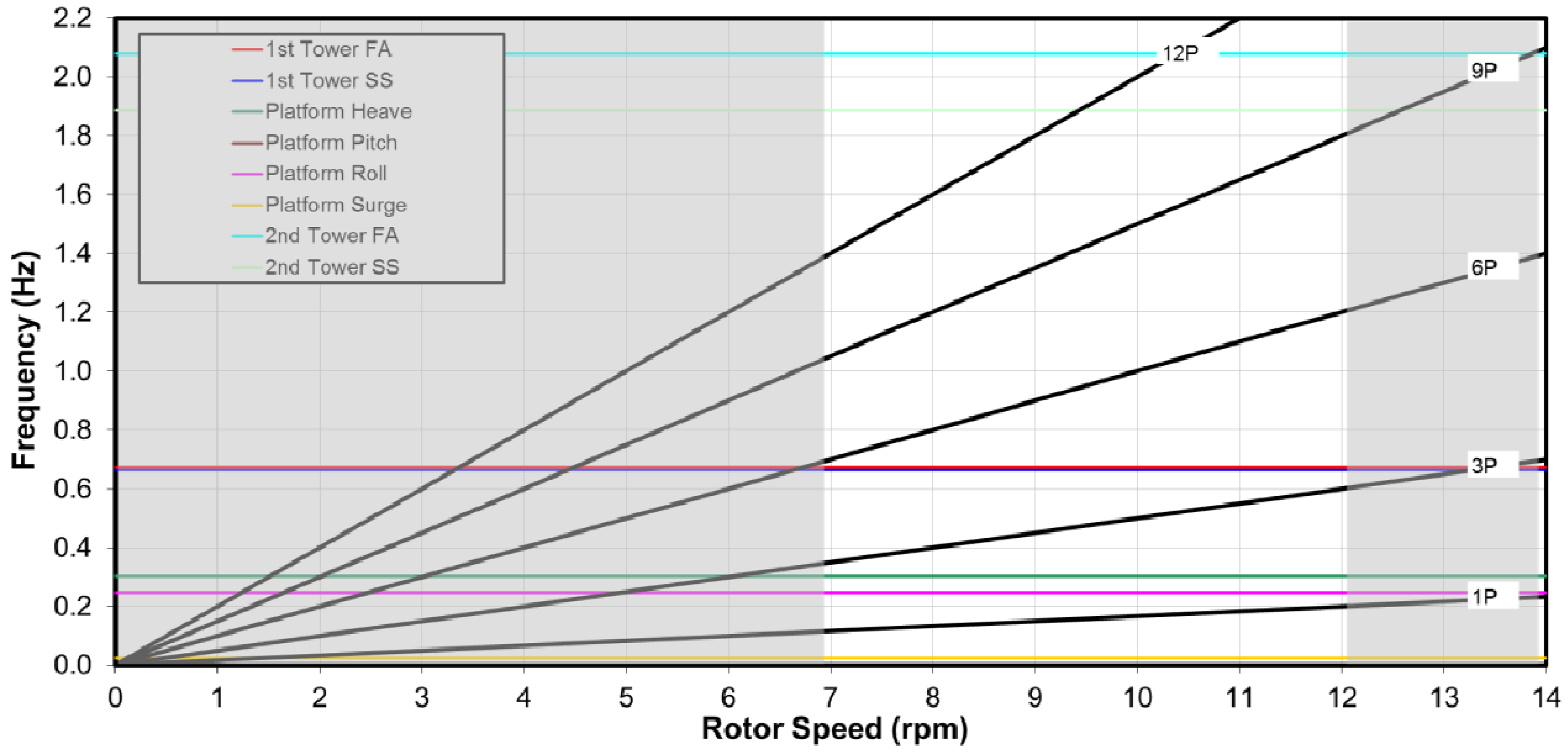
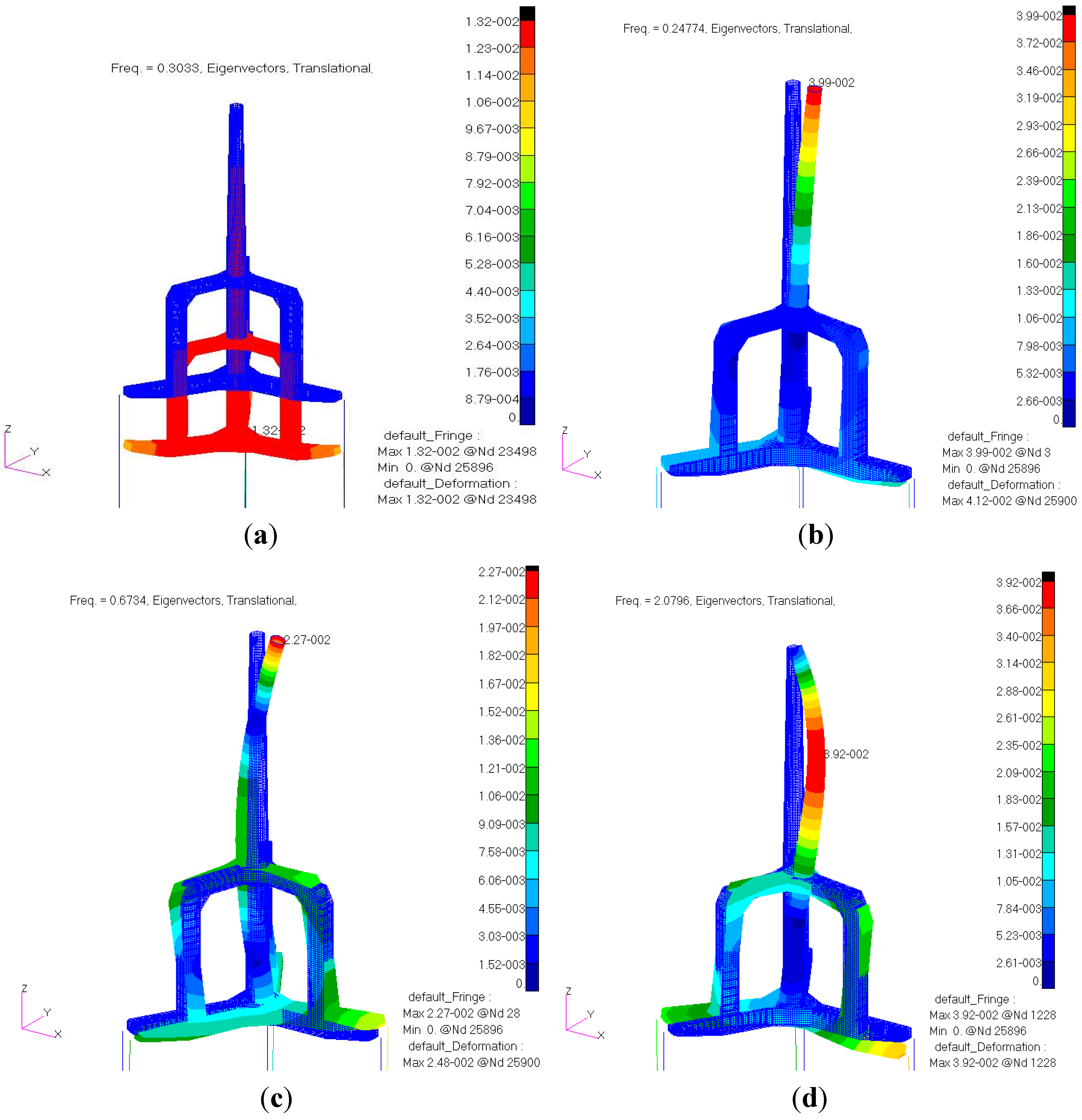
5. Natural Frequency Analysis
| Mode | Natural Frequency (Hz) |
|---|---|
| Platform Surge/Sway | 0.024 |
| Platform Yaw | 0.049 |
| Platform Heave | 0.303 |
| Platform Pitch | 0.248 |
| Platform Roll | 0.247 |
| 1st Tower Side-Side | 0.664 |
| 1st Tower Fore-Aft | 0.673 |
| 2nd Tower Side-Side | 1.886 |
| 2nd Tower Fore-Aft | 2.079 |
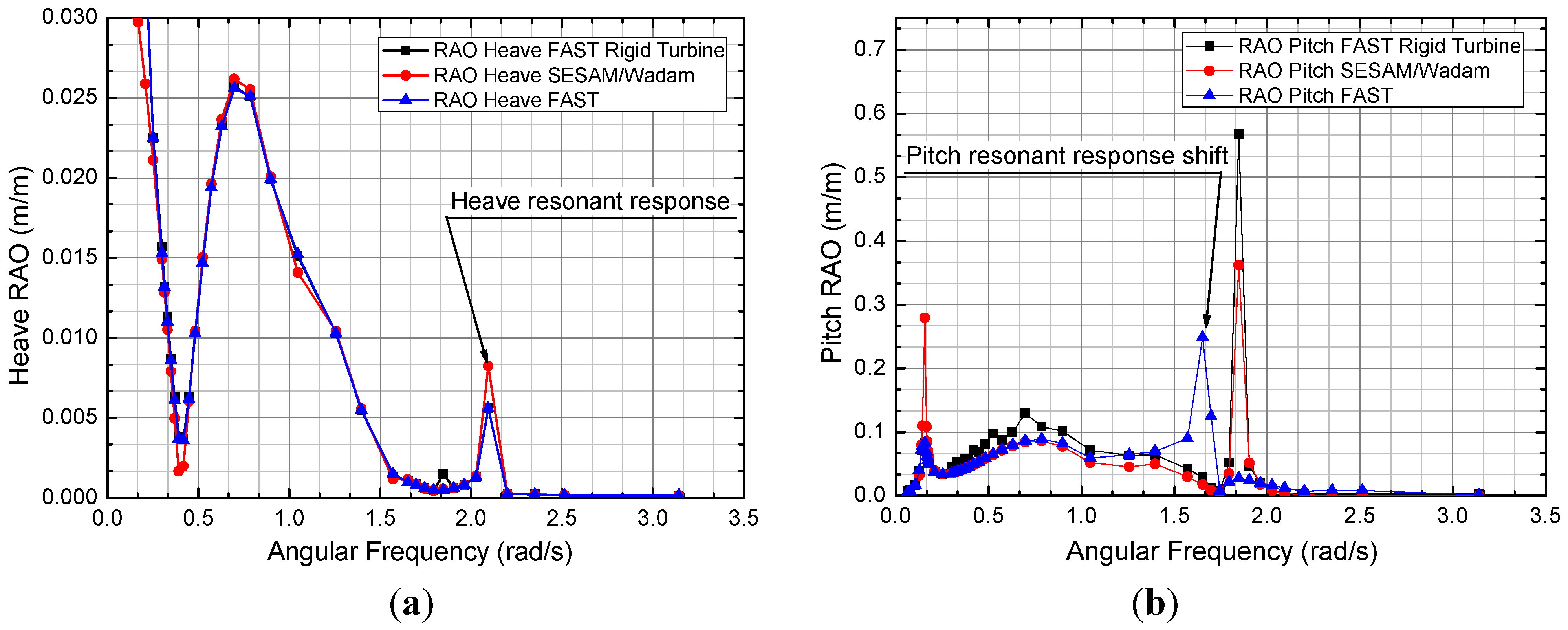
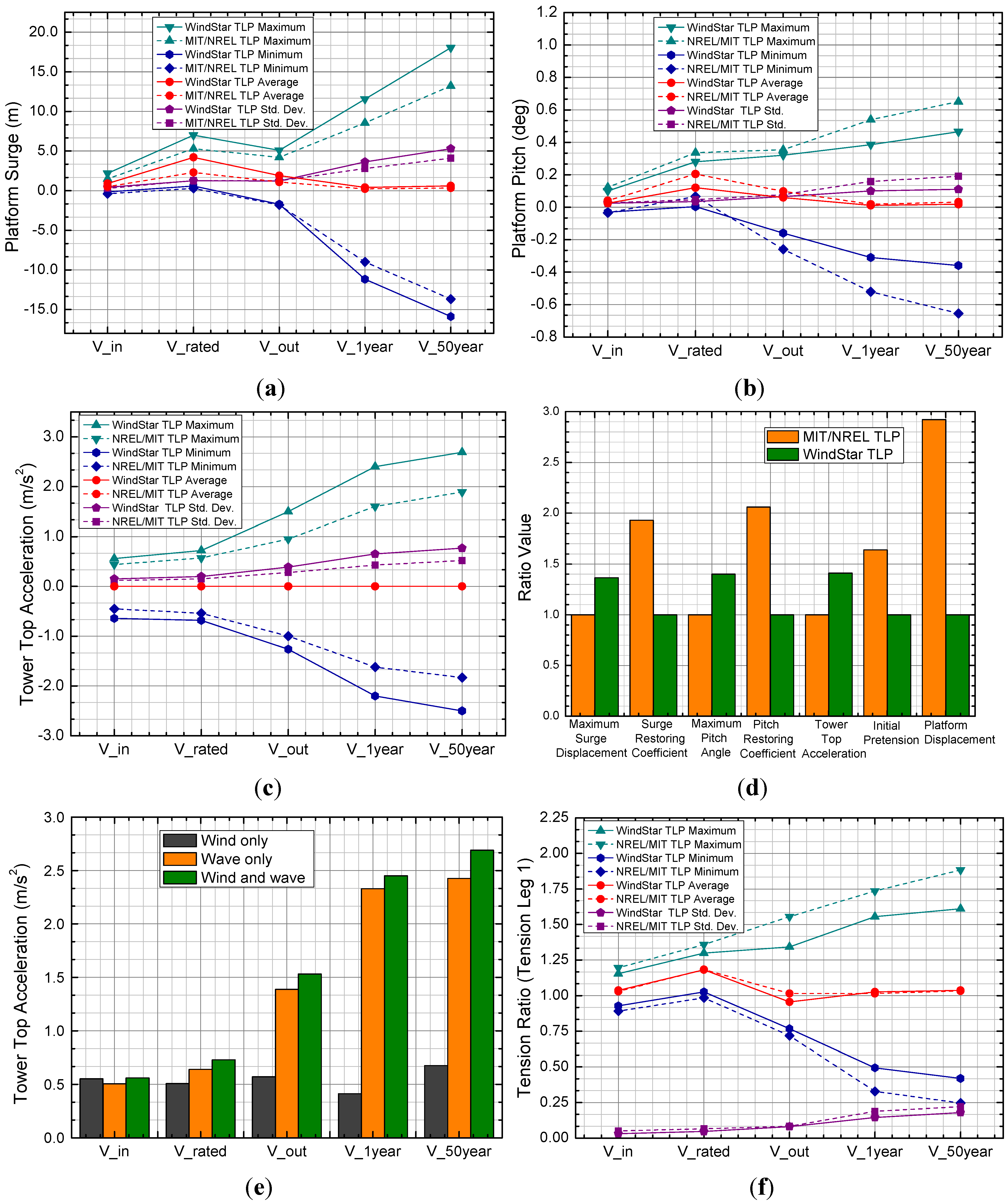
6. Dynamic Response Simulations
| DLC | Winds | Waves | Currents | Events | ||
|---|---|---|---|---|---|---|
| Model | Speed | Model | Height | Model | ||
| 1.3 | ETM | Vin < Vhub < Vout | NSS | HS = E[HS|Vhub] | NCM | Normal operation |
| 6.1a | EWM | Vhub = 0.95 × V50 | ESS | HS = 1.09 × HS50 | ECM | Yaw = 0° |
| 6.3a | EWM | Vhub = 0.95 × V1 | ESS | HS = 1.09 × HS1 | ECM | Yaw = 0° |
7. Conclusions
Acknowledgements
References
- Robertson, A.; Jonkman, J.M. Loads Analysis of Several Offshore Floating Wind Turbine Concepts; Technical Report NREL/TP-5000-50539; National Renewable Energy Laboratory: Golden, CO, USA, 2011. [Google Scholar]
- Henderson, A.R.; Witcher, D.; Morgan, C.A. Floating support structures enabling new markets for offshore wind energy. In Proceedings of the European Wind Energy Conference, Marseille, France, 16–19 March 2009.
- Wang, C.M.; Utsunomiya, T.; Wee, S.C.; Choo, Y.S. Research on Floating wind turbines: A literature survey. IES J. Part A Civil Struct. Eng. 2010, 3, 267–277. [Google Scholar] [CrossRef]
- Cordle, A. State-of-the-art in design tools for floating offshore wind turbines. 2010. Available online: http://www.upwind.eu/pdf/UpWind_WP4_D4.3.5_Floating%20design%20tools.pdf (accessed on 25 July 2012).
- Nielsen, F.G.; Hanson, T.D.; Skaare, B. Integrated dynamic analysis of floating offshore wind turbine. In Proceedings of OMAE 25th International Conference on Offshore Mechanics and Arctic Engineering, Hamburg, Germany, 4–9 June 2006.
- Roddier, D.; Cermelli, C.; Aubault, A.; Weinstein, A. WindFloat: A floating foundation for offshore wind turbines. J. Renew. Sustain. Energy 2010, 2, 104–138. [Google Scholar] [CrossRef]
- Suzuki, K.; Yamaguchi, H.; Akase, M.; Imakita, A.; Ishihara, T.; Fukumoto, Y.; Oyama, T. Initial design of tension leg platform for offshore wind farm. J. Fluid Sci. Technol. 2011, 6, 372–381. [Google Scholar] [CrossRef]
- Ren, N.; Li, Y.; Ou, J. The effect of additional mooring chains on the motion performance of a floating wind turbine with a tension leg platform. Energies 2012, 5, 1135–1149. [Google Scholar] [CrossRef]
- Matha, D. Model Development and Load Analysis of an Offshore Wind Turbine on a Tension Leg Platform, with a Comparison to Other Floating Turbine Concepts; Technical Report NREL/SR-500-45891; National Renewable Energy Laboratory: Golden, CO, USA, 2010. [Google Scholar]
- Moon, W.L., III; Nordstrom, C.J. Tension leg platform turbine: A unique integration of mature technologies. In Proceedings of the 16th Offshore Symposium, Houston, TX, USA, 9 February 2010.
- Jonkman, J.M. Dynamics Modeling and Loads Analysis of an Offshore Floating Wind Turbine. Ph.D. Thesis, University of Colorado, Boulder, CO, USA, 2007. [Google Scholar]
- Jonkman, J.M.; Matha, D. Dynamics of offshore floating wind turbines-analysis of three concepts. Wind Energy 2011, 14, 557–569. [Google Scholar] [CrossRef]
- Fischer, T.; de Vries, W.; Schmidt, B. Upwind design basis. 2010. Available online: http://www.upwind.eu/pdf/WP4_DesignBasis.pdf (accessed on 11 August 2012).
- IEC Technical Committee 88. Wind Turbines—Part 3: Design Requirements for Offshore Wind Turbines; Technical Report 61400-3 ed.1.0; IEC: Geneva, CH, USA, 2008.
- Jonkman, J.; Butterfield, S.; Musial, W.; Scott, G. Definition of a 5-MW Reference Wind Turbine for Offshore System Development; Technical Report NREL/TP-500-38060; National Renewable Energy Laboratory: Golden, CO, USA, 2009. [Google Scholar]
- American Petroleum Institute. Bulletin on Stability Design of Cylindrical Shells, 3rd ed.; American Petroleum Institute (API): Washington, DC, USA, 2004. [Google Scholar]
- American Bureau of Shipping. Rules for Building and Classing Mobile Offshore Drilling Units, Part 3: Hull Construction and Equipment; American Bureau of Shipping (ABS): Houston, TX, USA, 2012. [Google Scholar]
- Bexco n.v. Polyester and Dyneema® Mooring Ropes Manual. 2004. Available online: http://www.offshoremoorings.org/moorings/Downloads/deepropemanual.pdf (accessed on 12 August 2012).
- Withee, J.E. Fully Coupled Dynamic Analysis of a Floating Wind Turbine System. Ph.D. Thesis, Massachusetts Institute of Technology, Cambridge, MA, USA, 2004. [Google Scholar]
- Det Norske Veritas. Wave Analysis by Diffraction and Morison Theory (WADAM); SESAM User’s Manual, Det Norske Veritas (DNV): Høvik, Norway, 1994. [Google Scholar]
- Jonkman, J.M.; Buhl, M.L., Jr. FAST User’s Guide; Technical Report NREL/EL-500-38230; National Renewable Energy Laboratory: Golden, CO, USA, 2005. [Google Scholar]
- Bae, Y.H.; Kim, M.H.; Im, S.W. Effects of tower elasticity and aero-loading in aero-elastic-control-floater-mooring coupled dynamic analysis for a TLP-type FOWT. In Proceedings of the Twenty-second International Offshore and Polar Engineering Conference, Rhodes, Greece, 17–22 June 2012.
- Grant, S. MSC/NASTRAN Basic Dynamic Analysis User’s Guide; The MacNeal Schwendler Corporation: Los Angeles, CA, USA, 1997; pp. 36–86. [Google Scholar]
- Jonkman, B.J.; Buhl, M.L., Jr. TurbSim User’s Guide; Technical Report NREL/TP-500–41136; National Renewable Energy Laboratory: Golden, CO, USA, 2007. [Google Scholar]
© 2012 by the authors; licensee MDPI, Basel, Switzerland. This article is an open access article distributed under the terms and conditions of the Creative Commons Attribution license (http://creativecommons.org/licenses/by/3.0/).
Share and Cite
Zhao, Y.; Yang, J.; He, Y. Preliminary Design of a Multi-Column TLP Foundation for a 5-MW Offshore Wind Turbine. Energies 2012, 5, 3874-3891. https://doi.org/10.3390/en5103874
Zhao Y, Yang J, He Y. Preliminary Design of a Multi-Column TLP Foundation for a 5-MW Offshore Wind Turbine. Energies. 2012; 5(10):3874-3891. https://doi.org/10.3390/en5103874
Chicago/Turabian StyleZhao, Yongsheng, Jianmin Yang, and Yanping He. 2012. "Preliminary Design of a Multi-Column TLP Foundation for a 5-MW Offshore Wind Turbine" Energies 5, no. 10: 3874-3891. https://doi.org/10.3390/en5103874