Article

Measurement and Evaluation of Heating Performance of Heat Pump Systems Using Wasted Heat from Electric Devices for an Electric Bus

Korea Automotive Technology Institute, 74 Yongjung-Ri, Pungse-Myun, Dongnam-Gu, Chonan-Si 330-912, Korea
*
Author to whom correspondence should be addressed.
Energies 2012, 5(3), 658-669; https://doi.org/10.3390/en5030658
Submission received: 9 January 2012 / Revised: 17 February 2012 / Accepted: 4 March 2012 / Published: 8 March 2012

Abstract

:
The objective of this study is to investigate heating performance characteristics of a coolant source heat pump using the wasted heat from electric devices for an electric bus. The heat pump, using R-134a, is designed for heating a passengers’ compartment by using discharged energy from the coolant of electric devices, such as motors and inverters of the electric bus. The heating performance of the heat pump was tested by varying the operating parameters, such as outdoor temperature and volume flow rate of the coolant water of the electrical devices. Heating capacity, compressor work, and heating COP were measured; their behaviors with regard to the parameters were observed. Experimental results showed that heating COP increased with decrease of outdoor temperature, from 20.0 °C to 0 °C, and it observed to be 3.0 in the case of 0 °C outdoor temperature. The observed characteristics of the heating COP suggest that the heat pump is applicable as the cabin heater of an electric vehicle, which is limited by short driving range.

Nomenclature

CpSpecific heat, (kJ kg−1 K−1) Q ˙ Capacity or work, (kW)
COPCoefficient of performanceTTemperature, (°C, K)
hEnthalpy, (kJ kg−1)
Subscripts
compcompressorppressure
ininletrefrefrigerant
outoutletwwater (wet)

1. Introduction

In recent years, concerns have been focused on the international issues of shocking oil price increases, considering the depletion of fossil fuel energy that has resulted from industrialization. Moreover, consumption of fossil fuel energy leads to environmental pollution, including air pollution, acid rain, global warming due to the carbon dioxide, and destruction of the ozone layer. The increase in automobile usage makes these problems even more severe. Considering this situation, studies on effective use of energy and exploration of how to produce less exhaust gas in automobiles become necessary. Automobile manufacturers are looking for alternatives, like hybrid vehicles, fuel cell electric vehicles, and electric vehicles. In these vehicles, the passenger cabin heating has a considerable impact on fuel economy, especially during the waiting periods, as does cooling. Heating then becomes a particularly important issue because of the decreased engine waste heat compared to conventional vehicles. Therefore, performance and improvement of the heating system for passenger cabin heating is vital for energy savings in the abovementioned automobiles. In heating conditions for passengers in alternative vehicles, without internal combustion engines, the heat pump uses discharged energy from electric devices such as a motor, a battery, or an inverter of the electric vehicle; these are possibilities for shorter heating warm-up. Therefore, the heat pump has the advantage of providing heating to the vehicle without an international combustion engine.
The performance characteristics of the heat pump, using R-134a, have been extensively investigated. Park et al. [1] studied the development of heat pump systems for high-efficiency engine vehicles. They estimated the feasibility of the R-134a automobile air conditioning system using a heat pump in the diesel engine. Lawrence et al. [2] compared the on-vehicle performance of R-152a and R-134a heat pumps using an engine coolant. They reported that the performance and capacity for both R-152a and R-134a heat pumps are almost identical. Shin et al. [3] reported the application of R-134a heat pumps for buses by using an engine coolant as the heat source, based on the retrofitting of a roof mounted air conditioning system. They found that the roof mounted heat pump could provide superior heating performance for the passenger compartment, using the engine coolant as a heat source instead of using conventional heating systems.
Extensive studies have been conducted on heat pumps, using R-134a, for conventional automobiles and buses with internal combustion engines. However, studies of the performance characteristics of the coolant source heat pump using wasted heat of electric devices for an electric bus in heating mode are rare. The objective of this study was to investigate the heating performance characteristics of the heat pump, using the wasted heat of electric devices, for an electric bus by varying the outdoor temperature and volume flow rate for a condenser and an evaporator. In addition, the coolant source heat pump was designed for heating the cabin of an electric bus in the absence of an exhaust heat source with a relatively high temperature such as that of internal combustion engine vehicles.

2. Experimental Design and Data Reduction

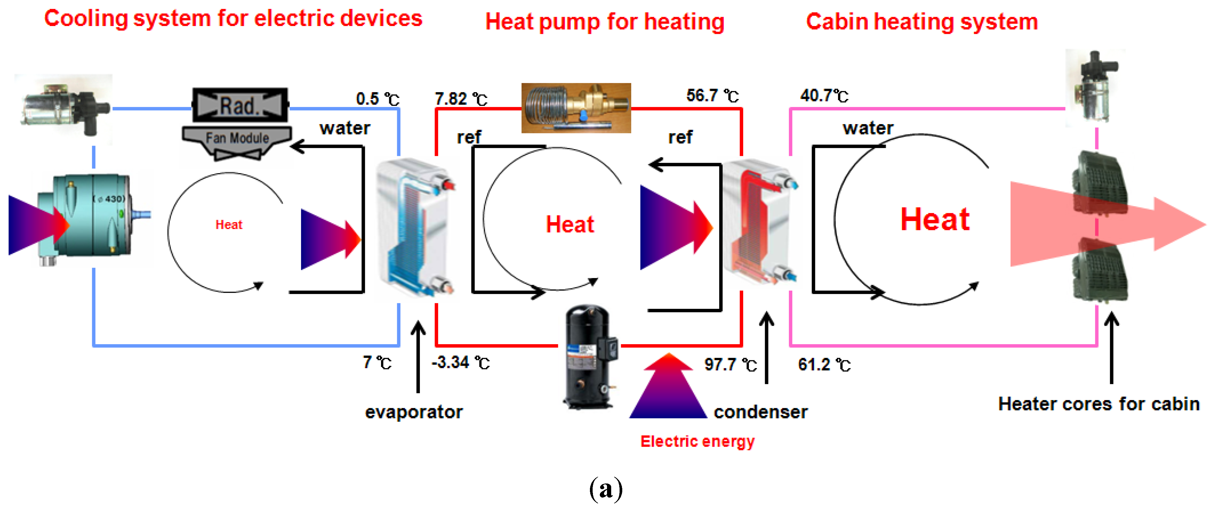
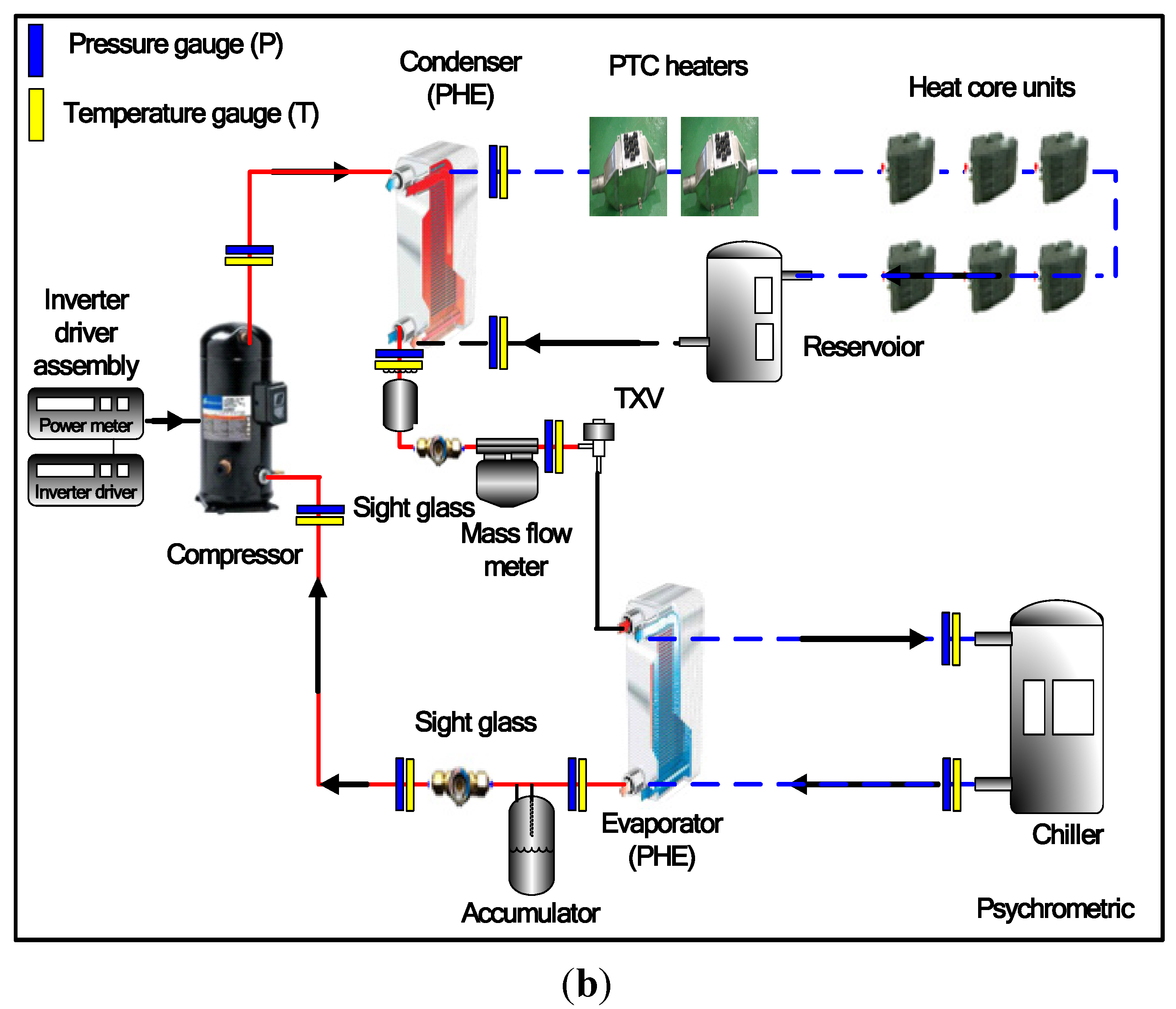
2.1. Test Setup and Design

Figure 1(a) shows the heat transfer mechanism of the heat pump using the wasted heat of electric devices for an electric bus under outdoor temperatures of 0~−10 °C (normally, cold weather conditions of autumn and winter). The water inlet temperature of the evaporator side considered 7 °C because the water temperatures could be obtained between 5 and 15 °C by using the wasted heat from the electronic devices at given outdoor temperatures. The wasted heat from the electric devices (mainly, inverter driver and traction motor) comprised of an electric bus is used to improve the heating capacity of the heat pump. Then, the heated coolant at the condenser side of the heat pump was utilized to heat the air in the cabin by using the heater cores in the cabin of electric bus. The coolant source heat pump for heating in this study was designed to make maximum use of the exhaust heat from electric devices such as motors, inverter drivers, controllers, etc. Finally, the water temperature of the condenser outlet showed 61.2 °C at given conditions. Figure 1(b) shows the schematic diagram of the basic experimental setup of measuring the heating performance of the coolant source heat pump using a coolant of electric devices.
Figure 1. Heat transfer mechanism and schematic diagram of the experimental setup. (a) Heat transfer mechanism; (b) Schematic diagram.
Energies 05 00658 g001aEnergies 05 00658 g001b
This test facility consisted primarily of the water to air heater core system and a refrigerant to water heat pump composed of a refrigerant loop, air circulation loop, and coolant loop, using the wasted heat from electric devices. The test setup consisted primarily of the scroll compressor, plate heat exchangers (condenser and evaporator), an expansion device (TXV), and heater cores for indoor heating of the bus, accumulator, and receiver. Table 1 lists the specifications of the heat pump used in this study.
Table 1. Specifications of the components of the heat pump.
ComponentsSpecifications
Compressor (displacement rate)Scroll type, 0.1453 m3/s
Condenser (material, size)Plate heat exchanger, (Alloy 316, Ref/water: 3.040/3.135 dm3)
Evaporator (material, size)Plate heat exchanger, (Alloy 316, Ref/water: 2.470/2.565 dm3)
Expansion devicesThermostatic expansion valve (TXV)
Heater core (Size)Overall size = 320.0 × 194.0 × 37.0 mm3,
(Core size = 265.0 × 193.0 × 29.0 mm3)
Maximum voltage = 27.5 V, Currents = 4.0 A~2.5 A,
Maximum volume flow rate = 8.3 m3/min
The test setup was installed in a psychrometric calorimeter to provide pre-controlled ambient temperature. The psychrometric calorimeter, equipped with an air-handling unit including a cooling coil, a heating coil, and a humidifier, was set to 0 °C, 10.0 °C, 20.0 °C to an accuracy of ±0.2 °C. Tests were performed at 20.0 °C of the outdoor temperature in order to check the normal operation of the tested heat pump and compare it to the heating performance results of other conditions. The psychrometric calorimeter was controlled by using a PID control method. The compressor frequency was fixed at 60.0 Hz and the current used to drive the compressor was measured by the inverter driver (SV-IG5A) manufactured by LS industrial systems. The compressor motor is rated as 12.0 kW at 60.0 Hz and the displacement of the compressor is 0.1453 m3/s. The compressor work was calculated by a power input and a current. The compressor work input was measured by a power meter with an uncertainty of ±0.2%. In addition, the power input was measured to evaluate the heat pump using R-134a. In this study, the installed electric compressor using the inverter driver was chosen by matching the required heating and cooling capacity of the heat pump for an electric bus. Both the evaporator and condenser were plate heat exchanger types for the purpose of exchanging the heat between the refrigerant and the coolant source, using wasted heat of electric devices. The heater core was an overall size of 320.0 × 194.0 × 37.0 mm3 and a core size of 265.0 × 193.0 × 29.0 mm3. The heater core was operated in the rating maximum voltage of 27.5 V (DC), with allowable current ranging from 4.0 A to 2.5 A and a maximum volume flow rate of 8.3 m3/min. During experiments, major operating parameters were monitored graphically and numerically in real time. To calculate and evaluate the performance of the heat pump cycle, temperatures, pressures, and mass flow rates were measured. In addition, the power input was measured precisely in order to evaluate the heat pump using R-134a. Table 2 shows test conditions used in this study. During experiments, the outdoor air temperature was set to 0, 10.0, 20.0 °C. Water flow rates for condenser and evaporator sides varied from 0.015 m3/min to 0.025 m3/min and 0.035 m3/min to 0.050 m3/min respectively. Each experiment measured after air temperature and water flow rates were completely stable. The tested conditions in Table 2 were chosen for describing the required heating capacity in the winter and autumn seasons.
Table 2. Test conditions.
ItemsConditions
Outdoor air temperature (°C)0, 10.0, 20.0
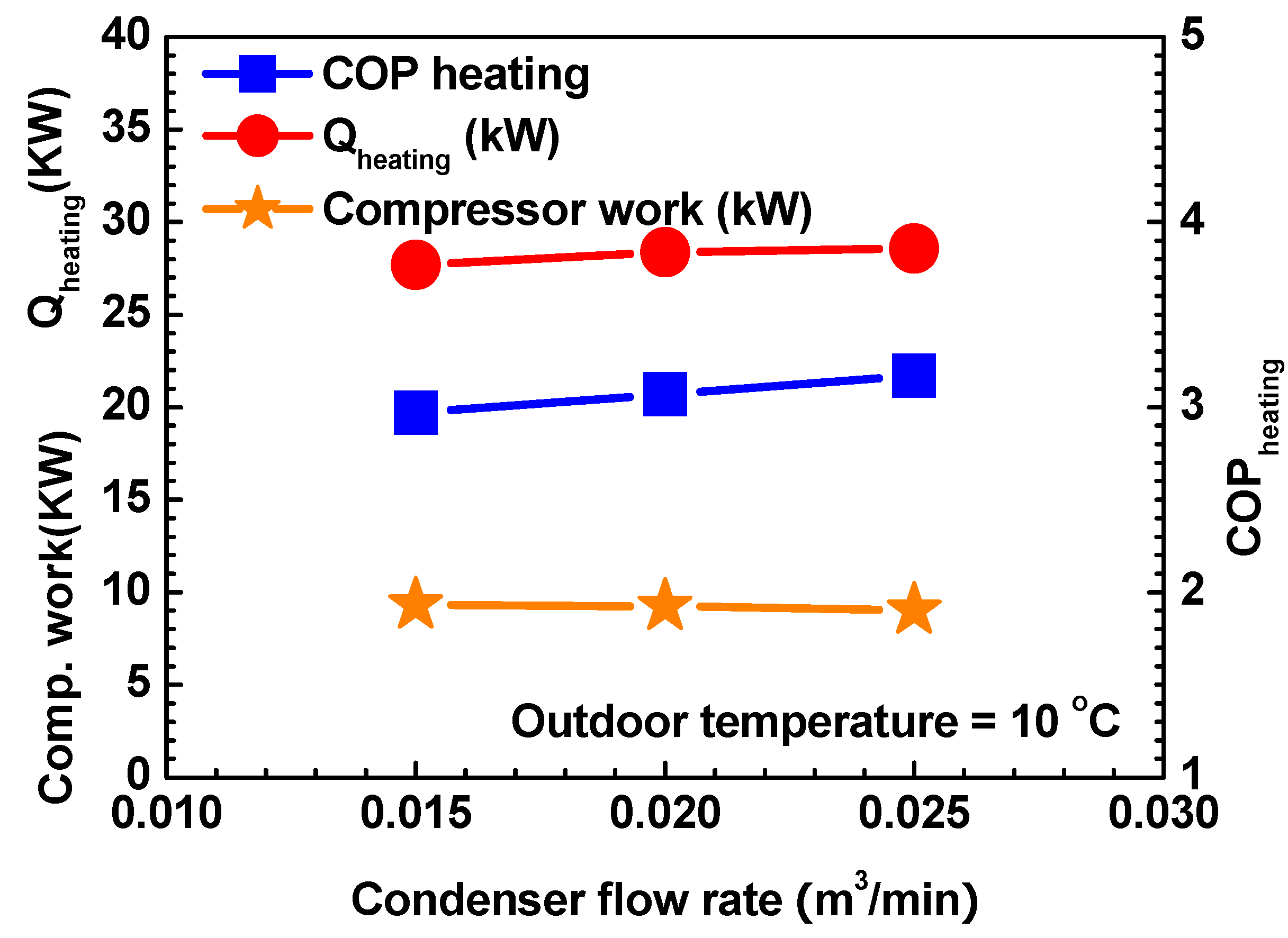
Water flow rate for condenser side (m3/min )0.015, 0.020, 0.025
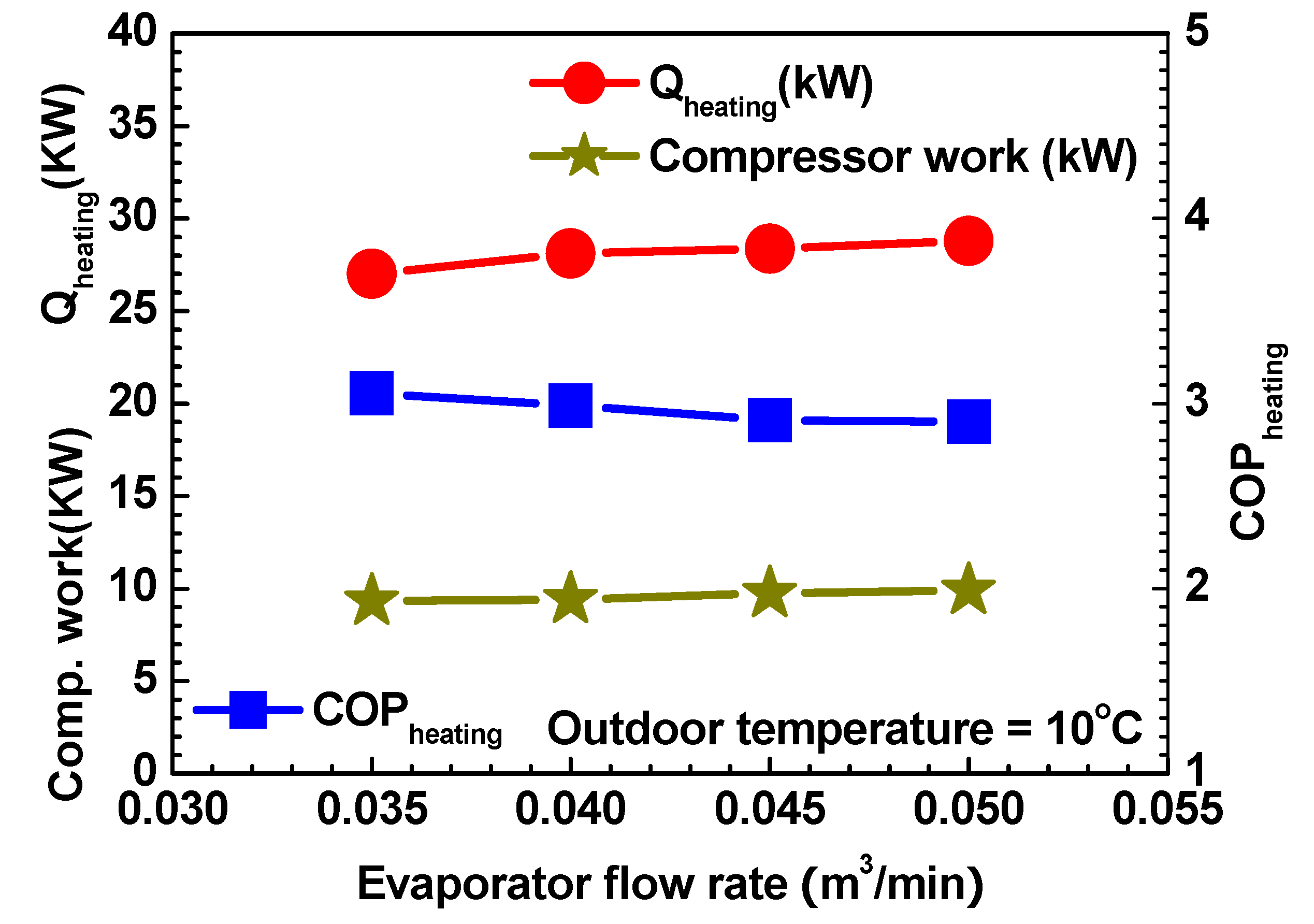
Water flow rate for evaporator side (m3/min )0.035, 0.040, 0.045, 0.050
RefrigerantR-134a
Working fluidWater
However, the outdoor air temperature was tested at over 0 °C because of the working fluid of the water. In next paper, heating performances of the heat pump in extremely cold weather conditions under 0 °C will be considered with ethylene glycol-water mixture as a working fluid. Table 3 shows the uncertainties of the measured parameters. Refrigerant and water temperatures were measured with thermocouples. The thermocouples were calibrated to an accuracy of ±0.1 °C. Pressures were measured using a pressure transducer with an uncertainty of 1.0%. The refrigerant mass flow rate was measured using a Coriolis type flow meter with an uncertainty of ±0.2% of reading.
Table 3. Uncertainties of the measured and reduced parameters.
ItemsConditions
Temperature±0.1 °C
Mass flow rate±0.2%
Pressure1.0%
Heating capacity±3.72%
Power input±0.2%
COP±3.73%

2.2. Data Reduction

The refrigerant side capacity was calculated by the refrigerant enthalpy method [4,5]. The heating capacity for the water side was determined by utilizing the water flow rate, and enthalpy difference was calculated by Equations (1) and (2), because single-phase liquid was used as the working fluid:
Q ˙ r e f = m ˙ r e f Δ h r e f
Q ˙ w = m ˙ w C p , w ( T w , i n T w , o u t )
The water side capacity was consistent with the refrigerant capacity, within 5.0%, so the present experimental setup was found to be appropriate. The heating COP (coefficient of performance) of the heat pump for heating was calculated by Equation (3):
C O P = Q w W c o m p
The uncertainty of the power input, heating COP and heating capacity were determined to be 0.2%, ±3.73%, and ±3.72%, respectively, using the method suggested by Moffat [6]. In addition, the transient state performances for cabin heating were estimated with the above-mentioned steady state performances.

3. Results and Discussion

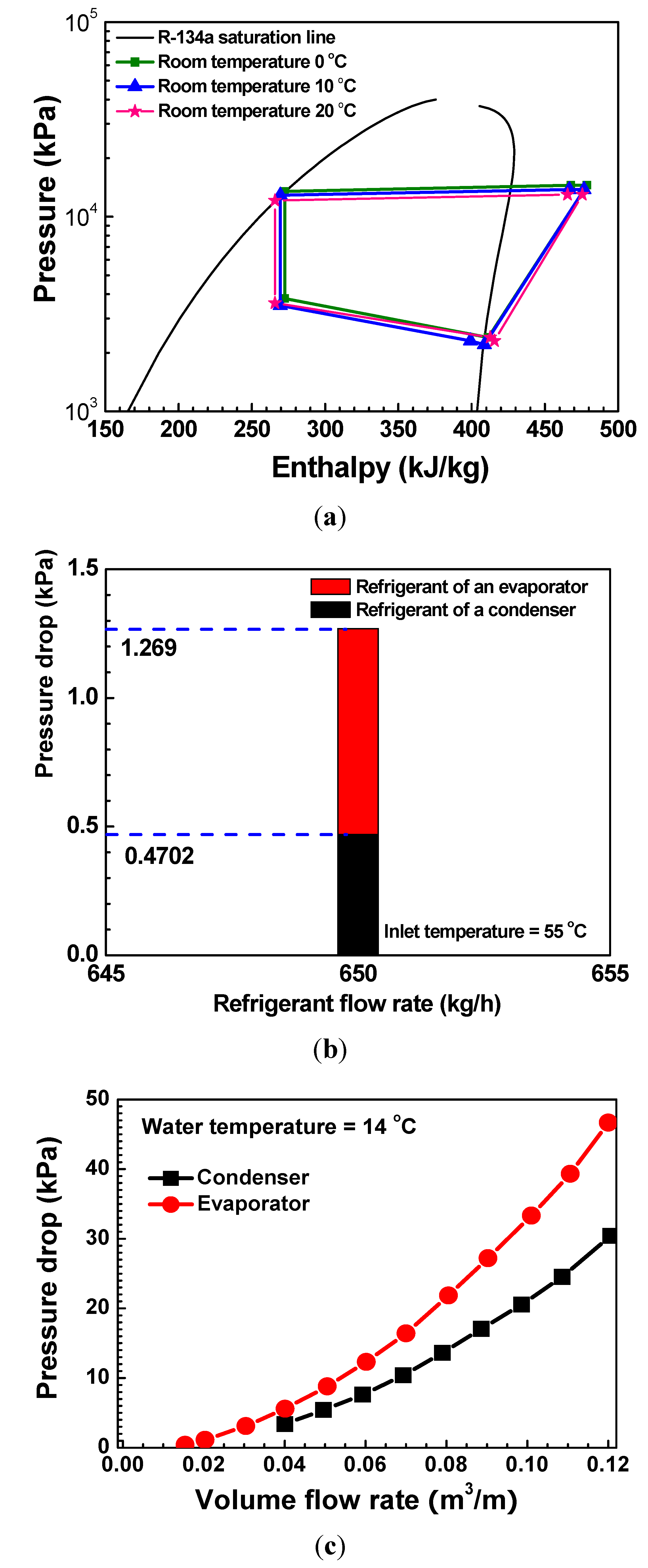
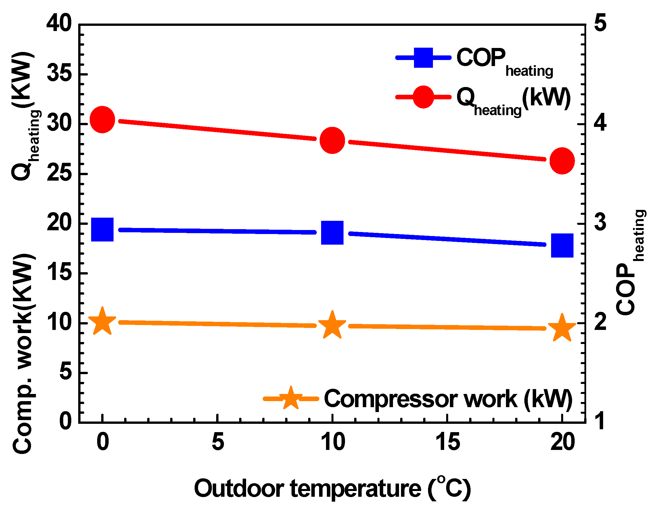
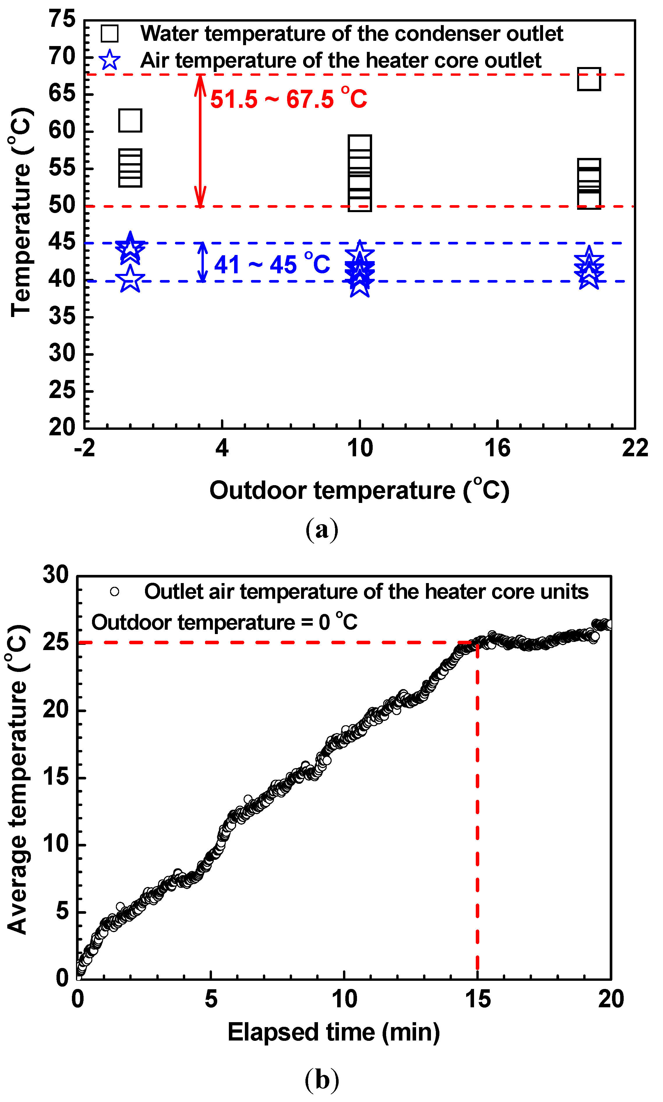
3.1. Steady State Performance

By using the refrigerant charge matching method for the heating system, as mentioned in Lee et al. [7], the refrigerant charge of the heat pump for heating was set to 8,500 g at an indoor temperature of 10.0 °C, water flow rate for the condenser of 0.020 m3/min, and water flow rate for the evaporator of 0.040 m3/min. In addition, the mass flow rate of the heat pump for heating was 540.0 kg/h at the compressor frequency of 60.0 Hz.
Figure 2(a) shows the pressure and enthalpy relation of the coolant source heat pump, using the wasted heat of electric devices for an electric bus designed in this study. The heat pump in the heating mode required relatively low compressor work, hence the high value of the heating heat transfer efficiency (heating COP) compared with other heating systems, such as the PTC heater only. This is the case as working across a small temperature gradient, between the heat source and heat sink, requires little input in order to transport heat. The expansion device in this system is the thermostatic expansion valve (TXV). The TXV automatically and effectively controlled the amount of pressure drop with a heat load, and it properly impacted the compressor work. As shown in Figure 2(a), the heating COP decreased with the rise of outdoor temperature, due to decrease in the required heating capacity. The rated refrigerant pressure drop at the evaporator side was 270% higher than that of the condenser side under equal test conditions, as shown in Figure 2(b). Figure 2(c) shows the water pressure drop at the evaporator and condenser sides. Both heat exchangers were tested with water flow rate under an inlet water temperature of 14 °C. The water pressure drop of the evaporator side was, on average, 55.4% higher than that of the condenser side at water flow rates ranging from 0.044 m3/min to 0.120 m3/min. Hence, as shown in Figure 2(a), the pressure drop of the evaporator was higher than that of the condenser.
Figure 2. (a) Pressure and enthalpy relation; (b) refrigerant pressure drop at evaporator and condenser sides; and (c) water pressure drop.
Energies 05 00658 g002
Figure 3 shows variations in the compressor work, heating capacity, and heating COP, with the outdoor temperature. This test was performed at 0.020 m3/min and 0.040 m3/min of water flow rate for condenser and evaporator sides, respectively, and 15.0 °C of inlet water temperature for the evaporator side. Generally, heating capacity and heating COP increase with the rise in outdoor temperature in a constant expansion device (Cho [8]). However, in this study, the pressure drop at the TXV is automatically controlled with outdoor temperature changes. The heating COP decreased by approximately 7.0% with the increase of outdoor temperature from 0 °C to 20.0 °C, because heating capacity decreased by 11.57%, although the compressor work decreased by 5.06%. The heating COP was 3.0 at an outdoor temperature of 0 °C.
Figure 3. Variations of the compressor work, heating capacity, and heating COP with the outdoor temperature.
Energies 05 00658 g003
Figure 4 shows variations in the compressor work, heating capacity, and heating COP, with water flow rate for the condenser side at the outdoor temperature of 10.0 °C. This test was performed under water flow rate, for the evaporator side, of 0.035 m3/min, an outdoor temperature of 10.0 °C, and 15.0 °C of inlet water temperature for the evaporator side. The heating COP increased by approximately 6.73% with the increase in water flow rate for the condenser side, from 0.015 m3/min to 0.025 m3/min, because heating capacity increased by 3.23% and the compressor work decreased by 3.15%. This happens because the performance of the heat pump varied with the operating conditions of the heat sink discharged from electric devices in this study. The heating COP was 3.17 at the water flow rate of 0.025 m3/min at the condenser side.
Figure 4. Variations of the compressor work, heating capacity, and heating COP with the water flow rate for condenser side.
Energies 05 00658 g004
Figure 5 shows variations in the compressor work, heating capacity, and heating COP, with the water flow rate for an evaporator side at the outdoor temperature of 10.0 °C. This test was performed under water flow rates of 0.020 m3/min for the condenser side, an outdoor temperature of 10.0 °C, and 15.0 °C of inlet water temperature for the evaporator side. The heating COP decreased by approximately 5.07% with the increase in water flow rate for the evaporator side, from 0.035 m3/min to 0.050 m3/min, because compressor work increased by 6.31%, although the heating capacity increased by 6.63%. The heating COP was 3.06 at the water flow rate of 0.035 m3/min for the evaporator side. The observed characteristics of the heating COP and heating capacity, with variation in operating conditions, suggest that the heat pump designed in this study is applicable to the cabin heater of an electric bus, which is limited by short driving range. In addition, the heating COP of 3.0 at an outdoor temperature of 0 °C means a greater increase in the driving range of the electric bus than is possible when PTC heaters with maximum efficiency of 1.0 are used for cabin heating. Heating capacity of over 25.0 kW may be sufficient for the heating of general buses as well as express buses.
Figure 6 shows variations in the drop as well as the heat transfer rate at the heater core, with working fluid changes. The heat transfer rate at the heater core, using water as working fluid, was on average 32.0% higher than that of the ethylene glycol-water mixture (50:50%) yet the pressure drop was, on average, 40.9% lower than that of the ethylene glycol-water mixture (50:50%). This occurs because the viscosity of the water is lower than that of the ethylene glycol-water mixture (50:50%) but the heat transfer of water was higher than that of the ethylene glycol-water mixture (50:50%). Therefore, as shown in Figure 6(b), the heat transfer rate will decrease when ethylene glycol-water mixture is used as the working fluid.
Figure 5. Variations of the compressor work, heating capacity, and heating COP with the water flow rate for evaporator side.
Energies 05 00658 g005
Figure 6. Variations of the pressure drop and heat transfer rate at the heater core with working fluid changes. (a) Pressure drop with volume flow rate; (b) Heat transfer rate with volume flow rate.
Energies 05 00658 g006aEnergies 05 00658 g006b

3.2. Transient Temperature Performances

Transient temperature variations at warm-up conditions for vehicles are a significant performance parameter of the heat pump system, as mentioned in Kim et al. [9]. The transient performance was evaluated at an outdoor temperature of 0 °C, and the warm up speed of the air temperature at the heater core outlet for the cabin heating was also considered. Superior warm-up performances in vehicles operated under cold weather conditions allow passengers to feel more comfortable. Generally, a comfortable temperature for passengers is approximately 25.0 °C, as mentioned in Kim et al. [10]. The electric-driven compressor used in the coolant source heat pump, using the wasted heat from electric devices for electric vehicles, is independent of the vehicle speed and can be actively controlled to meet the heating load in the cabin, at startup, under various cold weather conditions. Furthermore, it is one of the merits of the heat pump which uses the electric driven compressor rather than internal combustion engines. The coolant warm up time during the cold engine start, with an internal combustion engine, is strongly dependent on the coolant temperature using the wasted heat of the engine, as mentioned in Kim et al. [11].
Figure 7(a) shows the transient temperature variations of the outlet air of the heater core units as cabin heaters for compressor start-up. The average outlet air temperature of the heater core units was 25.0 °C after 15 min and increased to a maximum of 45.0 °C, as shown in Figure 7(b), which plots the water temperature of the condenser outlet and the air temperature of the heater core outlet, with variation in outdoor temperature. The water temperature of the condenser outlet and the air temperature of the heater core outlet are, on average, 55.4 °C and 41.9 °C, respectively, with variation in the outdoor temperature. However, the air temperature of the heater core outlet of the conventional coolant heating system using the wasted heat from the internal combustion engine is generally over the minimum 50.0 °C. Therefore, to improve the heating performance and quick warm-up response for passengers, a study on the hybrid coolant source heat pump at both above and below of 0 °C of the indoor temperature, using the additional PTC heater with the heater core, is necessary. In addition, this should be considered in the design stage of the coolant source heat pump, using the wasted heat of the electric devices for a cabin heating of an electric bus. The performance of the tested heat pump, through the steady state and transient conditions, shows that it can be used as a heating system for the cabin heating of an electric driven bus.
Figure 7. Transient temperature performances at warm up condition of the heater core units and variations of the water temperature of the condenser outlet and air temperature of the heater core outlet with the outdoor temperature. (a) Transient air temperatures; (b) Average outlet temperatures.
Energies 05 00658 g007

4. Summary and Conclusions

This paper explored the heating performances of the coolant source heat pump for an electric bus designed to make maximum use of the exhaust heat from its electric devices. The heating performance characteristics of the heat pump, using R-134a, were experimentally investigated by varying the outdoor temperature and water flow rates for the condenser and evaporator sides. The heating COP decreased with the rise of the outdoor temperature and water flow rate for the evaporator side, but heating COP increased with the rise of water flow rate on the condenser side. In addition, the heating COP was 3.0 at an outdoor temperature of 0 °C, and heating capacity was over 25.0 kW with variation of e outdoor temperatures. The average air temperature of the heater core outlet was 25.0 °C, after 15, minutes and increased up to a maximum of 45.0 °C. The water temperature of the condenser and the air temperature of the heater core unit outlet are, on average, 55.4 °C and 41.9 °C, respectively.

Acknowledgement

This work was supported by a grant from the Ministry of Knowledge Economy, Republic of Korea.

References

  1. Park, B.D.; Won, J.P.; Lee, W.S. Development of heat pump system for high efficiency engine vehicle. J. Korean Soc. Ind. Appl. 2007, 10, 21–26. [Google Scholar]
  2. Lawrence, P.S.; Mahmoud, G.; James, A.; Prasad, S.K. On-vehicle performance comparison of an R-152a and R-134a heat pump system. In Proceedings of SAE 2003 World Congress & Exhibition, Detroit, MI, USA, 3 March 2003. 2003-01-0733.
  3. Shin, S.K.; Lim, S.J.; Moon, J.H.; Cho, Y.; Koo, T.; Lee, S. R-124a heat pump application for the buses by using engine coolant as a heat source. In Proceedings of Commercial Vehicle Engineering Congress & Exhibition, Chicago, IL, USA, 7 October 2008. 2008-01-2697.
  4. ANSI/AMCA 210. In Laboratory Methods of Testing Fans for Rating; ANSI: Arlington, VA, USA, 1985.
  5. ASHRAE Standard 116. In Methods of Testing for Seasonal Efficiency of Unitary Air-Conditioners and Heat Pumps; ASHRAE: Atlanta, GA, USA, 1983.
  6. Moffat, R.J. Uncertainty analysis in the planning of an experiment. J. Fluids Eng. 1985, 107, 173–178. [Google Scholar] [CrossRef]
  7. Lee, M.Y.; Cho, C.W.; Lee, H.S.; Lee, D.Y.; Park, Y.C.; Won, J.P. Performance characteristics of a simultaneous hybrid heat pump using coolant and air sources for an electric bus. Int. J. Refrig. 2011. submitted. [Google Scholar]
  8. Cho, H.Y. Study on the Performance Improvement of a Transcritical CO2 Heat Pump. Ph.D. Thesis, Korea University, Seoul, Korea, 2005. [Google Scholar]
  9. Kim, S.C.; Kim, M.S.; Hwang, I.C.; Lim, T.W. Heating performance enhancement of a CO2 heat pump system recovering stack exhaust thermal energy in fuel cell vehicles. Int. J. Refrig. 2007, 30, 1215–1226. [Google Scholar] [CrossRef]
  10. Kim, S.C.; Park, J.C.; Kim, M.S. Performance characteristics of a supplementary stack-cooling system for fuel-cell vehicles using a carbon dioxide air-conditioning unit. Int. J. Automot. Technol. 2010, 11, 893–900. [Google Scholar] [CrossRef]
  11. Kim, K.B.; Choi, K.W.; Lee, K.H.; Lee, K.S. Active coolant control strategies in automotive engines. Int. J. Automot. Technol. 2010, 11, 767–772. [Google Scholar] [CrossRef]

