Article

Intelligent Control of Battery Energy Storage for Multi-Agent Based Microgrid Energy Management

1
School of Electrical Engineering, Kookmin University, 861-1, Jeongneung-dong, Seongbuk-gu, Seoul 136-702, Korea
2
Korea Electric Power Research Institute, 105 Munji-Ro, Yuseong-Gu, Daejeon 305-760, Korea
*
Author to whom correspondence should be addressed.
Energies 2013, 6(10), 4956-4979; https://doi.org/10.3390/en6104956
Submission received: 12 August 2013 / Revised: 16 September 2013 / Accepted: 16 September 2013 / Published: 25 September 2013

Abstract

:
Microgrids can be considered as controllable units from the utility point of view because the entities of microgrids such as distributed energy resources and controllable loads can effectively control the amount of power consumption or generation. Therefore, microgrids can make various contracts with utility companies such as demand response program or ancillary services. Another advantage of microgrids is to integrate renewable energy resources to low-voltage distribution networks. Battery energy storage systems (BESSs) can effectively compensate the intermittent output of renewable energy resources. This paper presents intelligent control schemes for BESSs and autonomous energy management schemes of microgrids based on the concept of multi-agent systems. The proposed control scheme consists of two layers of decision-making procedures. In the bottom layer, intelligent agents decide the optimal operation strategies of individual microgrid entities such as BESSs, backup generators and loads. In the upper layer, the central microgrid coordinator (MGCC) coordinates multiple agents so that the overall microgrid can match the load reduction requested by the grid operator. The proposed control scheme is applied to Korea Power Exchange’s Intelligent Demand Response Program.

1. Introduction

Microgrids have recently emerged as a new paradigm for future power systems because they can host multiple renewable energy resources in local distribution systems and also can supply reliable electric power to customers. State-of-the-art power electronic interfaces of distributed resources in microgrids can enhance the control capability of the microgrids against disturbances and uncertainties of the grids. Therefore, microgrids can be defined as autonomous power networks that can act as a controllable unit in power systems [1,2].
The technical and economic benefits of microgrids can provide leverage for the expansion of microgrids in power systems. For example, microgrids can supply ancillary services to power grids such as voltage support, harmonic compensation, and power reserve margin supplement [1,2,3,4]. In this sense, this paper focuses on the demand response (DR) program where microgrids can provide economic profits from the energy market. Normally in DR programs, the grid operators require fast load reduction within a certain amount of time. However, instant power interruption makes customers suffer monetary losses and lost opportunity costs. If the microgrid operators could manage their distributed energy resources in a smarter way, load reduction and financial losses can be minimized. Therefore, this paper presents intelligent DR schemes of microgrids using intelligent multiple agents. In this paper, the proposed method is applied to the Intelligent DR program of the Korea Power Exchange (KPX) that is a type of emergency demand response (EDR) program [5,6]. This EDR program of KPX is elaborated in Section 2. The proposed method utilizes the distributed intelligence to optimize the overall economic benefits of the microgrids and to adjust possible conflicts between the microgrid entities.
Recently, it has been shown that microgrids can improve their performance by utilizing battery energy storage systems (BESSs). First of all, when microgrids host renewable energy resources in low voltage distribution systems, the intermittent output of renewable energy resources can cause disturbances in power quality and uncertainties in the secure operation of microgrids. BESSs can act as energy buffers for renewable energy resources so that BESSs can compensate for short-term variation of power output of renewable energy resources. In addition, BESSs can shave daily peak loads by charging the surplus energy during off-peak loading period and discharging during emergency or peak-loading conditions. This paper focuses on the intelligent control of BESS for microgrid energy management. There have been researches for BESS control schemes [7,8]. Reference [7] provides a rule-based control scheme for a BESS to compensate for the variations of solar PVs and wind turbines. The developed control scheme consists of simple rules to consider the limitations on the state-of-charge (SOC) of the battery and the size of charging/discharging currents. Reference [8] proposes fuzzy-logic-based BESS control scheme for a DC microgrid that consists of a solar PV and fuel cells for generation and two BESSs and a super capacitor for energy storage. The BESSs control the charging and discharging actions to keep the generation power of the overall microgrid uniformly. This paper proposes an intelligent control scheme for a BESS based on the concept of multi-agent system. The proposed BESS agent is controlled as a state machine according to the changes in microgrid environments. The details of the control states will be discussed in Section 3. The validity of the proposed method is examined via diversified case studies, which are provided in Section 4.

2. Microgrid Model

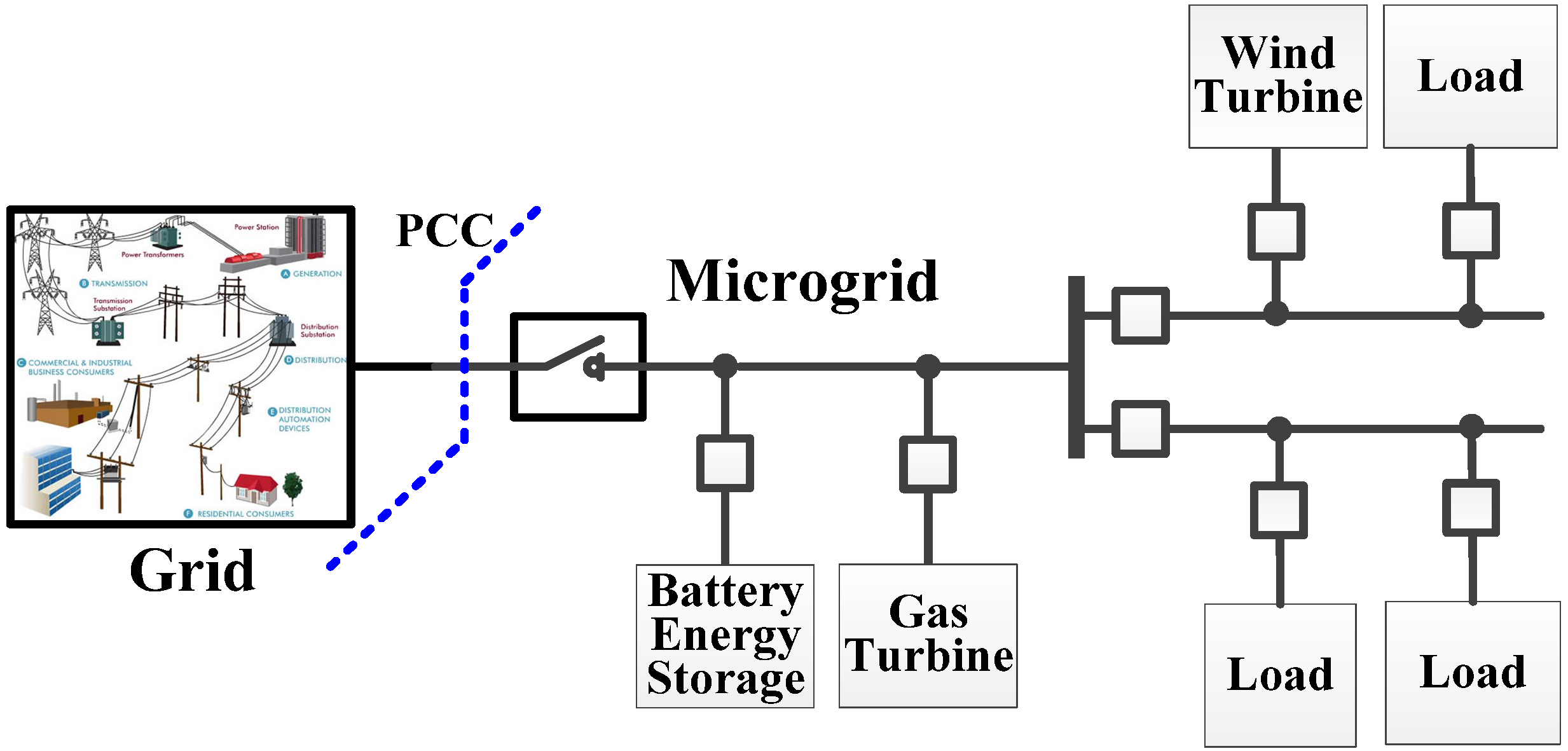
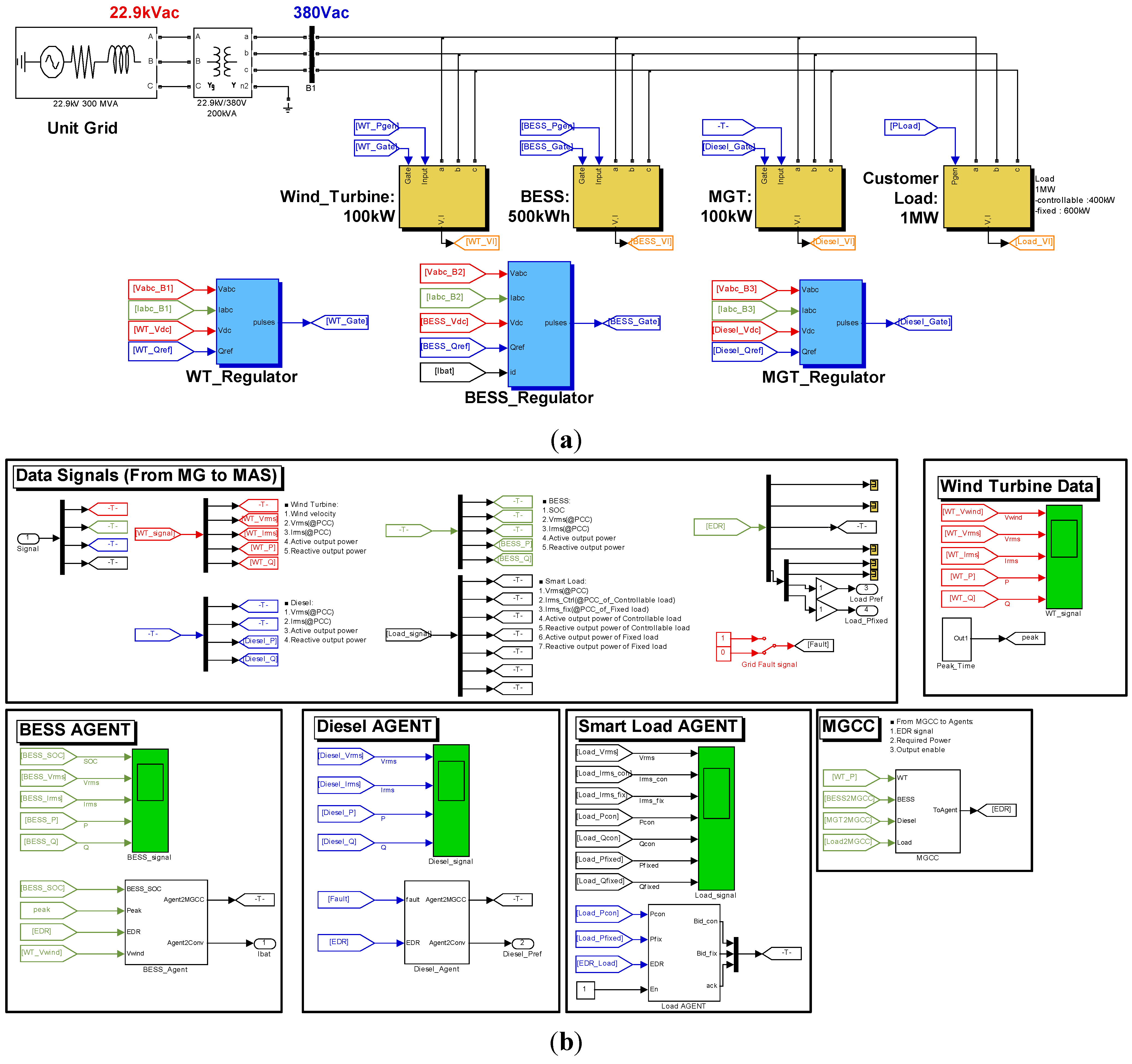
2.1. Microgrid Configuration

Microgrids can effectively control various multiple entities such as diverse distributed energy resources and electric loads with a variety of load characteristics. This paper considers a microgrid model that contains a battery energy storage system (BESS), a wind power system, a micro gas turbine (MGT) generator, and controllable and critical loads to apply the proposed microgrid control scheme without losing generosity. Figure 1 illustrates the single-line diagram of the microgrid used in this paper. The ratings of the microgrid entities are listed in Table 1.
Figure 1. Configuration of overall microgrid control network.
Energies 06 04956 g001
Table 1. Ratings of microgrid entities.
EntityRatingConfiguration
Wind Power System100 kWPMSG with a full-scale three-level converter
BESS500 kWhLi-ion battery model with non-isolated bi-directional boost converter and three-level converter
Micro Gas Turbine100 kWBack-up generation for emergency conditions
Load1 MW (peak)Critical load: 600 kW (peak), Controllable load: 400 kW (peak)

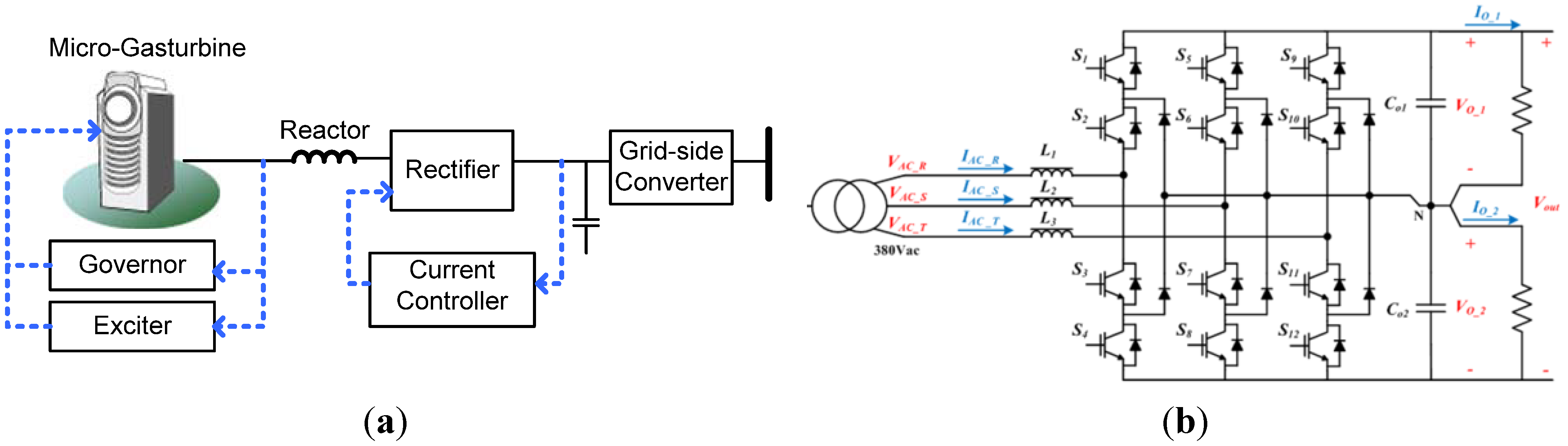
2.2. Microgrid Gas Turbine

A MGT is modeled by equivalent synchronous generator and a rectifier and three-level grid converter as illustrated in Figure 2a. Because the frequency of the MGT is higher than that of the grid, e.g., 300 Hz, the rectifier converts it to DC power and the grid converter integrates to the grid.
In the developed microgrid model, three-level neutral-clamped inverters, which can reduce the rating of semiconductor devices and lower harmonic distortion to the grid, are chosen for the grid-side converters for wind power, BESS and MGT. The configuration of the grid-side converter is shown in Figure 2b.
Figure 2. Configuration of MGT and grid-integrate converter: (a) Micro-Gas Turbine; (b) Three-level NPC-type power converter.
Energies 06 04956 g002

2.3. Battery Energy Storage Model

BESSs can compensate instant power variation of the wind power system so that power quality can be maintained and the grid can avoid low frequency oscillation. They can also shave the peak loads. Figure 3 illustrates the equivalent model of BESS that contains a Li-ion battery model and a grid converter. The Li-ion battery stack is directly connected to the grid-side converter. The BESS controller consists of a converter controller and a battery agent. The converter controller controls the current of a power converter based on the synchronous reference frame. It is mostly the same as controller of grid-connected inverter but a current reference is made by the battery agent. The fuzzy-based artificial intelligence algorithms are applied to the battery agent for the effective control of battery operation. The charging and discharging modes are determined by the level of the SOC of the battery because the SOC should be maintained over 30% [7]. The charging and discharging current rates are decided by a wind speed and the customer base line (CBL).
Figure 3. Configuration of BESS and control block diagram.
Energies 06 04956 g003

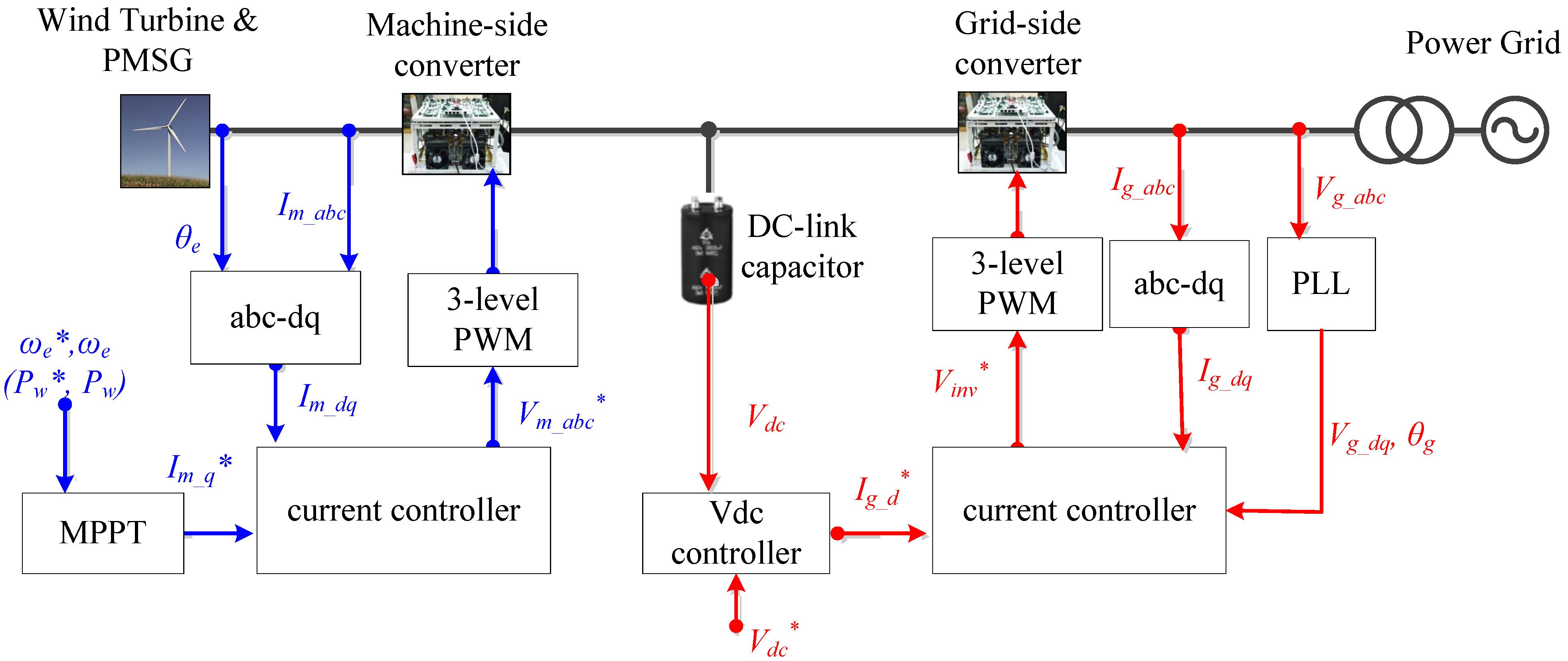
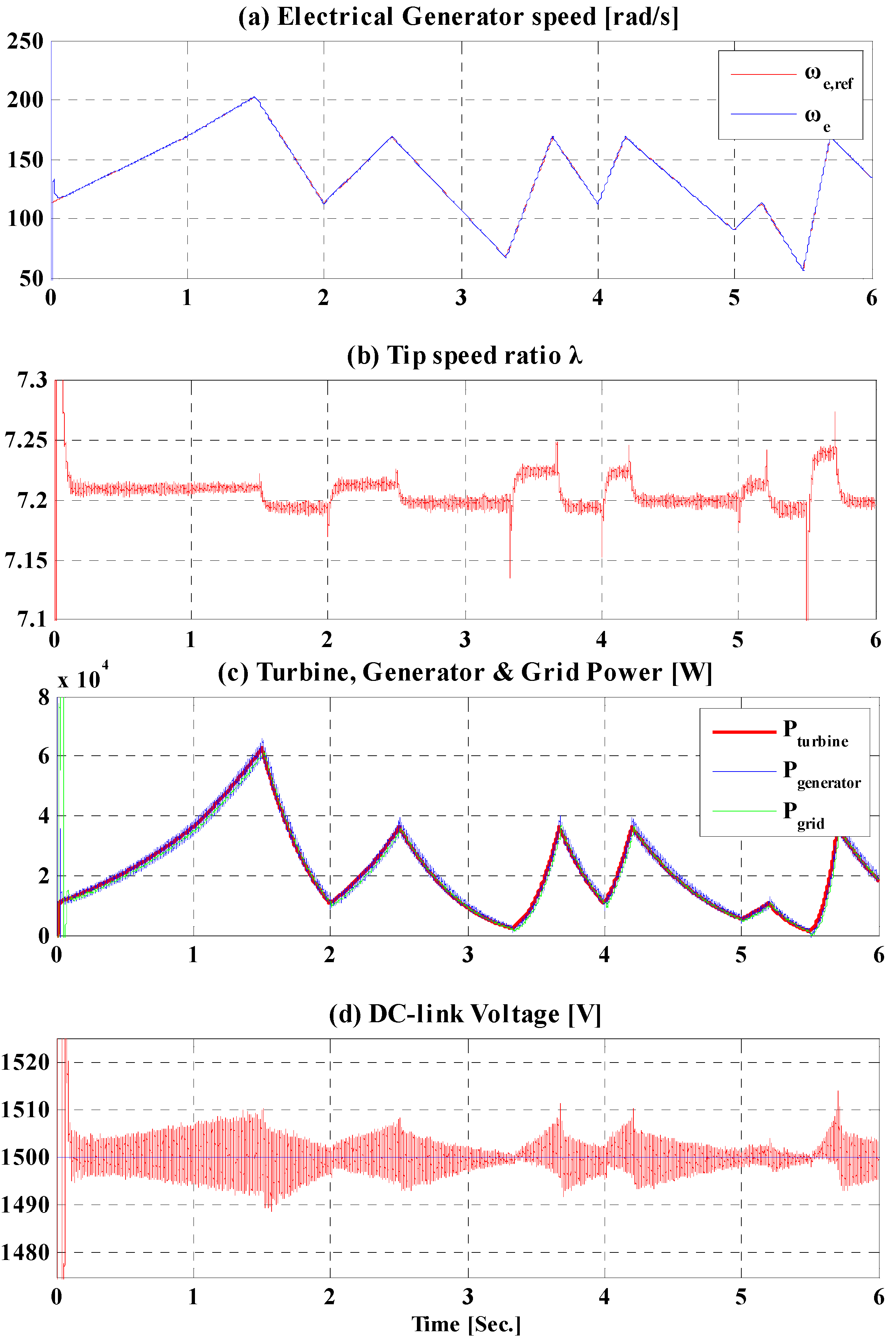
2.4. Wind Turbine Model

The wind power system is modeled with a full-scale back-to-back converter with a permanent magnet synchronous generator (PMSG) [9]. The power generated by the wind turbine (WT) is rectified to DC power and then converted to ac by a three-level voltage source inverter. Figure 4 illustrates the configuration of the full-scale wind power system used in this paper. In general, wind power systems should track the maximum power points during normal operations satisfying the grid code especially during fault conditions.
Figure 4. Configuration of wind power system and control block diagram.
Energies 06 04956 g004
The rotational speed of the PMSG is controlled by the machine-side converter (MSC) to extract the maximum power from the WT while the grid-side converter (GSC) controls the DC-link voltage and the reactive power output. Figure 5 shows the simulation results of the wind power system with variable wind speed, which is given as Figure 5a.
Generally, the power from the wind turbine that is proportional to the cube of the wind speed and the tip speed ratio can be obtained as:
P w = 1 2 ρ π r 2 v w 3 C p ( λ , β )
λ = ω t r v w
where ρ is the air density; r is the radius of the turbine blade; vw is the velocity of wind; Cp is the WT power coefficient; λ is the tip speed ratio; ωt is the rotational speed of the WT rotor; and β is the pitch angle, respectively [9]. By using Equations (1) and (2), the maximum power from the WT can be derived as:
P w , m a x = K o p t ω t , o p t 3
where Kopt and ωt,opt can obtained as:
K o p t = 1 2 ρ π r 2 C p , max ( r λ o p t ) 3
ω t , o p t = λ o p t v w r
Figure 5. Simulation results of the wind turbine system: (a) electrical speed of synchronous generator; (b) tip speed ratio of the wind turbine; (c) output power of the turbine, generator and grid-side converter; and (d) dc-link voltage.
Energies 06 04956 g005
The maximum value of the power coefficient Cp,max is known as 0.4412 at the optimum tip speed ratio λopt, which is also known as 7.206. In the developed model, the radius of WT is set to 11 m and the rated wind speed is set to 10 m/s. Then, the maximum turbine torque can be derived as:
T t u r b i n e _ max = P w , max ω t , o p t = K o p t ω t , o p t 2
It is noted that the turbine torque is proportional to the generation power of the turbine. The optimum mechanical rotational speed of the generator ωm,opt and the optimum electrical rotational speed of the generator ωe,opt, which is the reference signal for the MSC, can be calculated as:
ω m , o p t = N g r ω t , o p t
ω e , o p t = N p p ω m , o p t
where the Ngr and Npp are constants representing the gear ratio and the number of pole pair of the PMSG, respectively.
As seen in Figure 5, the MSC controls the generator speed whereas the generated power from the wind resource flows into the grid via the GSC. The optimal electrical rotational speed of the generator ωe,opt, which is derived from Equation (8), is applied as the reference of MPPT controller as shown in Figure 4. As represented in Figure 5a, the measured rotational speed of generator is controlled to follow ωe,opt for the MPPT operation. As a result, the measured tip speed ratio, which is shown in Figure 5b, is maintained around 7.2, even if the wind speed changes. The generated power of the WT is proportional to the cube of the electrical rotational speed according to Equation (3) and the simulation results are shown in Figure 5c. The GSC controls the DC-link voltage and reactive power. In the developed WT model, the DC-link voltage is controlled within 3% deviation as shown in Figure 5d and the reactive power of GSC is controlled to be zero.

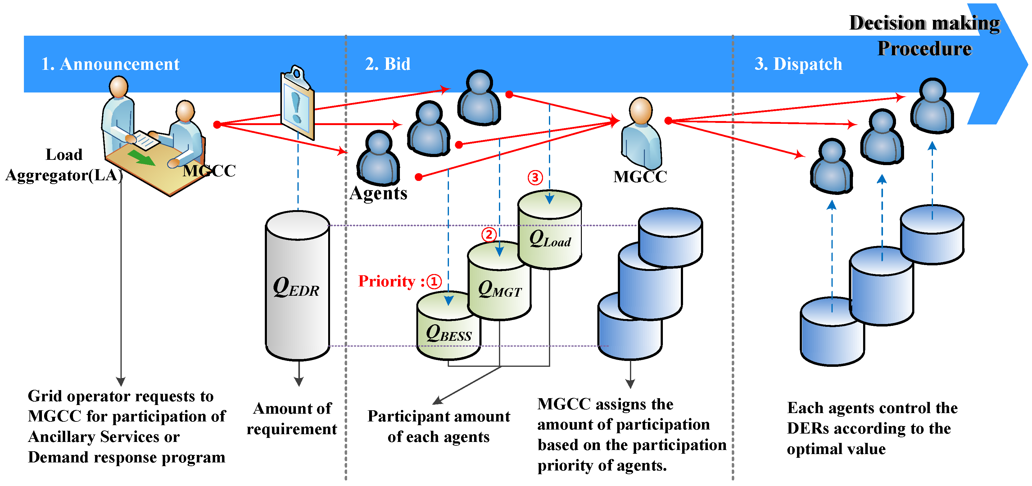
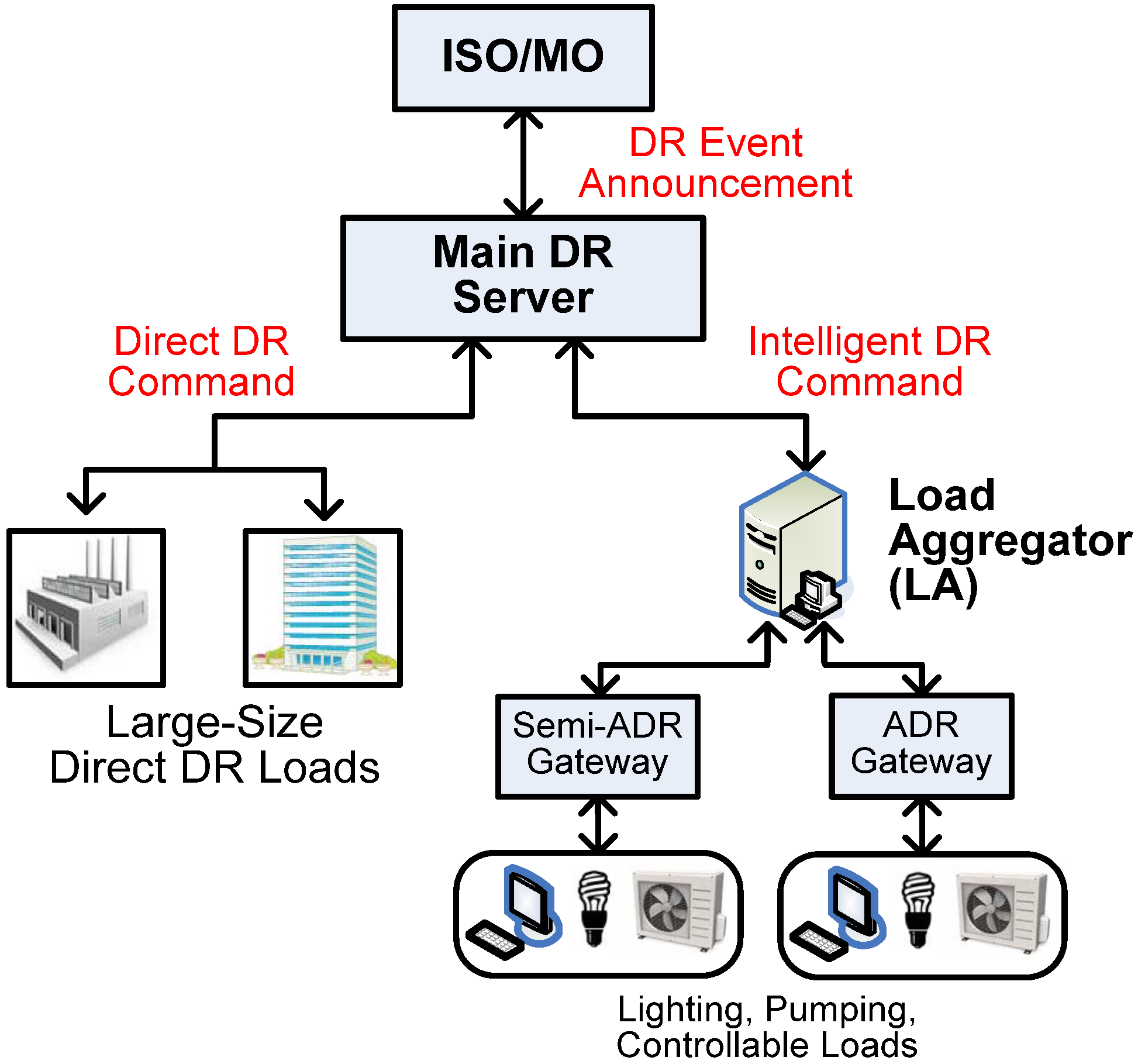
3. Multi-Agent Based Energy Management for Demand Response Program

3.1. Emergency Demand Response Program

To securely operate electric power systems, the independent system operator (ISO) must maintain a certain amount of power reserves all the time. However, due to the fast increase in electricity usage, it becomes more difficult to meet the reserve margin. Therefore, demand response (DR) programs can be an effective solution for power system security. DR programs can be defined as the changes in electric power consumption of end-use loads during the critical period, normally the peak loading conditions [10,11,12]. DR programs are divided into two categories: incentive-based programs and price-based programs. The emergency demand response (EDR) program is a representative incentive-based DR program in which participants are rewarded for their load reduction in response to the requests of the ISO. Price-based DR programs such as Time-of-Use (TOU) and Critical-Peak-Pricing (CPP) programs are based on dynamic pricing rates in which electricity prices change during a day. Generally, the prices in price-based DR programs are high during peak periods and low during off-peak periods.
Figure 6 illustrates the concept of DR programs developed by the Korea Power Exchange (KPX) that consists of two DR markets: the Direct DR market for large-size loads and the Intelligent DR market for medium small-size loads. This paper focuses on the Intelligent DR Program (IDRP), which is a sort of an EDR program. Under the IDRP, the customers, who can reduce overall power consumption between 100 kW and 3000 kW, can make contracts with KPX directly or through load aggregators (LAs). Small-size customers, whose load reduction capability is less than 100 kW, must contract with LAs to participate in the DR program. ISO pays the incentives in two ways: the unit capacity price for the amount of the contract DR power of the load, which is about 60 USD/kW once a year, and the performance incentives for the delivery of the contract about 0.5 USD/kWh for every DR event that is five times higher than the average electricity price. If any customers cannot fulfill the contract, they must pay certain amount of penalty.
Figure 6. Conceptual diagram for KPX’s DRP.
Energies 06 04956 g006
KPX limits the maximum number and duration of DR events as 30 times and 60 hours a year and two to three hours a day. The customers must install smart meters to send the power measurement data to the LA servers every 15 min. The LAs calculate the actual load reduction as the difference between the measured load consumption and the Customer Base Line (CBL). The CBL is calculated every day based on the past 10-day power consumption data by using weighted averaging windows [5]. As shown in Figure 6, the customers can be divided into two groups such as automatic DR (ADR) loads and semi-ADR loads. ADR loads must achieve load reduction within 10 min while semi-ADR loads reduce the power consumption within 30 min.
The purpose of this paper is to apply microgrids to the above-mentioned IDRP of KPX, especially through ADR gateways. Compared to the typical loads, microgrids have more strengths as participants in the DR program because they have not only controllable loads but also energy resources. Therefore, microgrids have more flexibility to control the overall power consumption. For example, when the energy resources produce electric power, the loads in microgrids do not need to be cut out. In addition, when any DR participants cannot fulfill their DR contracts for some reasons, microgrids in the neighborhood can help them not to break the contract by producing more power to the grids. The design considerations of microgrid control schemes in this paper are the following:
Prompt decision-making process
Open and flexible control platform for diverse entities
Intelligent algorithms for optimal operation of each entity
Reliable DR operation with multiple back-up plans against uncertainties
To participate in EDR programs, load agents should be able to quickly reduce a certain amount of loads. To this end, the load agents must divide the loads into multiple classes such as critical and controllable loads before an EDR request. When MGCC requests load reduction, the load agent can cut the controllable loads instantly.

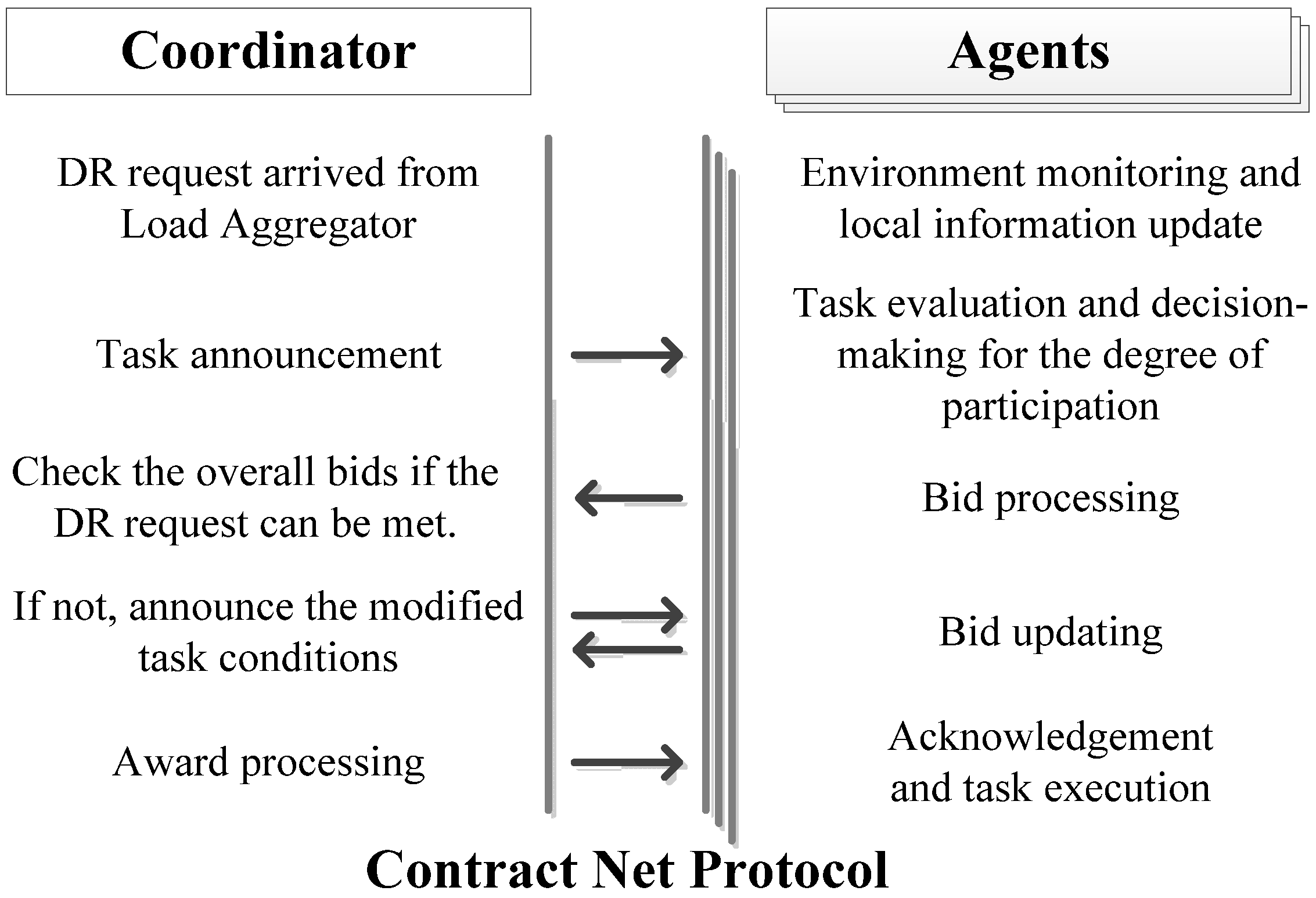
3.2. Multi-Agent Based Microgrid Energy Management
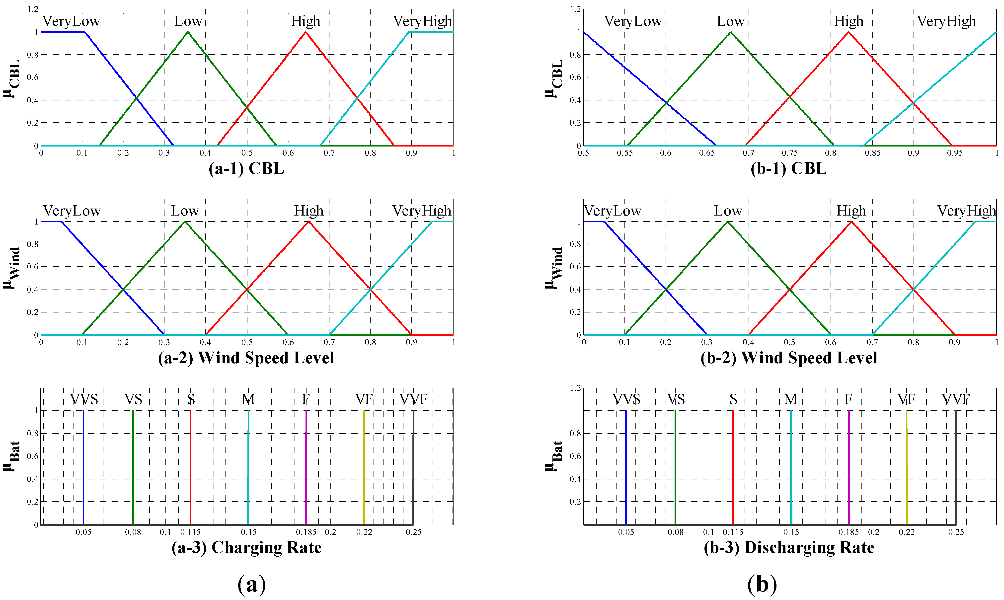
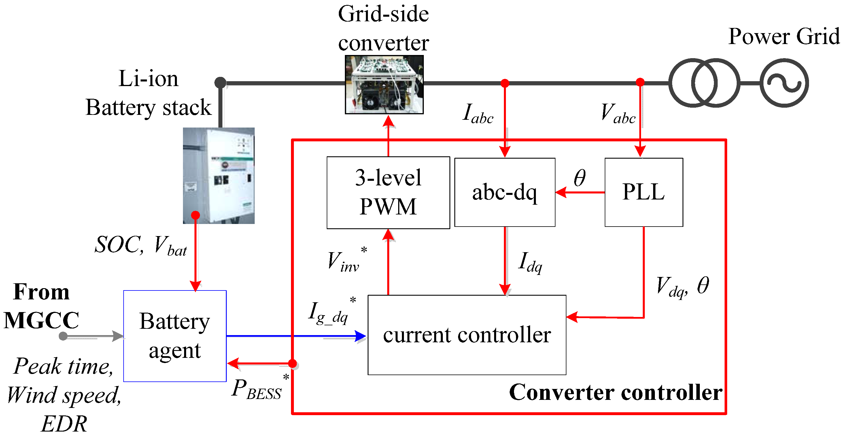
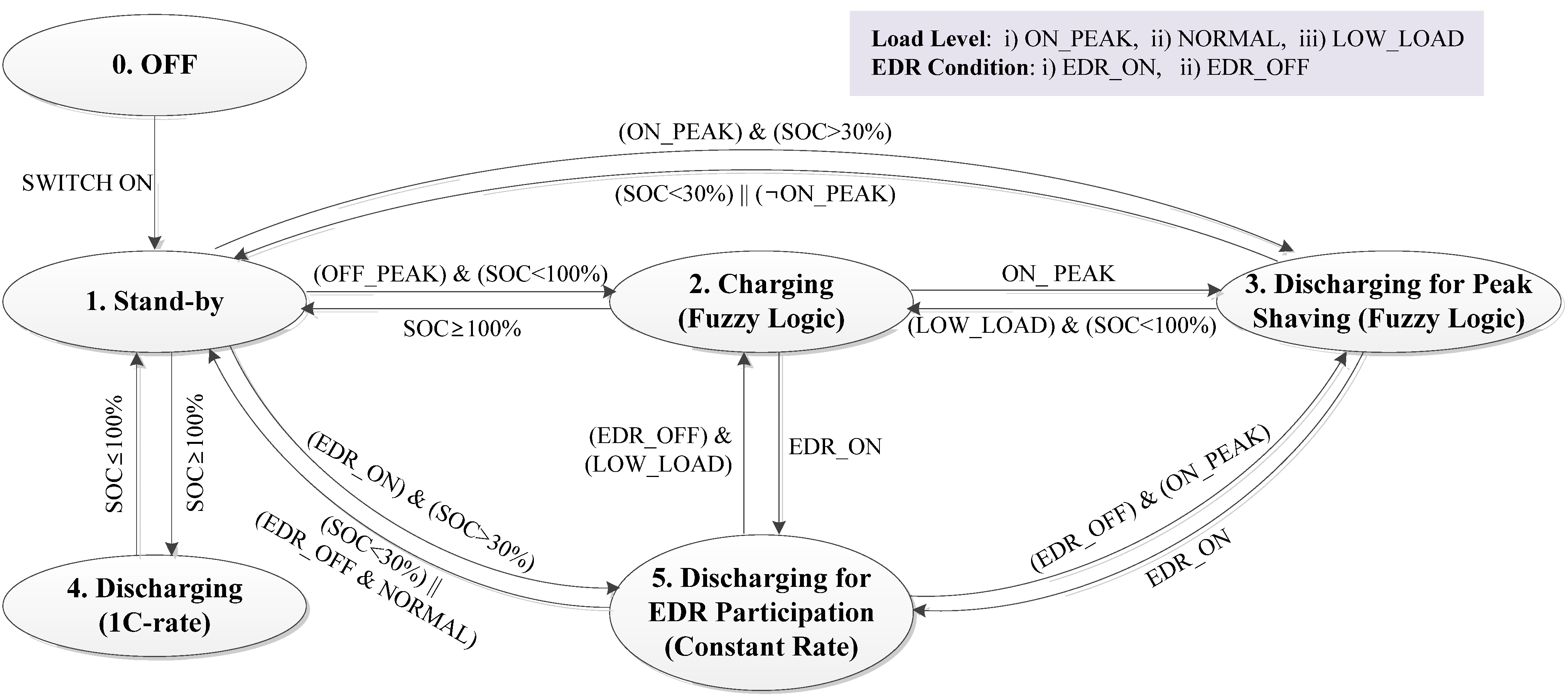
Centralized microgrid energy management systems have advantages when they manipulate the overall power generation or consumption of the whole microgrid but it is difficult to consider delicate interest of individual entities such as DERs and local loads and the communication. In addition, the computational burden in the central controller is intensive in centralized control systems. Compared to the conventional centralized control, multi-agent systems (MASs) have strengths to distribute computational burden to local agents and can consider the characteristics of individual entities by using intelligent algorithms [13]. The agents can obtain information by monitoring local systems and spontaneously communicating with other agents. The agents can make a decision on behalf of microgrid entities with artificial intelligence through negotiating and cooperating with other agents.
There have been many researches into the MAS-based microgrid control systems [14,15,16,17]. Reference [14] applies a MAS-based control concept on a DC microgrid to control the DC bus voltages and match the power demand. To communicate with other agents, the master agent that must control the bus voltage is determined by transferring the token between agents. Reference [15] explains the fundamental modules of agents such as data collection, communication, decision-making, action implementation, and knowledge management. References [15] and [16] present MAS-based economic power dispatch schemes under power pool or power market conditions. Both references apply the concept of the Contract Net Protocol (CNP) for the decision-making procedure. In our previous research, we also applied microgrid energy management schemes using MAS with CNP and also implemented a hardware-in-the-loop simulation system for experimental verification [17,18]. In this paper, we present improved intelligent control schemes for BESS agents using state machine concept and fuzzy-logic charging/discharging algorithms in order to participate in the IDRP of KPX. In addition, the decision-making procedure is also updated for more economical approach in DR power dispatch. Figure 7 illustrates the concept of the proposed control scheme.
In the proposed microgrid control system, sufficient intelligence of individual agents is a significant factor for the overall performance of the system. In addition, well-coordination of multiple agents is significant as well. In the developed system, the Microgrid Central Coordinator (MGCC) needs to coordinate multiple intelligent agents for the global objectives. When a special control request is delivered from the LA such as command for emergency demand response, the MGCC informs agents of the control objectives for the whole microgrid. After receiving the individual bids of the agents, the MGCC need to decide how to dispatch the control command to the agents. In this procedure, both communication and coordination are the most important factors to reach an overall coordination. The overall decision-making procedure follows the Contract Net Protocol (CNP).
The CNP provides a formal procedure in the coordination procedure in MAS-based management systems. The contract between the MGCC and the agents can be reached by the process of decision-making and interaction based on two-way communication. Figure 8 illustrates the concept of the CNP based decision-making procedure. The overall procedure starts when the main grid requests for certain actions such as demand response.
Figure 7. Configuration of multi-agent based microgrid energy management.
Energies 06 04956 g007
Figure 8. Communication between MGCC and agents using Contract Net Protocol.
Energies 06 04956 g008
In the CNP procedure, two layers of decision-making processes are needed: one in the MGCC and the other is in the agents. Agents should make a decision such as the degree of participation in the task requested by the MGCC. To approach the optimal solution, the agents evaluate the detailed information of the task and check local data such as incentives, operation cost, current states, loading conditions, and so on. The agents use artificial intelligent algorithms such as fuzzy-based expert systems to attain maximum benefits from the task. Then, the agents bid the amount of “EDR participation power” in kWh with the corresponding “incentive price” ($/kWh) for load reduction or extra-generation.
The MGCC decides the overall operation scheme for a microgrid after receiving the bids from the agents. When the total amount of EDR participation power proposed by the agents is sufficient, the MGCC choose the agents who submitted the cheapest bids. If the bids from the agents are not enough to meet the request from the grid, the MGCC commands mandatory generation and load shedding to the agents.

3.3. Battery Agent

In this paper, fuzzy-based artificial intelligence algorithms are applied to the BESS agent. The goals of the BESS agent are as follows:
To keep the battery SOC (State of charge) between 30 % and 100%.
To support the power generation during peak loading period or EDR event.
The main operating algorithms of the BESS agent are programmed based on a state machine concept. Figure 9 shows the state machine diagram of the developed BESS agent. The states are defined as follows:
State “0”: The BESS turns off.
State “1”: The BESS turns the power on and stands by.
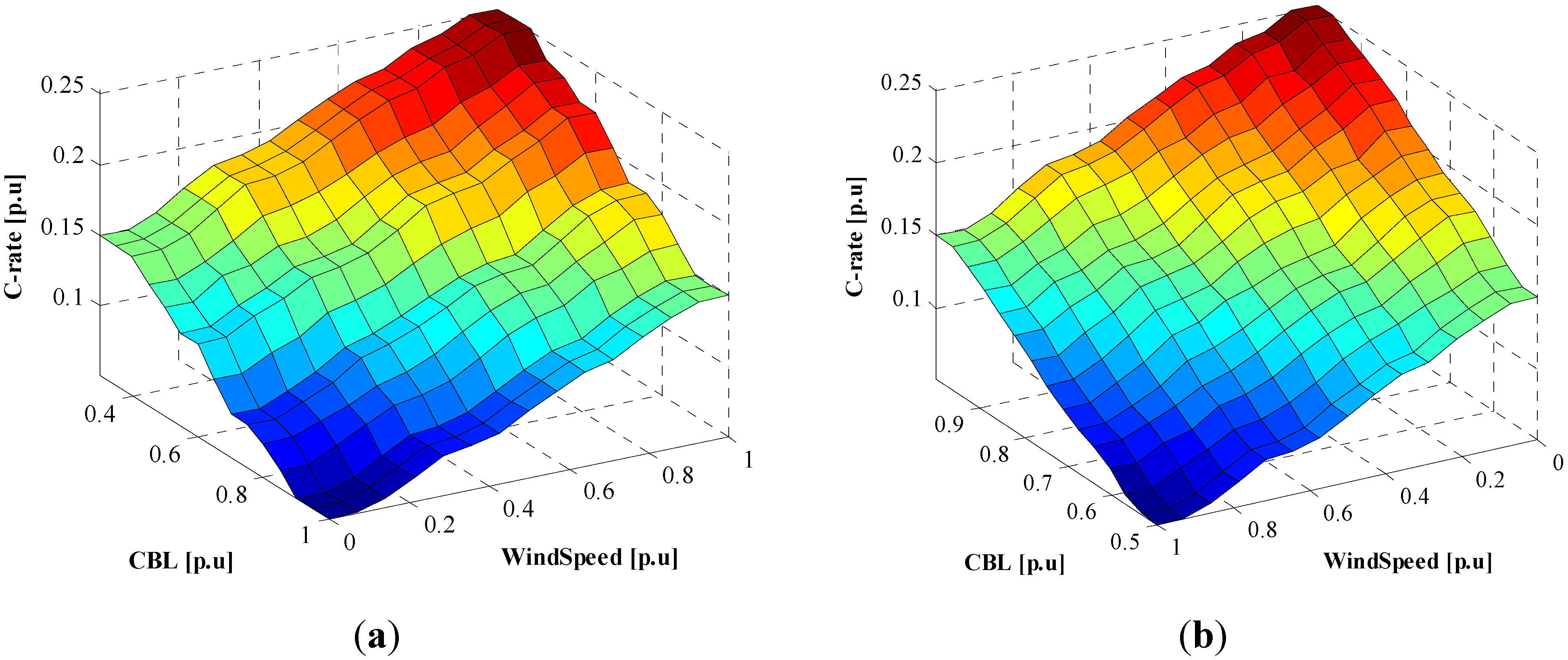
State “2”: The BESS charges the battery according to a fuzzy logic.
State “3”: The BESS discharges the battery according to a fuzzy logic during the peak loading condition.
State “4”: When the battery is overcharged (>100%), the BESS discharges the battery at a constant rate.
State “5”: In the EDR event, the battery is discharged at a constant rate.
The state of the BESS agent changes according to the load level, EDR signal, and the SOC level of the battery. The load level can be classified into three levels such as peak load (ON_PEAK), normal load (NORMAL), and low load (LOW_LOAD) whereas the EDR condition consists of on (EDR_ON) and off (EDR_OFF). When the BESS agent check the SOC level, hysteresis transition by including a small dead-band between states must be considered in the boundary conditions to avoid frequent state transition. The details of the state transition are graphically explained in Figure 9.
Figure 9. State transition diagram of battery agent.
Energies 06 04956 g009
Generally, the electricity rates are higher during peak loading period or EDR events. Thus, in order to pursue maximum profits for the BESS operator, the BESS needs to be charged during low-load period and discharged during peak load periods. The BESS charging algorithms during the low-load period in state “2” can be effectively implemented by fuzzy logic. The developed fuzzy algorithm for BESS charging consists of 16 fuzzy-logic rules considering two inputs: the CBL to check the load level and the wind speed to use charging energy from wind turbines as presented in Table 2. When the load level is low and there is abundant wind power, the charging rate of the BESS becomes higher. The detailed fuzzy membership functions and the defuzzifying function are illustrated in Figure 10a. The inputs consist of four fuzzy membership functions defined as: very low (VL), low (L), high (H), and very high (VH). For the output, seven fuzzy membership functions are defined to determine the charging current rate: very-very slow (VVS), very slow (VS), slow (S), medium (M), fast (F), very fast (VF), and very-very fast (VVF). The battery charging rate is determined by Sugeno-type fuzzy inference system as shown in Figure 10 (a-3). Considering the lifetime of battery, the charging or discharging current rate of fuzzy logic sets to 0.1–0.25 C-rate. Figure 11a displays the three-dimensional fuzzy map for battery charging rate.
Table 2. Fuzzy rule of battery charging for battery agent in state “2”.
CBLWind SpeedVLLHVH
VLMFVFVVF
LSMFVF
HVSSMF
VHVVSVSSM
Notes: VL: Very Low, L: Low, M: Medium, H: High, VH: Very High, VVS: Very Very Slow, VS: Very Slow, S: Slow, M: Medium, F: Fast, VF: Very Fast, VVF: Very Very Fast.
Figure 10. Membership functions: (a) Fuzzy membership function for BESS charging in State “2”; (b) Fuzzy membership function for BESS discharging in State “3”.
Energies 06 04956 g010
The discharging operation is defined by three states, “3”, “4”, and “5”, to consider peak load shaving, EDR participation, and battery SOC maintenance. In state “3”, the BESS discharges to support the power reserve of the main grid during the peak loading condition. In this state, the BESS discharging action is defined as the fuzzy logic explained in Table 3. The BESS discharging rule also consists of two inputs such as the CBL and the wind speed and one output of the battery discharging rate. The detailed fuzzy membership function is illustrated in Figure 10b using Sugeno-type fuzzy inference system. Figure 11b shows the three-dimensional fuzzy map for battery discharging in state “3”. State “4” defines the BESS discharging action to limit the battery SOC not to exceed 100%. Because the battery overcharging shortens the batter life span, the BESS needs to discharge rapidly. In state “4”, the BESS discharges by constantly controlling the discharging current at the speed of 1 C-rate until the SOC is equal to or less than 100%. To avoid frequent state transition when the SOC is around 100%, a certain amount of dead-band must be applied to the state transition.
Table 3. Fuzzy rule of battery discharging for battery agent in state “3”.
CBLWind speedVLLHVH
VLMSVSVVS
LFMSVS
HVFFMS
VHVVFVFFM
Notes: VL: Very Low, L: Low, M: Medium, H: High, VH: Very High, VVS: Very Very Slow, VS: Very Slow, S: Slow, M: Medium, F: Fast, VF: Very Fast, VVF: Very Very Fast.
Figure 11. Three-dimensional surface map of fuzzy inference system for battery agent: (a) Battery charging rule in state “2”; (b) Batter discharging rule in state “3”.
Energies 06 04956 g011
When the EDR event occurs, the BESS also need to discharge power in constant current mode. The amount of discharging power is determined by the decision-making of the MGCC as above-mentioned CNP algorithm. The available power that the BESS agent can make a bid to the MGCC can be determined as:
P B E S S E D R = P B E S S R a t e d ( S O C % 30 % 100 % ) 1 h o u r P B E S S I n i t i a
where P B E S S E D R is the amount of power that the BESS agent can bid for the EDR participation, P B E S S R a t e d is the rated power of the BESS, S O C % is the BESS SOC in percentage, and h o u r means the total duration of the EDR event, P B E S S I n i t i a is the initial discharging power prior to the EDR event, respectively. The bidding incentive price of the BESS will be the electricity rate during low-load period, which is normally much cheaper than peak-load period. Therefore, even though the BESS cannot generate power by itself, the BESS can act as a cheapest power generation solution during the EDR event.

3.4. MGT (Micro Gas Turbine) Agent

In our microgrid design, the MGT is designed as a back-up generator that operates during emergency conditions such as loss-of-mains when the microgrid loses the connection to the main grid. In addition, the MGT can also compensate the power deficiency due to lack of energy resources in the microgrid. For example, if the SOC of the BESS is low and the wind speed is not enough, it is difficult to satisfy the EDR request by the ISO. In this case, the MGT agent determines the EDR participation by comparing the generation cost and the EDR incentive. Normally, the EDR incentive is higher than the fuel cost of the MGT. Therefore, the MGT can be a back-up power source for EDR participation that has a lower rank than BESS discharging and load reduction of controllable loads.

3.5. Load Agent

The customer loads are divided into two classes: controllable loads and critical loads. The controllable loads can be cut off from the grid during the EDR events. The critical load attaches greater importance on reliability so that they are more unwilling to participate in EDR requests compared to controllable loads. Therefore, the incentive price of the controllable load is cheaper than that of the critical load. When the microgrid cannot meet the EDR request by controlling the controllable loads and energy resources, the MGCC can shed some portion of critical loads. This procedure is done via CNP-based communication between the MGCC and load agents.
The load reduction can be determined based on the Customer Base Line (CBL) that is defined as the average power consumption during last 10 days [5,6]. Generally, actual power consumption fluctuates randomly based on the CBL curve. During EDR events, load agents should decide the EDR participation by comparing the current load and the CBL. The load agent must monitor the power consumption and update the CBL curve every day. The MGCC and LAs are also needed to update their CBL curves for accurate calculation of practical load reduction.

4. Simulation Studies

In this paper, the MAS-based microgrid energy management system is applied to the emergency demand response (EDR) program. The microgrid model and the energy management system (EMS) algorithms have been implemented using MATLAB/Simulink as shown in Figure 12. As shown in Figure 12a, the microgrid model consists of a wind turbine (WT) generator, a BESS, a MGT generator and customer loads. The distributed energy resources such as WT, BESS and MGT have a power conversion stage and their controller to control the generation power in normal operation. The specifications of the microgrid simulation model are the same as listed in Table 1. The EMS algorithms are based on the multi-agent system consisting of local agents and the Microgrid Central Controller (MGCC) whose configuration is adopted from our previous results explained in [17]. As shown in Figure 12b, the BESS, MGT and customer load have their own agents for intelligent decision making and cooperation with other agents. Finally, the MGCC can make an optimal decision based on the each agent’s opinion.
Figure 12. MATLAB/Simulink Simulation model: (a) Microgrid simulation model; (b) EMS simulation model.
Energies 06 04956 g012
In order to validate the developed microgrid model and EMS algorithms, three case studies are conducted in this section. The first case shows the operation of microgrids for an ordinary day without EDR events when there are typical load demands and typical wind speeds. In the second case, the EDR event is notified in advance and the utility requests slight load reduction during EDR event during peak loading condition. The third case tests the microgrid operation without a prior notice of EDR event when the utility asks heavy load reduction that exceeds the capability of energy storage and the size of controllable loads.

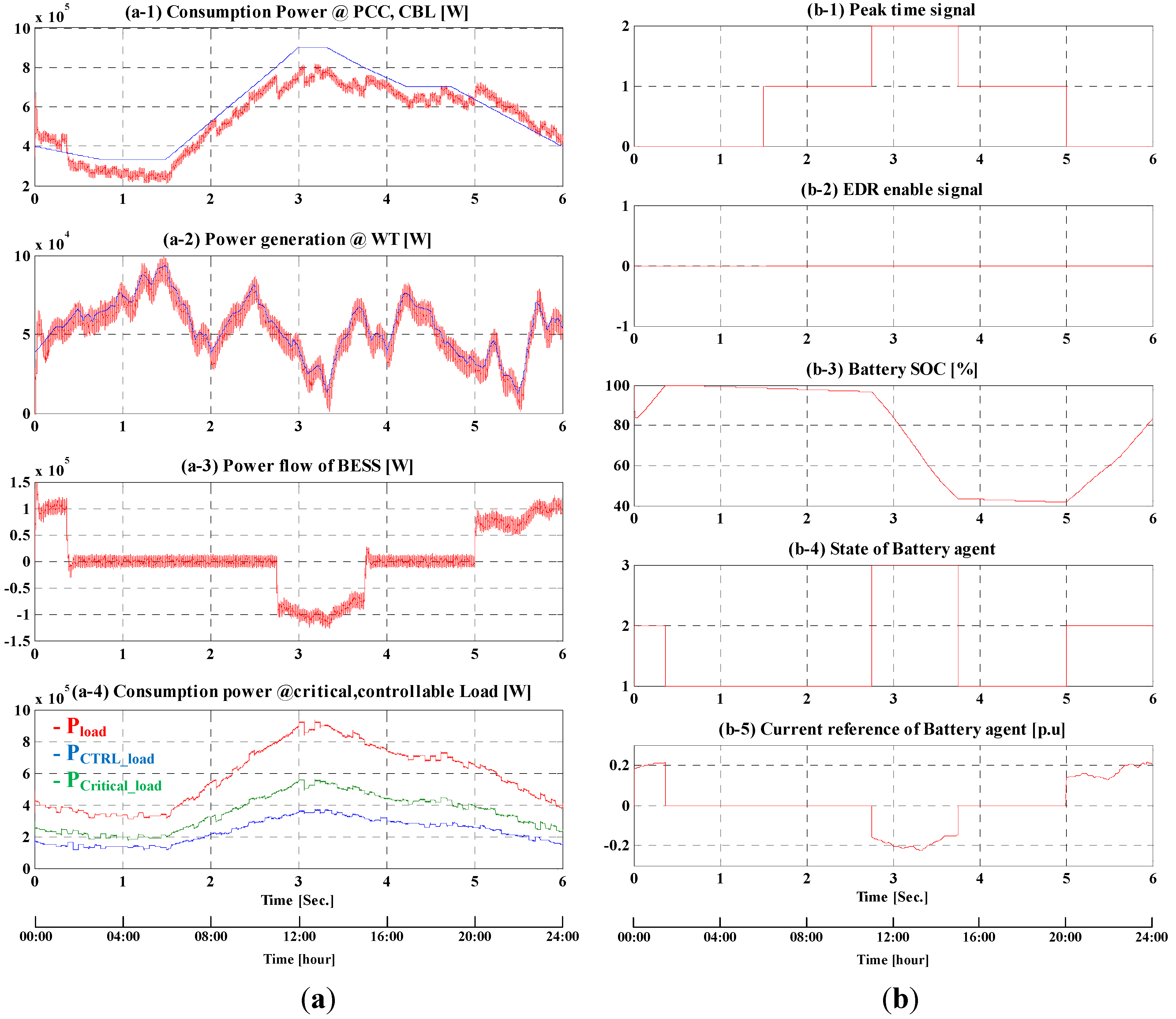
4.1. Case 1: Normal Operation

Case 1 simulates microgrid operation on a typical regular day when there is no EDR request from the grid. Figure 13 shows the simulation results of the microgrid operation. The left-hand-side graphs in Figure 13, which are from (a-1) to (a-4), show the power measurement at the important points such as the point of the common coupling (PCC) and the connection of the loads, WT, and BESS. The wind speed is randomly generated based on common daily pattern as shown in Figure 13(a-2). The total load consists of controllable loads and critical loads, which are also randomly generated based on common daily pattern in this simulation as shown in Figure 13(a-4).
Figure 13. Simulation results in case 1. (a) Power flow of microgrid; (b) Signal process of battery agent.
Energies 06 04956 g013
As mentioned in Section 3, the MGT operates as a backup generator during emergency conditions. Therefore, the MGT stops operating in this case because there is neither fault nor EDR request from the grid. The right-hand-side graphs in Figure 13 represent the data signal of the BESS agent. According to the amount of load, the peak time signal is divided into three periods such as peak-load, normal, and low-load periods. As shown in Figure 13(b-1), the low-load period, defined as “0” level, lasts from 20:00 to 6:00 and the peak period, defined as “2”, occurs from 11:00 to 13:00. Other times are set to the normal period which is set as “1”. Also, the positive value of Figure 13(b-5) means the charging operation of the BESS whereas the negative value of it represents the discharging operation.
In this case, the BESS operates to shave the loads during peak hours. Therefore, it charges during off-peak period and discharges during peak period. In addition, the battery agent manages charging and discharging of the BESS to keep the battery SOC between 30% and 100% depending on the CBL and wind speed. In this simulation, the initial value of the battery SOC is assumed as 85% and then, it charges up to 100% by following the fuzzy logic of state “2” of the state machine of the BESS as explained in Figure 6. When the BESS discharges, it also follows the fuzzy logic of state “3”. Figure 13(b-3) shows the variation of the battery SOC and Figure 13(b-4) shows the state of the BESS agent. Figure 13(b-5) shows the output current reference according to the fuzzy logics and Figure 13(a-3) is the resultant output power of the BESS.
After being fully charged, the battery agent is in state “1” before 11:00. At 11:00, the state of battery agent can be changed into state “3” with discharging the battery to support the power consumption of microgrid using fuzzy logic. When the wind speed is low and the load is high, the current reference for the discharging operation tends to grow high according to the fuzzy rules of state “3”. When the peak time signal is changed from “2” to “1”, the battery agent stops discharging operation and switches to standby mode. During the low-load period after 20:00, the BESS agent will change into state “2” and the BESS charges the battery according to charging fuzzy logic.

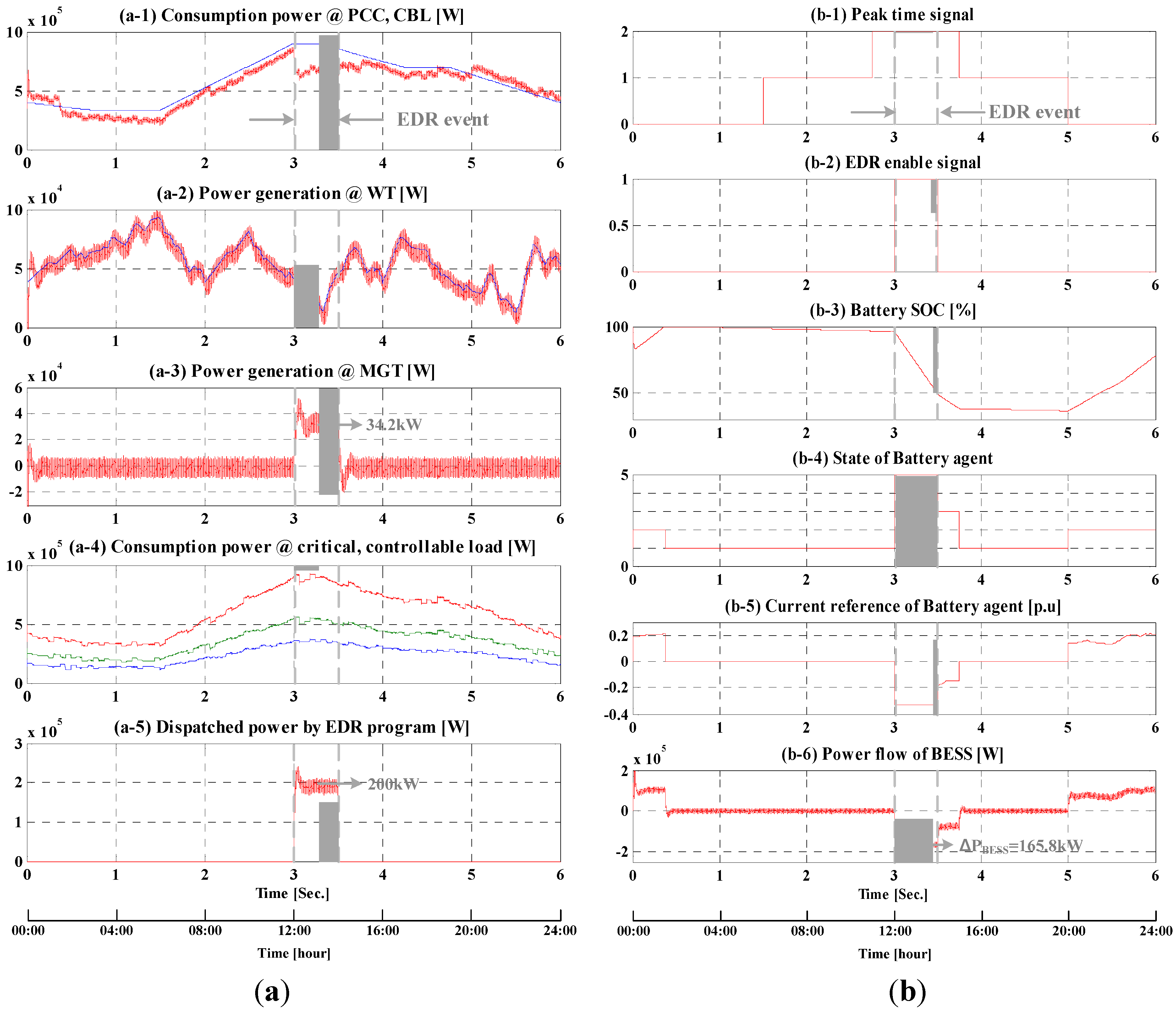
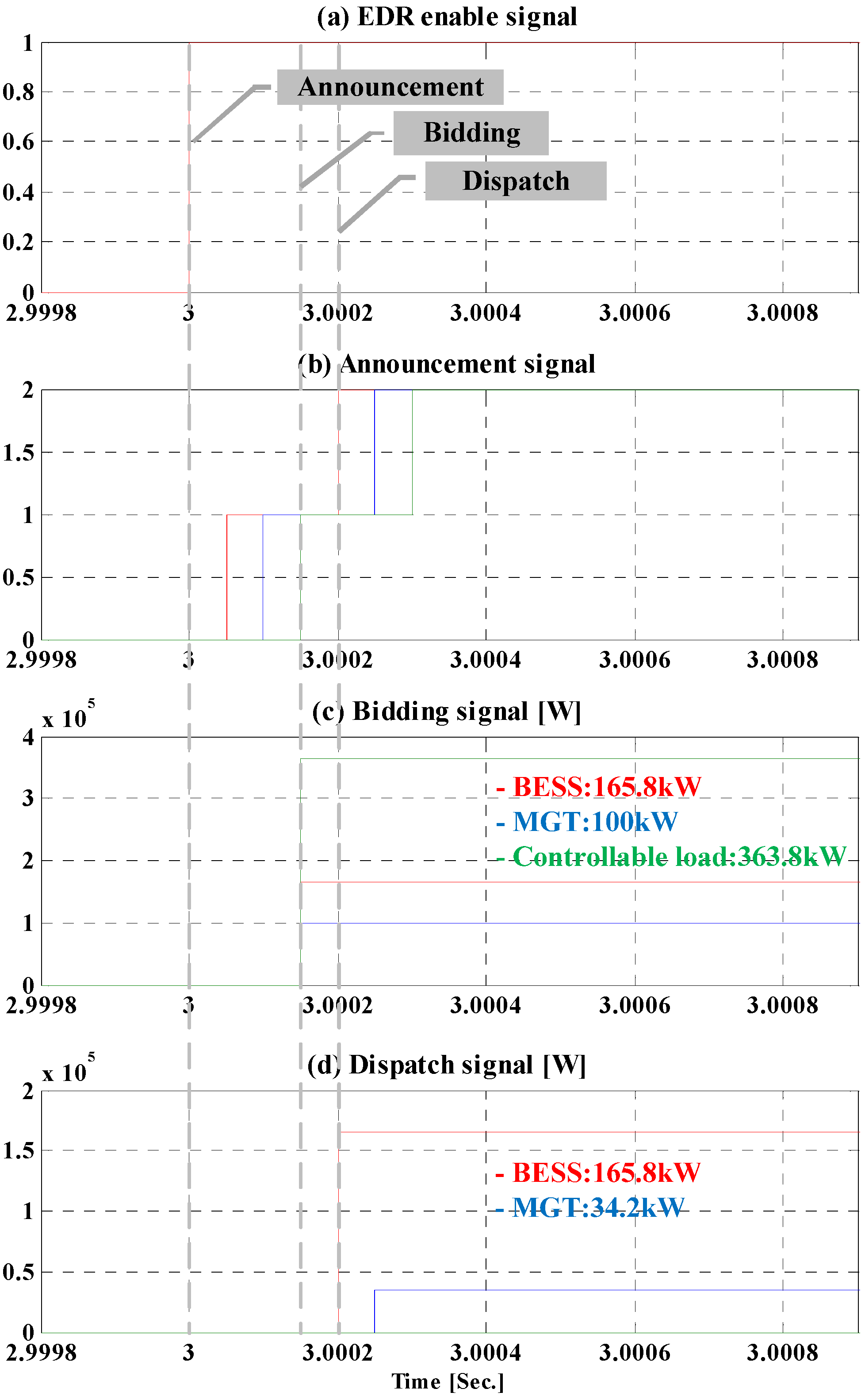
4.2. Case 2: EDR Event (Emergent Demand Reduction: 200 kW)

Sometimes, EDR events can be notified in advance a day or several hours before the actual events. Then, the MGCC informs the agent of the EDR event, which occurs at 12:00 pm and lasts for 2 h. Figure 14 shows the communication procedure between the MGCC and the agents following the CNP in the EDR event. When the LA requests for EDR participation to the MGCC, the amount of load reduction (QEDR) and the monetary incentive is determined by contracts. Then, the MGCC informs the agents of the EDR information such as QEDR and the incentive. Then, the agents turn in their available bids including the EDR participation power and the incentive to the MGCC in the second step. When the total DR participation energy is sufficient compared to QEDR, the optimal amount of participation can be distributed and the priority is determined by their submitted incentive price.
In this paper, the BESS has the first priority of EDR participation because the BESS can store energy when the electricity rate is lowest. The MGT has the second priority and then, the controllable loads and critical loads are next.
Figure 15 and Figure 16 show the simulation results of case 2. The initial condition is the same as case 1. After being fully charged, the BESS stops charging and waits for participating in the EDR event with the maximum available bid. As shown in Figures 15(b-1) and (b-5), unlike case 1, the loads are heavy before 11:00 am but the BESS stays in standby mode until the EDR event occurs from 12:00 pm to 14:00 pm as colored in gray in Figure 15.
Figure 14. Decision making procedure for dispatching EDR participation power.
Energies 06 04956 g014
Figure 15. Simulation results in case 2. (a) Power flow of microgrid; (b) Signal process of BESS agent.
Energies 06 04956 g015
Figure 16. Decision making procedure for EDR power dispatch in case 2.
Energies 06 04956 g016
The LA requests the MGCC to reduce the load as much as 200 kW at 12:00 pm in this case. Then, the MGCC informs the agent of the DR information. The maximum available bids of the BESS can be determined by using Equation (9) as:
P B E S S E D R = P B E S S R a t e d ( S O C % 30 % 100 % ) 1 h o u r P B E S S I n i t i a l   = 500 k W h ( 96.34 % 30 % 100 % ) 1 2 h o u r 0 W   165.8 k W
were SOC% is little bit lower than 100% due to the natural discharge of the BESS. Because the BESS was a standby mode before the EDR event, the battery agent can bid the maximum power without considering the compensation power of peak loads.
The MGT agent can bid up to the rated power of MGT, 100 kW. In this simulation, the CBL values of controllable and critical loads are randomly set to 364 kW and 600 kW respectively. Thus, the load agent can bid up to the size of the controllable load as much as 364 kW.
Now, the MGCC receives the bids from the agents as much as 629.8 kW in total: 165.8 kW from the BESS, 100 kW from the MGT, and 364 kW from the controllable load. Then, the total EDR participation power is enough compared to the request load reduction, 200 kW. The MGCC can assigns the amount of participation of each agents based on the incentive price submitted by the agents. As mentioned above, the MGCC can dispatch the EDR participation power as 165.8 kW for the BESS and 34.2 kW for the MGT. Since the BESS and the MGT can cover the requested EDR power, it is not needed to cut out the loads.
The communication signal of this decision making procedure of proposed EMS can be seen in Figure 16. When the EDR event occurs, the announcement signal of the MGCC changes from “0” to “1” as shown in Figure 16b. If the total sum of the bids from the agents is larger than the requested EDR power, the announcement signal changes into “2”. If not, the announcement signal will keep its signal level to “1”. At the end of decision making procedure, the MGCC informs the agents of the optimal participation value as shown in Figure 16d.
As a result, the total power consumption of the microgrid at the PCC is reduced by 200 kW as shown in Figure 15(a-1) and (a-5). Because the WT is controlled in MPPT mode in the simulation, it cannot participate in the EDR event and there is no change in the power output of the WT as shown in Figure 15(a-2). During the EDR event, it is shown that the MGT generates 34.2 kW more and the BESS generates 165.8 kW in Figure 15(a-3) and (b-6).

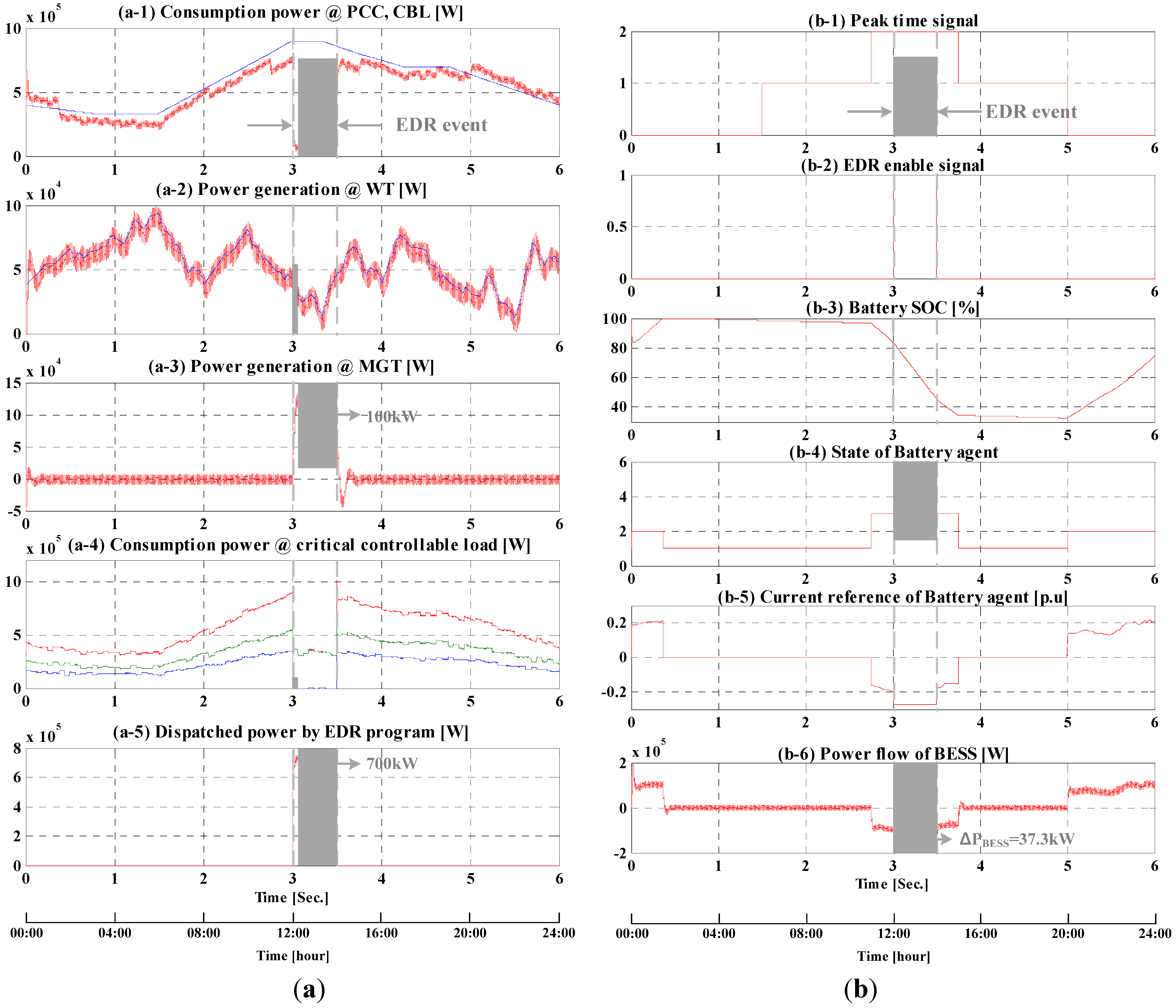
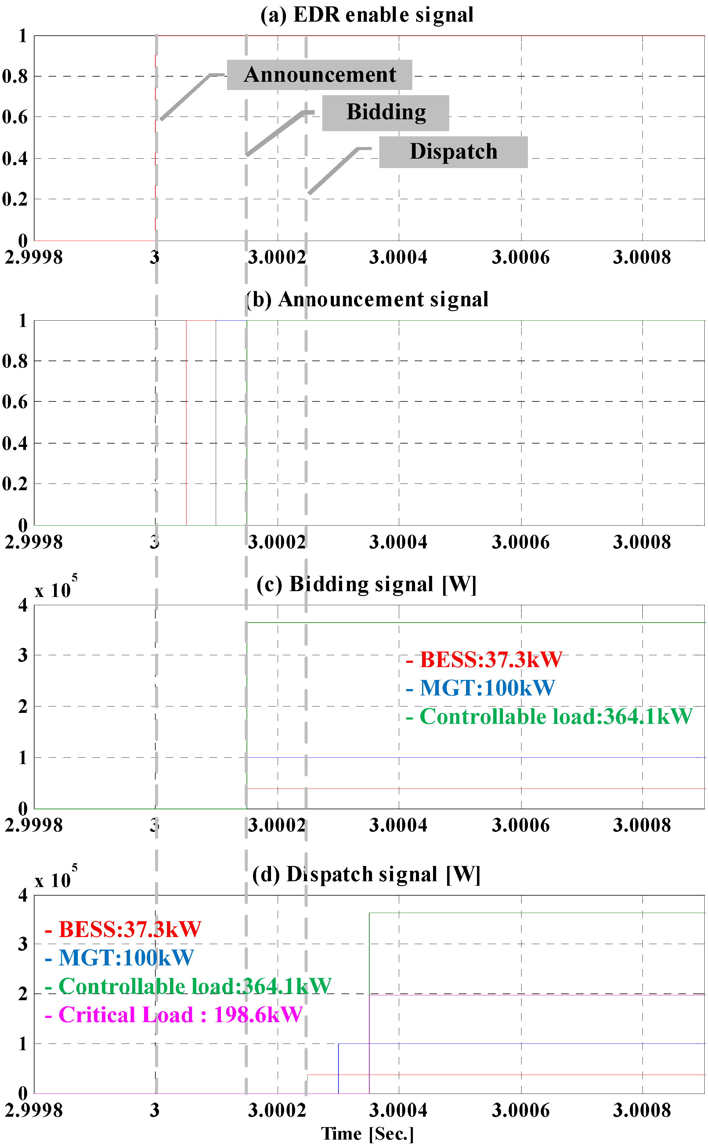
4.3. Case 3: EDR Event (Emergent Demand Reduction: 700 kW)

Case 3 assumes severe conditions for the EDR events. In this case, the EDR event occurs suddenly at 12:00 pm without prior notice and lasts for 2 h. In addition, emergent demand reduction is also requested severe as much as 700 kW, which is larger than the size of the MGT and the BESS. Figure 17 and Figure 18 show the simulation results of case 3.
The initial condition is also the same as cases 1 and 2. When the loads are heavy from 11:00 to 15:00, the BESS tries to discharge to shave the loads according the fuzzy logic of state “3”. When the EDR event occurs at 12:00 pm, the MGCC informs the agent of the EDR information QEDR as much as 700 kW. The available bids of the BESS can be determined by using Equation (9) as:
P B E S S E D R = P B E S S R a t e d ( S O C % 30 % 100 % ) 1 h o u r P B E S S I n i t i a l   = 500 k W h ( 84.25 % 30 % 100 % ) 1 2 h o u r 98.375 k W   37.3 k W
Because the BESS was discharging before the EDR event as much as 98.375 kW to compensate the peak loads, it cannot participate much on the EDR event. The MGT agent can bid 100 kW and the load agent bids 364 kW of controllable load as shown in Figure 16c. The MGCC receives the bids from the agents as much as 501.3 kW in total after the first-round of the CNP procedure. However, the total EDR participation power is less than the requested EDR power, 700 kW. To meet the EDR request, the MGCC decides to reduce some part of the critical loads as much as 198.7 kW.
Figure 17. Simulation results in case 3. (a) Power flow of microgrid; (b) Signal process of BESS agent.
Energies 06 04956 g017
Figure 18. Decision making procedure for EDR power dispatch in case 3.
Energies 06 04956 g018

5. Conclusions

This paper presents autonomous and intelligent energy management schemes of microgrids applying the concept of multi-agent systems. It also elaborates the details of the microgrid modeling and energy management schemes. The developed energy management system consists of MGCC and multiple agents for distributed control of microgrids. To control the output power of the DERs, the intelligent agents are integrated into the simulation model. Cases for emergency demand response have been tested to examine the operation of microgrid. The agents are programmed to flexibly talk to the other agents and the MGCC via the CNP and then finally find a solution of each unit corresponding to a certain EDR request for peak shaving. More efficient intelligent algorithms for optimization and coordination will be developed for the multi-agents in the future work.

Acknowledgments

This work was supported by the Ministry of Knowledge Economy, Korea, under the Information Technology Research Center support program (NIPA-2012-H0301-12-2007) supervised by the National IT Industry Promotion Agency and Basic Science Research Program through the National Research Foundation of Korea funded by the Ministry of Education, Science and Technology (NRF-2011-0014872).

Conflicts of Interest

The authors declare no conflict of interest.

References

  1. Chowdhury, S.; Chowdhury, S.P.; Crossley, P. Microgrids and Active Distribution Networks; The Institution of Engineering and Technology (IET): London, UK, 2009. [Google Scholar]
  2. Hatziargyriou, N.; Asano, H.; Iravani, R.; Marnay, C. Microgrids. IEEE Power Energy Mag. 2007, 5, 78–94. [Google Scholar] [CrossRef]
  3. Kang, H.; Yoo, C.; Chung, I.; Won, D.; Moon, S. Intelligent coordination method of multiple distributed resources for harmonic current compensation in a microgrid. J. Electr. Eng. Technol. 2012, 7, 834–844. [Google Scholar] [CrossRef]
  4. Chung, I.; Liu, W.; Cartes, D.; Collins, E.; Moon, S. Control methods for multiple distributed generators in a microgrid system. IEEE Trans. Ind. Appl. 2010, 46, 1078–1088. [Google Scholar] [CrossRef]
  5. Kim, J.; Nam, Y.; Hahn, T.; Hong, H. Demand Response Program Implementation Practices in Korea. In Proceedings of the 18th IFAC World Congress, Milano, Italy, 28 August–2 September 2011.
  6. Yoo, T.; Kwon, H.; Lee, H.; Rhee, C.; Yoon, Y.; Park, J. Development of Reliability Based Demand Response Program in Korea. In Proceedings of the IEEE PES Innovative Smart Grid Technologies, Anaheim, CA, USA, 17–19 January 2011.
  7. Teleke, S.; Baran, M.E.; Bhattacharya, S.; Huang, A.Q. Rule-based control of battery energy storage for dispatching intermittent renewable sources. IEEE Trans. Sustain. Energy 2010, 1, 117–124. [Google Scholar] [CrossRef]
  8. Lagorse, J.; Simoes, M.; Miraoui, A. A multiagent fuzzy-logic-based energy management of hybrid systems. IEEE Trans. Ind. Appl. 2009, 45, 2123–2129. [Google Scholar] [CrossRef]
  9. Ackermann, T. Wind Power in Power Systems; John Wiley & Sons: Chichester, UK, 2005. [Google Scholar]
  10. Albadi, M.H.; El-Saadany, E.F. Demand Response in Electricity Markets: An Overview. In Proceedings of the 2007 IEEE Power Engineering Society General Meeting, Tampa, FL, USA, 24–28 June 2007; pp. 1–5.
  11. Aalami, H.; Yousefi, G.R.; Moghadam, M.P. Demand Response Model Considering EDRP and TOU Programs. In Proceedings of the Transmission and Distribution Conference and Exposition, Chicago, IL, USA, 21–24 April 2008; pp. 1–6.
  12. Teodorescu, R.; Liserre, M.; Rodriguez, P. Grid Converters for Photovoltaic and Wind Power Systems; Wiley: Chichester, UK, 2011. [Google Scholar]
  13. Wooldridge, M. An Introduction to Multiagent Systems; John Wiley and Sons: Chichester, UK, 2009. [Google Scholar]
  14. Lagorse, J.; Paire, D.; Miraoui, A. A multi-agent system for energy management of distributed power sources. Renew. Energy 2010, 35, 174–182. [Google Scholar] [CrossRef]
  15. Logenthiran, T.; Srinivasan, D.; Khambadkone, A.M. Multi-agent system for energy resource scheduling of integrated microgrids in a distributed system. Electr. Power Syst. Res. 2011, 81, 138–148. [Google Scholar] [CrossRef]
  16. Kim, H.; Kinoshita, T. A multiagent system for microgrid operation in the grid-connected mode. J. Electr. Eng. Technol. 2010, 5, 246–254. [Google Scholar] [CrossRef]
  17. Yoo, C.; Choi, W.; Chung, I.; Won, D.; Hong, S.; Jang, B. Hardware-in-the-Loop Simulation of DC Microgrid with Multi-Agent System for Emergency Demand Response. In Proceedings of the IEEE Power and Energy Society General Meeting, San Diego, CA, USA, 22–27 July 2012; pp. 1–6.
  18. Oh, S.; Yoo, C.; Chung, I.; Won, D. Hardware-in-the-loop simulation of distributed intelligent energy management system for microgrids. Energies 2013, 6, 3263–3283. [Google Scholar] [CrossRef]

