Article

Hardware-in-the-Loop Simulation of Distributed Intelligent Energy Management System for Microgrids

1
School of Electrical Engineering, Kookmin University, 861-1, Jeongneung-dong, Seongbuk-gu, Seoul 136-702, Korea
2
School of Electrical Engineering, Inha University, 100 Inha-ro, Nam-gu, Incheon 402-751, Korea
*
Author to whom correspondence should be addressed.
Energies 2013, 6(7), 3263-3283; https://doi.org/10.3390/en6073263
Submission received: 6 May 2013 / Revised: 19 June 2013 / Accepted: 21 June 2013 / Published: 3 July 2013

Abstract

:
Microgrids are autonomous low-voltage power distribution systems that contain multiple distributed energy resources (DERs) and smart loads that can provide power system operation flexibility. To effectively control and coordinate multiple DERs and loads of microgrids, this paper proposes a distributed intelligent management system that employs a multi-agent-based control system so that delicate decision-making functions can be distributed to local intelligent agents. This paper presents the development of a hardware-in-the-loop simulation (HILS) system for distributed intelligent management system for microgrids and its promising application to an emergency demand response program. In the developed HILS system, intelligent agents are developed using microcontrollers and ZigBee wireless communication technology. Power system dynamic models are implemented in real-time simulation environments using the Opal-RT system. This paper presents key features of the data communication and management schemes based on multi-agent concepts. The performance of the developed system is tested for emergency demand response program applications.

1. Introduction

Microgrids have recently emerged as a new paradigm for power distribution networks that can host multiple distributed energy resources (DERs) and especially, renewable energy resources. DERs in microgrids are usually integrated through power-electronic converters that can effectively control power system parameters such as voltages, currents, and real and reactive powers. Because the power flow at the point of common coupling can be precisely controlled by power converters, microgrids can be designed as autonomous independent cells in power system operation [1]. This means that microgrids can act as an independent controllable source or load whose power input/output can be controlled. Therefore, contracts for energy generation/consumption or ancillary services between microgrids and the grids are possible [2,3].
Generally, the entities of microgrids have uncertainties in their power output. For example, power generation of renewable energy resources may be affected by environmental conditions. Power consumption of loads is influenced by the propensities of individual customers. Therefore, microgrids need to compensate the uncertainties with state-of-the-art control schemes. This paper focuses on a distributed intelligent management system (DIMS) for a microgrid based on the concept of intelligent agents and their mesh networks, referred to as a multi-agent system (MAS) [4,5,6,7,8]. The idea of MAS application is quite timely due to current increasing needs for smart energy management technologies. Under the MAS environment, individual intelligent agents can determine power control strategies on behalf of microgrid entities such as DERs or loads. To this end, the agents need to measure local information and communicate with other agents spontaneously. They can make decisions with artificial intelligence by negotiating and cooperating with other agents. The microgrid central coordinator (MGCC) acts as a portal system between the independent system operator (ISO) and individual agents and an arbiter who can mediate and control the agents. The details of the DIMS are elaborated in the paper.
The major application of the developed microgrid DIMS is the emergency demand response (EDR) program designed by Korea Power Exchange (KPX). When the grid power reserve diminishes quickly, the grid operator needs an emergent load reduction for stable operation. This procedure is called demand response. One of the popular demand response programs is emergency demand response (EDR) that offers incentives to the customers who instantly reduce their load [9]. In this paper, the control objective of the MAS-based microgrid control is defined to find the optimal condition for EDR of KPX. Decision-making procedure based on MAS configuration is presented in this paper.
This paper presents details of the hardware-in-the-loop simulation (HILS) system of MAS-based DIMS for a microgrid and the improvements compared to our previous results [10]. The power system model of the microgrid including a battery energy storage system (BESS), a micro-gas turbine (MGT), and a smart load is implemented in a real-time simulator named Opal-RT. The hardware devices of intelligent agents are developed using 16-bit Freescale microcontrollers. The microgrid simulation model and the agent hardware are interfaced via real-time HILS setup. The control commands of agents are delivered through interface boards using a controller area network (CAN) protocol. The communication between agents is provided by ZigBee modules, which is famous for being a low-cost low-power wireless communication technology. Agents can communicate with other agents as well as MGCC in either peer-to-peer or one-to-many communication mode using the ZigBee protocol. The performance of the developed DIMS is verified by the HILS experiments.

2. Microgrid Configuration and Operation

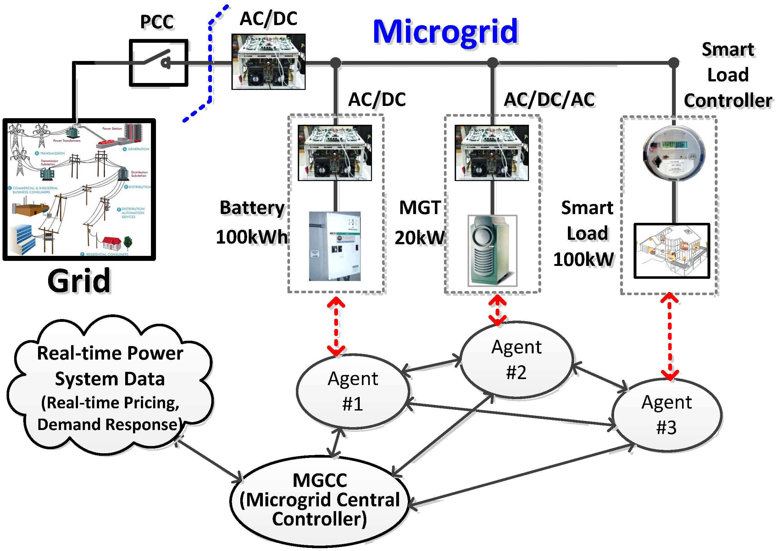
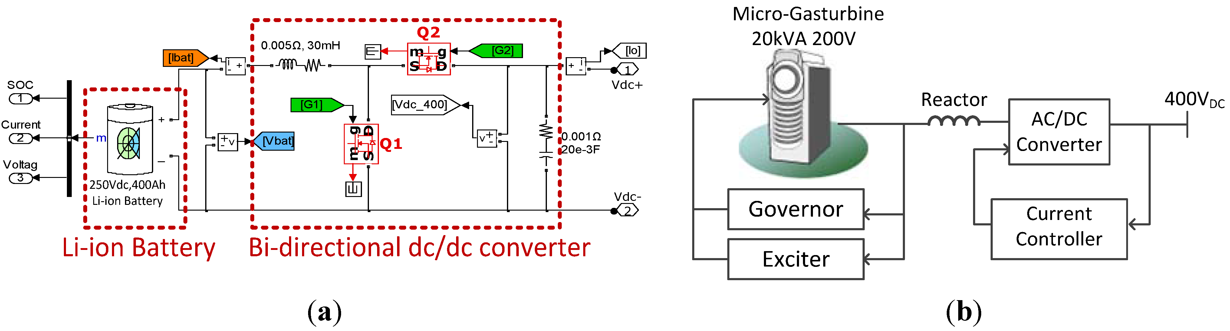
2.1. Microgrid Model

Figure 1 illustrates a single-line diagram of a microgrid that contains a battery energy storage system (BESS), a micro-gas-turbine (MGT), and smart loads. The microgrid is designed as a low-voltage DC system of which nominal voltage is 400 V. Microgrid entities such as BESS, MGT and smart loads are controlled by intelligent agents as illustrated in Figure 1. The MGCC coordinates multiple agents and communicates with the grid operators as explained in the Introduction.
Figure 1. Configuration of microgrid with MAS-based control system.
Energies 06 03263 g001
BESSs can compensate instant power mismatches introduced by renewable energy resources or loads. Figure 2a illustrates the equivalent model the BESS that uses a Li-ion battery model and a bi-directional DC-DC converter. The BESS operates in 250V DC and its rated capacity is 400 Ah, which can store 100 kWh of electric energy. The bi-directional boost converter is controlled in continuous current mode that can extend the lifespan of the battery. The maximum discharge rate of general Li-ion batteries is known as 4.0 C-rate, but it is recommended to confine the discharge rate below 1.0 C-rate in order to keep the battery in efficient shape. In the simulation model, the BESS is designed to charge electricity about 0.1 C-rate during off-peak periods and discharge electric energy at 0.2 C-rate under peak loading conditions. Charging and discharging controls are also determined by the level of the state-of-charge (SOC) of the battery. The SOC should be maintained between 20% and 100% during the normal state. If the SOC is lower than 20%, the BESS must stop discharging immediately and needs to be charged whenever surplus energy is available.
The MGT is modeled as a synchronous generator, an AC/DC rectifier and a DC/AC grid-inverter as illustrated in Figure 2b. The rated power of the MGT is set at 20 kW.
Figure 2. Configuration of BESS and MGT. (a) Configuration of BESS; (b) Configuration of MGT.
Energies 06 03263 g002
In order to participate in the EDR program, loads must be classified into either controllable loads or sensitive loads. Controllable loads are the loads that can be turned off during the emergent conditions. Heaters or air conditioners for general purposes are good examples of controllable loads. Sensitive loads require reliable electricity all the time. Process controllers and medical equipment can be representative examples of sensitive loads.
The dynamic model of the microgrid is implemented in the real-time simulation environment using Opal-RT RT-LABTM, which is designed to realize the real-time simulation on clusters of standard multi-core CPU computers so that the overall simulation can be accelerated. The simulation time and accuracy of the microgrid can also be improved by using the power system solver and toolboxes of RT-LAB [11]. Figure 3 shows the real-time simulation model with the Opal-RT system. Figure 4 shows the real-time simulation results of charging and discharging operations of the BESS in the developed microgrid model. It can be noted that the SOC of the BESS changes according to the charging and discharging actions.
Figure 3. Real-time simulation model development using RT-LAB.
Energies 06 03263 g003
Figure 4. Real-time simulation results of battery charging and discharging operations. (a) Battery DC voltage; (b) Battery output current; (c) State of charge.
Energies 06 03263 g004

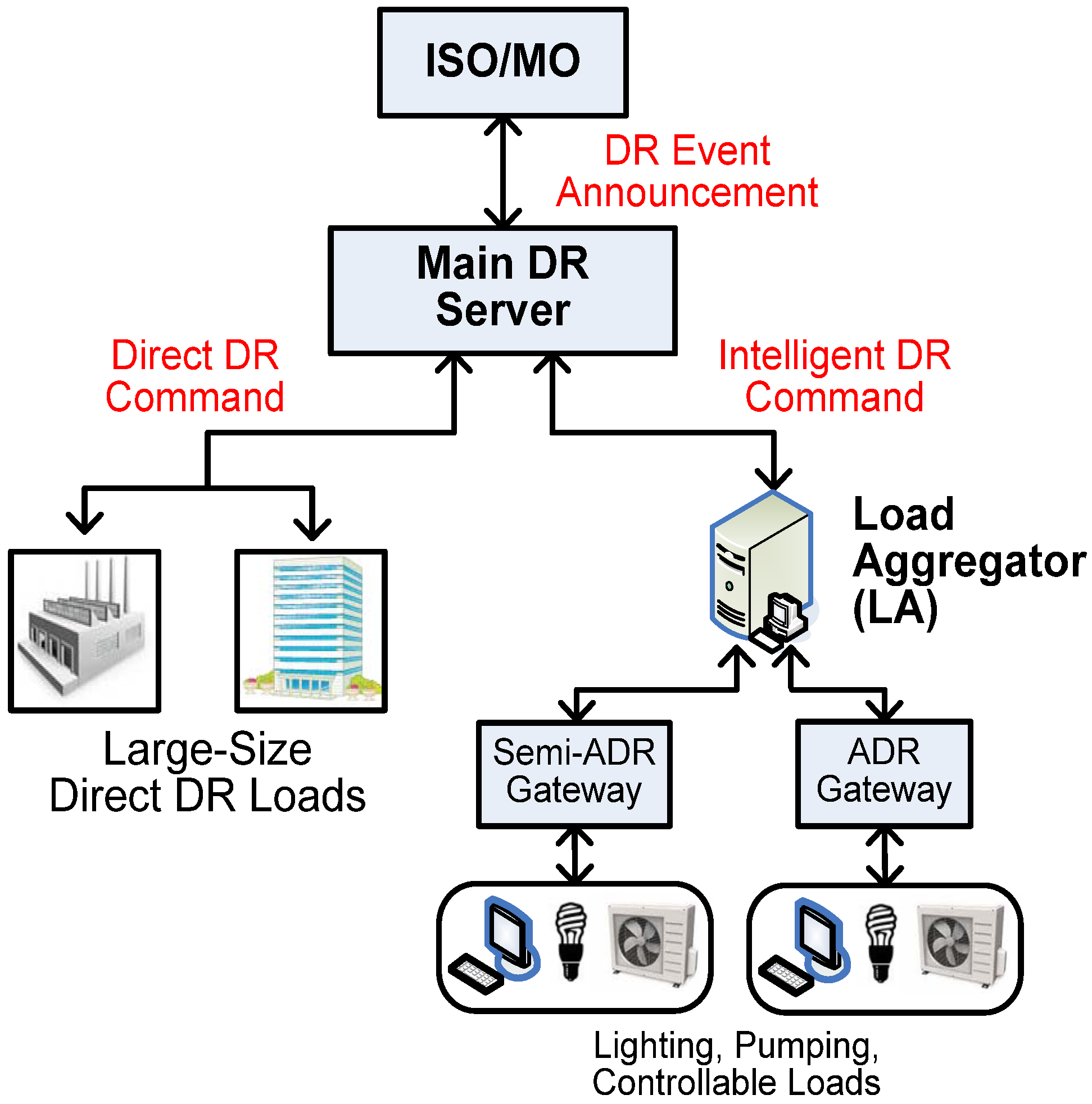
2.2. Emergency Demand Response

Demand response (DR) programs can be defined as the changes in electricity consumption of loads during the peak loading period [12,13,14,15]. DR programs are divided into two groups such as incentive-based and price-based programs. An emergency demand response (EDR) program is a representative incentive-based program. The participants in EDR program receive monetary incentives for their load reduction in response to the request of the ISO. Price-based programs such as Time-of-Use and Critical-Peak-Pricing programs are based on dynamic pricing rates in which electricity prices change during a day. The participants will reduce energy consumption to avoid expensive electric bills.
Figure 5 illustrates the configuration of the EDR programs developed by Korea Power Exchange (KPX) that consists of two markets [12]. One is Direct DR market for large-size loads and the other is Intelligent DR market for medium and small-size loads. This paper focuses on the Intelligent DR market because it seems to be more relevant for microgrids. In the Intelligent DR market, medium-size electric customers who can reduce overall power consumption between 100 kW and 3,000 kW can make a direct contract with KPX or through load aggregators (LAs). Small-size customers, whose load reduction capability is less than 100 kW, must contract with LAs to participate in the DR program. The incentives consist of the capacity price and the performance incentive. The capacity price pays for the contract size of total load reduction (kW) and the performance incentive is for the delivery of the contract (kWh). The average values of the capacity price and the performance incentive in 2013 are about 64,000 KRW/kW and 550 KRW/kWh, respectively, where KRW stands for Korea monetary unit (won). It should be noted that the performance incentive is about five times higher than the average electricity price of Korea power market (about 93 KRW/kWh in 2012).
According to the Intelligent EDR program, KPX must limit the maximum number of EDR events to within 30 times a year and 2~3 h a day. Participants must install smart meters to measure power consumption and send the information to the LA servers every 15 minutes. The LAs calculate the actual load reduction by calculating the difference between the measured load consumption and the Customer Base Line (CBL). The CBL is calculated every day based on the past 10-day power consumption data by using weighted averaging windows [12,13]. The customers can be divided into two groups such as automatic DR (ADR) loads and semi-ADR loads according to the communication channel. ADR loads must achieve load reduction within 10 minutes while semi-ADR loads reduce the power consumption within 30 minutes. The purpose of this paper is to design the microgrid to participate in the Intelligent DR program of KPX through ADR gateways.
Figure 5. Conceptual diagram of data communication for KPX’s demand response program.
Energies 06 03263 g005

3. Development of Microgrid DIMS

The developed microgrid DIMS consists of the MGCC and multiple agents as shown in Figure 1. The MGCC provides graphic user interface (GUI) for display and parameter settings and also control functions that can coordinate multiple agents. The agents can cooperate with other agents as well as the central coordinator if necessary. The information between agents and the coordinator can be transferred through wireless communication based on ZigBee protocol that is one of the promising solutions for short-distance wireless personal area networks. The target systems of the agents such as BESS, MGT and smart load are developed as simulation models in the real-time simulator. The interfaces between the agents and the target systems are implemented via the CAN 2.0B protocol.

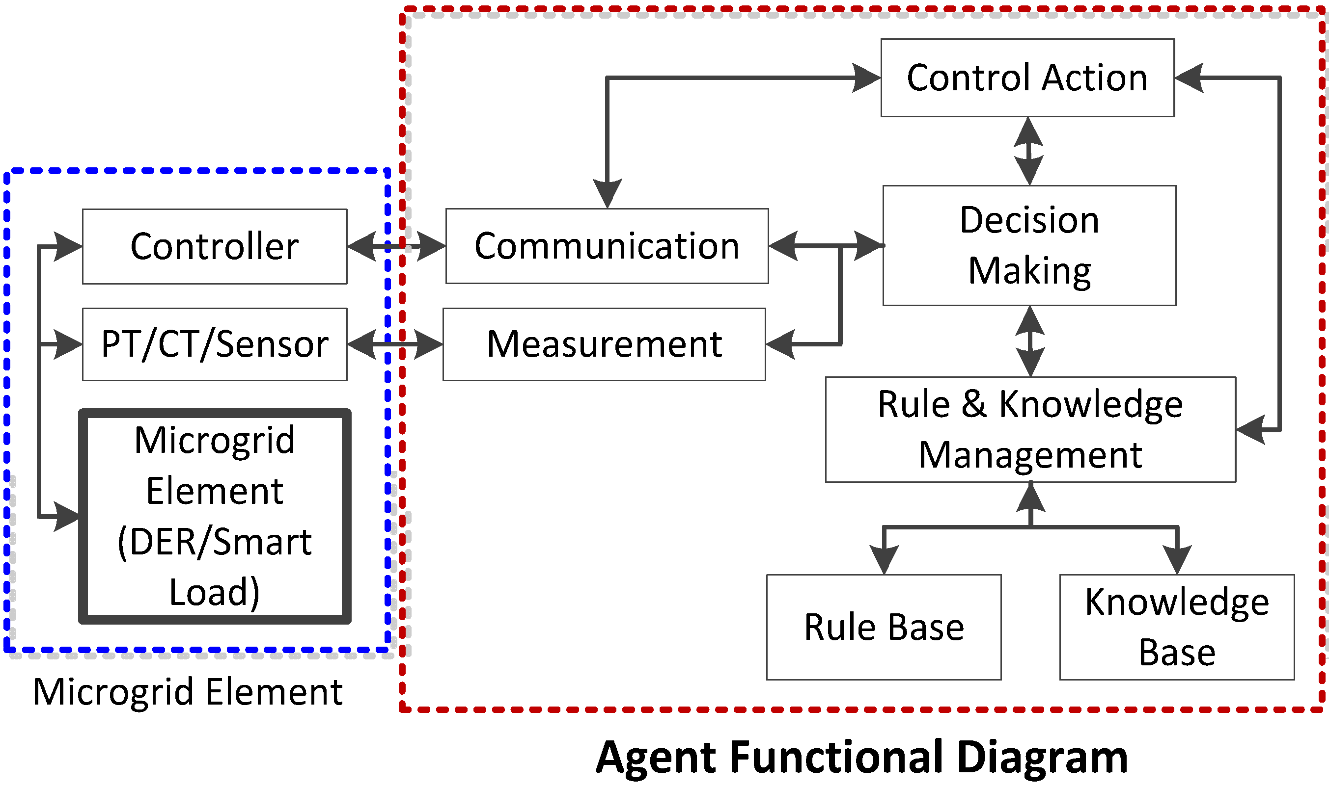
3.1. Intelligent Agents
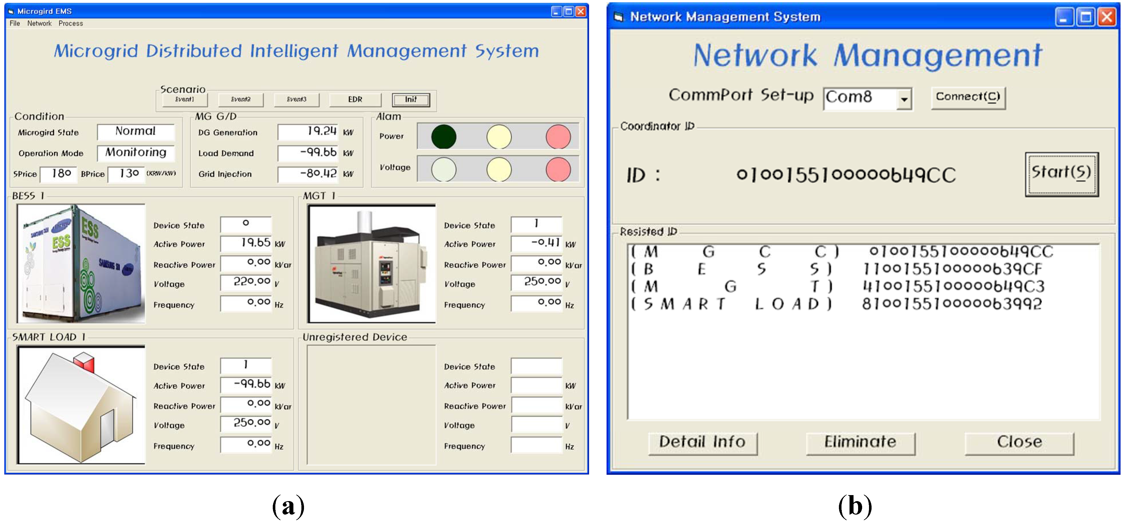
Intelligent agents have reactive, proactive, and social abilities so that they can react to the environmental changes, follow the final goal, and interact between other agents in a cooperative or competitive manner [4]. Reference [5] explains that agents should have fundamental modules such as data collection, communication, decision-making, action implementation, and knowledge management. Figure 6 illustrates the functional diagram of agents for microgrid application. The agents can obtain the information such as the rated values and the states of the target systems by monitoring the local system. When the agents receive EDR requests from the MGCC, they should make a proposal based on the knowledge-based intelligent algorithms.
Figure 6. Functional diagram of agents.
Energies 06 03263 g006
Compared to our previous results presented in [10], the hardware devices of the intelligent agents are upgraded from AVR 8-bit microcontrollers (Atmega128) to Freescale 16-bit microcontrollers (HCS12XDP512), so the computational performance is improved from 16 MIPS to 80 MIPS in the upgraded hardware and the precision of data arithmetic operations has been significantly improved. In addition, memory for the agent program has been extended from 4 Kbyte SRAM and 128 Kbyte Flash memory to 32 Kbyte SRAM and 512 Kbyte Flash memory. Figure 7 shows a developed agent hardware device using a Freescale HCS12XDP51216-bit microcontroller and a ZigBee module (FZ750BC).
CAN 2.0B was used as standard communication protocol between agents and target devices. This protocol has a data rate of up to 1 Mbps and up to 8-bytes of data length. The communication between agents and the devices basically is established in one-to-one communication mode. The control signals are transferred to the target devices through CAN interface card in the Opal-RT system. In the previous set-up using the Atmega128, the data exchange between agents and the controlled DER units and load units was implemented via analog I/O channels so that they were prone to be affected by external noises [10]. However, in the new setup, HCS12XDP512 microcontrollers can support CAN 2.0 protocol so that the digital data communication is possible between the agent and the controlled units. Therefore, the agents and the units can transfer more accurate information with faster data exchange rate and lower communication error.
Figure 7. Agent hardware using a microcontroller with ZigBee module.
Energies 06 03263 g007

3.2. MGCC

The MGCC has three major functions: (1) to manage local agents and monitor their states and power system data in real-time; (2) to communicate with the upper-level control systems such as LAs or ISOs; (3) to coordinate multiple agents to achieve the overall goal of the microgrid operation. Compared to the previous development [10], new additional functions were implemented in the MGCC program such as autonomous agent registration function using plug-and-play concept, real-time data monitoring function, communication network management function and additional user interfaces.
The MGCC provides a graphic user interface (GUI) that shows the real-time monitoring data, the states of the microgrid, the information of DERs and loads in service, and network information. Figure 8 shows some sample screens of the GUI program of the developed DIMS. Figure 8a displays the monitoring data such as real and reactive powers, voltage and frequency. Figure 8b shows the network information and identification of the connected DERs and loads.
To efficiently manage the DERs in the microgrid, the MGCC provides Plug-and-Play functionality that can automatically register and withdraw the agents in the DIMS. Usually, microgrids are composed of renewable energy resources and small-scale distributed generators that may be disconnected from the microgrid for a variety of reasons such as environmental conditions and economic decisions. Therefore, the Plug-and-Play function can help the MGCC flexibly respond to the changes in the microgrid configuration. When a new agent wants to register in the microgrid DIMS, it needs to transmit its MAC address, device ID and target system information to the MGCC. Then, the MGCC checks whether it is new or already-registered by comparing the MAC address and device ID. If it is a new one, the MGCC assigns an agent number to the agent. Finally, the MGCC informs the participation of a new agent to the other agents.
Figure 8. Graphic User Interface of MGCC. (a) Real-time monitoring data display; (b) Network information.
Energies 06 03263 g008
The MGCC communicates with the local agents to respond to the EDR request optimally. The detailed protocol in the communication between the MGCC and the agents follows the Contract Net Protocol (CNP). The CNP provides a formal procedure in the coordination procedure in MAS-based management systems [15]. The contract between the MGCC and agents can be reached by the process of decision-making and interaction based on two-way communication. Figure 9 illustrates the concept of the CNP based decision-making procedure.
Figure 9. Concept of CNP.
Energies 06 03263 g009
The overall procedure starts when the main grid requests for certain actions such as demand response. In the CNP procedure, decision-making processes can be found both in the MGCC and the agent side. Agents should decide how to participate in the present task by evaluating the detailed conditions of the task and check local information such as generation cost, state-of-charge of a battery, energy market price, and so on. The MGCC decides the overall operation scheme for a microgrid after receiving the bids from the agents. If the bids from the agents are not enough to meet the request from the grid, the MGCC can modify the task conditions to lead additional participation from agents or command agents to follow its decision.

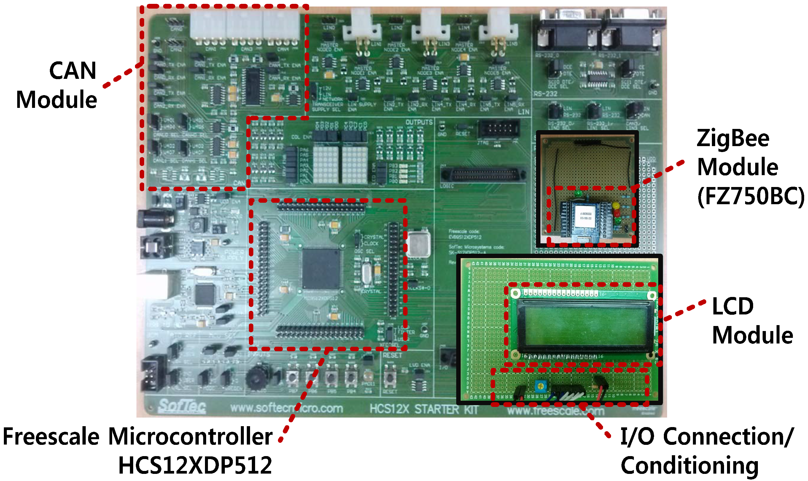
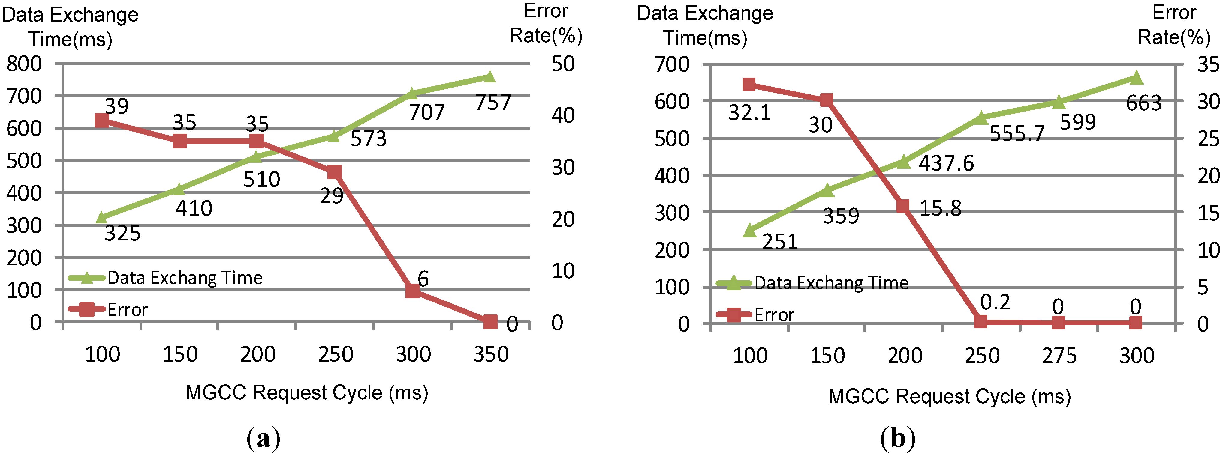
3.3. Communication Network
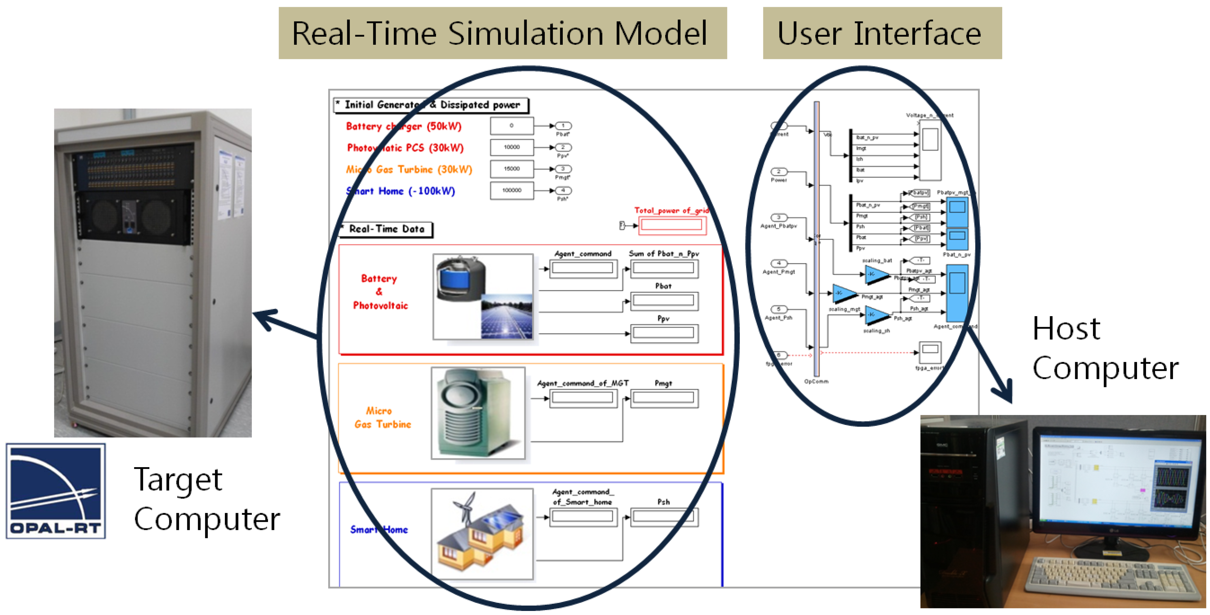
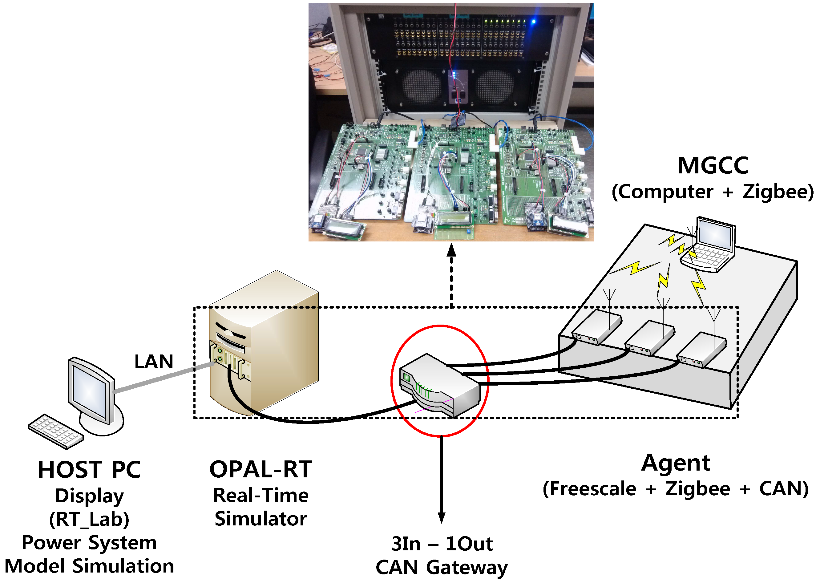
The developed microgrid DIMS uses the ZigBee protocol that is a standardized wireless communication technology for the application layer based on PHY/MAC layer following IEEE Standard 802.15.4. This protocol can transfer data at a speed of 250 kbps and maximally connect about 65,000 devices to one channel with a mesh network. ZigBee is used in this paper as a means of providing low-power economic communication technologies for multi-agent systems. Actually, the range of ZigBee network is about 100 m. However, maximally five times multi-hop wireless communication is possible in ZigBee communication so that it allows us to network microgrids up to several hundred meters away. ZigBee network can securely collect data from more than twenty nodes in 2 s [16]. Thus, ZigBee network is enough for energy scheduling, demand response and secondary control of frequency control in power systems. However, if faster response or wider range coverage is needed in the microgrid communication within a few seconds, more expensive and sophisticated communication means should be built such as the internet, CDMA or PLC-based network [17,18,19].
Compared to other communication solutions, ZigBee is advantageous for short-distance sensor networks such as residential or commercial applications because of its high security, low power consumption, and so on. Because there is no physical line connection between agents and the MGCC in a ZigBee network, the configuration of the developed DIMS can be compact and flexible.
Figure 10 shows the data packet design of ZigBee communication in the microgrid DIMS, which contains four types of data such as Instruction, Device ID, Agent Number and data. Instruction represents the data type such as data request, data transmission, bidding submission and so on. Device ID classifies the type of device such as BESS, MGT, load and so on. Agent number is a kind of serial number to identify devices among the same-type devices. Device ID combined with Agent Number is used as Network ID that can classify each individual agent from other agents in the network. Data includes the information to be delivered to the recipients.
Figure 10. Structure of data packet of ZigBee communication.
Energies 06 03263 g010
In addition, the coordination of the autonomous operations of multiple distributed agents is based on the request-and-reply (RARP) method. The agents and MGCC send their messages to the target devices with the recipient IDs and wait for the response from the targets. This procedure is called as contract net protocol (CNP). Figure 11 shows the experimental results comparing the communication performance of the previous agent hardware explained in [10] and the current upgraded hardware. Because the hardware was upgraded from 8-bit ATmega128 to 16-bit HCS12XDP512 microcontroller in the current experimental set-up, it can be seen that the data exchange time and the communication error rate can be improved.
Figure 11. Comparison of data exchange time and error rate of the upgraded hardware set-up. (a) Previous H/W test results; (b) Upgraded H/W test results.
Energies 06 03263 g011

3.4. HILS Set-up

Real-time HILS systems can be a powerful tool for power system studies because they can allow for hardware device to be tested in a true-to-life test condition before the actual system is built and commissioned. It can also minimize the risk and cost to examine extreme conditions to identify hidden flaws before their impact manifests in actual operation [20]. The major purpose of HILS in this paper is to check the operation of the DIMS and to verify the multi-agent based operational algorithm. Figure 12 shows the configuration of the HILS setup for MAS-based microgrid DIMS.
Figure 12. Configuration of HILS setup for MAS-based microgrid DIMS.
Energies 06 03263 g012
The power system model of the microgrid is programmed in the RT-LAB environments installed in the host PC. The compiled simulation model in the host PC is downloaded in the Opal-RT system and then the microgrid model can run in real-time.
The DERs and the loads of the microgrid are controlled by the intelligent agents. The simulation model and the agent hardware are integrated through I/O conditioning gateway boards for CAN 2.0B. The agents receive the information of operating conditions of the target devices and transfer the control command to the real-time simulation models. Figure 12 shows the actual line connections between the Opal-RT system and the agents.
The agents communicate with other agents and the central coordinator named as the MGCC via wireless communication. The MGCC is programmed using Visual Studio and installed on a laptop computer. The host PC is used for debugging the real-time model and monitoring the overall simulation system via RT-LAB environment.

4. Case Studies

4.1. Description of Decision Making Schemes for EDR

The developed microgrid DIMS is applied to the microgrid model that consists of a BESS, a MGT and smart loads. The objective of the microgrid DIMS is to participate in the EDR program of KPX explained in Section 2. The details of the microgrid entities are listed in Table 1.
Table 1. Rated values and operation of microgrid entities in HILS tests.
UnitRated powerOperation
BESS100 kWhCharging at 0.1 C-rate
Discharging at 0.2 C-rate (peak time) and up to 1.0 C-rate (critical time)
LoadsAbout 100 kWAbout 20 kW (Controllable loads)
About 20 kW (Critical loads)
About 60 kW (Sensitive loads)
MGT20 kWBack-up generation for emergency
Lacking EDR power supplement
When an EDR request arrives from the LA, the MGCC needs to determine how to reduce the load and how to increase the generation to match the contract. As explained in Section 2, the performance incentive of the EDR program of KPX is about 550 KRW/kWh. The decision-making procedure of the MGCC is based on the conversation with the agents through CNP. In our previous paper, the EDR participation amounts of individual DERs or loads are determined proportionally to the bidding regardless of the types of responding DERs or loads [10]. However, in this paper, we propose a more practical coordination idea for EDR events, and priority-based decision making procedure depending on the types of DERs or loads is proposed. According to this new idea, EDR dispatch can be more economic because the energy stored in batteries and controllable loads can get more preference over fuel-consuming generators. The details in the proposed coordination algorithm are as follows.
In the beginning of the decision making process, the MGCC informs the intelligent agents of the requested amount of EDR load reduction as well as incentives. Then, the agents determine their own participation plans and submit proposals to the MGCC. If the total sum of the load-reduction/generation proposed by agents is not sufficient at the first round, the MGCC can update the incentives and ask agents for modified proposals in the next round. Finally, the MGCC decides the amount of load-reduction/generation for the EDR event in the order of priority as follows:
  • Priority 1: Battery discharging;
  • Priority 2: Load reduction of controllable loads;
  • Priority 3: Load reduction of critical loads;
  • Priority 4: MGT generation;
  • Priority 5: Mandatory sensitive load shedding;
The BESS uses a Li-ion battery whose rated energy storing capacity is 100 kWh. The basic operation of the BESS is to charge electric power during off-peak period and discharge the stored power during peak period at 0.2 C-rate. The maximum C-rate of Li-ion battery in the developed system is set to 1.0 C-rate for energy-efficient operation. The SOC of the battery should be maintained between 20% and 100% for longer lifespan of the battery cells. The BESS agent must determine how much it can participate in the EDR event considering both the remaining SOC and current discharging rate. When an EDR request arrives, the battery agent can offer the EDR participation power ( P E D R B E S S ) as:
P EDR BESS = { SOC i     SOC min D EDR × 100 Crate i } · P rated BESS · D EDR
where SOC i is the current SOC level in percent; SOC min is the lower limit of SOC level in percent; D EDR is the duration of EDR event; Crate i is the current discharging C-rate of the BESS; and P rated BESS is the rated power of the BESS in kW, respectively.
Loads are assumed to be composed of controllable loads, critical loads, and sensitive loads. The controllable loads are the loads that can be instantly turned off when an EDR load reduction request arrives. Some heaters and air-conditioners can be considered as controllable loads. Second, the critical loads are the loads that can decide to cut the loads by considering the size of incentives. For example, some loads may be willing to stop operation during the critical period and change their operation time to uncritical time if they can receive sufficient monetary compensation. Last, the sensitive loads require highly-reliable and uninterruptible electric power when they are in use. Therefore, basically, they do not need to participate in the EDR events unless the MGCC commands mandatory load shedding. In the HILS test, the three types of loads are randomly determined via normal distribution with the average power around 20 kW for controllable loads, 20 kW for critical loads and 60 kW for sensitive loads. In Korea, the electricity rates are around 100 KRW/kWh for general low-voltage services. When loads turn off, they can lower the electricity bills and also receive monetary incentives. On the other hand, load agents must consider the opportunity costs as well. Therefore, the bidding of load agents can be determined to maximize the objective function ( J ) as follows:
max   J = f i n c (   P L O A D E D R   ) { f c o s t ( P L O A D n o r m a l ) f c o s t ( P L O A D R e d u c e d ) } f b e n e ( P L O A D E D R )
where f i n c is the function of advantage from incentives; f c o s t is the function of electricity rates; f b e n e is the function of opportunity cost when the loads consume electricity; P L O A D n o r m a l is the load power consumption before the EDR event; P L O A D R e d u c e d is the load power consumption reduced by the EDR participation; P L O A D E D R is the load power reduction that means the EDR participation power ( P L O A D E D R = P L O A D n o r m a l P L O A D R e d u c e d ) , respectively. Because the incentive is larger than the electricity rates, the EDR bidding can be determined by comparing the incentive and the opportunity costs. Generally, controllable loads have less opportunity costs than sensitive loads.
The MGT is designed to operate as a backup generator in the developed system. The generation cost of the MGT depends on the specific fuel consumption (SFC) rate curve of the turbine. The SFC rates are around 200~350 KRW/kWh for 20 kW MGTs, which is less than the EDR incentive. Therefore, when the BESS and the controllable loads are not enough to match the requested EDR power, the MGT generates to make up for the deficiency.

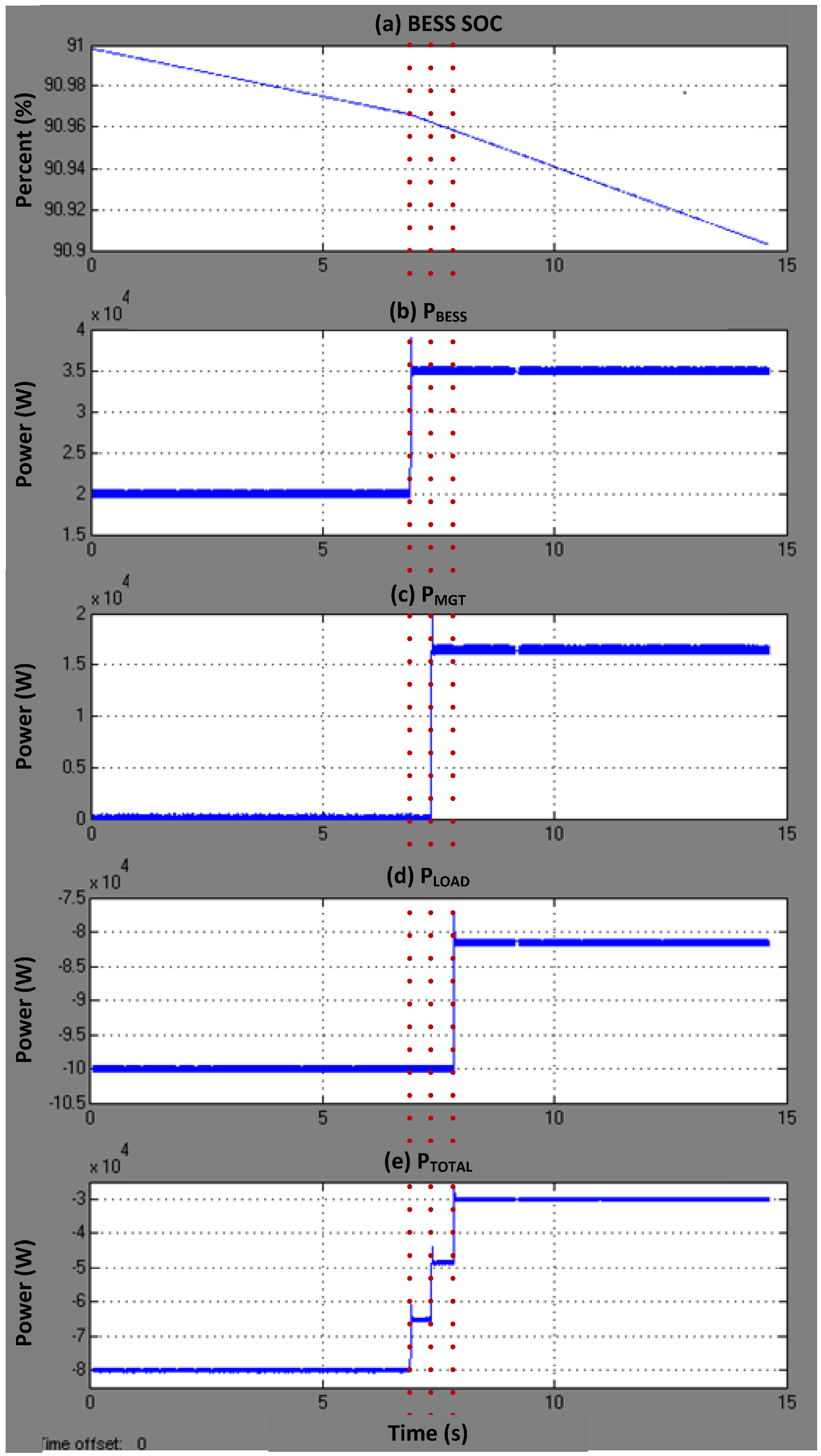
4.2. Experimental Results

HILS experiments are executed on the assumption that the LA requests an EDR event as 50 kW load reduction for 2 h (100 kWh). If there are not enough participation proposals from the agents, the MGCC can offer increased incentives to the agents over rounds. This means the incentive in the second round can be larger than that of the first round. In this way, the MGCC can choose cheaper solutions to match the EDR power. Here in the tests, we confine the CNP process up to two rounds at most for convenience for the experiments but if more CNP rounds are possible, the MGCC can reach more economical solution that is close to the optimal solution. Two cases are tested as follows.

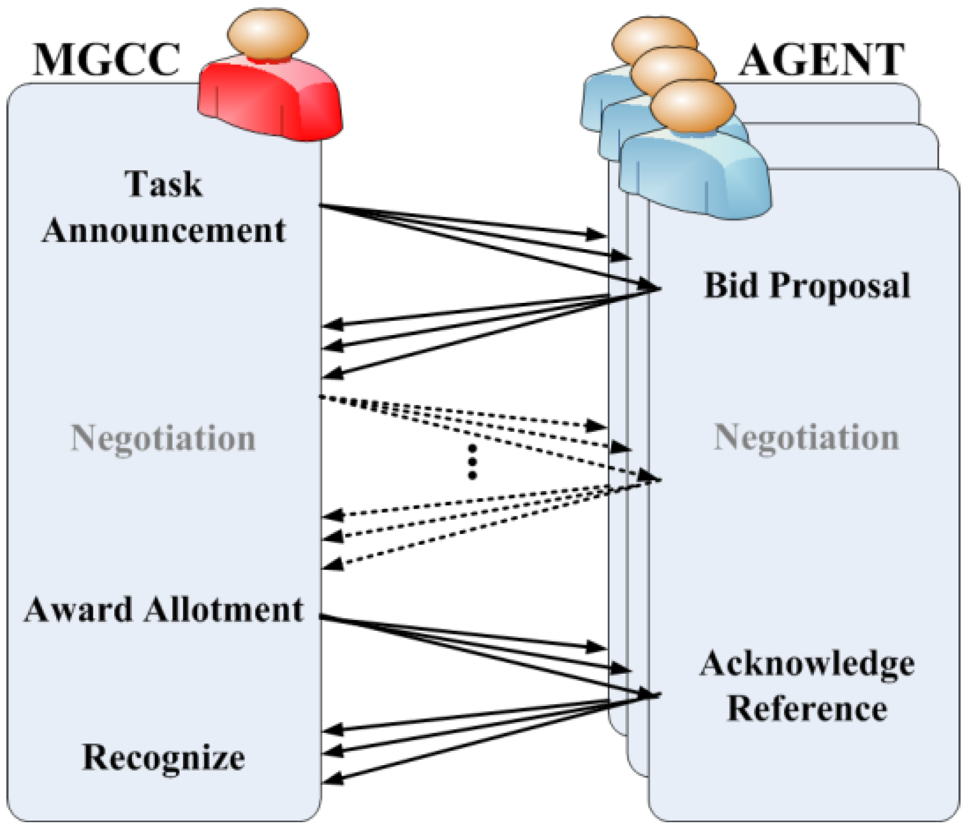
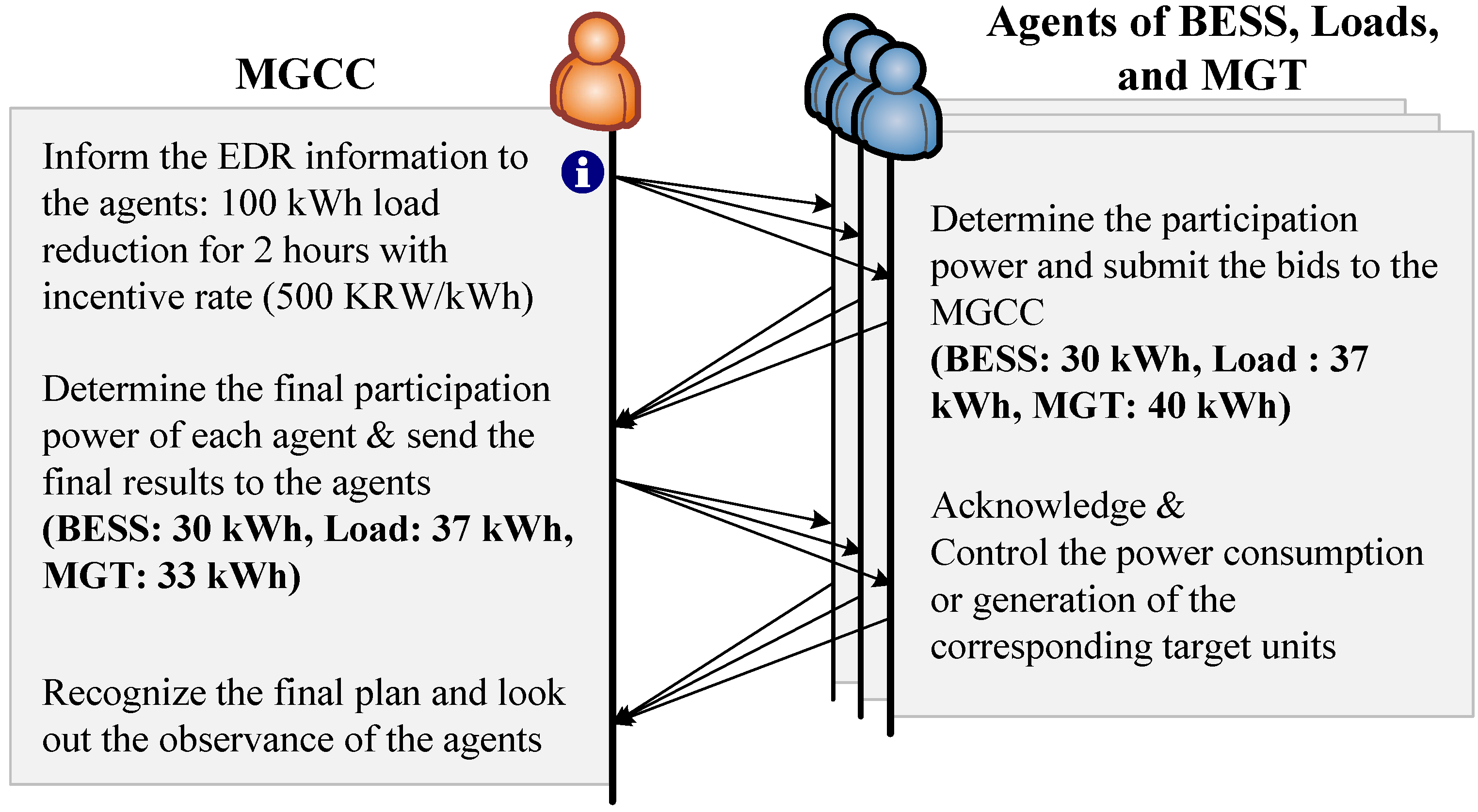
4.2.1. Case 1: One-Round CNP Procedure

As above mentioned, it is assumed that the LA requests for 100 kWh load-reduction for 2 h and the LA will pay 550 KRW/kWh as the performance incentive. There is a high possibility that the EDR events might occur during the peak loading conditions around between 13:00 to 17:00 During the peak hours, the BESS normally discharges the stored energy to the grid at 0.2 C-rate. Since the SOC of the BESS must be maintained between 20% and 100%, the BESS can discharge for up to 4 h when it is fully charged. The loads vary randomly around the average values. The experimental conditions for Case 1 are as follows:
  • The MGCC informs the EDR event and determines the first-round incentive as 500 KRW/kWh and the second-round incentive as 550 KRW/kWh;
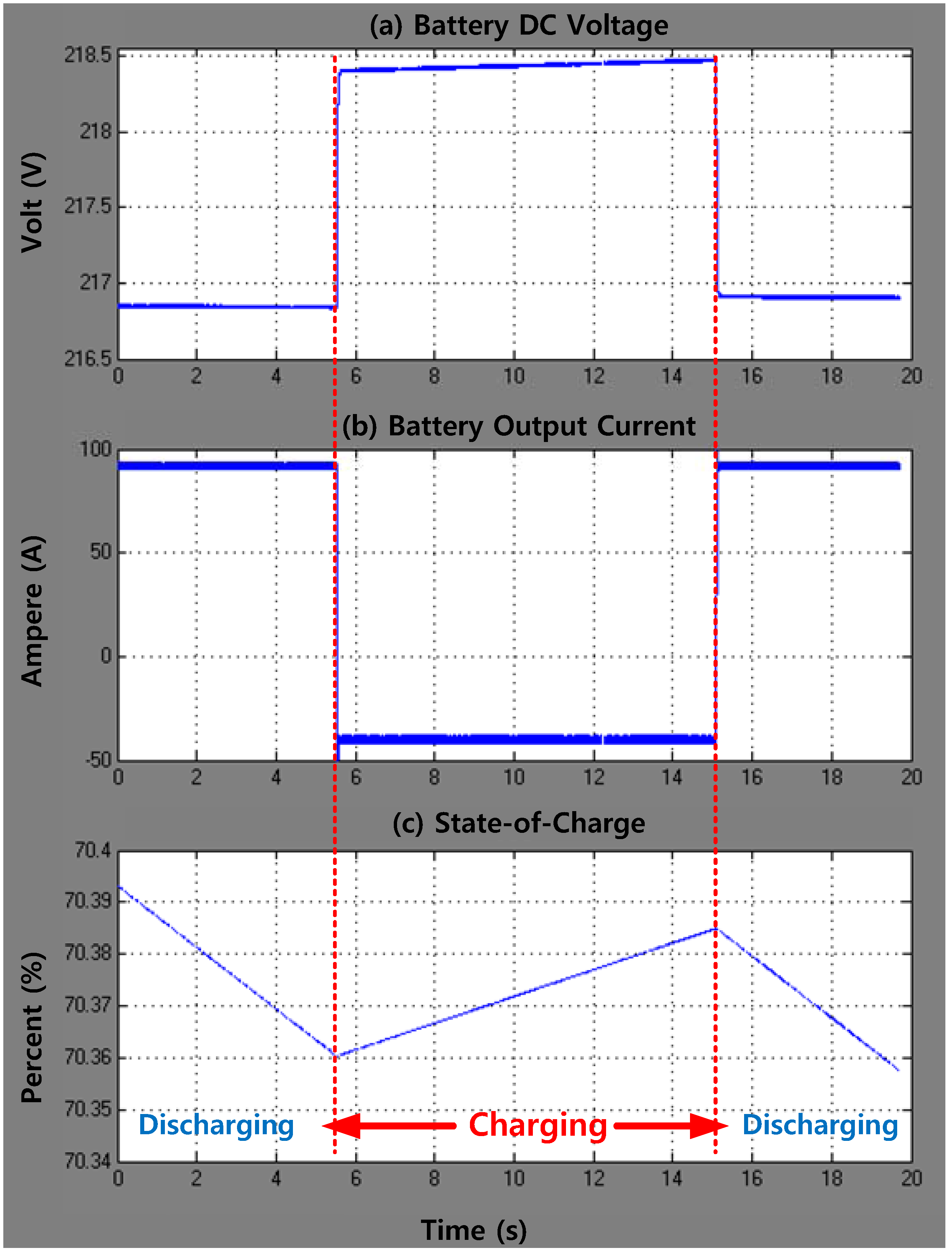
  • The EDR request arrives during the peak loading conditions. At that time, the BESS is discharging at 0.2 C-rate and the SOC is 90% at the moment;
  • The controllable, critical and sensitive loads are measured as 18.5 kW, 19.5 kW, and 62.0 kW, respectively, at the moment;
  • The MGC stands by keeping the generation capability up to 20 kW.
Because the SOC is 90% at the moment, the BESS can discharge at up to 0.35 C-rate for the next two hours as:
90 % 20 % 2   hours = 35   [ % / hr ] = 0.35   [ C-rate ]
This means that the BESS can participate in the EDR event as much as 0.15 C-rate per hour because the BESS was already discharging at 0.2 C-rate. Therefore, the BESS agent can propose 30 kWh for 2 h to the MGCC (i.e., 100   kW × 0.15   C r a t e × 2   h = 30   kWh ).
The load agent can propose 37 kWh instant load reduction for 2 h, which is the same as the amount of the controllable loads (18.5 kW × 2 h = 37 kWh). In addition, the MGT agent can propose 40 kWh backup generation for 2 h if needed by the MGCC. Then, the total sum of the first-round bids becomes 107 kWh for 2 h, which is larger than the EDR request power. Therefore, the MGCC determines the amount of participation powers of the agents for the next 2 h by following above-mentioned five priorities: 30 kWh for the BESS, 37 kWh for the loads, and the remaining 33 kWh for the MGT. Figure 13 illustrates the decision-making procedure between the MGCC and the agents using CNP in Case 1.
Figure 14 shows the HILS experimental results of Case 1. Figure 14a shows the SOC values of the BESS. It can be noted that the SOC is about 90% in the beginning and the discharging rate of the BESS increases. Figure 14b,c,d shows the power generation/consumption of the BESS, MGT and loads.
The BESS increases the discharging power from 20 kW to 35 kW to supply 30 kWh EDR power for 2 h and the MGT provides 16.5 kW to match 33 kWh EDR power for 2 h. Similarly, the load reduces the power consumption as much as 18.5 kW to follow 37 kWh load reduction for 2 h. Then, 50 kW in the total power consumption of the microgrid decreases as shown in Figure 14e. The noises in the graphs in Figure 14b through Figure 14e are caused by the PWM operation of the power converters of the BESS and the MGT. The time delays in the power control results from the ZigBee wireless communication delay between the MGCC and the agents.
Figure 13. Decision-making procedure based on CNP (Case 1).
Energies 06 03263 g013
Figure 14. HILS experimental results (Case 1). (a) Battery SOC; (b) BESS output power; (c) MGT output power; (d) Load consumption power; (e) Power at the PCC.
Energies 06 03263 g014

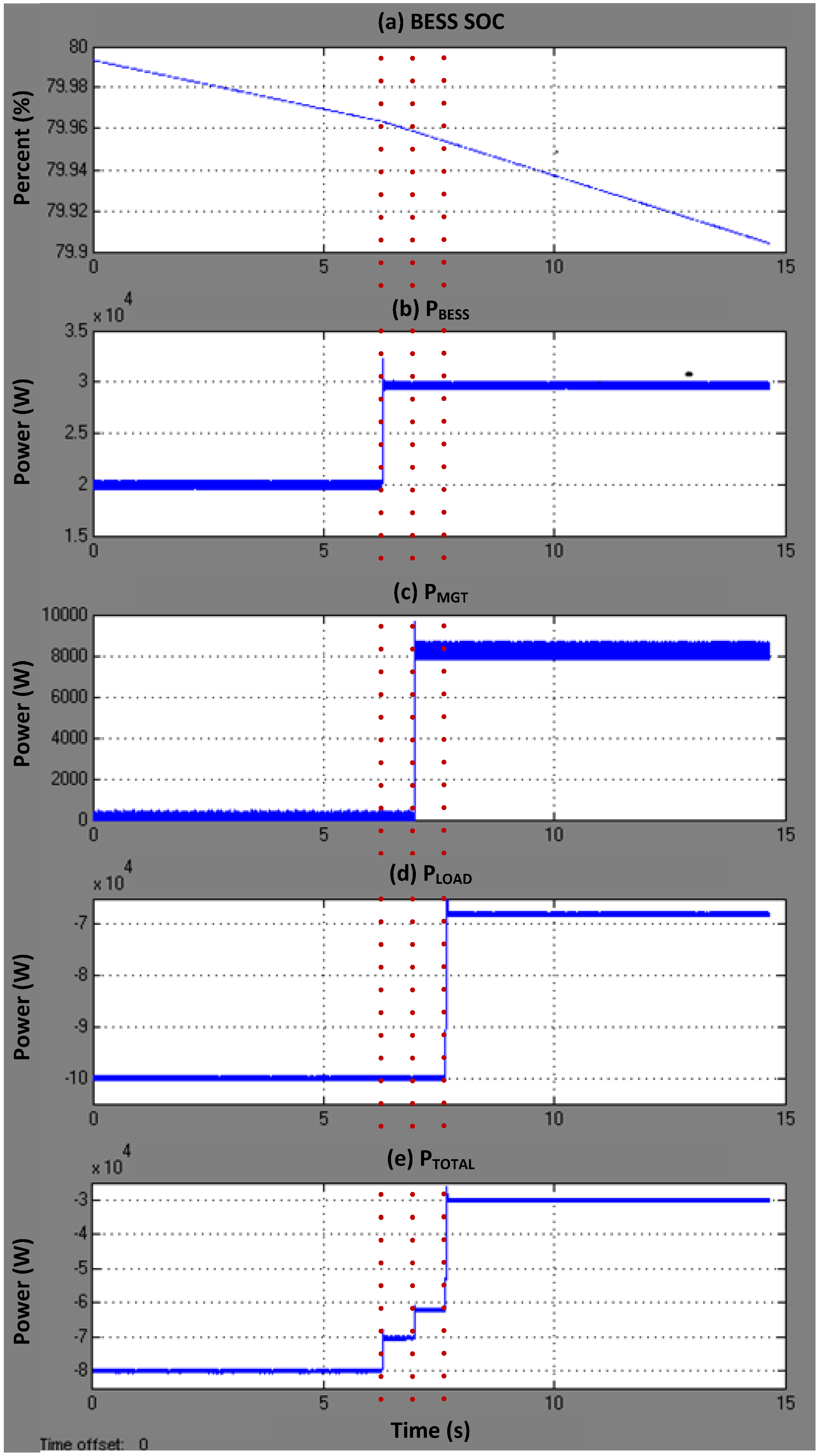
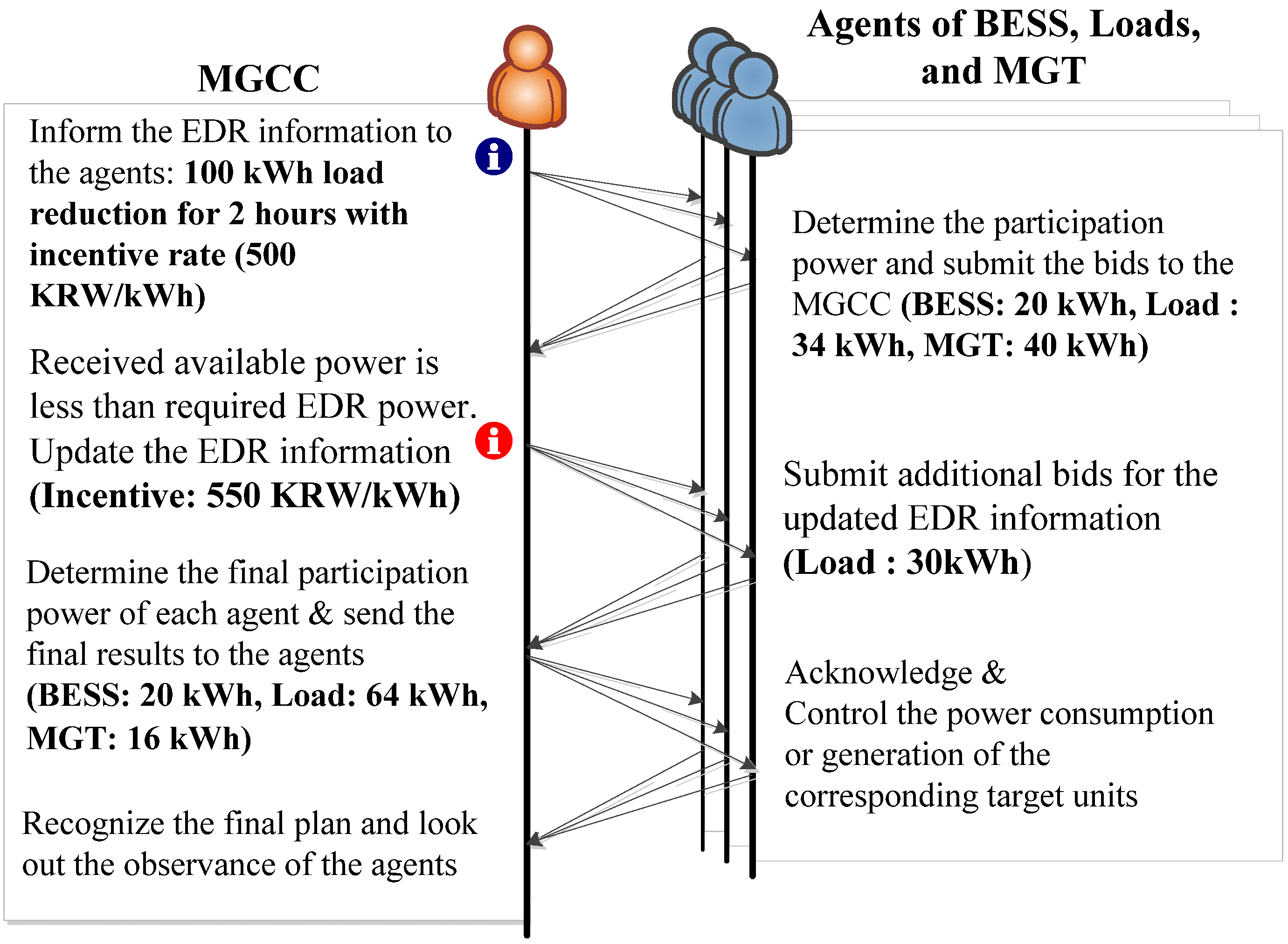
4.2.2. Case 2: Two-Round CNP Procedure

The experimental conditions of Case 2 are similar to Case 2. The difference is as follows:
  • The EDR event occurs at 14:00 or 1 hour after the peak hours. Therefore, the initial SOC of the BESS is 80% when the EDR request arrives;
  • The controllable, critical and sensitive loads are measured as 17.0 kW, 15.0 kW, and 68.0 kW, respectively, at the moment.
Then, the BESS can discharge at up to 0.30 C-rate for the next two hours as:
80 % 20 % 2   hours = 30   [ % / hr ] = 0.3   [ C-rate ]
Because the BESS was discharging at 0.2 C-rate before the EDR events, it means that the BESS can participate in the EDR event as much as 0.1 C-rate per hour. Therefore, the BESS agent can bid 20 kWh for 2 h. In the first round, the load agent can propose 34 kWh instant load reduction for 2 h, which is the same as the amount of the controllable loads. The MGT agent notifies 40 kWh backup generation for 2 h if needed. Then, the total sum of the first-round bids becomes 94 kWh for 2 h, which is smaller than the EDR request power, 100 kWh for 2 h.
Then, the MGCC updates the incentive from 500 KRW/kWh to 550 KRW/kWh and asks for the second round bids. Then, the load agents may be able to bid 30 kWh load reduction as much as the size of the critical loads. Now, at the end of the second round communication, the MGCC receives the bids as follows: 20 kWh from the BESS, 34 kWh for controllable loads, 30 kWh for critical loads, and 40 kWh from the MGT. The total sum of the EDR powers exceeds the EDR request, 100 kWh. Hence, the MGCC can determine the EDR power dispatching plan by following the above-mentioned five priorities. The final plan would be 20 kWh for the BESS, 64 kWh for the loads, and 16 kWh for the MGT for 2 h each. In practical cases, the detailed values of the incentives and the size of the microgrid entities may be modified to fit for the realities but we think the values we assumed in this case do not lose much generosity. Figure 15 illustrates the decision-making procedure of Case 2.
Figure 15. Decision-making procedure based on CNP (Case 2).
Energies 06 03263 g015
Figure 16 shows the HILS experimental results of Case 2. Figure 16a shows the SOC variation of the BESS. The SOC is around 80% and the discharging rate of the BESS increases when the BESS begins the EDR participation. Figure 16b,c,d shows the power generation/consumption of the BESS, MGT and loads. The BESS increases the discharging power from 20 kW to 30 kW to supply 20 kWh EDR power for 2 h and the MGT provides 8 kW to provide 16 kWh EDR power for 2 h. The load reduces the power consumption as much as 32 kW that is the sum of the controllable loads and the critical loads. Finally, as shown in Figure 16d the total power consumption of the microgrid decreases from 80 kW to 30 kW. This means 100 kWh load reduction for 2 h. As explained in Figure 14, the noises in the graphs in Figure 16 b–e are caused by the PWM operation of the power converters of the BESS and the MGT and the time delays occurs due to the ZigBee communication delay between the MGCC and the agents.
Figure 16. HILS experimental results (Case 2). (a) Battery SOC; (b) BESS output power; (c) MGT output power; (d) Load consumption power; (e) Power at the PCC.
Energies 06 03263 g016

5. Conclusions

This paper presents the development of HILS test-bed for the MAS-based microgrid distributed intelligent management system (DIMS). The developed DIMS consists of the MGCC and multiple agents for distributed control of a microgrid. This paper elaborates the details of the hardware development of the agents and also the software of the MGCC and the agents. The agents are programmed to flexibly communicate with the other agents and the MGCC via the CNP and then finally find a solution of target units. In this paper, intelligent decision-making scheme for emergency demand response program is proposed and tested on the developed HILS system.
In this paper, the decision-making algorithms of the agents specifically target Intelligent EDR program designed by Korea Power Exchange (KPX) for relatively small-scale loads whose rated powers are less than 3000 kW, as explained in Section 2.2. Because one of the design purposes of the KPX’s EDR program is to accomplish load reduction rapidly and securely, the EDR programs as well as the corresponding agent decision-making algorithms need to be relatively compact and simple. For future extension, the developed DIMS will be apply to Direct DR program that follows electricity markets so that more intelligent and smart algorithms based on artificial intelligence will be implemented in the intelligent agents.

Acknowledgments

This research was supported by the Ministry of Science, ICT and Future Planning, Korea, under the Information Technology Research Center support program (NIPA-2013-H0301-13-2007) supervised by the National IT Industry Promotion Agency and electricity delivery of the Korea Institute of Energy Technology Evaluation and Planning (KETEP) grant funded by the Korea government Ministry of Knowledge Economy (20111020400080).

Conflict of Interest

The authors declare no conflict of interest.

References

  1. Lasseter, R.H. Control and Design of Microgrid Components; PSERC Final Report; Power Systems Engineering Research Center: Ithaca, NY, USA, 2007. [Google Scholar]
  2. Hatziargyriou, N.; Asano, H.; Iravani, R.; Marnay, C. Microgrids. IEEE Power Energy Mag. 2007, 4, 78–94. [Google Scholar] [CrossRef]
  3. Saraiva, J.T.; Gomes, M.H. Provision of Some Ancillary Services by Microgrid Agents. In Proceedings of 7th International Conference on the European Energy Market, Madrid, Spain, 23–25 June 2010; pp. 1–8.
  4. Wooldridge, M. An Introduction to Multiagent Systems, 2nd ed.; John Wiley and Sons: Chichester, UK, 2009. [Google Scholar]
  5. Logenthiran, T.; Srinivasan, D.; Khambadkone, A.M. Multi-agent system for energy resource scheduling of integrated microgrids in a distributed system. Electr. Power Syst. Res. 2011, 81, 138–148. [Google Scholar] [CrossRef]
  6. Oyarzabal, J.; Jimeno, J.; Ruela, J.; Engler, A.; Hardt, C. Agent based Micro Grid Management System. In Proceedings of 2005 International Conference on Future Power Systems, Amsterdam, The Netherlands, 18 November 2005; p. 6.
  7. Lagorse, J.; Paire, D.; Miraoui, A. A multi-agent system for energy management of distributed power sources. Renew. Energy 2010, 35, 174–182. [Google Scholar] [CrossRef]
  8. Kim, H.; Kinoshita, T. A multiagent system for microgrid operation in the grid-connected mode. J. Electr. Eng. Tech. 2010, 5, 246–254. [Google Scholar] [CrossRef]
  9. Albadi, M.H.; El-Saadany, E.F. Demand Response in Electricity Markets: An Overview. In Proceedings of 2007 IEEE Power Engineering Society General Meeting, Tampa, FL, USA, 24–28 June 2007; pp. 1–5.
  10. Yoo, C.; Choi, W.; Chung, I.; Won, D.; Hong, S.; Jang, B. Hardware-in-the-Loop Simulation of DC Microgrid with Multi-Agent System for Emergency Demand Response. In Proceedings of IEEE Power and Energy Society General Meeting, San Diego, CA, USA, 22–27 July 2012; pp. 1–6.
  11. Dufour, C.; Abourida, S.; Belanger, J. Hardware-in-the-Loop Simulation of Power Drives with RT-LAB. In Proceedings of International Conference on Power Electronics and Drives Systems (PEDS 2005), Kuala Lumpur, Malaysia, 28 November–1 December 2005; pp. 1646–1651.
  12. Kim, J.; Nam, Y.; Hahn, T.; Hong, H. Demand Response Program Implementation Practices in Korea. In Proceedings of 18th International Federation of Automatic Control (IFAC) World Congress, Milano, Italy, 2 September 2011; pp. 3704–3707.
  13. Yoo, T.; Kwon, H.; Lee, H.; Rhee, C.; Yoon, Y.; Park, J. Development of Reliability Based Demand Response Program in Korea. In Proceedings of IEEE PES Innovative Smart Grid Technologies (ISGT), Anaheim, CA, USA, 17–19 January 2011; pp. 1–6.
  14. Aalami, H.; Yousefi, G.R.; Moghadam, M.P. Demand Response Model Considering EDRP and TOU Programs. In Proceedings of Transmission and Distribution Conference and Exposition, Chicago, IL, USA, 21–24 April 2008; pp. 1–6.
  15. Wu, J. Contract Net Protocol for Coordination in Multi-Agent System. In Proceedings of 2nd International Symposium on Intelligent Information Technology Application, Shanghai, China, 20–22 December 2008; pp. 1052–1058.
  16. Zheng, L. ZigBee Wireless Sensor Network in Industrial Applications. In Proceedings of SICE-ICASE (The Society of Instrument and Control Engineers—The Institute of Control, Automation and System Engineers) International Joint Conference, Busan, Korea, 18–21 October 2006; pp. 1067–1070.
  17. Liu, C.; Fan, C. Zigbee-Research into integrated Real-Time Location Systems. In Proceedings of 2008 IEEE Asia-Pacific Services Computing Conference, Yilan, Taiwan, 9–12 December 2008; pp. 942–947.
  18. Bai, Y.; Hung, C. Remote Power On/Off Control and Current Measurement for Home Electric Outlets based on a Low-Power Embedded Board and Zigbee Communication. In Proceedings of IEEE International Symposium on Consumer Electronics, Vilamoura, Portugal, 14–16 April 2008; pp. 1–4.
  19. Saito, H.; Kagami, O.; Umehira, M.; Kado, Y. Wide area ubiquitous network: The network operator’s view of a sensor network. IEEE Commun. Mag. 2008, 46, 112–120. [Google Scholar] [CrossRef]
  20. Ren, W.; Sloderbeck, M.; Steurer, M.; Dinavahi, V.; Noda, T.; Filizadeh, S.; Chevrefils, A.R.; Matar, M.; Iravani, R.; Dufour, C. Interfacing issues in real-time digital simulators. IEEE Trans. Power Deliv. 2011, 26, 1221–1230. [Google Scholar] [CrossRef]

