Application and Comparison of Different Combustion Models of High Pressure LOX/CH4 Jet Flames


Abstract
: The present work focuses on the numerical modeling of combustion in liquid-propellant rocket engines. Pressure and temperature are well above thermodynamic critical points of both the propellants and then the reactants show liquid-like characteristics of density and gas-like characteristics for diffusivity. The aim of the work is an efficient numerical description of the phenomena and RANS simulations were performed for this purpose. Hence, in the present work different kinetics, combustion models and thermodynamic approaches were used for combustion modeling first in a trans-critical environment, then in the sub-critical state. For phases treatment the pure Eulerian single phase approach was compared with the Lagrangian/Eulerian description. For modeling combustion, the Probability Density Function (PDF) equilibrium and flamelet approaches and the Eddy Dissipation approach, with two different chemical kinetic mechanisms (the Jones-Lindstedt and the Skeletal model), were used. Real Gas (Soave-Redlich-Kwong and Peng-Robinson) equations were applied. To estimate the suitability of different strategies in phenomenon description, a comparison with experimental data from the literature was performed, using the results for different operative conditions of the Mascotte test bench: trans-critical and subcritical condition for oxygen injection. The main result of this study is the individuation of the DPM approach of the most versatile methods to reproduce cryogenic combustion adapted for different operating conditions and producing good results.1. Introduction
To enhance the performance of liquid-propellant rocket engines, combustion occurs in a high-pressure combustion chamber. Here liquid oxygen is injected as a spray of droplets and fuel, hydrogen or methane, in gaseous form [1,2]. If pressure and temperature are above the thermodynamic critical points of one or both propellants, the combustion process is strongly influenced by the reactants' behavior. For example, in trans-critical conditions, cryogenic oxygen shows liquid-like characteristics for the density and gas-like characteristics for the diffusivity and the solubility also depends on the pressure. At subcritical chamber pressures, inertial and surface tension forces stimulate the formation of a heterogeneous spray of droplets and filaments. Near the critical point surface tension and enthalpy of vaporization are small, and the interface separating the liquid and gas phases disappears [3,4]. All these aspects produce some difficulties in the development of the most appropriate mathematical models for the numerical simulations. Numerical simulations, on the other hand, are strategic for combustion chamber and spray behavior optimization without the necessity to realize expensive prototypes to experimentally test the behavior of the new geometry. Moreover, very often, the numerical simulations help to recognize the main parameters of a phenomenon to better direct the field testing. Hence it is not possible to consider a chamber optimization without an adequate numerical description. This is the driving force of the present work.
Cryogenic combustion is a subject characterized by a widespread interest in the scientific literature. In the literature, numerous papers discuss fluid injection, mixing dynamics and behavior using, for example, cold tests to investigate the structure of the injected propellant. For example in [5] and [6] cold analysis of a high pressure cryogenic spray and the visualization of the spray mixing with the gaseous fuel in the chamber are shown.
Studies concerning the cryogenic combustion of liquid oxygen and gaseous hydrogen are reported in different works such as [7,8] whose authors largely studied sprays and injection problems in cryogenic rocket engines. In the cited work, injection is studied for different chamber pressures (in the range 0.1–7 MPa) and under sub-critical and trans-critical conditions; more recently, attention was given also to Methane/Liquid-Oxygen (LOx) combustion as in [9]. Some works refer to methane combustion in diffusive burners characterized by a too low or high environmental pressure [9,10] or in premixed burners [11].
Experimental investigations on turbulent combustion of H2/LOx and CH4/LOx, were carried out with the Mascotte cryogenic test bench [12] and the M3 burner [9]. Despite these studies, limited quantitative experimental data are available to validate numerical codes. Several numerical studies [13–22] used the experimental data from the Mascotte test bench for the comparisons. In particular the RCM01b and the Mascotte V04 test cases were largely used for the comparison with the numerical results.
The main problems in cryogenic combustion modeling are connected with the particular behavior of the liquid oxygen spray that presents intermediate characteristics between a turbulent gaseous jet and a liquid spray and then, both the aspects have to be taken into account in the interpretation of the behavior of the phenomena under investigation [2]. Hence both thermodynamic and kinetic models have to be applied to try to accurately reproduce the real phenomenon.
An important aspect in the numerical simulation of cryogenic spray combustion is the modeling of kinetic mechanisms. The real phenomenon involves a large number of species and reactions but the level of description of combustion chemistry has to be drastically reduced down to a few species and a few reactions to decrease the computational costs. Hence it is necessary to use the most favorable reduced mechanism. In [23] different chemical kinetic mechanisms used in methane-air diffusive flame studies were compared, proving the efficiency of the reduced Jones-Lindsted kinetics model when used in cryogenic combustion simulation.
Very important are also the mixing and the kinetics time scales that influence the use of one combustion model or another. If the chemical reaction characteristic time can be considered similar to the transport process one, the reaction rate is dominated by the eddy properties and so it is a function of the turbulent kinetic energy, k, and the dissipation rate, ε [24,25]. Under these conditions, the use of the Eddy Dissipation Concept Model (EDC model) is reported in the literature [25]. On the contrary, if the chemical characteristic time scale can be considered much smaller than the flow time scale, the Damkohler number is very high and the chemistry could be considered infinitely fast. The burnt gas conditions are similar to chemical equilibrium conditions. In this situation, the use of the non-premixed combustion Equilibrium Probability Density Function (PDF) approach [26] and the PDF flamelet one [13,15] are reported in the literature. Established that the different combustion models refer to different combustion applications, in cryogenic combustion it is very difficult to choose the most appropriate one. EDC models present the advantage of accurately predicting the intermediate species' contributions to reactions, but they require a kinetic model studied for cryogenic oxy-combustion. At the same time an equilibrium approach like PDF is less connected with a detailed description of the kinetics but the hypothesis of equilibrium should produce an underestimation of the phenomenal complexity. The PDF model [16–21], in fact, permits one to model the finite-rate chemistry effects in turbulent flames that are governed by the computationally expensive reacting Navier-Stokes equations. The PDF equation represents the time fraction that the fluid spends in each species, temperature and pressure state. Using this approach, chemistry can be modeled as in chemical equilibrium with the Equilibrium PDF model or near chemical equilibrium with the Steady Laminar Flamelet model.
The thermodynamic approach is another important issue in the numerical simulations and in the literature the pure Eulerian single phase [13,16,27,28] and hybrid Discrete Phase Model (DPM) Eulerian/Lagrangian [12,14,29] approaches are reported.
In real rocket engines that use methane as fuel and liquid oxygen as oxidant, the first is driven in the chamber as a gas phase, and the other is injected in liquid phase under cryogenic conditions. The chamber pressure and temperature exceed the critical values for both fuel and oxidizer causing a trans-critical change of the liquid oxygen jet during the vaporization.
Experimental tests [7] reveal that the injected propellant has a hybrid structure between a turbulent gaseous jet and a liquid spray. This makes it more difficult to numerically treat the real phenomenon and it is necessary to test different numerical strategies as in the present work.
The first used strategy is an Eulerian single-phase method in which methane and oxygen are treated as gases and the liquid phase is neglected. The other used approach is the Eulerian/Lagrangian DPM spray description. Using the Eulerian/Lagrangian approach it is possible to describe the liquid jet as a discrete phase in the continuous gaseous phase. This gives better coherence for the numerical description. The vaporization involves all the flow equations: heat and mass transport, phase change, inter phase coupling, radiation and chemical reactions [30].
For the gas phase description, in the literature different Equations of State that treat the reactant as real gases (RG EoS) may be found. The most used are the Soave-Redlick-Knong and the Peng-Robinson ones [13,16–18,29,31,32].
The work of Kim et al. [33] is very useful to better clarify the difference between the ideal gas and the real gas EoSs application. In the cited work, NIST data [34] are compared with different equations of state concluding that SRK EoS correctly predicts the density variation of LOx, PR EoS overestimates densities under temperature conditions lower than the pseudo-boiling point but the difference is small in the region of interest (high pressure and high temperature) and IG EoS does not reproduce the real data.
In the present work, trans-critical and sub-critical test cases of the RCM3-VO4 of ONERA were used to make a comparison between different approaches in the numerical modeling of cryogenic flames. Different combustion models, kinetic descriptions and thermodynamic properties are used to ensure that the modeling approach will be accurate but computationally cheap. RANS simulations were performed.
Particularly, regarding the chemical kinetic scheme, a modified Jones-Lindstedt mechanism [27,28,35] was used in comparison with the most complex Skeletal model derived from the Grimech 3.0 mechanism [36]. Different combustion approaches (Eddy Dissipation Concept Model, non-premixed combustion Equilibrium PDF, PDF flamelet) were used and compared.
Both Eulerian/Eulerian and hybrid Eulerian/Lagrangian methods were used for the thermodynamic approach. Regarding the gas EoS, in the Eulerian cases, the gas was modeled using the Soave-Redlich-Kwong (SRK) real gas equation, while the Peng-Robinson equation was used in the Eulerian/Lagrangian cases to treat the gaseous phase. The simulation of the effects of different distributions of the droplets at the inlet in the DPM cases has been carried out.
2. The Numerical Models for Kinetics Description
The most important aspect in the kinetic modeling is the number of intermediate species and reactions used to model the real combustion phenomena. The involvement of a large number of chemical species and reactions will need a very large computational time. Hence, it is important to find a reduced kinetics model able to reproduce the real phenomena but less expensive for the calculation.
The kinetic models used in the present work have been:
Jones-Lindstedt mechanism [27] (JL): it is a multi-step reaction scheme that originally was dedicated to the combustion of methane/air mixtures; in the present work it was utilized in the Frassoldati [28,35] version that involves nine species and six reactions and regards the combustion of methane with pure oxygen (see Table 1);
Detailed Skeletal mechanism from Grimec 3.0 [19–21] (SKEL): it is a reduction of the detailed Grimech 3.0 mechanism and it was adapted for oxy-combustion without taking into account nitrogen compounds.
3. Combustion Numerical Models
An important characteristic of the combustion models is its ability to reproduce efficiently the physics of the real phenomenon. The following numerical approaches for chemical kinetic modeling have been used:
Eddy Dissipation Concept Model (EDC) [25];
Chemical Equilibrium Probability Density Function (PDF) [37];
Probability Density Function flamelet combustion models (PDFfla) [26].
In the studied application the chemical reaction characteristic time can be considered similar to the transport process one as previewed by the Eddy Dissipation Concept (EDC) model. In turbulent flows, the reaction rate is dominated by the eddy properties and so it is a function of the turbulent kinetic energy, k, and the dissipation rate, ε.
The Finite Rate approach, associated with the EDC model, assumes the reaction rate [25] as controlled by the turbulence.
Details about the equations for this model may be found in previous works [16–21] and easily in literature.
Another useful approach in combustion description is the probability density function (PDF) model. Using models with species transport and finite-rate chemistry the species equations are Reynolds-averaged and some information about turbulent scalar flux and mean reaction rate are lost. The PDF model permits one to model the finite-rate chemistry effects in turbulent flames that are governed by the computationally expensive reacting Navier-Stokes equations. The probability density function (PDF) represents a general statistical description of the turbulent reacting flow. This PDF can be considered to be proportional to the fraction of time the fluid spends at each chemical species, temperature, and pressure state. From the PDF, any thermo-chemical moment such as the mean and RMS chemical species or temperature can be determined. The equations of the PDF model may be found in other works [16–21].
Using this approach, chemistry can be modeled as in chemical equilibrium with the Equilibrium PDF model or near chemical equilibrium with the Steady Laminar Flamelet model.
This second type of approach, in non-premixed combustion, could better describe the interaction chemistry/turbulence in the limit of fast reactions (large Damkohler number).
4. Gas and Liquid Phases Equations of State and Thermodynamic Properties
The first model regards a pure Eulerian single-phase method in which methane and oxygen are treated as gases and the liquid phase is neglected. For the DPM Eulerian/Lagrangian spray description, in the gas flow, another flow of discrete fluid droplets was introduced treating the first with an Eulerian description and the other with a Lagrangian approach. At the interface between the phases, the partial pressure of the vapor is considered equal to the saturated vapor pressure calculated at the liquid temperature. Hence, the concentration of the ith species vapor in the gas is obtained from the solution of the transport equation for the same species and the droplet's temperature takes into account also the heat exchange with the gaseous phase [37]. Using this approach the oxygen may be considered in its real liquid state and the vaporization of the liquid is implemented to define the gaseous mixing between reactants. The rate of vaporization is governed by the gradient diffusion, with the flux of droplet vapor into the gas phase related to the difference in vapor concentration at the droplet surface and the bulk gas.
4.1. Real Gas EoS
Attempting to better reproduce the real behavior of the spray, an EoS was used for both the reactants. The aim of a real gas equation of state is to reproduce the real density of the cryogenic jet even if it is treated as a gaseous phase. In literature a large number of equations of state for real gas have been presented and used. The Soave-Redlick-Kwong (SRK) real gas equations of state is used in the pure Eulerian description while the Peng-Robinson (PR) one is used in the Lagrangian/Eulerian description. Details of the application of these equations can be found in [16–18].
It is important to note that different real equations of state might produce different numerical results. In previous works [16–22] regarding the investigated case, it was found that the difference in the results due to different real equation of state are not appreciable. Real gas equation of state, in the present work, is associated with the EDC and the PDF combustion approaches.
5. Experimental Benchmarks, Computational Grid and Numerical Cases
The Test Case RCM-3 Mascotte Single Injector [38,39] was used with the aim to compare the numerical results with the experimental data. This test case was recently adapted to study the CH4/LOx combustion (version V04) [38,40].
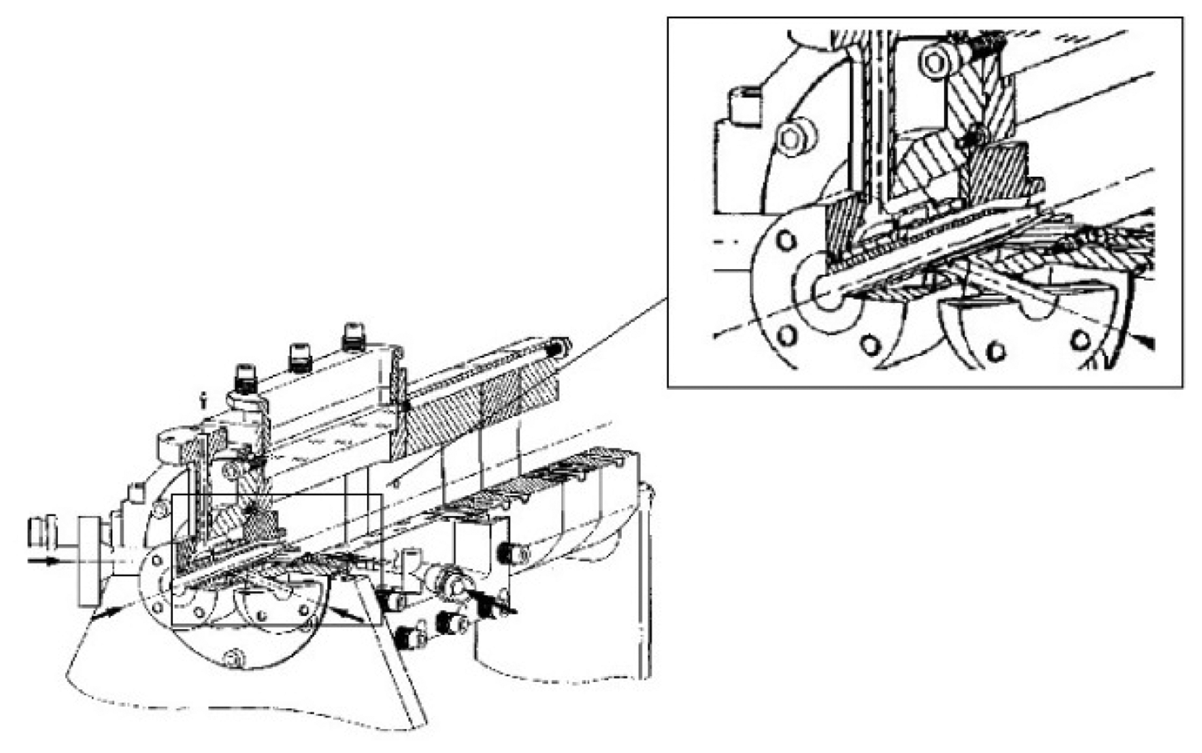
The injector has an inner diverging duct for the oxygen supply with inlet diameter equal to 0.005 m and outlet diameter equal to 0.0054 m. The methane is injected coaxially in an annular duct with outer diameter of 0.010 m and inner diameter of 0.0056 m. The injector is 0.0072 m long. The combustion chamber has a square section of 0.050 m × 0.050 m and the edge length is 0.050 m. In Figure 1 it is possible to see the entire chamber and a particular of the injector.
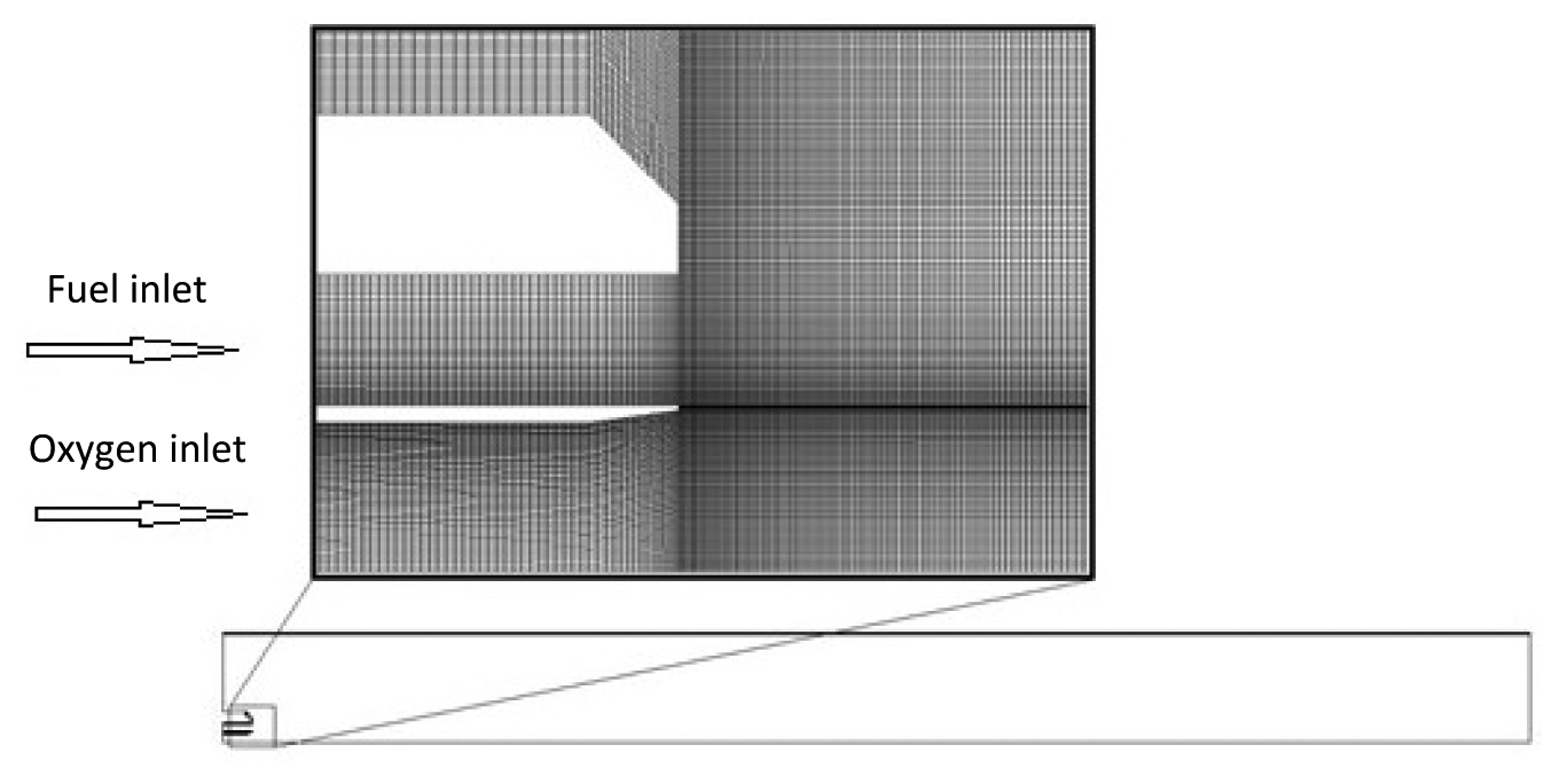
An axisymmetric simulation is performed, as in [38,39]. The combustion chamber is assumed as a cylinder with radius equal to 0.0282 m that preserves the chamber section area. The used computational grid is shown in Figure 2 and it consists of 123,660 rectangular cells. It was obtained using about 400 nodes in the axial direction and over 300 nodes in the radial direction for a region of about 0.320 m × 0.028 m [42]. Hence, the smallest cell is about 3.6 × 10⁻¹⁰ m2. The grid presents a higher number of divisions in the areas with high gradients of physical quantities of flow to ensure that the grid is fine enough to minimize the change of variables of the flow from cell to cell. Before choosing this grid as the most appropriate for the present simulations, different levels of refinement were applied to the geometry using the same strategy of differential thickening described before. In particular three grids were used.
The Richardson extrapolation method [43] was applied to the three grids and using as representative parameter the mean O2 concentration. The results of the analysis are reported in Table 3. For each grid the number of cells and the predicted mean value of O2 are indicated. Using the extrapolation method of Richardson the exact value for O2 and the grid convergence indexes were evaluated finding grid number 2 as the best compromise. It was chosen because it produces an error band of 0.21% and the number of cells is not so much high to make heavy the calculation.
The experimental conditions subcritical G1 and trans-critical G2 [39] were chosen as suitable references (see Table 4).The first part of the present work will regard the trans-critical G2 test case that was used for an intensive analysis of the different numerical strategies. The subcritical G1 test case, on the contrary, was used to test the efficiency of the best strategies to give good results in a different condition. The chamber pressure in the trans-critical G2 test case is set to 5.6 MPa. This value is higher than the critical pressure for both oxygen and methane that are 5.043 and 1.313 MPa, respectively. On the contrary, for the subcritical G1 test case, the pressure is set to 4.6 MPa. This value results a critical condition for the methane but it is subcritical for the oxygen.
Experimental dissertations were used for the comparison with the numerical results, in particular:
Average backlight images of the flame (Figure 3a) from [29] used for comparing the shape and the extension of the predicted flames, visualized through the temperature contours;
Instantaneous backlight images of the flame (Figure 3c) from [29] used for core length estimation.
OH images (Figure 3d) from [39] were used firstly for the definition of the experimental position of the flame end, reported in the predicted axial temperature profile; then it was also used for the direct comparison of the OH numerical contour.
In Table 5 the numerical cases analyzed in this work using different modeling approaches are summarized. In the following sections some comparisons around them will be shown taking into account their distinctive features. Results are divided into two main sections: firstly trans-critical G2 and then subcritical G1 test case simulations are shown.
The numerical simulations were carried out using the commercial CFD package Ansys Fluent® 14.5 (ANSYS, Inc., Canonsburg, PA, USA) [37].
To solve the fluid dynamic problem, a second order model was implemented. The modeling has been based on the general-purpose CFD code [37], which employs the finite volume method with a bounded central differencing scheme for discretizing the convection terms in the momentum transport equations.
A segregated pressure based solver has been used. Using the segregated solver, the conservation of mass and momentum were solved sequentially and a pressure-correction equation was used to ensure the conservation of momentum and the conservation of mass (continuity equation). The pressure-based solver employs an algorithm which belongs to a general class of methods called the projection method [40]. The pressure velocity coupling was obtained by the semi implicit method for pressure-linked equations SIMPLE algorithm. The SIMPLE algorithm updates the pressure and velocity fields from the solution of a pressure correction equation, solved by algebraic multi-grid (AMG) method.
6. Trans-Critical G2 Test Case Results
In this first section the numerical simulations of trans-critical G2 test case will be presented arranging the results in two sections regarding pure Eulerian single phase and Eulerian/Lagrangian cases.
6.1. Pure Eulerian Single Phase Approach
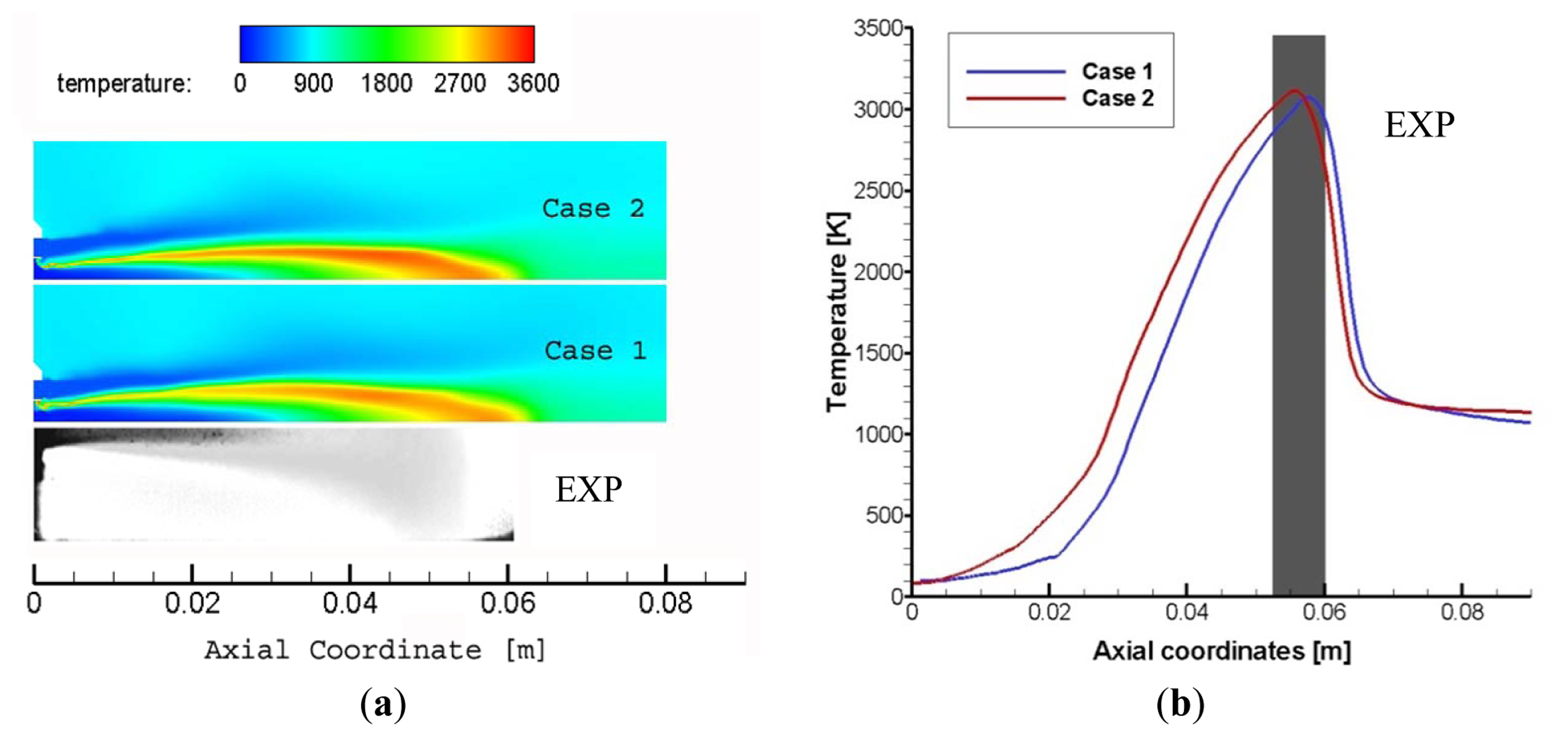
The first comparison of this section involves case 1 and case 2, with the focus on the kinetic scheme that was used. In fact, in case 1 the JL model and in case 2 the SKEL model were used. As said before, these two models are both reduced respect to the complete chemical kinetic system that involves hundreds of intermediate species. However the JL model consists of only six reactions while SKEL includes 41 reactions. It would appear that the SKEL model has to produce better results than JL but this last one is dedicated to oxy-combustion of methane, while the SKEL model is a general model for combustion of methane in air. As shown in Figure 4a, the two models actually produce very similar results. The flame shape is the same and the liquid core length appears also similar to experimental image. Looking to the peak temperature in Figure 4b it is evident that also the predicted temperature and the maximum position along the symmetry axis are quite close.
In the present work the comparison between the two kinetic mechanisms was made also for the other simulation strategies and this effect is evident also in the other cases. Hence the first conclusion of this work is that using a specific model based on oxy-combustion it is also possible to obtain a good result with a limited number of involved species. As regards the combustion strategy used in this comparison, an EDC model was applied and, as expected, the numerical results follow well the experimental data.
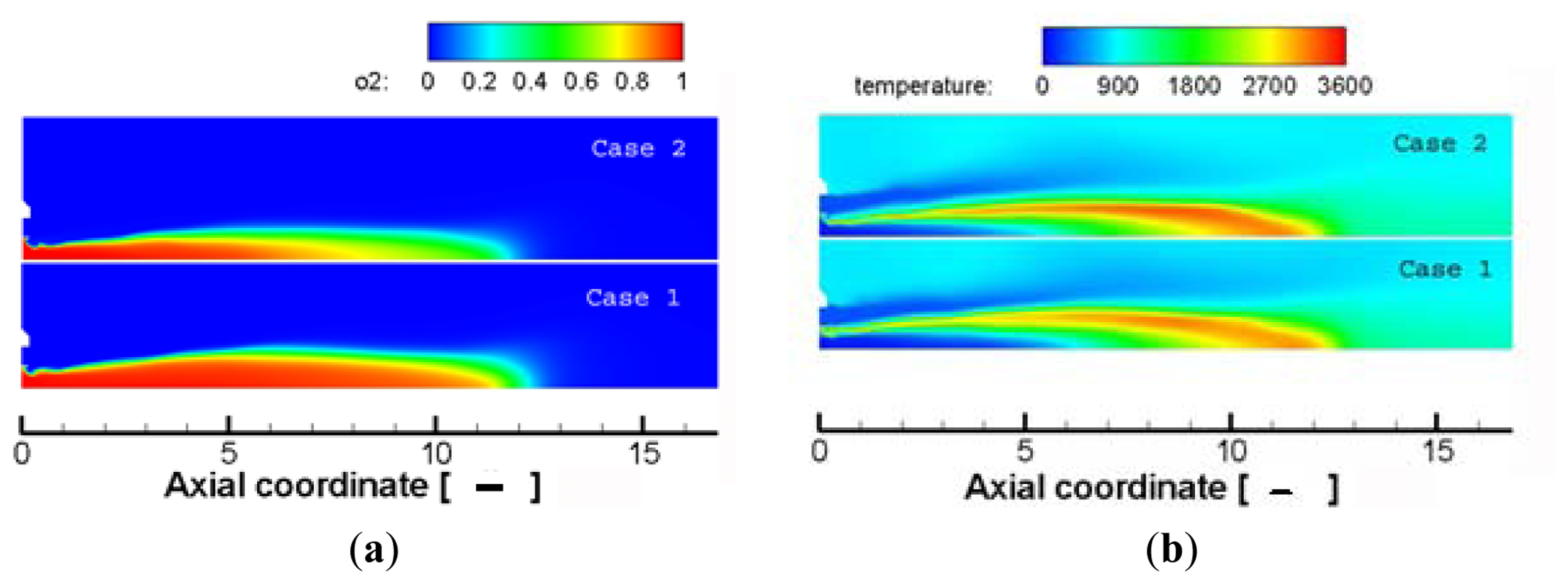
For the trans-critical G2 test case, in [39] it was reported that flame expands progressively starting from the injector exit up to seven times the oxygen injector diameter (dO2 in the following), where its blooming is less pronounced (angle of about 10 degrees); 7 dO2 is also the length of the liquid oxygen core; finally the flame is about 11 dO2. In Figure 5a there are the predicted O2 mass fraction contours of the numerical Cases 1 and 2 with adimensional abscissa (respect to dO2). Cases 1 and 2 exhibit a core length that is a little longer than the experimental data, especially case 1. In Figure 5b it is evident that also the flame length is overestimated with respect to the experimental one.
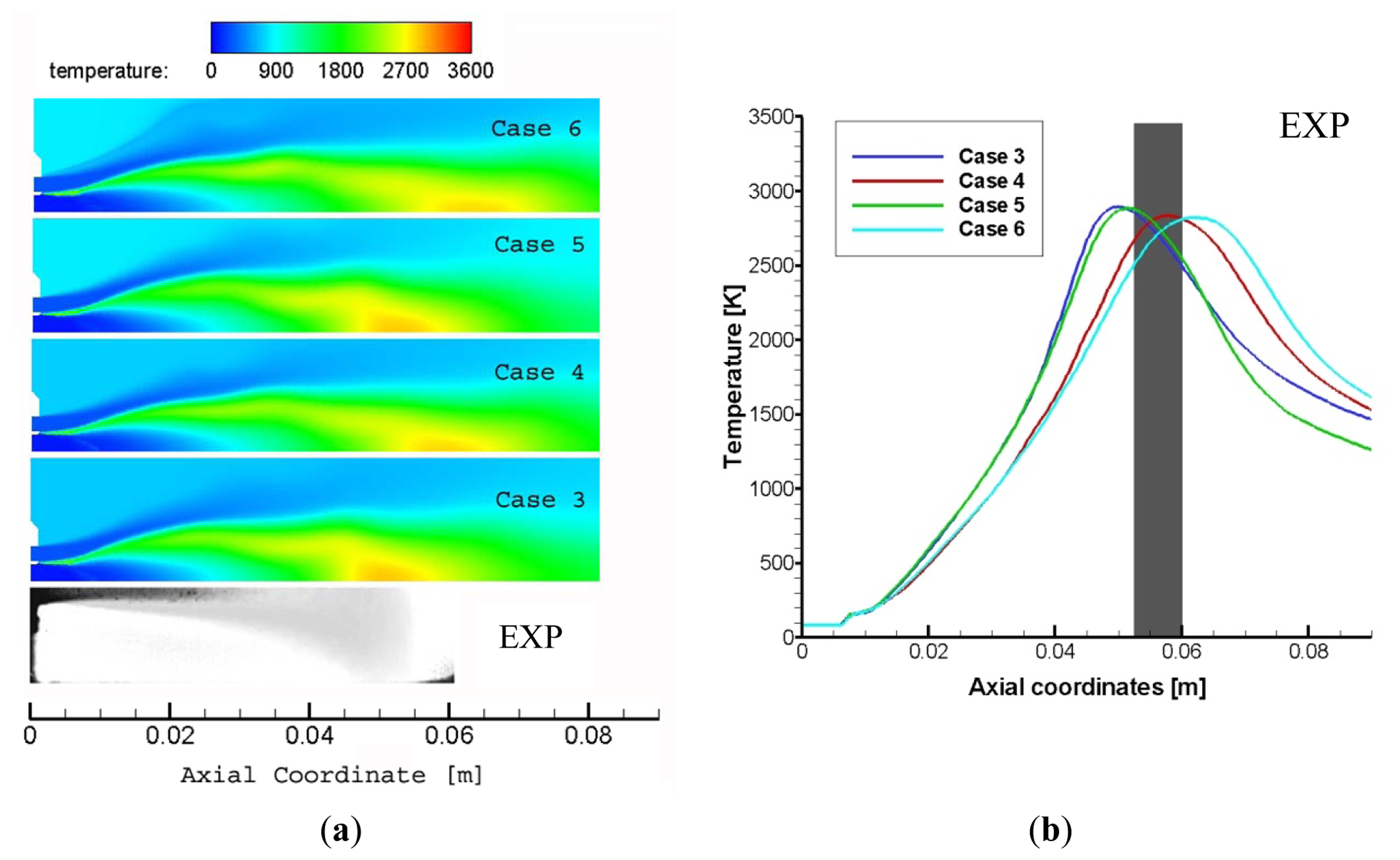
The second comparison of the present section concerns the predictions by the equilibrium PDF and PDF flamelet approaches (cases 3, 4, 5 and 6). As shown in Figure 6a predicted flame shapes are not so similar for both the approaches. The flame length and also the extension of the liquid core are not well predicted. The results differ from the data reported in [29]. In particular it is evident that using an equilibrium PDF approach in association with SKEL model, the temperature peak position is well estimated, but the flame shape is well above the real behavior of the flame. In conclusion PDF methods appear to not produce results as reliable as the cases with the EDC approach of the previous comparison. This effect is probably due to the intrinsic characteristics of the PDF methods: the intermediate species are taken into account through a mean parameter, that is the mixture fraction, evaluated in equilibrium conditions. Even introducing some non-equilibrium approach with the flamelet description, it is not possible to well estimate the real flame behavior that is distinctly not at equilibrium.
The most common approach for modeling injection in liquid fuel combustors is the Eulerian/Lagrangian one, in which the liquid phase is opportunely described as a discrete phase. In high pressure cryogenic combustion the spray does not appear as a liquid cloud of droplets but the vaporization is very fast, so a pure Eulerian single phase treatment could be applied. However, it is not completely satisfactory because in the real phenomenon, even with a quick vaporization, droplets of liquid are present and influence the flame behavior, so a comparison between the Eulerian single phase and the Eulerian/Lagrangian approach is necessary to individuate the best strategy to describe such a complex physical phenomenon.
6.2. Eulerian—Lagrangian Approach
The spray dynamics could be better reproduced by a DPM approach in association with a real gas treatment of the vapor phase. This numerical methodology involves the introduction of a certain number of droplets injected in the burner. Hence, to correctly simulate the spray it is important to define opportunely the injection conditions. In addition to liquid mass flow that obviously is the same of the pure Eulerian cases, it is necessary to define the droplets distribution, in particular two different droplet distributions were applied: the monodisperse and the Rosin-Rammler droplets distribution [37].
In the real atomization of the droplets, inertial and surface tension forces promote the formation of a heterogeneous spray of ligaments, pockets, and droplets, which evolves continuously [39]. The fast changes in spray structure makes difficult to define the main characteristic of the spray and different distributions have to be tested.
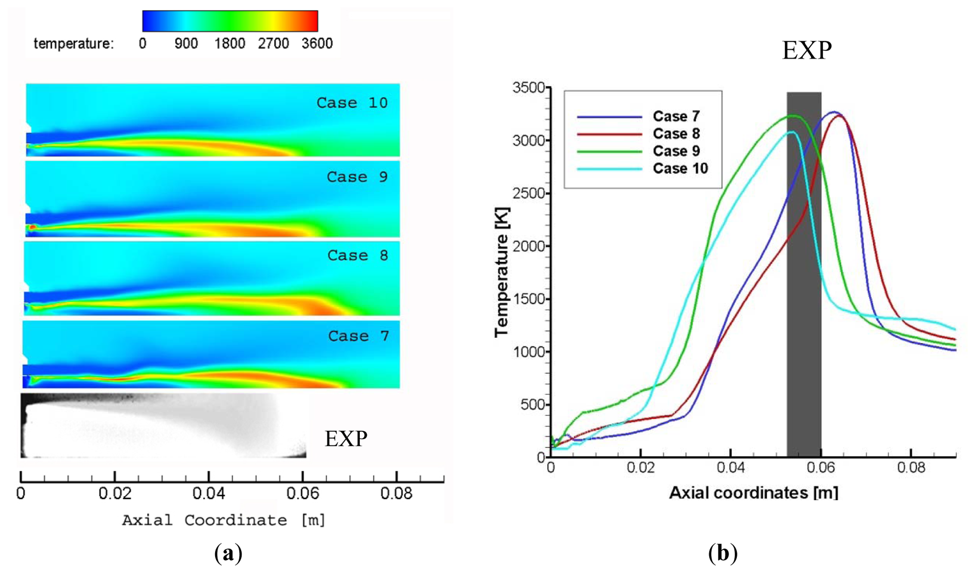
The monodisperse distribution of droplets is defined using a characteristic diameter d0 equal to 50 μm. The Rosin Rammler distribution has a mean diameter of the same value (50 μm) and the spread was set to 3.5; the range of variation in the droplet diameter was fixed at 0–200 μm. Total oxygen mass flow is the same for both distributions. The injection angle is set to about 8° that corresponds to the divergence angle of the injection ducts. Cases 7 and 8 involve a monodisperse injection of liquid oxygen while cases 9 and 10 a Rosin-Rammler one.
Figure 7 shows the comparisons between predicted axial temperature for these cases, to investigate the influence of the droplets distribution in the numerical description of the phenomenon. The vapor phase was treated using a real gas Peng-Robinson EoS. In Figure 7 both the temperature contours and the temperature axial profiles are in good agreement with the experimental data in all four cases. The predicted temperature peak position depends on the applied injection strategy. Using a monodisperse distribution the peak temperature value is farther away than in the Rosin Rammler case. The monodisperse droplets distribution leds to a longer flame and core than in the Rosin-Rammler application. The flame length is anyway well predicted.
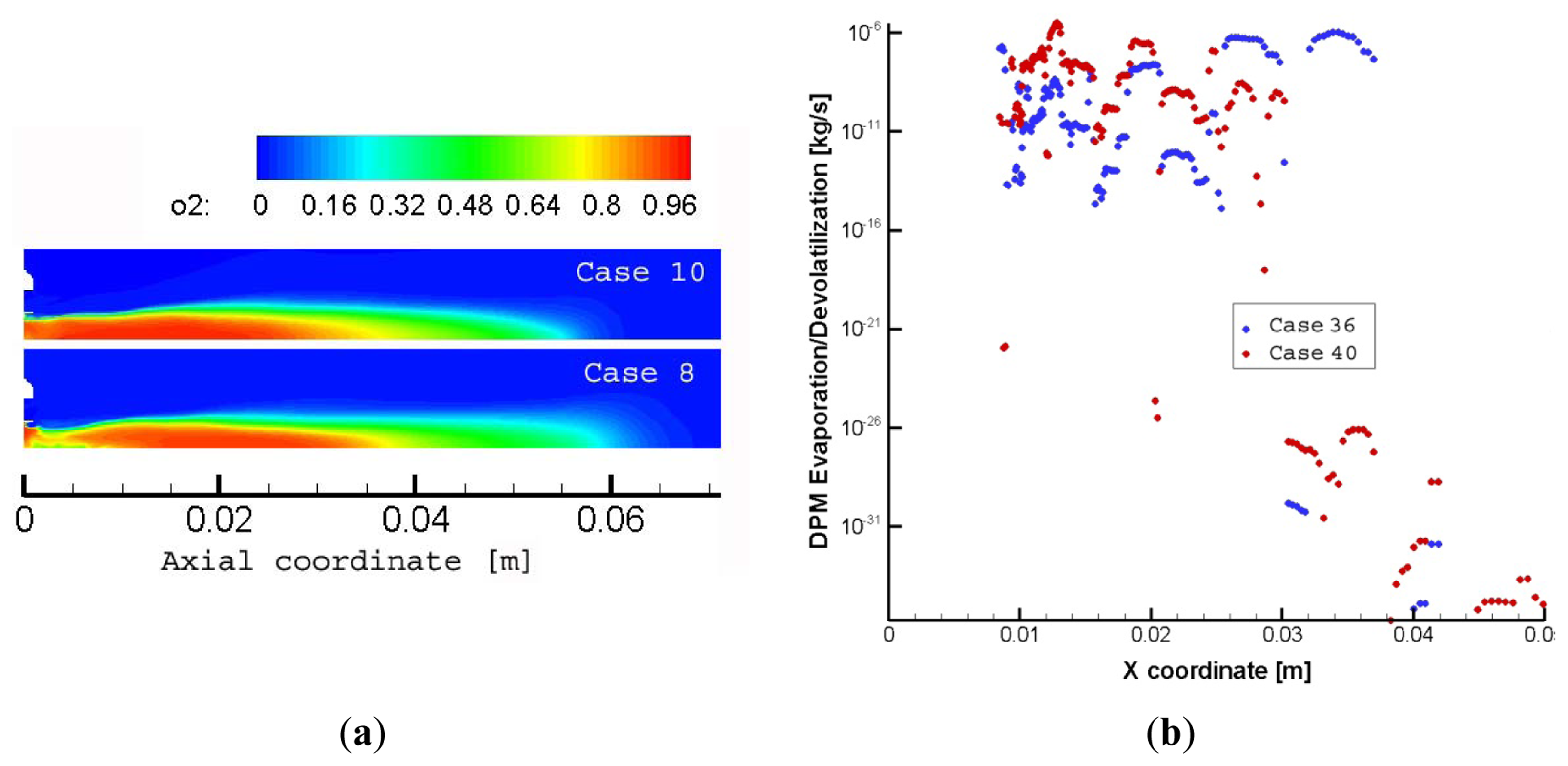
When droplets enter the combustion chamber, they are affected by two different forces: aerodynamic forces caused by the relative velocity between liquid and the surrounding gas, and hydrodynamic forces caused by the turbulence or other disruptive forces within the liquid itself. Aerodynamic forces develop waves on the liquid surface and consequently produce unstable ligaments that eventually disintegrate into droplets on any increase in the relative velocity [44]. As said the aerodynamic forces depend on the velocity and this last depends on the droplets diameter. Hence the presence of different diameter droplets produces a complex spatial distribution of aerodynamic forces that favorites the mixing and vaporization of droplets respect to a monodisperse spray. In fact, the comparison in Figure 7 permits us to make some considerations about the effectiveness of the used droplets distribution strategies. To underline the effect of the vaporization of the smaller droplets, in Figure 8a the oxygen field contour is depicted while in Figure 8b the vaporization rate axial profile of the cases 36 and 40 are shown. The vaporization of the liquid oxygen makes available the gaseous O2. Using a monodisperse droplets distribution, oxygen vaporization begins far away the injector. Using a Rosin-Rammler distribution the presence of small droplets produces an early vaporization, closer to the injector hole, and the evaporation rate is evidently higher in the first region. Hence the gaseous oxygen is available in advance and the temperature distribution is more homogeneous.
In conclusion, it looks like that the Rosin-Rammler droplets distribution should be used for better reproduction of experimental data.
With the aim to compare directly the pure Eulerian approach with the Eulerian-Lagrangian one, in Figure 9 we present the comparison between the pure Eulerian single phase case with Eddy Dissipation Concept Model, and the Eulerian-Lagrangian cases with monodisperse injection, and Rosin-Rammler injection. All these cases involve the SKEL Reaction Mechanism. In this comparison it becomes evident that results of the pure Eulerian approach are quite similar to the ones of the Eulerian-Lagrangian cases with Rosin-Rammler droplets distribution (case 10), both in terms of liquid core length and of flame length. The main difference between case 2 and case 10 regards the thickness of the flame region that, in this last case, appears more similar to experiment.
7. Subcritical G1 Test Case Results
As said before, in this second section the results of the subcritical G1 test case will be shown. For this test case only an Eulerian-Lagrangian approach is applied. The Eulerian single phase approach is not taken into account because in the subcritical injection condition the spray behavior is significantly different from the gas characteristics.
The results for cases 11, 12, 13 and 14 of Table 5 are shown in Figure 10 where there is the comparison between temperature contours, applying different droplet distributions and kinetics schemes.
As in the trans-critical G2 test case, also in the subcritical G1 test case the Eulerian-Lagrangian approach, associated with a real gas description of the gaseous species, produces a good agreement between the numerical results and the experimental ones. Moreover between the monodisperse and the Rosin-Rammler descriptions it is evident that the last one correctly estimates both core and flame lengths.
Yet again the Eulerian-Lagrangian approach with a Rosin-Rammler droplets distribution results the best strategy for numerical description of cryogenic combustion. Moreover it presents the advantage that it can be used both for transcritical and subcritical conditions, giving a good result.
8. Conclusions
In the present work some numerical simulations on the combustion phenomenon in liquid-propellant rocket engines were carried-out. Liquid oxygen and gaseous methane are driven in the combustion chamber separately and under different conditions: methane is in a gaseous state while oxygen is in a trans-critical (G2 test case) or subcritical (G1 test case) condition. The aim of the work was the comparison between commonly used approaches for the simulation of cryogenic combustion, to analyze the suitability of the different numerical models, hence different kinetic schemes, combustion models and thermodynamic approaches were used to simulate the combustion behavior in trans-critical conditions and subcritical state. Comparisons with experimental data from the literature were performed using the results for the G1 and G2 operative conditions of the Mascotte test bench.
An important aspect in the modeling of cryogenic spray combustion is the choice of the kinetic mechanisms. Results show that using the reduced Jones-Lindstedt (JL) kinetic mechanism or the more detailed Skeletal mechanism (SKEL), it is possible to predict in the same manner the main characteristics of the flame: axial position of the temperature peak, flame shape and liquid core length. Obviously a reduced model is less expensive in term of computational costs. Hence the JL model results as preferable in numerical simulation of cryogenic flames.
Independently of the kinetic model, the EDC approach produces good results. The temperature is well predicted as is the flame length; the liquid core length is similar despite not being perfectly equal to the experimental image. This was largely expected because the EDC approach is the most widely used method for combustion description. Unfortunately it is also very computationally expensive because the kinetic details are taken into account.
Less expensive than the EDC approach are the equilibrium PDF and the PDF flamelet. Using these approaches, the position of the temperature peak is not estimated so well and the flame shape is well above the real behavior of the flame; PDF methods appear not producing results so reliable as the cases with the EDC approach.
In the present work, besides the Eulerian single phase description, also a DPM Eulerian-Lagrangian hybrid approach was used.
The results of this second simulation strategy revealed that an Eulerian-Lagrangian approach allows one to model both the gaseous and liquid phases and to obtain a good reproduction of the flame, especially using a Rosim-Rammler distribution of the droplets for the injection modeling. In addition, it is important to note that the trans-critical G2 test case may be efficiently described both using an Eulerian single phase approach or an Eulerian-Lagrangian strategy. On the contrary, for the subcritical G1 test case the Eulerian single phase approach is not applicable.
Hence, the Eulerian-Lagrangian strategy produces satisfactory results in reproducing the experimental results in rocket combustion modeling. Moreover it results the only one that can be used under all the conditions: spray and combustion are well predicted both in trans-critical and subcritical conditions. In numerical analysis it is important to have a computational method that can be applied every time avoiding long and expensive preprocessing studies.
Conflicts of Interest
The authors declare no conflict of interest.
References
- Oefelein, J.C. Mixing and combustion of cryogenic oxygen-hydrogen shear-coaxial jet flames at supercritical pressure. Combust. Sci. Technol. 2006, 178, 229–252. [Google Scholar]
- Chehroudi, B.; Talley, D.; Coy, E. Visual characteristics and initial growth rates of round cryogenic jets at subcritical and supercritical pressures. Phys. Fluids 2002, 14, 850–861. [Google Scholar]
- Oschwald, M.; Schik, A. Supercritical nitrogen free jet investigated by spontaneous Raman scattering. Exp. Fluids 1999, 27, 497–506. [Google Scholar]
- Chehroudi, B.; Cohn, R.; Talley, D.; Badakhshan, A. Cryogenic shear layers: Experiments and phenomenological modeling of the initial growth rate under subcritical and supercritical conditions. Int. J. Heat Fluid Flow 2002, 23, 554–563. [Google Scholar]
- Mayer, W.; Telaar, R.; Branam, J.; Hussong, J. Raman measurements of cryogenic injection at supercritical pressure. Heat Mass Transf. 2003, 39, 709–719. [Google Scholar]
- Oschwald, M.; Smith, J.; Branam, R.; Hussong, J.; Schik, A.; Chehroudi, B.; Talley, D. Injection of supercritical fluids into supercritical environment. Combust. Sci. Technol. 2006, 178, 49–100. [Google Scholar]
- Mayer, W.; Tamura, H. Propellant injection in a liquid oxygen/gaseous hydrogen rocket engine. J. Propuls. Power 1996, 12, 1137–1147. [Google Scholar]
- Smith, J.; Klimenko, D.; Clauss, W.; Mayer, W. Supercritical LOX/Hydrogen Rocket Combustion Investigations Using Optical Diagnostics. Proceedings of the 38th AIAA/ASME/SAE/ASEE Joint Propulsion Conference and Exhibit, Indianapolis, IN, USA, 7–10 July 2002.
- Yang, B.; Cuoco, F.; Oschwald, M. Atomization and flames in LOX/H2 and LOX/CH4 spray combustion. J. Propuls. Power 2007, 23, 763–771. [Google Scholar]
- Zong, N.; Yang, V. Near-field flow and flame dynamics of LOX/methane shear-coaxial injector under supercritical conditions. Proc. Combust. Inst. 2007, 31, 2309–2317. [Google Scholar]
- Bibrzycki, J.; Poinsot, T.; Zajdel, A. Investigation of Laminar flame speed of CH4/N2/O2 and CH4/CO2/O2 mixtures using reduced chemical kinetic mechanisms. Arch. Combust. 2010, 30, 287–296. [Google Scholar]
- Zurbach, S.; Thomas, J.L.; Vuillermoz, P.; Vingert, L.; Habiballah, M. Recent Advances on LOX/Methane Combustion for Liquid Rocket Engine Injector. Proceedings of the 38th AIAA/ASME/SAE/ASEE Joint Propulsion Conference & Exhibit, Indianapolis, Indiana, 7–10 July 2002.
- Cutrone, L.; Ihme, M.; Herrmann, M. Modeling of High-Pressure Mixing and Combustion in Liquid Rocket Injectors. Proceedings of the 2006 Summer Program, Standford, CA, USA, December 2006; Available online: http://ctr.stanford.edu/ctrsp06/cutrone.pdf (accessed on 20 January 2014).
- Cutrone, L.; De Palma, P.; Pascazio, G.; Napolitano, M. A RANS flamelet-progress-variable method for computing reacting flows of real-gas mixtures. Comput. Fluids 2010, 39, 485–498. [Google Scholar]
- Minotti, A.; Sciubba, E. LES of a meso combustion chamber with a detailed chemistry model: Comparison between the flamelet and EDC models. Energies 2010, 3, 1943–1959. [Google Scholar]
- De Giorgi, M.G.; Tarantino, L.; Ficarella, A.; Laforgia, D. Numerical Modelling of High-Pressure Cryogenic Sprays. Proceedings of the 40th AIAA Fluid Dynamics Conference and Exhibit, Chicago, IL, USA, 28 June–1 July 2010.
- Ficarella, A.; de Giorgi, M.G. Fluid Modelling of Supercritical Reacting Flows in Liquid Rocket Engine. Proceedings of the 3rd European Conference for Aero-Space Sciences (EUCASS), Versailles, France, 6–9 June 2009.
- De Giorgi, M.G.; Leuzzi, A. CFD Simulation of Mixing and Combustion in LOX/CH4 Spray under Supercritical Conditions. Proceedings of the AIAA 39th Fluid Dynamics Conference and Exhibit, San Antonio, TX, USA, 22–25 June 2009.
- De Giorgi, M.G.; Sciolti, A.; Ficarella, A. Different Combustion Models Applied to High Pressure LOX/CH4 Jet Flames. Proceedings of the 4th European Conference for Aerospace Sciences Saint Petersburg, Russia, 4–8 July 2011.
- De Giorgi, M.G.; Sciolti, A.; Ficarella, A. Comparisons between Different Combustion Models for High Pressure LOX/CH4 Jet Flames. Proceedings of the 41st AIAA Fluid Dynamics Conference and Exhibit, Honolulu, HI, USA, 27–30 June 2011.
- De Giorgi, M.G.; Sciolti, A.; Ficarella, A. Spray and Combustion Modeling in High Pressure Cryogenic Jet Flames. Proceedings of the Turbine Technical conference and Exposition (ASME Turbo Expo 2012), Copenhagen, Denmark, 11–15 June 2012; pp. 1161–1176.
- Naccarato, F.; Potenza, M.; de Risi, A. Simultaneous LII and TC optical correction of a low-sooting LPG diffusion flame. Measurement 2014, 47, 989–1000. [Google Scholar]
- Lilleberg, B.; Panjwani, B.; Ertesvg, I.S. Large Eddy simulation of methane diffusion flame: Comparison of chemical kinetics mechanisms. AIP Conf. Proc. 2010, 1281, 2158–2161. [Google Scholar]
- Fru, G.; Thevenin, D.; Janiga, G. Impact of turbulence intensity and equivalence ratio on the burning rate of premixed methane–Air flames. Energies 2011, 4, 878–893. [Google Scholar]
- Magnussen, B.F. The Eddy Dissipation Concept. Proceedings of the Thematic Conference on Computational Combustion (ECCOMAS), Cracow, Poland, 30 June–2 July 2005.
- Haworth, D.C. A Probability Density Function/Flamelet Method for Partially Premixed Turbulent Combustion. Proceedings of the 2000 Summer Program, Stanford, CA, USA, 2–27 July 2000.
- Andersen, J.; Rasmussen, C.L.; Giselsson, T.; Glarborg, P. Global combustion mechanisms for use in CFD modeling under oxy-fuel conditions. Energy Fuels 2009, 23, 1379–1389. [Google Scholar]
- Frassoldati, A.; Cuoci, A.; Faravelli, T.; Ranzi, E.; Candusso, C.; Tolazzi, D. Simplified Kinetic Schemes for Oxy-Fuel Combustion. Proceedings of the 1st International Conference on Sustainable Fossil Fuels for Future Energy, Rome, Italy, 6–10 July 2009.
- Singla, G.; Scouflaire, P.; Rolon, C.C.S.; Zurbach, S.; Thomas, J. Experiments and Simulations of LOx/CH4 Combustion at High Pressures. Proc. Combust. Inst. 2005, 30, 2921–2928. [Google Scholar]
- Yan, C.; Aggarwal, S.K. A high-pressure droplet model for spray simulations. Trans. ASME 2006, 128, 482–492. [Google Scholar]
- Ierardo, N.; Congiunti, A.; Bruno, C. Mixing and Combustion in Supercritical O2/CH4Liquid Rocket Injectors. Proceedings of the 42nd AIAA Aerospace Sciences Meeting and Exhibit Reno, NV, USA, 5–8 January 2004.
- Minotti, A.; Bruno, C. Comparisons between simulations of real and ideal LRE combustion of LO2/CH4. Recent Pat. Space Technol. 2010, 2, 1–9. [Google Scholar]
- Kim, S.K.; Choi, H.S.; Kim, Y. Thermodynamic modeling based on a generalized cubic equation of state for kerosene/LOx rocket combustion. Combust. Flame 2012, 159, 1351–1365. [Google Scholar]
- National Institute of Standards and Technology (NIST). Available online: http://webbook.nist.gov/chemistry/fluid/ (accessed on 20 January 2014).
- Cuoci, A.; Frassoldati, A.; Faravelli, A.; Ranzi, E. Accuracy and flexibility of simplified kinetic models for CFD applications. Combust. Colloq. 2009, II-6, 1–6. [Google Scholar]
- Smith, G.P.; Golden, D.M.; Frenklach, M.; Moriarty, N.W.; Eiteneer, B.; Goldenberg, M.; Bowman, C.T.; Hanson, R.K.; Song, S.; Gardiner, W.C., Jr.; et al. Grimech3.0. Available online: http://www.me.berkeley.edu/gri_mech/version30/files30/grimech30.dat (accessed on 20 January 2014).
- Ansys Fluent Theory Guide, Release 13.0, 2010. Available online: http://cdlab2.fluid.tuwien.ac.at/LEHRE/TURB/Fluent.Inc/v140/flu_th.pdf (accessed on 20 January 2014).
- Depoutre, A.; Zurbach, S.; Saucereau, D.; Dumont, J. Rocket Combustion Modeling Test Case RCM-3 Numerical Calculation of MASCOTTE 60bar Case with THESEE. Proceedings of the 2nd International Workshop on Rocket Combustion Modeling: Atomization, Combustion and Heat Transfer, Lampoldshausen, Germany, 25–27 March 2001.
- Singla, G.; Scouflaire, P.; Rolon, C.; Candel, S. Transcritical oxygen/transcritical or supercritical methane combustion. Proc. Combust. Inst. 2005, 30, 2921–2928. [Google Scholar]
- Patankar, S.V.; Spalding, D.B. A calculation procedure for heat, mass and momentum transfer in three dimensional parabolic flows. Int. J. Heat Mass Transf. 1972, 15, 1787–1806. [Google Scholar]
- Vingert, L.; Habiballah, M.; Vuillermoz, P.; Zurbach, S. Mascotte, a Research Test Facility for Cryogenic Combustion Research at High Pressure. Proceedings of the 51st International Astronautical Congress, Rio de Janeiro, Brazil, 2–6 October 2000.
- Test Case RCM-2. Mascotte Single Injector—10 Bar. Proceedings of the 2nd International Workshop on Rocket Combustion Modeling: Atomization, Combustion and Heat Transfer, Lampoldshausen, Germany, 25–27 March 2001.
- Website of NASA Research Guidelines. Available online: http://www.grc.nasa.gov/WWW/wind/valid/tutorial/spatconv.html (accessed on 20 January 2014).
- Semibo, V.; Andrade, P.; Carvalho, M.G. Spray characterization: Numerical prediction of Sauter mean diameter and droplet size distribution. Fuel 1996, 75, 1707–1714. [Google Scholar]


| Title | Reactions | Reaction exponent | Pre-exponential factor | Activation energy (cal/mole) | Temperature exponent |
|---|---|---|---|---|---|
| JL-R 1 | [CH4]0.5[O2]1.3 | 3.06 × 10¹⁰ | 30 × 103 | 0 | |
| JL-R 2 | CH4+H2O→CO+3H2 | [CH4][H2O] | 3.84 × 10⁹ | 30 × 103 | 0 |
| JL-R 3 | CO+H20⇔CO2+H2 | [CO][H2O] | 2.01 × 10⁹ | 20 × 103 | 0 |
| JL-R 4 | [H2]0.3[O2]1.55 | 8.06 × 10¹⁶ | 40 × 103 | −1 | |
| JL-R 5 | O2⇔2O | [O2] | 1.5 × 10⁹ | 113 × 103 | 0 |
| JL-R 6 | H20→H+OH | [H2O] | 2.3 × 10²² | 120 × 103 | −3 |
| Reactions | Title | Reactions | Title | Reactions | Title |
|---|---|---|---|---|---|
| H+O2 →OH+O | SK 1 | HCO+H→H2 +CO | SK 15 | CH3 +O2 → CH2O+OH | SK 29 |
| O+H2 →OH+H | SK 2 | HCO+O→OH+CO | SK 16 | CH3 +HO2 →CH3O+OH | SK 30 |
| OH+H2 →H2O+H | SK 3 | HCO+OH→H2O+CO | SK 17 | CH3 +HCO→CH4 +CO | SK 31 |
| OH+OH →O+H2O | SK 4 | HCO+O2 → HO2 +CO | SK 18 | CH4(+M)+O2 →CH3 +H(+M) | SK 32 |
| H+H+M→H2 +M | SK 5 | HCO + M → H +CO + M | SK 19 | CH4 +H→CH3 +H2 | SK 33 |
| H+OH+M→H2O+M | SK 6 | CH2O+H→HCO+H2 | SK 20 | CH4 +O→CH3 +OH | SK 34 |
| H+O2 +M→HO2 +M | SK 7 | CH2O+O→HCO+OH | SK 21 | CH4 +O2 →CH3 +HO2 | SK 35 |
| HO2 +H→OH+OH | SK 8 | CH2O+OH→HCO+H2O | SK 22 | CH4 +OH → CH3 +H2O | SK 36 |
| HO2 +H→H2+O2 | SK 9 | CH2O+O2 →HCO+HO2 | SK 23 | CH4 +HO2 →CH3 +H2O2 | SK 37 |
| HO2 +O→O2 +OH | SK 10 | CH2O+CH3 →HCO+CH4 | SK 24 | CH3O+H → CH2O+H2 | SK 38 |
| HO2 +OH→H2O+O2 | SK 11 | CH2O+M→HCO+H+M | SK 25 | CH3O+OH → CH2O+H2O | SK 39 |
| H2O2 +M→OH+OH+M | SK 12 | CH3 +O → CH2O+H | SK 26 | CH3O+O2 →CH2O+HO2 | SK 40 |
| CO+OH→CO2 +H | SK 13 | CH3 +OH → CH2O+H2 | SK 27 | CH3O+M→CH2O+H+M | SK 41 |
| CO+O+M →CO2 +M | SK 14 | CH3 +O2 →CH3O+O | SK 28 |
| Grid | Cells | Predicted O2 |
|---|---|---|
| 1 | 31,242 | 0.07611 |
| 2 | 123,660 | 0.06465 |
| 3 | 494,640 | 0.06459 |
| O2 exact value | GCI12 | GCI23 |
| 0.064520 | 2.15% | 0.03% |
| G1 test case (4.6 Mpa) | G2 test case (5.6 Mpa) | |||||||
|---|---|---|---|---|---|---|---|---|
| ṁ(kg/s) | T (K) | ρ(kg/m3) | U (m/s) | ṁ(kg/s) | T (K) | ρ (kg/m3) | U (m/s) | |
| LO2 | 0.0439 | 85 | 1175.3 | 3.66 | 0.0444 | 85 | 1177.8 | 3.70 |
| CH4 | 0.1012 | 288 | 33.774 | 114.7 | 0.1431 | 288 | 43.344 | 63.2 |
| #Case | Test case | TD approach | Kinetics Scheme | Combustion model | EoS | Injection strategy |
|---|---|---|---|---|---|---|
| 1 | G2 | E | JL | EDC | SRK | - |
| 2 | G2 | E | SKEL | EDC | SRK | - |
| 3 | G2 | E | JL | eqPDF | SRK | - |
| 4 | G2 | E | SKEL | eqPDF | SRK | - |
| 5 | G2 | E | JL | PDFfla | SRK | - |
| 6 | G2 | E | SKEL | PDFfla | SRK | - |
| 7 | G2 | E-L | JL | EDC | P-R | d0 |
| 8 | G2 | E-L | SKEL | EDC | P-R | d0 |
| 9 | G2 | E-L | JL | EDC | P-R | RR |
| 10 | G2 | E-L | SKEL | EDC | P-R | RR |
| 11 | G1 | E-L | JL | EDC | P-R | d0 |
| 12 | G1 | E-L | SKEL | EDC | P-R | d0 |
| 13 | G1 | E-L | JL | EDC | P-R | RR |
| 14 | G1 | E-L | SKEL | EDC | P-R | RR |
© 2014 by the authors; licensee MDPI, Basel, Switzerland. This article is an open access article distributed under the terms and conditions of the Creative Commons Attribution license ( http://creativecommons.org/licenses/by/3.0/).
Share and Cite
De Giorgi, M.G.; Sciolti, A.; Ficarella, A. Application and Comparison of Different Combustion Models of High Pressure LOX/CH4 Jet Flames. Energies 2014, 7, 477-497. https://doi.org/10.3390/en7010477
De Giorgi MG, Sciolti A, Ficarella A. Application and Comparison of Different Combustion Models of High Pressure LOX/CH4 Jet Flames. Energies. 2014; 7(1):477-497. https://doi.org/10.3390/en7010477
Chicago/Turabian StyleDe Giorgi, Maria Grazia, Aldebara Sciolti, and Antonio Ficarella. 2014. "Application and Comparison of Different Combustion Models of High Pressure LOX/CH4 Jet Flames" Energies 7, no. 1: 477-497. https://doi.org/10.3390/en7010477