Article

Study on the Optimal Charging Strategy for Lithium-Ion Batteries Used in Electric Vehicles

National Engineering Laboratory for Electric Vehicles, Beijing Institute of Technology, No. 5 South Zhongguancun Street, Haidian District, Beijing 100081, China
*
Author to whom correspondence should be addressed.
Energies 2014, 7(10), 6783-6797; https://doi.org/10.3390/en7106783
Submission received: 29 August 2014 / Revised: 25 September 2014 / Accepted: 17 October 2014 / Published: 21 October 2014
(This article belongs to the Special Issue Electrochemical Energy Storage—Battery and Capacitor)

Abstract

:
The charging method of lithium-ion batteries used in electric vehicles (EVs) significantly affects its commercial application. This paper aims to make three contributions to the existing literature. (1) In order to achieve an efficient charging strategy for lithium-ion batteries with shorter charging time and lower charring loss, the trade-off problem between charging loss and charging time has been analyzed in details through the dynamic programing (DP) optimization algorithm; (2) To reduce the computation time consumed during the optimization process, we have proposed a database based optimization approach. After off-line calculation, the simulation results can be applied to on-line charge; (3) The novel database-based DP method is proposed and the simulation results illustrate that this method can effectively find the suboptimal charging strategies under a certain balance between the charging loss and charging time.

Graphical Abstract

1. Introduction

The decreasing of fossil fuel supply and increasing requirements for the clean air have forced many governments and automotive companies to pay more attention to the development of electric vehicles (EVs). The development of battery EVs (BEVs) and plug-in hybrid EVs (PHEVs) is popular due to their environmental-friendly and energy saving characteristics. Compared with conventional vehicles, PHEVs have more flexibility in the working points control for the engine, which makes it have better fuel consumption performance. The BEVs can realize zero emission as all of their power comes from the batteries and the electric power in the batteries may come from solar energy or wind energy, which is renewable energy. However, the battery used in the EVs becomes a technical bottleneck as it still has some problems, such as the long charging time or precise estimation of state of charge (SOC) [1,2,3,4,5]. The charging time for EVs is usually long, which is a serious problem for their wide application. Therefore, the charging process of the battery needs to be considered in order to improve the charging performance [6,7]. Another challenge for the wide application of the EVs is from the grid. When the EVs are charged from the grids without regulations, the grids may not work very well [8,9].
Currently, many battery charging strategies have been proposed with the development of EVs, such as constant trickle (CTC), constant current (CC), constant voltage (CV), and constant current constant voltage (CCCV) battery charge strategies [10,11,12,13]. Among these charging strategies, the CCCV charging technique is always the most popular type. In the CCCV charging process, the battery will be charged at a CC until the battery voltage reaches its upper cutoff voltage. Then the battery will experience a CV charging process until the current reaches a predetermined small value. Researchers have proposed many approaches to improve the charging performance of the battery. Liu et al. [14] proposed an Ant-Colony-System (ACS) based algorithm to get the optimal rapid charging pattern, but in the proposed multistage CC charging algorithm, the charging duration for each stage is not optimized. To increase the charging speed and maintain the charging process in a safe-charge area, Hsieh et al. [15] used a fuzzy-controlled active SOC controller to replace the general CV charging mode. For high power charging, Surmann [16] presented a genetic optimization method of a fuzzy system to charging the high power NiCd batteries. Ullah et al. [17] designed a superfast battery charger by national’s proprietary neural network based NeuFuz’ technology, to charge a NiCd battery pack. Chen et al. [18] viewed the Li-ion battery as a grey system and used the grey prediction technique to develop a grey-predicted Li-ion battery charge system. After considering the conflict objectives of charging time and charging loss, Hu et al. [19] proposed a dual-objective optimal charging strategy for two types of Li-ion batteries and analyzed the influences of the charging voltage threshold, temperature, and health status on the charging results. Most of the work discussed above aims to accelerate the charging speed. However, for the EVs people may have different charging requirements for their vehicles in different conditions. With this in mind, this paper proposed a databased dynamic programing (DP) method which can efficiently and effectively get the suboptimal and implementable charging strategies under different charging requirements.
The paper is organized as follows: in Section 2, the lumped parameter battery model is illustrated followed by the detailed explaining of the main parameters of the model; the dynamic optimization problem, DP simulation results and the abstracted rules are introduced in Section 3; the working principle of the databases, construction of the databases and simulation results of database-based DP method are given in Section 4; finally, conclusions are presented in Section 5.

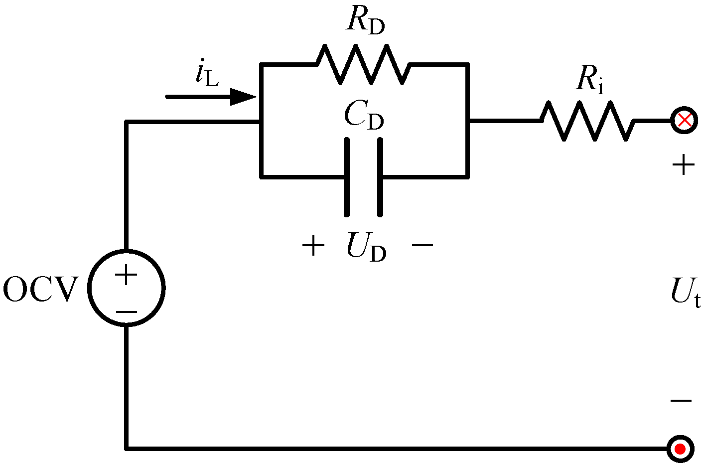
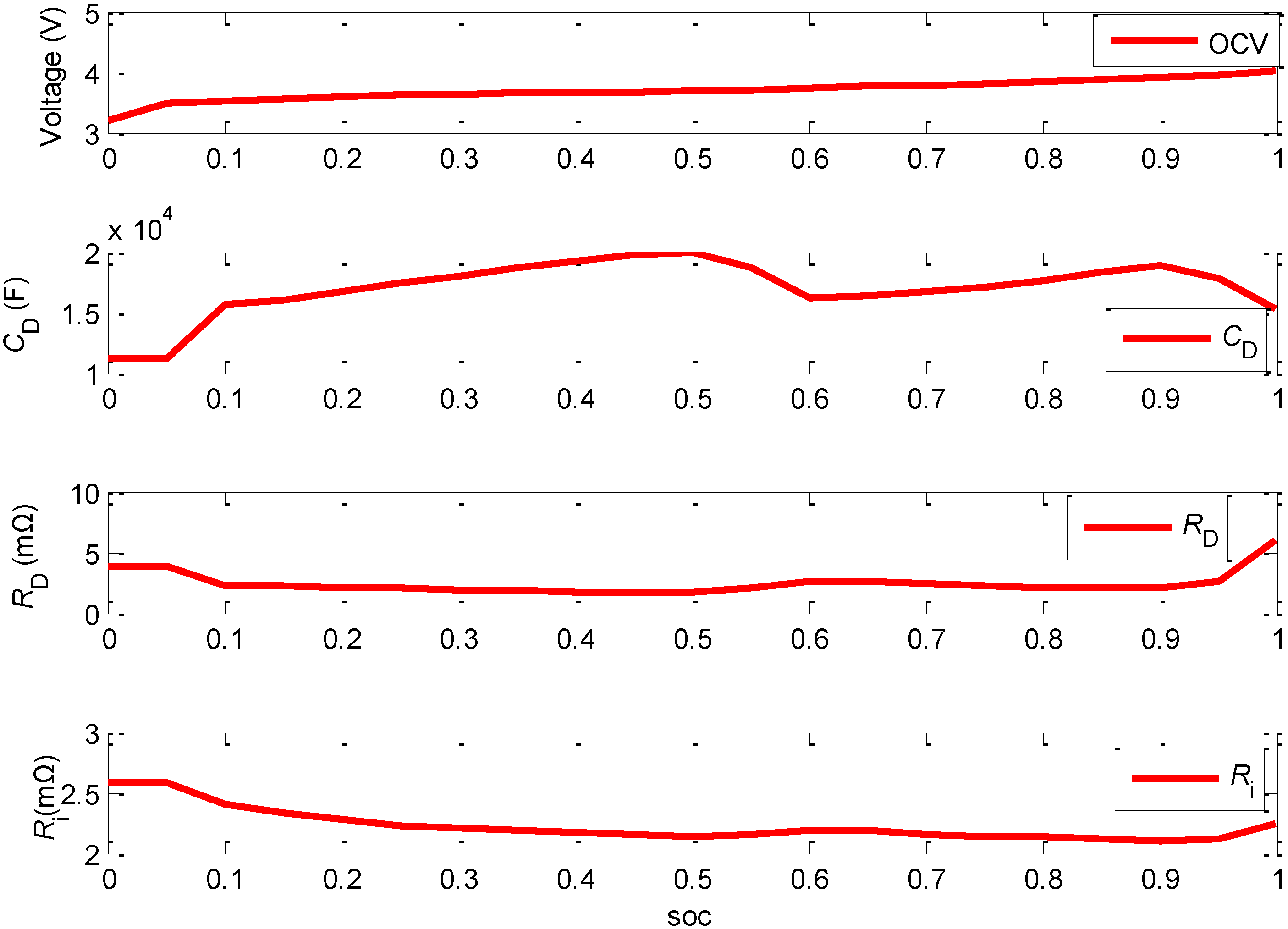
2. Lumped Parameter Battery Model

To analyze the dynamic behavior of the battery, we need to construct a battery model. The dynamics of the battery can be described as a lumped parameter battery model as shown in Figure 1, which is comprised of an open circuit voltage (OCV) part—Uoc, a resistor—Ri, and an resistance-capacitor (RC) network connected in series. The resistor Ri describes the electrical resistance of various battery components with the accumulation and dissipation of charge in the electrical double-layer. The RC network describes the mass transport effects and dynamic voltage performances, and the elements of RD and CD are accordingly described as the diffusion resistance and diffusion capacitance. iL is the load current (positive for discharge, negative for charge) and Ut is the terminal voltage. The UD describes the diffusion voltage arising from the diffusion resistance.
Figure 1. Schematic diagram of lumped parameter battery mode. OCV: open circuit voltage.
Energies 07 06783 g001
The identified parameters of OCV, CD, RD and Ri are plotted in Figure 2. The detailed parameter identification process can be found in [5].
Figure 2. The parameters’ change under different state of charge (SOC).
Energies 07 06783 g002
The electrical behavior of the battery can be expressed by the battery model through the following equation:
{ U ˙ D = 1 C D R D U D + 1 C D i L U t = U oc U D i L R i
To make the Equation (1) available for numerical calculation, it should be discretized by:
{ U t ( k ) = U oc ( k ) R i i L ( k ) R D i D ( k ) i D ( k ) = ( 1 ( 1 exp ( Δ t / τ ) ) Δ t / τ ) i L ( k ) + ( ( 1 exp ( Δ t / τ ) ) Δ t / τ exp ( Δ t / τ ) ) i L ( k 1 ) + exp ( Δ t / τ ) i D ( k 1 )

3. Dynamic Optimization Problem

Compared with rule-based algorithms, the dynamic optimization approach can find the optimized control strategy relying on a dynamic model [20,21,22]. Given the suitable models and constrains of the system, the DP-based algorithm can obtain the optimal operating strategy minimizing the system’s operation cost with subject to the diverse constraints. Based on Bellman’s principle, a numerical-based DP approach is adopted in this paper to solve this finite horizon dynamic optimization problem. Section 3.1 gives a detailed description of the basic idea of DP application in this article, Section 3.2 illustrates the simulation results, and Section 3.3 describes the abstracted charging rules based on analyzing the DP simulation results.

3.1. Problem Definition

In the discrete-time format, a model of the battery can be expressed as [23,24]:
x(k + 1) = f(x(k), u(k))
where u(k) is the vector of control variable such as desired charging current I. The x(k) is the state vector of the system such as SOC of the battery and the diffusion voltage UD of the battery. The sampling time for the control problems can be selected to be 1 s. Therefore, from Equations (1)–(3), we can surmise that the control process can be expressed by the following format:
( U D ( k + 1 ) S O C ( k + 1 ) ) = ( exp ( Δ t / τ ) 0 0 1 ) ( U D ( k ) S O C ( k ) ) + ( R D ( 1 exp ( Δ t / τ ) ) Δ t 3600 Q ) i L ( k )
The optimization goal is to find the control input u(k) to minimize a cost function, which consists of the weighted sum of energy loss and the charging time [25,26]. The cost function to be minimized has the following form:
J =   k = 0 N 1 L ( x ( k ) , u ( k ) ) = k = 0 N 1 ( ( 1 β ) L time ( k ) + β L loss ( k ) )
where N is the duration of the charging process and the L(x(k),u(k)) is the instantaneous cost including energy loss Lloss(k) and charging time cost Ltime(k). It should be mentioned that Lloss(k) is calculated by the following equation:
Lloss (k) = iL (k)2Ri + iD (k)2RD
For an energy-only problem, the weight factor β is set to be one. While for a time-only problem, the weight factor β should be set to zero. The case 0 < β < 1 represents a comprehensive problem which considers the cost of charging loss and charging time. During the optimization, it is necessary to impose the following inequality constraints to ensure safe/reasonable operation of the battery:
{ I min I ( k ) I max U t _ min U t ( k ) U t _ max U D _ min U D ( k ) U D _ max
where the I(k) is the charging current of the battery in the step k, the Imin and Imax are the lower and upper bound of I(k), the Ut(k) is the terminal voltage of battery, the UD(k) is the diffusion voltage of the battery. The Ut_min, Ut_max, UD_max and UD_max are the bounds for Ut(k) and UD(k). In addition, to promote the calculating efficiency and satisfy the systems properties, besides above basic constraints, other constraints are also needed:
{ S O C min S O C ( k ) S O C max T min T T max
where the SOC(k) stands for the state of charge for the battery, and the T stands for the charging time. The purpose of this constraint is to promote the calculation efficiency and at the same time to make sure the charging time at the reasonable range. All the bounds for the parameters are displayed in Table 1, while the detailed discretization for control and state parameters are displayed in Table 2.
Table 1. The comparison of different methods.
BoundValueBoundValue
Imin (A)−96UD_min (V)−0.2
Imax (A)0UD_max (V)0
Ut_min (V)3.0SOCmin0.2
Ut_max (V)4.05SOCmax1
Tmin (s)1000Tmax (s)2700
Table 2. The discretization for control and state parameters.
ParameterSOCUDI
Range[0.2, 1][−0.2, 0.2][−96, 96]
Discretization0.01420.004 V0.8 A

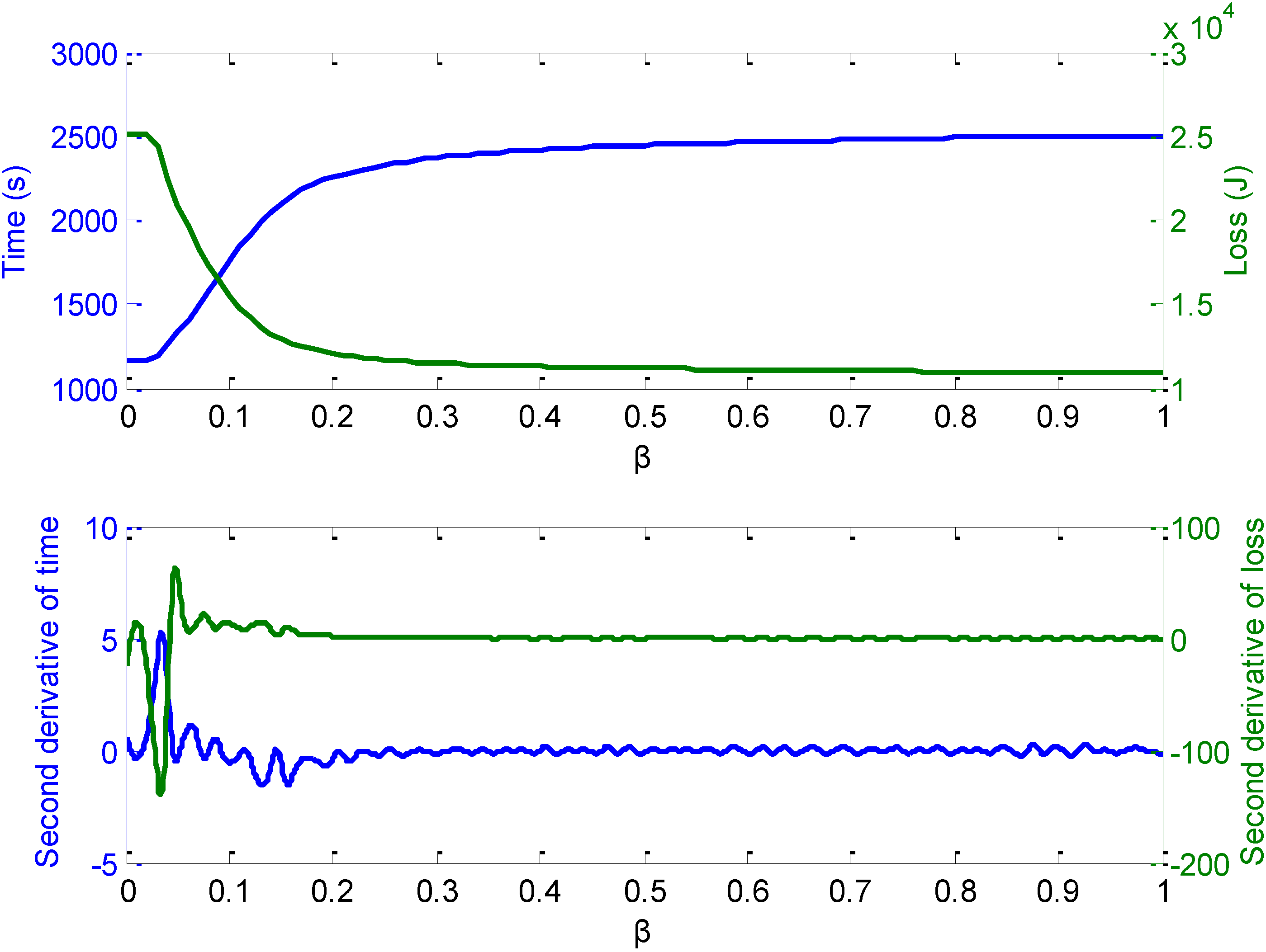
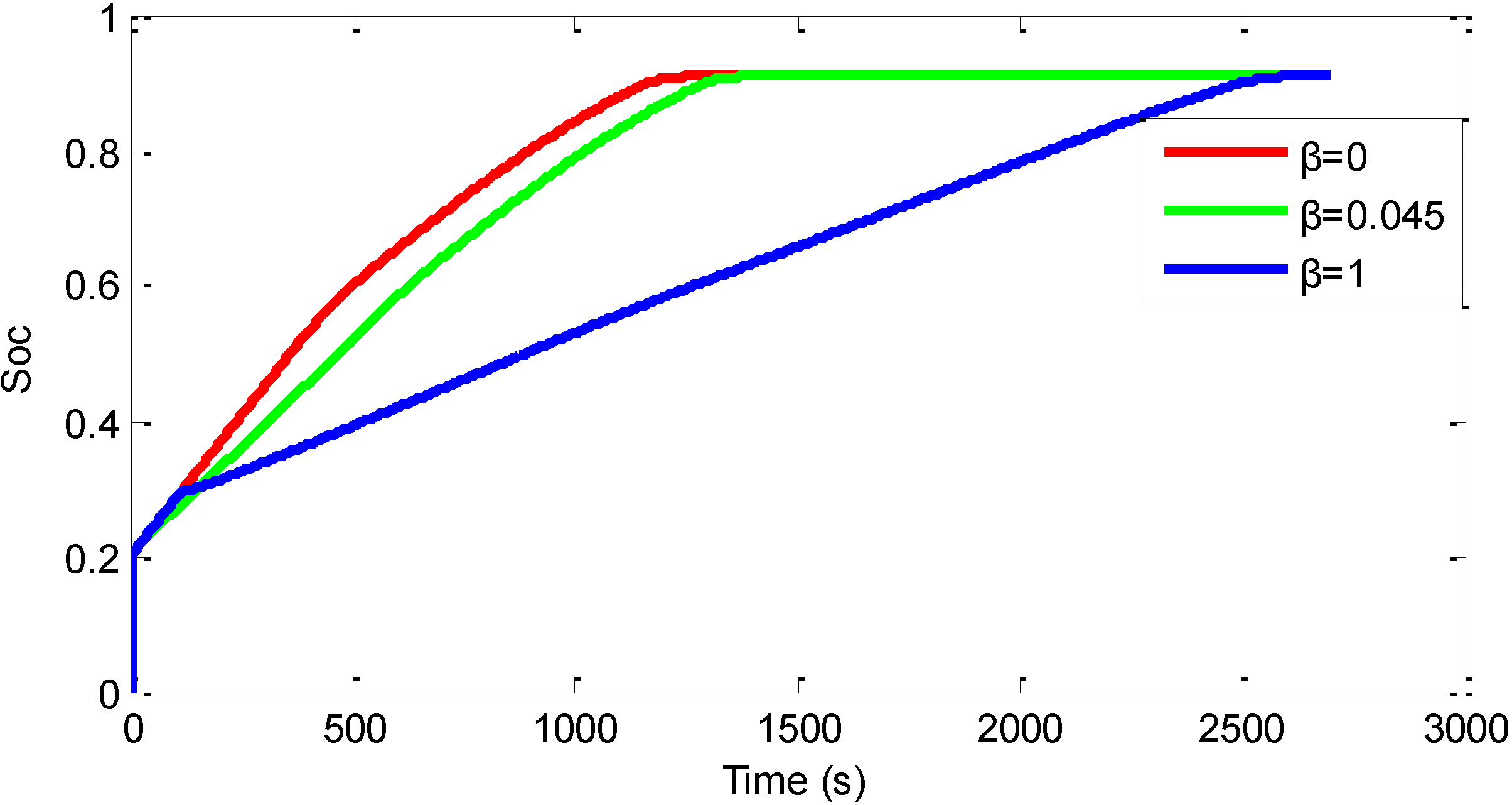
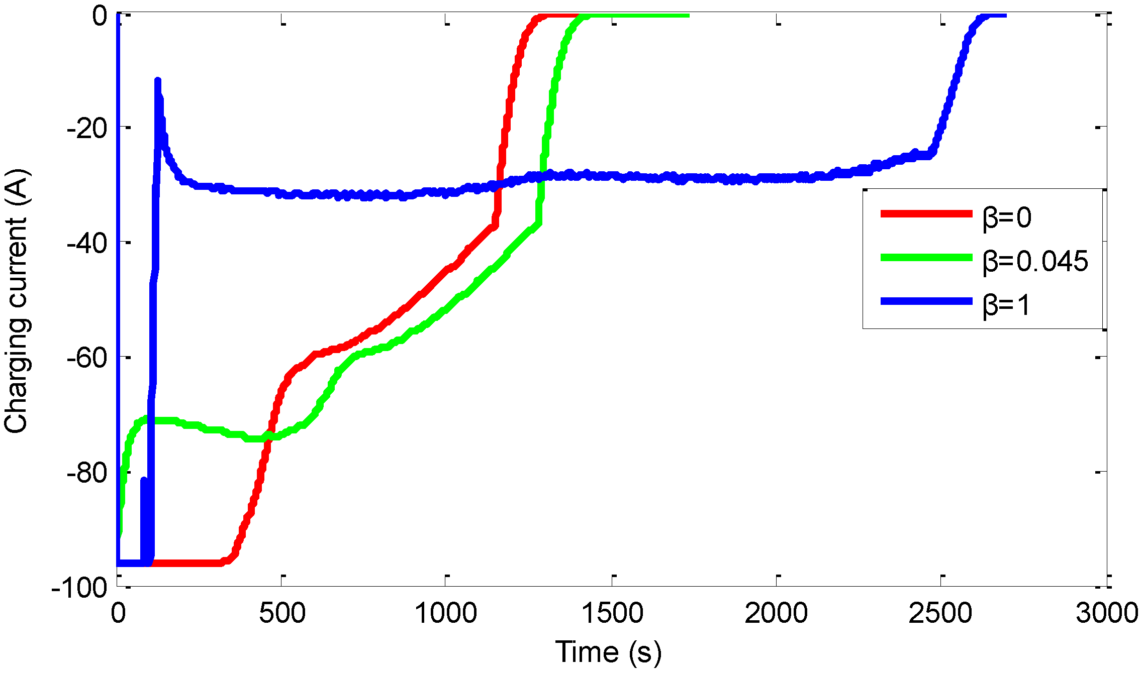
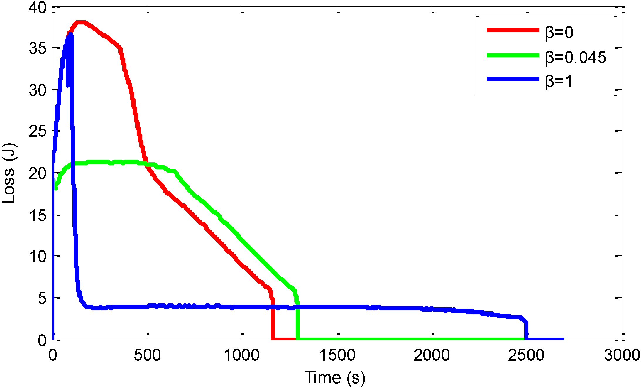
3.2. The Simulation Results

The DP procedure described above produces an optimal, time-varying, state-feedback control law. Figure 3 shows the simulation results when β varies from 0 to 1 with the increment of 0.01.
Figure 3. The time and loss change under different β.
Energies 07 06783 g003
The first plot presented in Figure 3 shows that the charging time and energy loss trend with the increase of β and the second picture describes the second derivative of the time and loss. From the first plot, we can find that when β is set to zero, which means the optimal goal is to minimize the charging time only, the charging time is only 1167 s with the charging loss reaching a peak of 25,150 J. When β is set to zero, which means the optimal goal is to minimize the energy loss only, the charging time peaks at about 2500 with the charging loss decreased to only about 10,990 J. The longest charging time is 2500, which is results of that we set the time horizon from 0 to 2700 and the final state of SOC has also be constrained to be more than 0.9. From the second picture, we can get that the inflection point for the charging time and charging loss is between 0.044 and 0.046. Considering the balance between the charging loss and charging time, we set β to be 0.045 for further discussion.
Figure 4 is the dynamic property of SOC under different β. It is apparent that when β is small which means that we pay more attention to the charging time, the SOC increases faster than that when β is big, which means that we pay more attention to the charging loss.
Figure 4. The dynamic property of SOC with different β.
Energies 07 06783 g004
This is mainly due to the different control current as presented in Figure 5. From Figure 5, we can get that when β is zero the charging current will be the maximum charging current at the initial stage and then it will decrease due to the constraint of Ut, which is called the constant-voltage charging. It is noticeable that when β is set to be 1 the charging current tends to be low.
Figure 5. The dynamic property of charging current with different β.
Energies 07 06783 g005
The big current will need less charging time but will lead to the big charging loss as displayed in the Figure 6. When β is set to be 0.045, the dynamic property of the charging loss and charging time is between that when β is set to be 0 or 1, with the charging loss decreasing 13.9% and the charging time increasing 10.09% compared with that when β is set to be 0.
Figure 6. The dynamic property of energy loss under different β.
Energies 07 06783 g006

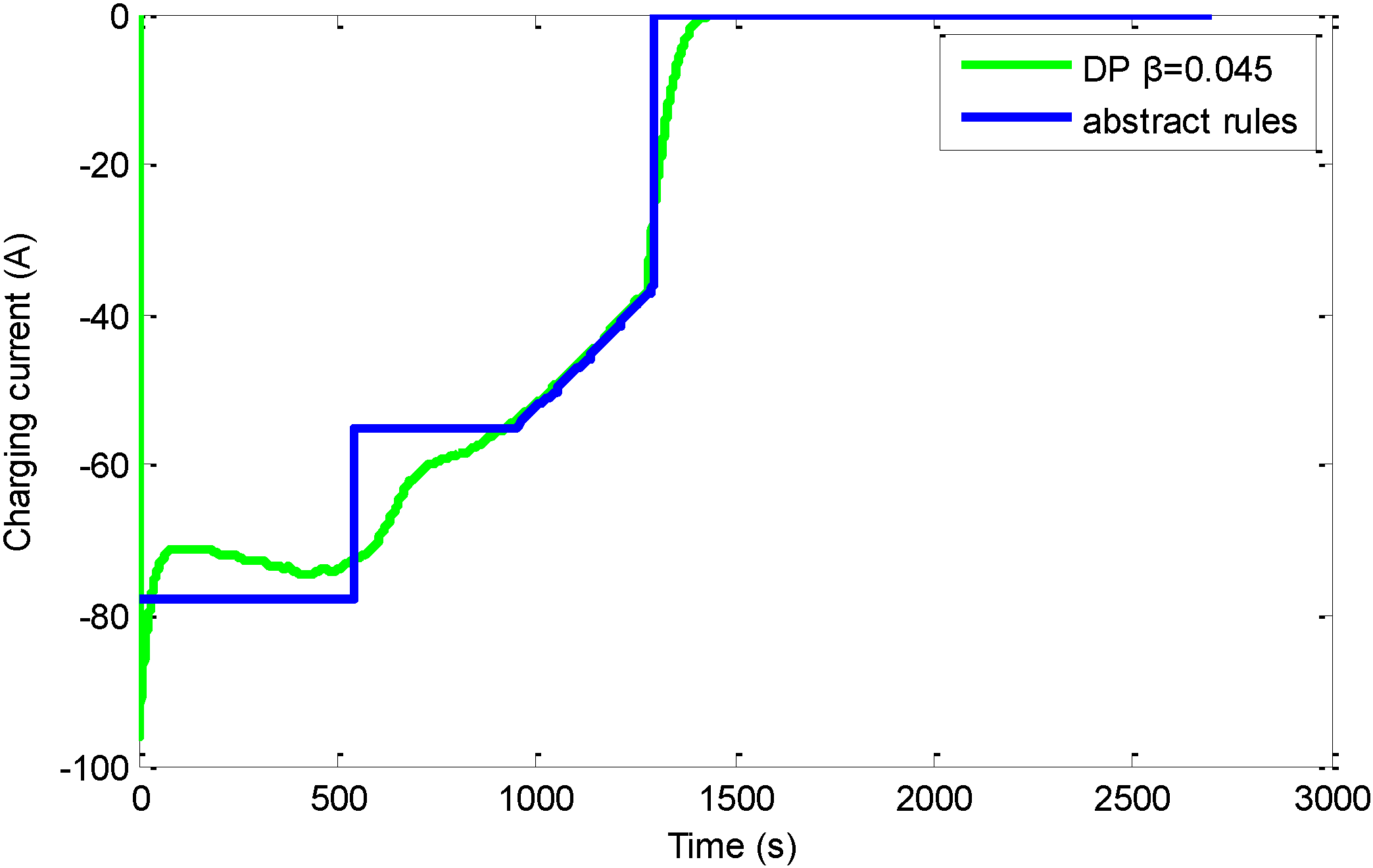
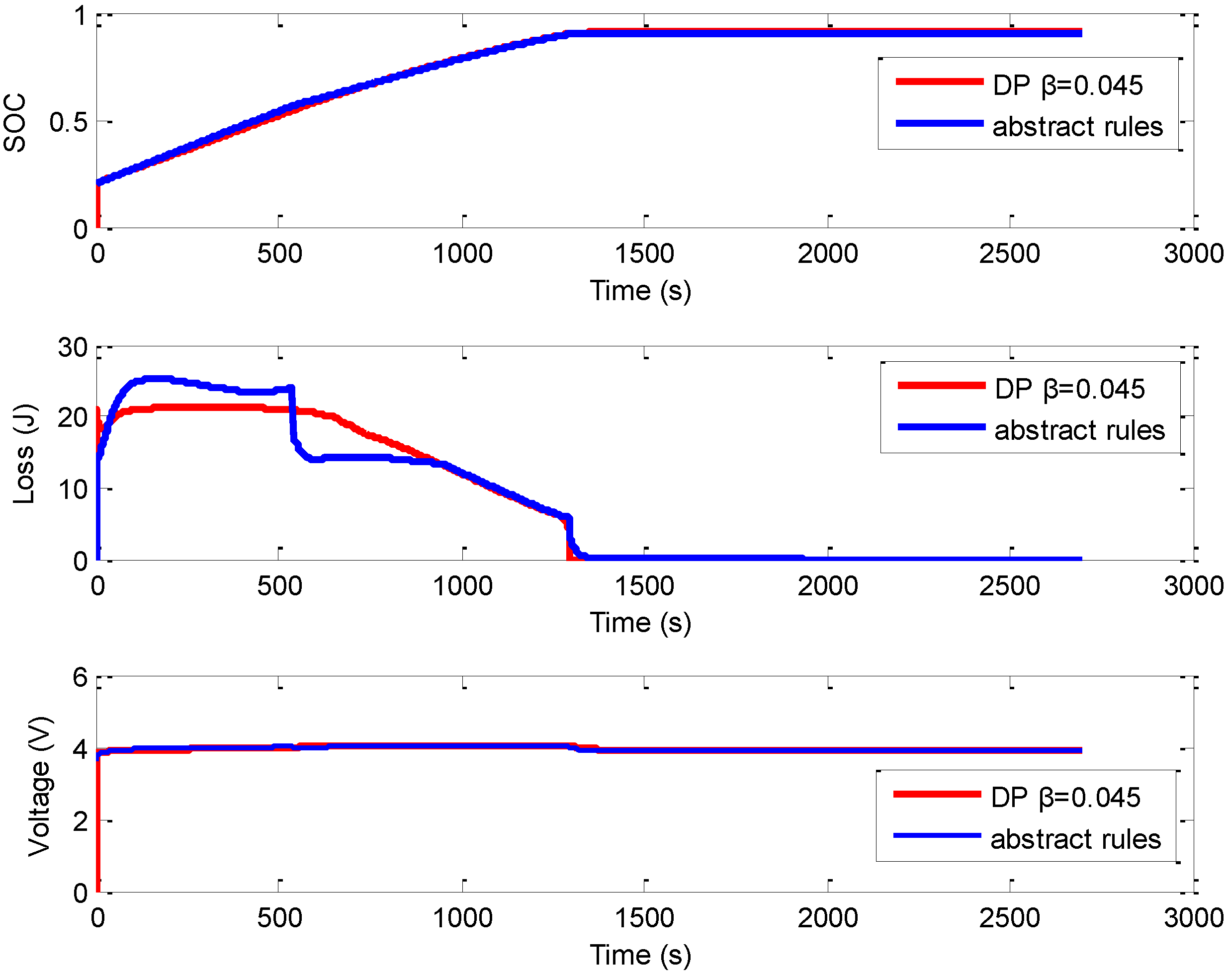
3.3. The Abstracted Control Strategy and Simulation Results

The DP algorithm based control policy is not implementable in real charging conditions because it requires the charging current changing frequently with high frequency and, according to Bellman’s principle, the DP process needs backward calculation to find the optimal control strategy. Nonetheless, analyzing its behavior provides useful insight into possible improvement of the rule-based controller [27]. Based on the above simulation results, here we abstract the charging strategy as illustrated in Figure 7. Compared with DP simulation results, the abstracted charging current is implementable in real charging conditions as it only has two CC stages.
Figure 7. Abstract charging strategy.
Energies 07 06783 g007
Figure 8 shows the comparison of DP results and abstracted rules in terms of SOC, loss and terminal voltage. It is worth noting that the performance of the abstracted charging strategy is similar to the DP result with the charging time (SOC from 20% to 90%) increasing 0.3% and charging loss increasing 0.79%.
Figure 8. The performance of the abstracted charging current.
Energies 07 06783 g008

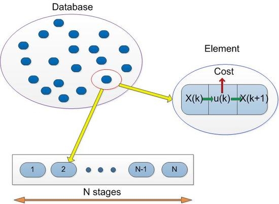
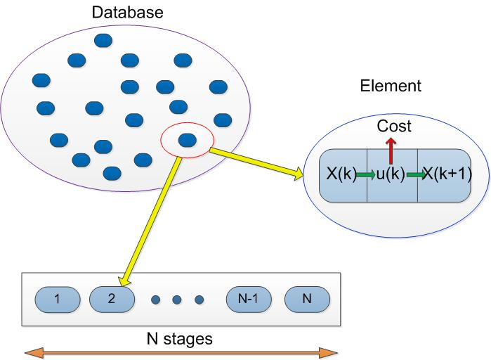
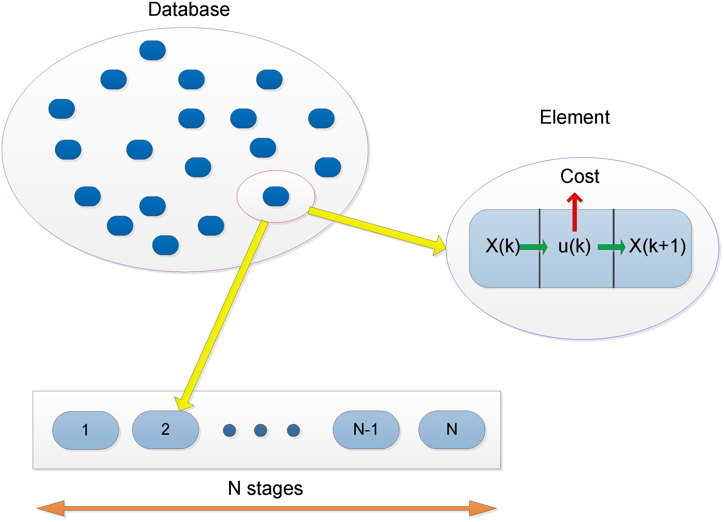
4. The Database Based Dynamic Programing Optimal Method

The above abstracted charging strategy is based on the analysis of the DP simulation results. The drawback of the method is that it has inevitable randomness as the strategy is determined by hand. Therefore, the two-stage constant charging current and its time duration have not been optimized. Another drawback is that the abstracted rules are set to two constant charging current stages, which also contain some randomness as it neglects the effect of different number of stages. However, to find an implementable, and suboptimal charging strategy according to charging requirements by analyzing DP results will directly increase the demensions of equation from two to three. Moreover, when we want to analyze the effect of different charging stratergies, the repeating calculation problem exists in the grid points whereby the calculation time and memory requirements for the computer are not acceptible. This section proposed a database processing method wich can transfer the discrete time problem into a discrete stages problem, and can greatly promote the calculation efficiency. Section 4.1 describes the working principle of the database, the construction process of the database is described in Section 4.2, while the simulation results are given in Section 4.3.

4.1. The Operation Principle of the Database

The main idea of the database is that the whole dynamic optimization process has been broken down into several fragments. Then each fragment can be regarded as a single process. The single process has the same dynamic properties based on different initial states and controls. Most of the time, the initial state of first fragment is known, but the others should be determined by the former fragment’s final state. It is obvious that, if we select proper control for each fragment, then the whole dynamic process could be suboptimal compared with conventional DP simulation results. The key point here is that for each fragment, when we select the control and calculate the costs, we will select them from the database instead of calculating. The database is calculated off-line. Each of the database’s elements should contain initial states, controls, the final states under such controls and the costs. Figure 9 shows the operation process of the database method. This picture displayed how the elements in the database are used to determine the control rules for an N-stages problem. Once the database is constructed, the design of control rules becomes a selection process, what we need to do is to select suitable elements that contain the different controls and at the same time we have to make sure that the initial state x(0) of the K + 1 element is the same as the final state x(N − 1) of the K element. This is to make sure the state is serial. For the selection of the first and final stage, the condition may be different. For most of the cases, the initial state in the first stage will be known. In this situation, we should select the elements according to the controls and initial states. For the final state, if the target problems have requirements for the final state, we have to select the element according to the controls and the final state requirements.
Figure 9. The operation process of the database.
Energies 07 06783 g009

4.2. The Construction of Database

Before calculating the database we should determine the states and controls. According to the above discussion, we regard battery SOC and the diffusion voltage UD as the state varibles, the constant charging current and duration as the control varibles, the enegy loss and charging time as the costs. In the final stage charging current will decrease to avoid the terminal voltage Ut exceeding constrains. Therefore, in the final stage another sub database needs to be built, in which the battery SOC and the diffusion voltage UD is regarded as the states, the initial charge current is regarded as controls, while the charging time and energy loss are still regarded as the costs. In the sub database, as mentioned above, the charging current may not stay constant and will decrease to make sure the terminal voltage Ut stays within the constrains, so in the final stage the charging currents is just an initial constant charging current and then the current will become the current for constant-voltage charging.
After the database is determined, it will be used to find the control strategy by DP and the control strategy is implementable in real conditions. To use the databases by DP, the former discrete-time format should be changed into the discrete-stage format. The model of the battery can also be expressed as Equation (3) where the control varibles of u(k) will become from charging current only to charging time and charging duration. This change will allso depend on whether the curent stage is the final stage. If it is the final stage, then the control will still be charging current. The state vector of x(k) will be the battery SOC, the diffusion voltage UD and charging stages. The control process can be expressed by the following format:
( s t a g e ( k + 1 ) U D ( k + 1 ) S O C ( k + 1 ) ) = ( f s t a g e ( x ( k ) ) f U D ( x ( k ) , u ( k ) ) f S O C ( x ( k ) , u ( k ) ) )
where fUD(x(k), u(k)) and fSOC(x(k), u(k)) are calculated according to Equations (1) and (4). The optimization goal (Equation (5)) and constrains (Equation (7)) is still used in this section, but constrains in Equation (8) should be as follows:
S O C min S O C ( k ) S O C max
Constrains of charging time is neglected. This can give us more general results about the charging time and energy loss. Another reason for that is that it can help us reduce the dimension of the problem, which means that if we want to constrain the charging time, the dimension of the problem will increase from three to four, which will increase the memory requirements for the computer.

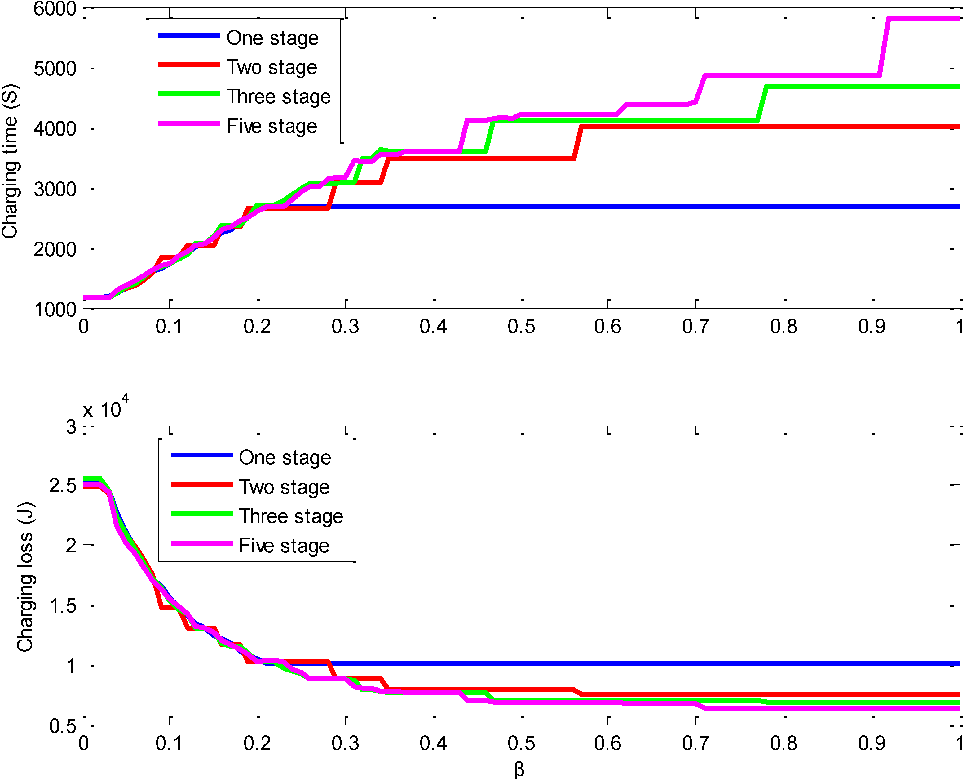
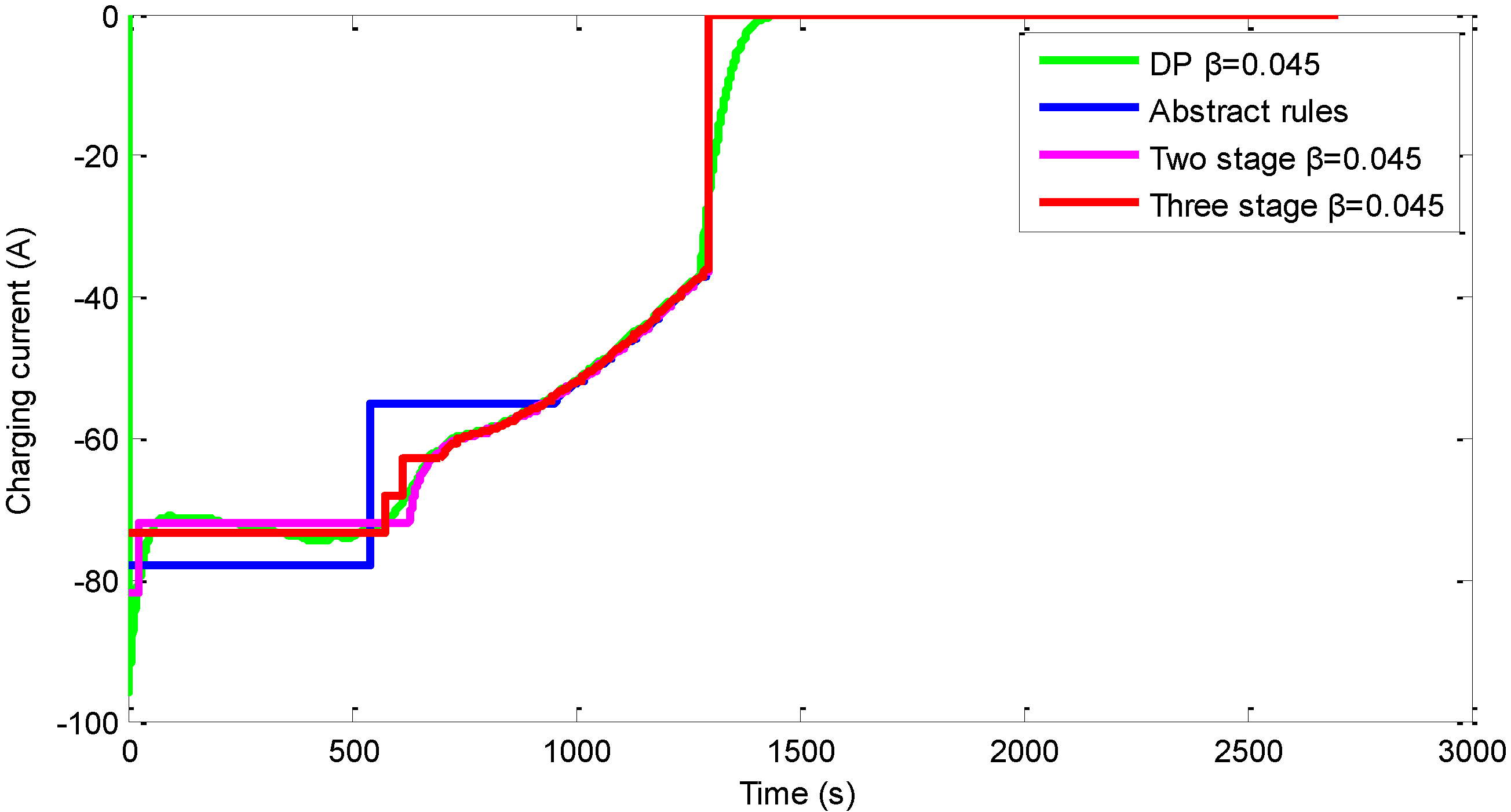
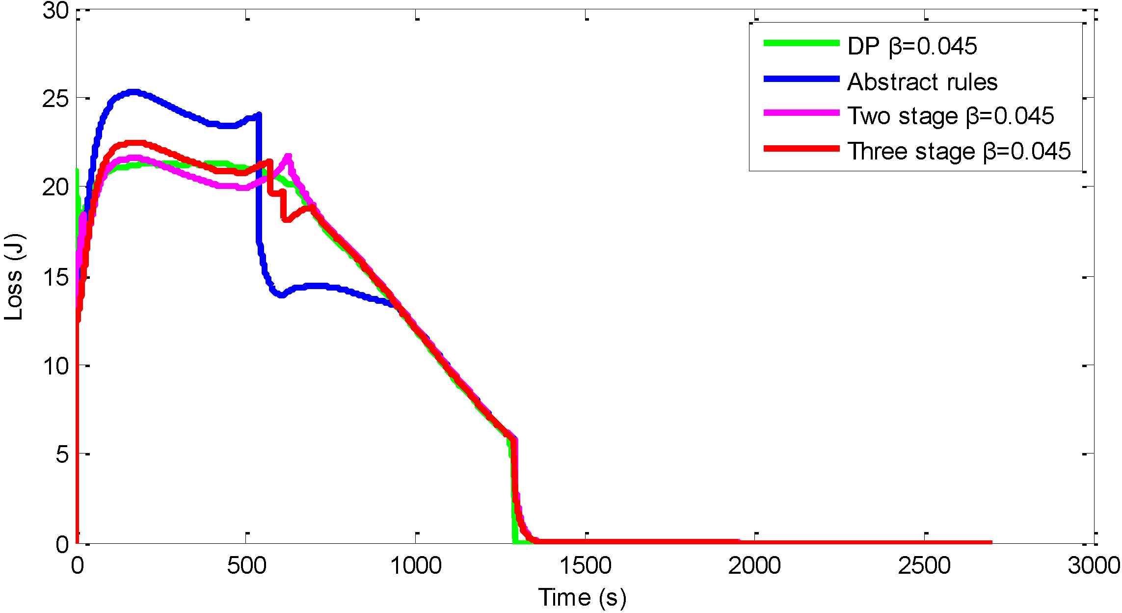
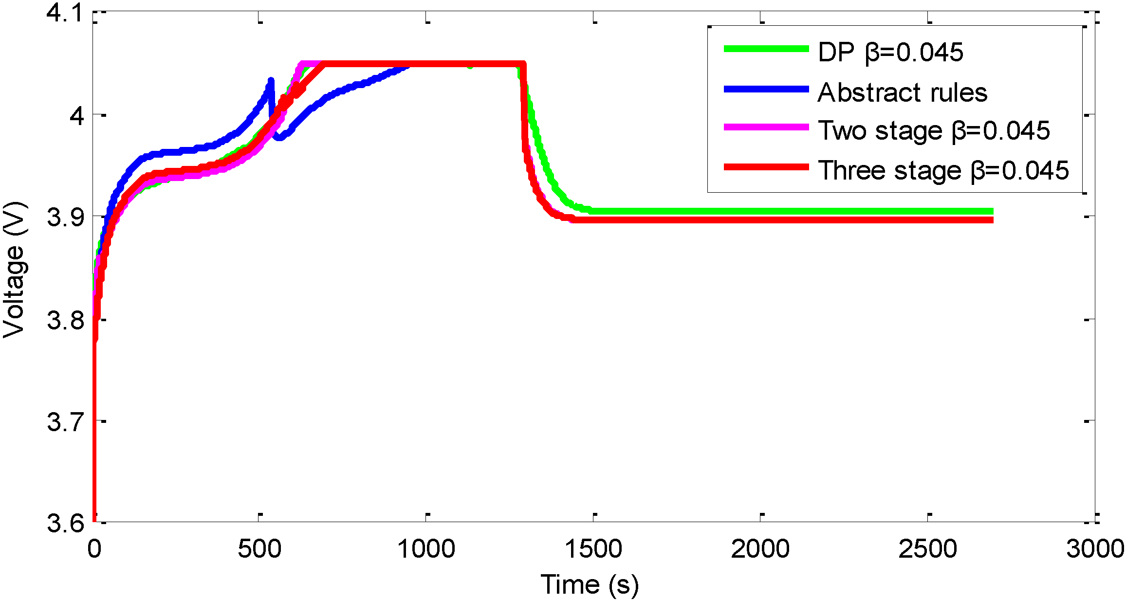
4.3. The Simulation Results for the Databased Dynamic Programing Method

The above-described database based DP method can easily and efficiently be realized to find the optimal charging strategy under different charging stage requirements. The databased DP results for one stage, two stages, three stages and five stages are shown in Figure 10. The trend of the charging time and charging loss is similar with that in Figure 3. From the trend we can see that the charging time and charging loss have negative correlation, which means that in the optimal conditions if the charging time decreases then the charging loss will increase. Another observation we can make is that when β is less than 0.3 the performance of the different stages are not significantly different. When β is bigger than 0.3, the more stages means more flexibility to realize the charging requirements.
Figure 10. The charging time and charging loss change with the variation of β under different charging stages.
Energies 07 06783 g010
Figure 11 shows that the charging current comparison of the three different methods: DP method, abstracted rules and database-based DP. We can see clearly from the picture that the two stages and three stages charging strategy can follow the optimal charging current better than the abstracted rules.
Figure 11. The charging current comparison of the three different methods.
Energies 07 06783 g011
The same conclusion can be obtained from the charging loss property in Figure 12. However, the charging loss property is similar in the three-stage strategy and two-stage strategy.
Figure 12. The charging loss comparison of three different methods.
Energies 07 06783 g012
Figure 13 shows the terminal voltage property in the charging process. The two stages and three stages charging strategy can follow the optimal charging voltage very well, while the abstract rules have different properties in the CV charging conditions.
Figure 13. The terminal voltage comparison of three different methods.
Energies 07 06783 g013
The comparison of the charging cost of the different methods is shown in the Table 3. Compared with the performance of abstracted control strategy, the database-based DP method has better performance and is more closely to the DP results. The results of the three-stage strategy are better than that of two-stage strategy obtained from the database based DP method. This is reasonable, because if the number of stages is big enough, then the results will be the same as the results from DP. The small difference of the results also verifies the advantages of the database based DP method. The first advantage is that the control strategy obtained from the database based DP method is implementable compared with DP, and another advantage is that it can effectively find the suboptimal control strategy without the repeated calculation.
Table 3. The simulation results comparison of different methods.
MethodCharging time (s)Charging loss (kJ)
DP β = 0.045129421.65
Abstract rules129821.82
Database (two stage) β = 0.045129821.57
Database (three stage) β = 0.045129421.67

5. Conclusions

Based on the lumped parameter battery model, the DP algorithm is iteratively used when β is set to be different values. The calculation results with the DP algorithm shows that the charging time and charging loss have negative correlation, which means that, in optimal conditions, the charging time decreases with the increasing of the charging loss. The DP algorithm based control strategy is not implementable in real charging conditions because, according to Bellman’s principle, the DP process needs backward calculation to find the optimal control strategy and it requires the charging current changing frequently with high frequency, which is not easy to realize. Consequently, this paper proposed an implementable charging strategy by analyzing the simulation results of DP algorithm when β is set to be 0.045. It is noticeable that the performance of the abstracted charging strategy is similar to the DP algorithm results with the charging time (SOC from 20% to 90%) increasing 0.3% and charging loss increasing 0.79%. To reduce the randomness of the abstracted charging rules, this paper proposed a database-based method to optimize the implementable charging strategy. The advantages of the database-based method are that it can avoid the repeat calculation and the calculation result is implementable compared with conventional DP algorithm. The simulation results show that the proposed database-based DP method has better performance compared with abstracted rules, which is obtained from analyzing the simulation results of the conventional DP algorithm.

Acknowledgments

The authors gratefully acknowledge the support from the National Natural Science Foundation of China (Grant No. 51175040), the research fund from Beijing Scientific Committee (Grant No. Z12110900660000) and the Research Fund for the Doctoral Program of Higher Education of China (Grant No. 20111101110037).

Author Contributions

Rui Xiong proposed the main idea and mathematical method, Shuo Zhang and Chengning Zhang developed the numerical method and carried out the simulation and verification, and Wei Zhou formatted the manuscript for submission.

Conflicts of Interest

The authors declare no conflict of interest.

References

  1. Chen, L.-R.; Wu, S.-L.; Chen, T.-R.; Yang, W.-R.; Wang, C.-S.; Chen, P.-C. Detecting of Optimal Li-Ion Battery Charging Frequency by Using AC Impedance Technique. In Proceedings of the 4th IEEE Conference on Industrial Electronics and Applications (ICIEA 2009), Xi’an, Shaanxi, China, 25–27 May 2009; pp. 3378–3381.
  2. Xiong, R.; Sun, F.; Chen, Z.; He, H. A data-driven multi-scale extended Kalman filtering based parameter and state estimation approach of lithium-ion polymer battery in electric vehicles. Appl. Energy 2014, 113, 463–476. [Google Scholar] [CrossRef]
  3. Xiong, R.; Sun, F.; Gong, X.; Gao, C. A data-driven based adaptive state of charge estimator of lithium-ion polymer battery used in electric vehicles. Appl. Energy 2014, 113, 1421–1433. [Google Scholar] [CrossRef]
  4. Xiong, R.; Sun, F.; Gong, X.; He, H. Adaptive state of charge estimator for lithium-ion cells series battery pack in electric vehicles. J. Power Sources 2013, 242, 699–713. [Google Scholar] [CrossRef]
  5. Xiong, R.; Sun, F.; He, H.; Nguyen, T. A data-driven adaptive state of charge and power capability joint estimator of lithium-ion polymer battery used in electric vehicles. Energy 2013, 63, 295–308. [Google Scholar] [CrossRef]
  6. Yilmaz, M.; Krein, P.T. Review of battery charger topologies, charging power levels, and infrastructure for plug-in electric and hybrid vehicles. IEEE Trans. Power Electron. 2013, 28, 2151–2169. [Google Scholar] [CrossRef]
  7. Ahn, C.S.; Li, C.-T.; Peng, H. Optimal decentralized charging control algorithm for electrified vehicles connected to smart grid. J. Power Sources 2011, 196, 10369–10379. [Google Scholar] [CrossRef]
  8. Bashash, S.; Moura, S.J.; Forman, J.C.; Fathy, H.K. Plug-in hybrid electric vehicle charge pattern optimization for energy cost and battery longevity. J. Power Sources 2011, 196, 541–549. [Google Scholar] [CrossRef]
  9. Bashash, S.; Moura, S.J.; Fathy, H.K. On the aggregate grid load imposed by battery health-conscious charging of plug-in hybrid electric vehicles. J. Power Sources 2011, 196, 8747–8754. [Google Scholar] [CrossRef]
  10. Carcone, J.A. Performance of lithium-ion battery systems. In Proceedings of the WESCON/94. Idea/Microelectronics. Conference Record, Anaheim, CA, USA, 27–29 September 1994; pp. 242–248.
  11. Tseng, S.-Y.; Shih, T.-C.; Fan, S.-Y.; Chang, G.-K. Design and implementation of lithium-ion/lithium-polymer battery charger with impedance compensation. In Proceedings of the International Conference on Power Electronics and Drive Systems (PEDS 2009), Taipei, Taiwan, 2–5 November 2009; pp. 866–870.
  12. Dearborn, S. Charging Li-ion batteries for maximum run times. Power Electron. Technol. 2005, 31, 40–49. [Google Scholar]
  13. Zhang, S.S.; Xu, K.; Jow, T.R. Study of the charging process of a LiCoO2-based Li-ion battery. J. Power Sources 2006, 160, 1349–1354. [Google Scholar] [CrossRef]
  14. Liu, Y.-H.; Teng, J.-H.; Lin, Y.-C. Search for an optimal rapid charging pattern for lithium-ion batteries using ant colony system algorithm. IEEE Trans. Ind. Electron. 2005, 52, 1328–1336. [Google Scholar] [CrossRef]
  15. Hsieh, G.-C.; Chen, L.-R.; Huang, K.-S. Fuzzy-controlled Li-ion battery charge system with active state-of-charge controller. IEEE Trans. Ind. Electron. 2001, 48, 585–593. [Google Scholar] [CrossRef]
  16. Surmann, H. Genetic optimization of a fuzzy system for charging batteries. IEEE Trans. Ind. Electron. 1996, 43, 541–548. [Google Scholar] [CrossRef]
  17. Ullah, Z.; Burford, B.; Dillip, S. Fast intelligent battery charging: Neural-fuzzy approach. IEEE Aerosp. Electron. Syst. Mag. 1996, 11, 26–34. [Google Scholar] [CrossRef]
  18. Chen, L.-R.; Hsu, R.C.; Liu, C.-S. A design of a grey-predicted Li-ion battery charge system. IEEE Trans. Ind. Electron. 2008, 55, 3692–3701. [Google Scholar] [CrossRef]
  19. Hu, X.; Li, S.; Pen, H.; Sun, F. Charging time and loss optimization for LiNMC and LiFePO4 batteries based on equivalent circuit models. J. Power. Sources 2013, 239, 449–457. [Google Scholar] [CrossRef]
  20. Lin, C.C.; Peng, H.; Grizzle, J.W.; Kang, J.M. Power management strategy for a parallel hybrid electric truck. IEEE Trans. Control Syst. Technol. 2003, 11, 839–849. [Google Scholar] [CrossRef]
  21. Brahma, A.; Guezennec, Y.; Rizzoni, G. Dynamic optimization of mechanical/electrical power flow in parallel hybrid electric vehicles. In Proceedings of the 5th International Symposium Advanced Vehicle Control, Ann Arbor, MI, USA, 22–24 August 2000.
  22. He, H.; Tang, H.; Wang, X. Global optimal energy management strategy research for a plug-in series-parallel hybrid electric bus by using dynamic programming. Math. Probl. Eng. 2013, 2013. [Google Scholar] [CrossRef]
  23. Wang, W.; Lukic, S.M. Dynamic programming technique in hybrid electric vehicle optimization. In Proceedings of the 2012 IEEE International Electric Vehicle Conference (IEVC), Greenville, SC, USA, 4–8 March 2012; pp. 1–8.
  24. Bertsekas, D.P. Dynamic Programming and Optimal Control; Athena Scientific: Belmont, MA, USA, 1995. [Google Scholar]
  25. Zou, Y.; Hou, S.J.; Han, E.L. Dynamic programming-based energy management strategy optimization for hybrid electric commercial vehicle. Automot. Eng. 2012, 34, 663–668. [Google Scholar]
  26. Zou, Y.; Hou, S.; Li, D.; Gao, W.; Hu, X. Optimal energy control strategy design for a hybrid electric vehicle. Discret. Dyn. Nat. Soc. 2013, 2013. [Google Scholar] [CrossRef]
  27. Zhang, S.; Zhang, C.; Han, G.; Wang, Q. Optimal control strategy design based on dynamic programming for a dual-motor coupling-propulsion system. Sci. World J. 2014, 2014. [Google Scholar] [CrossRef]

