Performance of Different Experimental Absorber Designs in Absorption Heat Pump Cycle Technologies: A Review


Abstract
: The absorber is a major component of absorption cycle systems, and its performance directly impacts the overall size and energy supplies of these devices. Absorption cooling and heating cycles have different absorber design requirements: in absorption cooling systems, the absorber works close to ambient temperature, therefore, the mass transfer is the most important phenomenon in order to reduce the generator size; on the other hand, in heat transformer absorption systems, is important to recover the heat delivered by exothermic reactions produced in the absorber. In this paper a review of the main experimental results of different absorber designs reported in absorption heat pump cycles is presented.1. Introduction
As the proven reserves of fossil fuels decrease and the Kyoto Protocol has urged nations to mitigate the negative effects of greenhouse gases, renewable energy sources and the efficient use of energy have become important topics. A main cause of energy inefficiency is the generation of waste heat and the lack of utilization of this waste heat, particularly low grade heat that is especially abundant in industry as by-products such as heat effluents, exhaust gases or cooling water. This represents a significant potential resource which to date has remained under-exploited, mainly because of the cost of obtaining useful exergy and energy out of low grade heat. Although low grade heat generally remains in the form of waste heat from the process industries, other examples of low grade heat include renewable energy resources, e.g., solar, geothermal and biomass [1].
Absorption Heat Pumps (AHPs) are a natural choice for cooling and heating applications as they can improve the overall energy utilization efficiency and are environmentally friendly [2,3]. In absorption machines, as used for refrigeration systems, heat pumps and heat transformers, the absorber is the ultimate component in optimizing the Coefficient of Performance (COP) of the device. The combination of heat and mass transfer leads to complicated phenomena occurring in these absorbers. The search for optimally working devices has resulted in a big number of designs. In any design three important points have to be considered [4]:
The interface surface between vapour and absorbent has to be as large as possible.
The boundary layer of the absorbent has to be refreshed continuously.
The absorption heat is to be withdrawn at nearly the same place as it is developed.
However, frequently the size of the absorber is bigger because the absorber heat and mass transfer coefficients for the working mixtures are low [5], in addition, Second Law thermodynamic analysis shows the highest exergy loss occurs in the absorber, due to the temperature difference between the absorber and the surroundings [6–9]. This can be reduced by increasing the surface area of the absorber, consequently increasing its cost. Numerical analysis shows than heat and mass transfer absorber effectiveness has a significant influence on the absorber performance cycle. Mass transfer absorber effectiveness can reduce the generator heat power supply when the absorber dilution has a great value and it reduces the exergy loss when high heat transfer effectiveness values are achieved, therefore, increasing the COP [10,11]. In order to increase the heat and mass transfer coefficients, several absorption designs have been reported, which use different ways for that: increasing the heat and mass transfer area, increasing the vapour refrigerant pressure or improved mixing of working fluids. The aim of this paper is to provide a background with a review of the literature on absorber design and its performance in absorption cycles. It is expected that this paper will be useful for any researcher in the field of absorption cycle technologies.
2. Absorbers in Cooling Absorption Cycles
Absorption cooling cycles produce a cooling effect by removing heat and transferring this heat to a vaporized working fluid called “refrigerant”. An absorption cooling system basically consists of an evaporator, an absorber, a generator, a condenser, an economizer and requires two fluids: the refrigerant and an absorber solution. In the absorption cooling cycle the working fluid undergoes a phase change in the condenser and evaporator, and the absorbent solution, a change in concentration in the generator and the absorber.
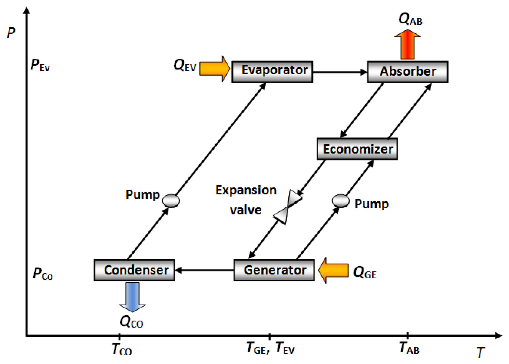
The working fluid flows into the evaporator, where it evaporates at a reduced pressure and temperature, taking heat from environment (QEV). The working fluid vapour from the evaporator is absorbed at low pressure into the concentrated absorber solution in the component called absorber. A quantity of heat (QAB) is released as much as the refrigerant vapour is absorbed. This heat is removed by some cooling fluid (air, water or another fluid) from the absorber. The diluted absorber solution in the absorber is pumped to energy recovery device called “economizer”. In this component, the concentrated absorber solution preheats the diluted absorber solution before reaching the generator. In the generator, a part of the working fluid is vaporized from the diluted absorber solution by addition of a quantity of heat (QGE) at high temperature and pressure. The working fluid vapour is condensed at high pressure and temperature in the condenser with removal of heat (QCO) to the ambient. The working fluid liquid in the condenser is returned to the evaporator through the expansion valve. Then the absorption cycle repeats from the evaporator [12]. Figure 1 shows a schematic diagram of the described cycle. In these devices, the absorber is near to ambient temperature, and the cooling effect occurs in the evaporator, however, the absorber performance directly affects the energy supply to the generator, therefore, a correct absorber design is desirable. In a cooling cycle absorber design, it is well known that the absorption of the refrigerant vapour into the working solution is possible only when the latter is sub-cooled and that the solution, upon leaving the absorber, is still sub-cooled [13]. The different kinds of absorber used in this cycle are described below.
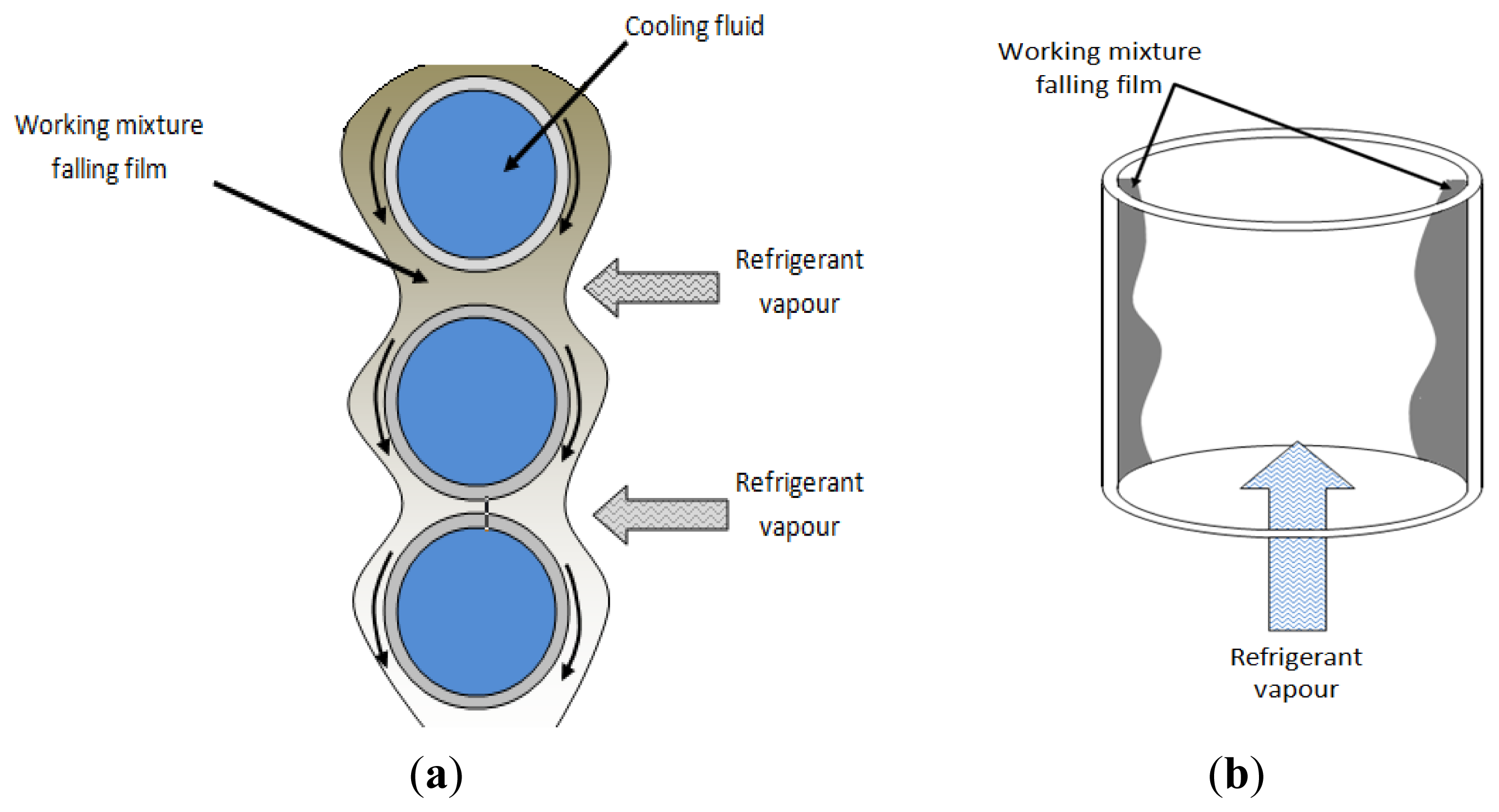
2.1. Falling Film Absorbers
Falling film absorbers are the most common type used in commercial cooling absorption machines. Falling film systems have been recommended to enhance heat and mass transfer during the absorption process. Thin falling film heat transfer mode provides a high heat transfer coefficient and is stable during operation. However, it has a wettability problem that deteriorates the absorption performance. Heat and mass transfer in a falling film absorber are largely influenced by fluid properties, geometry of heat exchanger and its operating parameters [14–16]. Figure 2 shows the different falling film absorber configurations.
Lee et al. [17] evaluated an absorber with a tube bank of four columns of six 9.5 mm nominal OD, 0.292 m long tubes installed in a shell in order to quantify the heat and mass transfer measurements for ammonia/water mixtures. For the range of experiments conducted, the absorber heat duty varied from 3.11 to 10.2 kW, the overall heat transfer coefficient varied from 753 to 1853 W·m−2·K−1, the mass transfer coefficient in the vapor phase varied from 0.0026 to 0.25 m·s−1, and the mass transfer coefficient in the liquid phase varied from 5.51 × 10⁻⁶ to 3.31 × 10⁻⁵ m·s−1. Bredow et al. [18] evaluated a tube-bundle falling film absorber used in a semi-commercial absorption cooling system operated with a water/lithium bromide mixture. The absorber was made with 576 horizontal finned copper tubes with 19 mm OD and a length of 1 m. The tubes are arranged in 12 parallel columns, so that 48 tube rows are arranged one below the other. Four tube rows, which are one below the other in the 12 parallel columns, form one pass, than there are 12 passes with 48 tubes each. The results showed than the overall heat transfer coefficient is function to row and tube number, however, an average value of this parameter was calculated to be 3000 W·m−2·K−1.
Yoon et al. [19] evaluated a horizontal tube falling-film absorber with different diameter tubes, using water/lithium bromide mixtures. The test tubes were bare copper tubes. Tubes of 400 mm length and three different tube outer diameters were tested: 15.88, 12.70 and 9.52 mm. These tubes were installed inside the absorber with the same heat transfer area and pitch to diameter ratio to compare their heat and mass transfer performances. For a constant inlet concentration mixture of 61% w/w, the heat transfer coefficients were 571–803 W·m−2·K−1 and the mass transfer coefficients were 2.19 × 10⁻⁵–3.22 × 10⁻⁵ m·s−1. The smallest tube (9.52 mm of external diameter) showed the highest heat and mass transfer performance. For the tube diameter of 12.70 mm, the heat and mass coefficients were, respectively, 3.6% and 4.2% higher than those at the tube diameter of 15.88 mm. For the tube diameter of 9.52 mm, the heat and mass coefficients were higher by 9.8% and 11.8%, respectively, than those at the tube diameter of 15.88 mm. The authors concluded that the small tube diameter can be used to create a smaller tube bank volume, therefore, an efficient and compact absorber can be achieved by using small diameter tubes. Kyung et al. [20] evaluated an absorber; it consisted of a set of 19.1 mm OD smooth horizontal copper tubes arranged in a vertical row with 180°. Two different tube bundles were tested: eight tubes of 0.46 m length and four tubes of 0.36 m length. The main result of this study was an experimental mass diffusivity of vapour water/lithium bromide solutions; its value was calculated in 1 × 10⁻⁹ m2·s−1 for concentrations of about 50% to 63%. Yoon et al. [21] described the heat and mass transfer characteristics of a small helical absorber. The overall heat transfer coefficient was calculated from 400 W·m−2·K−1 to 680 W·m−2·K−1 and the mass transfer coefficient was calculated from 0.04 m·h−1 to 0.14 m·h−1 for a water/lithium bromide mixture. Bourouis et al. [22] evaluated a falling film absorber operated with water/LiBr and water/(LiBr + LiI + LiNO3 + LiCl) mixtures. The absorber consisted of two stainless steel concentric tubes of 1.5 m length, with an inside diameter of 22.1 mm. The falling film solution and the water vapour flowed down in a cocurrent arrangement. Cooling water flowed in a countercurrent arrangement in the annular space; the heat and mass transfer coefficients were 200 to 500 W·m−2·K−1 and 2.0 × 10⁻⁵–6.5 × 10⁻⁵ m·s−1 respectively, for water-LiBr at 57.9 wt% and water-(LiBr + LiI + LiNO3 + LiCl) at 61.0 wt%. A similar experimental study for this falling film absorber configuration was described by Kurosawa et al. [23]; they performed the experiments with a water-LiBr solution at a concentration of 55.0 wt% and a cooling water temperature in the 19–32 °C range. The falling film heat transfer coefficients were in the 200–400 W·m−2·K−1 range. Kwon and Jeong [24] evaluated the heat and mass transfer in a falling film helical coil absorber operated with ammonia-water mixture in parallel and countercurrent flow configurations. The heat transfer rates were reported from 200 W to 800 W for parallel configuration and 600 W to 1600 W for countercurrent flow for different solution concentrates. The absorption rates of ammonia vapour were 0.05 g·s−1 to 0.6 g·s−1 for parallel configuration and 0.05 g·s−1 to 0.65 g·s−1 for countercurrent flow configuration for different solution concentrations and different temperatures. The authors reported than the total heat transfer rate increases with the solution flow rate and the solution temperature regardless of the direction of the vapor flow. The heat transfer coefficient for parallel flow was barely influenced by the solution flow rate, while that for countercurrent flow is significantly affected by the vapor flow. Islam et al. [25] described a film-inverting design for a falling-film absorber operated with a water/LiBr mix0ture; a conventional tubular absorber is modified by introducing film-guiding fins between tubes to produce a film inverting arrangement; the authors reported that a maximum increase in the vapour absorption rate of about 100% is obtained with the film inverting design compared to the tubular absorber. Yoon et al. [26] evaluated a falling film absorber with a tube bank with 48 horizontal tubes of 400 mm length and 15.88 mm OD, in a six column and eight row arrangement. The authors tested three different kinds of tubes: bare, floral and hydrophilic. The results showed than the wetted area of hydrophilic tube is about 110% higher than that of a bare tube for the same mass flow rate; and the floral tube showed about 20%–70% to increase of wetted area compared to that of the bare tube. This absorption machine was operating with water/lithium bromide solution with added surfactants. An important study was carried out by Miller and Peréz-Blanco [27]. They studied falling film absorption in isothermal vertical absorbers with enlarged surface areas and reported the heat mass transfer coefficients and the diffusivity coefficients for the different geometries; these geometries were tested with water/LiBr mixture at 62% w/w. In bank-tube falling-film absorbers, the motion and deformation of the falling-film profoundly influence the heat and mass transfer processes, and the heat and mass transfer coefficients increase or decrease as a function of tube number. In double-pipe falling-film absorbers, the reported experimental heat transfer coefficients are similar between themselves, and in these absorbers, the falling film is not perturbed by tubes arrangement. Finally, falling film absorbers are the most widely used in cooling absorption cycles, however, this kind are of big size due to the number of tubes necessary for the mass transfer area; for this reason, some surfactants are included into a working mixture in order to improve the mass transfer area.
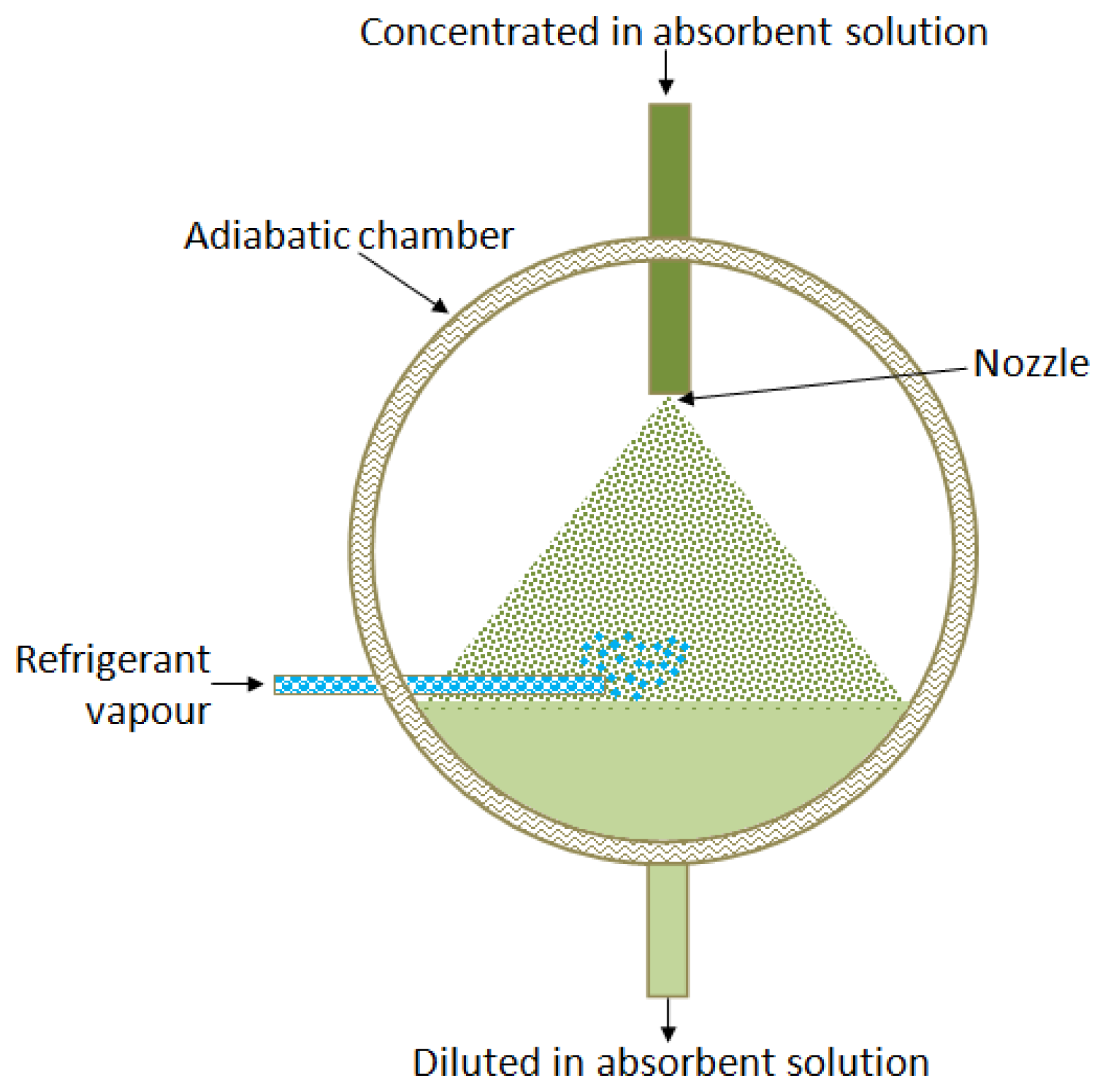
2.2. Adiabatic Absorbers
Adiabatic absorbers separate the heat and mass transfer processes. The heat transfer occurs in an external conventional single-phase heat exchanger, which allows reducing its size and cost, as a commercial model can be used. Usually mass transfer limits the absorption rate, being the liquid molecular diffusion the factor that controls the absorption process [28,29]. Figure 3 shows a schematic diagram of an adiabatic absorber.
Zacarías et al. [30] reported the performance of a fog jet nozzle adiabatic absorber operated with ammonia-lithium nitrate mixture. The fog jet nozzle used in this study was the model ¾-7G-SS 1, made by Spraying Systems Co™ (Wheaton, IL, USA), which is based on a diverging layout of seven solid cone injectors. The range of absorption mass flux were between 0.004 and 0.010 kg m−2·s−1 and for these experimental conditions, the mass transfer coefficients were from 1.70 × 10⁻⁴ m·s−1 to 4.70 × 10⁻⁴ m·s−1 Authors purpose correlations for mass transfer coefficient in function of dimensionless Sherwood and Reynolds numbers. Gutiérrez-Ureta et al. [31] evaluated two adiabatic absorber configurations: droplets and liquid sheets integrated into an absorption cooling machine operated with water/lithium bromide mixture. The authors' analysis suggested than the absorber configuration based on fan sheets showed better performance parameters than the droplets configuration. A significant reduction in the absorber size (up to 50%) is possible. Zacarías et al. [32] carried out an experimental evaluation of the adiabatic absorption of ammonia vapour into ammonia/lithium nitrate solution using a flat fan nozzle; the model was ¼-H-VV-SS 65 06 made by Spraying Systems Co™, with the following characteristics: equivalent hole diameter 1.5 mm, atomization angle 54° and capacity from 1.7 L/min to 2.4 L/min. The mass transfer coefficients achieved were from 3.40 × 10⁻⁴ m·s−1 to 1.01 × 10⁻³ m·s−1. Atomization of liquid requires a quantity of energy, due to which Palacios et al. [33] proposed and carried out an evaluation of mass absorption in LiBr flat-fan sheets adiabatic absorber integrated into chamber absorption. The mass transfer coefficient values were found to be close to 3.0 × 10⁻⁴ m·s−1. In absorption chambers 100 mm long, 0.8 g·s−1 of vapour were absorbed per chamber. The authors concluded that flat-fan sheet configurations showed better performance than falling film and spray absorbers.
An extensive experimental study of adiabatic spray absorbers was carried out by Warnakulasuriya and Worek [34], who evaluated the performance of different nozzles in an adiabatic absorber chamber using water/LiBr mixture. In this study the authors reported the absorption ratio, defined as the weight of water vapor absorbed per unit weight of circulated salt solution, and the values achieved were 0.0020 to 0.0065 (dimensionless) calculated as a function of absorption chamber pressure. Different nozzles used in adiabatic absorbers allow to increase significantly the absorption surface area by atomization of liquid working mixtures (such as occurs with fog-jet nozzles) or can improve the mixing of refrigerant vapour with the working mixture (such as occurs with flat-sheet or conical-sheet nozzles). Flat and conical-sheets nozzles configurations reduced the mechanical energy required by the liquid atomization, but also reduced the surface area.
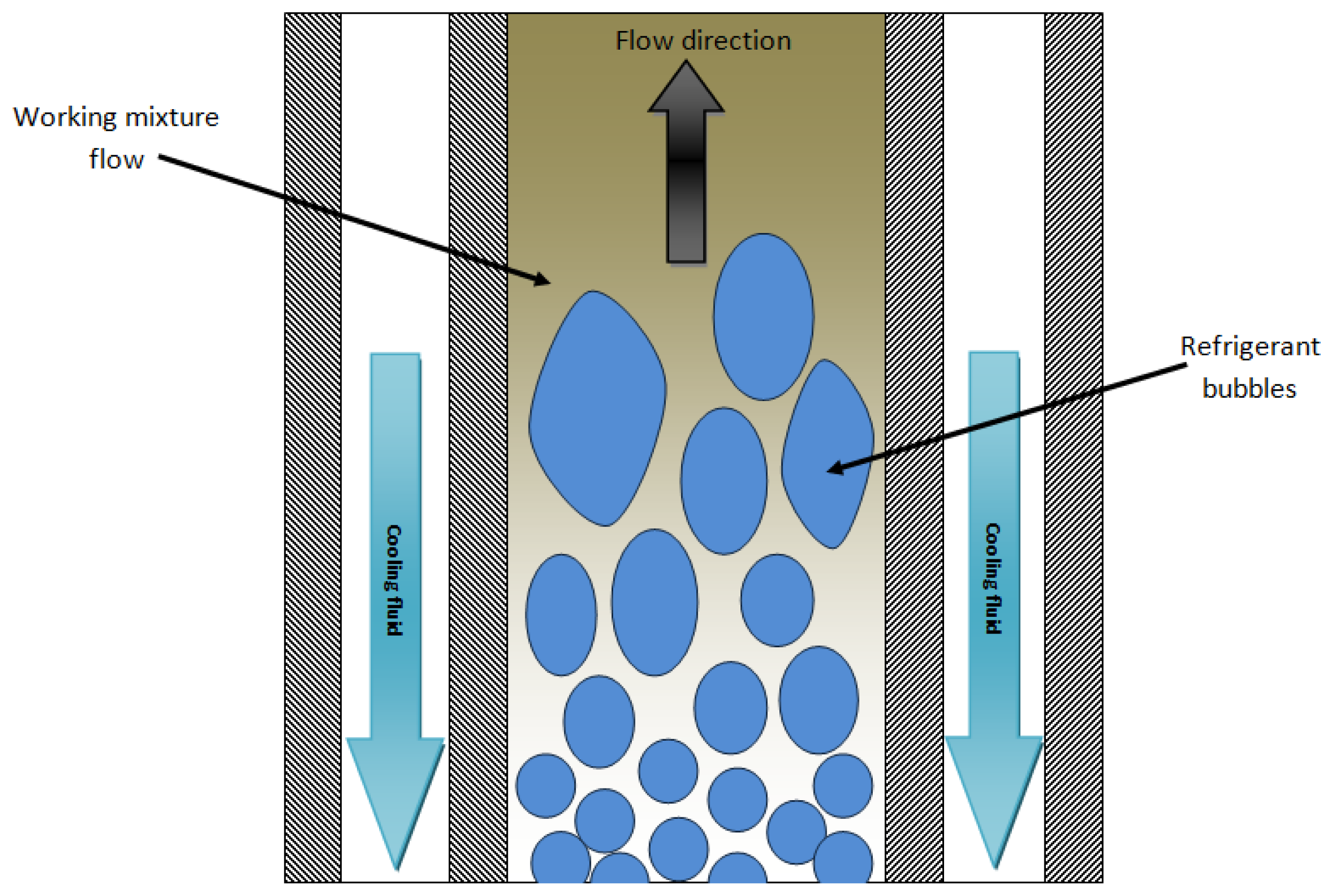
2.3. Bubble Absorbers
Bubble type absorbers provide better heat and mass transfer coefficients, and also good wettability and mixing between the liquid and the vapor [35]. Bubble absorption is in general more efficient than falling-film absorption, especially for low solution flow rates. This fact is explained by the low wetted area in falling film flow under such regimes. These low solution flow rates are more characteristic of low capacity absorbers, therefore, the bubble flow is more suitable in such applications [36]. Figure 4 shows the bubble absorber configuration.
Oronel et al. [37] evaluated the heat and mass transfer coefficients in a bubble plate absorber operated with NH3/LiNO3 and NH3/(LiNO3-H2O) mixtures. The absorber used was a corrugated plate heat exchanger with Chevron-L type corrugation (30° from the plate vertical axis) with 0.1 m2 heat transfer area. The heat exchanger was formed by four plates with three channels. The upflow of solution in the central channel was cooled by the downflow of water in the two external channels. The mass absorption flux and the solution heat transfer coefficient achieved with the ternary mixture were around 1.3–1.6 and 1.4 times higher, respectively, than those of the binary mixture under similar operating conditions. Suresh and Mani [38] reported the heat and mass transfer studies on a compact bubble absorber operated with R134a-DMF mixture for an absorption refrigeration machine. In this experimental absorber, the mass transfer and heat transfer phenomenon were separated: the working fluid vapour flowed through an inner tube with nozzles and the bubbles mixed with absorbent solution in an annular section, such as an adiabatic absorber. After that, the heat transfer was carried out in a plate heat exchanger with 22 effective plates and 0.6 m2 for heat transfer. The average mass transfer effectiveness was 0.8 associated with a heat transfer effectiveness value of about 0.85. A novel bubble absorber was described by Cardenas and Narayanan [39]. This absorber has a constrained thin-film of ammonia/water solution, and ammonia vapour bubbles are injected from a porous wall. Two absorber channel geometries, each of 600 mm nominal depth, were reported: (1) a smooth-wall channel; and (2) a stepped-wall channel that has 2-mm deep trenches across the width of a channel wall. The overall heat transfer coefficient and the mass transfer conductance for the first geometry were 800 W·m−2·K−1 to 2200 W·m−2·K−1 and 0.03 kg·s−1·m−2 to 0.16 kg·s−1·m−2 respectively. For the second geometry these parameters were 1000–1800 W·m−2·K−1 and 0.03–0.24 kg·s−1·m−2, respectively, calculated for different mass flow rates of working fluid vapour and absorber solution with different coolant inlet temperatures. The authors reported the heat transfer effectiveness for a smooth-wall channel absorber of 0.93 and of 0.97 (dimensionless) for a stepped-wall channel absorber. Cerezo et al. [40] reported an experimental study of an ammonia-water bubble absorber. The absorber used in the experimental set-up was a corrugated plate heat exchanger with three channels of 0.1 m2 effective surface area in the central channel. The mass absorption flux was in the 0.0025–0.0063 kg·m−2·s−1 range, the solution heat transfer coefficient varied between 2.7 kW·m−2·K−1 and 5.4 kW·m−2·K−1 and the mass transfer coefficient was between 0.001 m·s−1 and 0.002 m·s−1. In bubble absorbers, is possible to use simple heat exchanger geometries, such as double-pipe or commercial plate heat exchangers to allow improved mixing of refrigerant vapour with liquid working mixture due to the plate corrugations. However, in this absorber type there is a risk of evaporator contamination by a working mixture, which is a serious problem because the absorption process can be hindered due to an increase of the boiling temperature of contaminated refrigerant, and evaporator cleanup will then be necessary.
2.4. Membrane Absorbers
The membrane absorber is a novel absorber design proposed by Ali and Schwerdt [41] for cooling absorption systems operated with water/LiBr mixtures. The authors indicated that the membrane characteristics for this application are as follows: high permeability to water vapor, hydrophobic to the aqueous solution with high liquid entry pressure to avoid wettability of the membrane pores and no capillary condensation of water vapor to avoid blocking of the pores. The experimental absorber consisted a cell with PTFE hydrophobic membrane with a net contact membrane area of 46.57 cm2 and 4 mm in depth. The authors reported that to achieve a higher water vapor flux, the membrane pore sizes should range from 0.45 mm to 1.0 mm, while having a porosity of up to 80%. After this experimental study, Ali [42] proposed a design for a compact plates-and-frames absorber with a hydrophobic microporous membrane contactor at the aqueous solution-water vapor interface. The main design parameters obtained were a membrane contactor area of 6.06 m2, a ratio of the mass transfer area to absorber net volume of 130.1 (m2/m3), and ratio of mass transfer membrane area to required for heat transfer was 1.162, respectively. Isfahani and Moghaddam [43] reported an experimental absorber based in superhydrophobic nanofibrous structures. It has 77.14 cm2 of active heat and mass transfer area. The membrane used in this experimental report had a nominal pore size of 1 μm and was 80% porous. The solution microchannels were 160 and 100 μm deep, 1 mm wide and 38 mm long. The water vapor generated in the evaporator flows through the membrane and gets absorbed by the strong LiBr solution. The range of absorption mass flux was 0.0035–0.0075 kg·m−2·s−1.
In membrane absorbers, refrigerant vapour pressure has a significant influence on the performance; also the pressure and absorption mass flux increases their values, similar to an adiabatic absorber. Nominal pore size also has an impact on the absorber performance. Small sizes can to cause condensation of refrigerant vapour due pressure increase by flow space reduction.
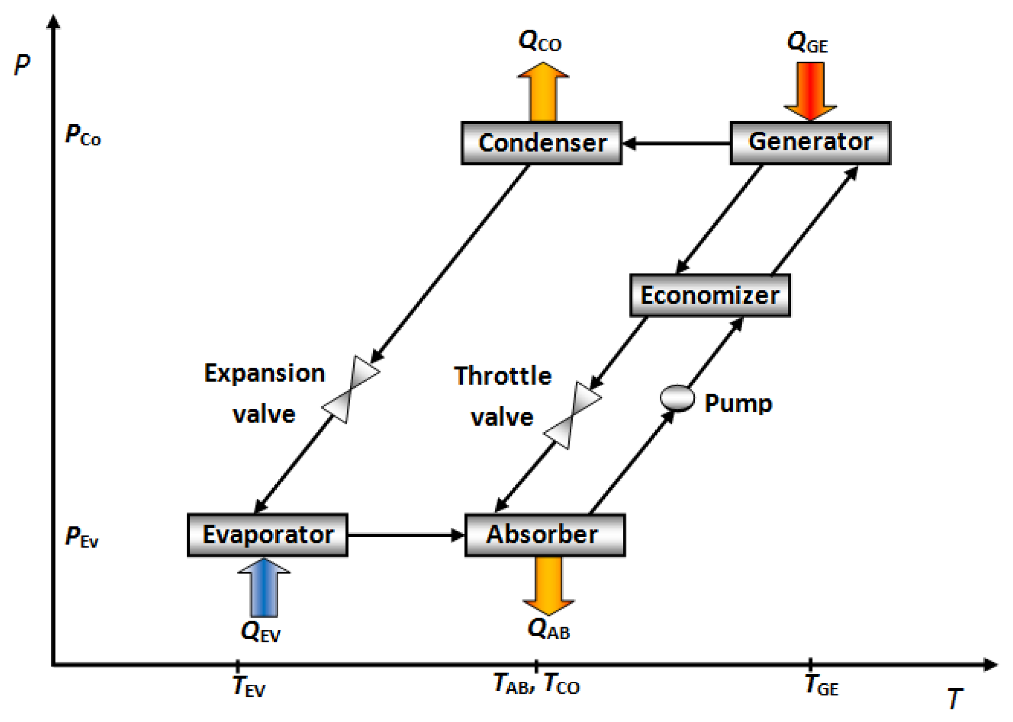
3. Absorbers in Heating Absorption Cycles
Heating absorption cycles, such as Absorption Heat Transformers (AHTs), operate in a cycle that is the reverse of the cooling absorption cycle. AHTs have received considerable attention in terms of the utilization of industrial waste heat and numerous other devices for low-level heat resources, such as solar energy and geothermal heat, because of their specific capability to increase the temperature of heat sources from a low to a high useful level [44,45].
The AHT basically consists of an evaporator, a condenser, a generator, an absorber and a solution heat exchanger. Figure 5 shows a schematic diagram of this absorption cycle. A constant quantity of waste heat (QGE) is added at a relatively low temperature (TGE) to the generator vaporizes part of the working fluid, from the diluted salt solution, containing a low concentration of absorbent. The vaporized working fluid flows to the condenser, delivering an amount of heat (QCO) at close ambient temperature (TCO). The liquid leaving the condenser is pumped, driven by a small energy power source, to the evaporator at a higher–pressure zone. The working fluid is then evaporated by using a second quantity of heat waste (QEV), which is added to the evaporator at an intermediate temperature (TEV). At same time, the vaporized working fluid goes to the absorber, inside of which, it is absorbed by the concentrated absorbent salt solution; this stream comes from the generator. The absorption process delivers useful heat (QAB) at a higher temperature (TAB). Finally, the diluted salt solution returns to the generator, to preheat the concentrated salt solution in a heat exchanger, called “economizer”, before restarting the cycle again [46]. The useful heat produced by an AHT can be used for heat energy revalorization in industrial processes [47] and water purification [48–50].
In this cycle the absorber works at the highest temperature of all components, therefore, the highest irreversibilities also occur in the absorber [50–52]. There are more experimental reports about absorption cooling systems than heating absorption systems such as absorption heat transformer, however, the absorber designs reported for these machines are described below.
3.1. Falling Film Absorbers
A recently falling film absorber integrated into an AHT operated with a water/lithium bromide mixture was described by Olarte-Cortés et al. [53]. This design consisted of a vertical absorber built with 18 tar-impregnated graphite disks with a surface slope of 7° in the upper and 14° in the lower part and a rough surface to improve the distribution of the working mixture.
The absorber was formed externally by a 316 L stainless steel tube joined in its upper and lower ends to two bridles coupled to two headers with screws that give the disks column rigidity and a hermetic seal (with 0.17 m in diameter and 0.56 m in length). The authors reported than the heat transfer coefficients in the absorber were calculated to range from 723 W·m−2·K−1 to 1535 W·m−2·K−1 for different mass flow rates. Rivera [54] reported the experimental evaluation of a single stage heat transformer, operated with a water/Carrol mixture. The absorber of this experimental device was made of borosilicate glass; the shell-and-coil heat exchanger had 0.29 m2 of heat exchange surface. With this absorber the highest temperature achieves was 132 °C. Genssle and Stephan [55] reported an experimental absorption heat transformer operated with trifluorethanol (TFE)/tetraethyleneglycol-dimethylether (E181) mixture. The absorber consisted of a stainless steel helical coil. The overall heat transfer coefficient was calculated between 370 W·m−2·K−1 and 430 W·m−2·K−1 and the overall mass transfer coefficient was calculated from 20 g·m−2·s−1 to 90 g·m−2·s−1.
3.2. Adiabatic Absorbers
There are no experimental reports about adiabatic absorbers in absorption heat transformers; however, some authors have carried out theoretical analyses of this kind of absorber [56,57]. Adiabatic absorbers in AHT need an increased evaporator pressure; it implies a high heat supply in the evaporator. This can be achieved by two methods: first method, increasing the temperature in the evaporator source; or second method, using advanced configurations, such as Triple or Double Stage Heat Transformer [58–62] or Double Absorption Heat Transformer [63–66], but these experimental kinds of AHTs have not been reported yet. Other authors have reported experimental AHTs [48–50,67,68], however, they didn't carry out an absorption analysis.
4. Influence of the Working Mixture on Absorber Design
The performance of an absorption cycle is critically dependent on the thermodynamic properties of the working fluid. The mixture of absorbent-refrigerant should be chemically stable, non-toxic, and non-explosive [69]. The most important thermophysical properties are: vapour pressure of the refrigerant and absorbent solution, heat of vaporization of the refrigerant, heat of solution, solubility of refrigerant in absorbent, heat capacity, viscosity, density, surface tension and thermal conductivity of the absorbent solution [70].
Besides the above, in order to reduce the entropy generation into absorber, the working mixture must be carefully selected. The entropy generation into absorber, in general form, is as follows [71]:
There is not a “general best” working mixture, but carrying out an analysis of the working mixture thermodynamic properties is important to improve the absorber performance. Therefore, the working mixture must have low heat of dilution values, but, in heating cycles, the highest values of this property are desirable to increase the absorber heat power, and consequently, the increase of COP. The absorber operating temperatures must be near to ambient temperature in order to reduce entropy generation by super heating, which is possible in cooling cycles, but in heating cycles it is not possible, because the aim of these machines is a temperature increase, therefore, the absorber operated at highest temperature of all components. The working mixture must have a high thermal conductivity for improve the heat transfer and reduce the absorber area and low viscosity values in order to reduce the entropy generation due to friction flow.
5. Conclusions
The absorber is the most important component of absorption machines, in general, its performance impacts directly in the size and energy supply of all absorption devices. Absorption cooling and heating cycles have different absorber design requirements: in absorption cooling systems, the absorber works near to ambient temperature, therefore, the mass transfer is the most important phenomenon in order to reduce the generator size and power of pumps; in the other hand, in heating absorption systems, it is important to recover the heat delivery by the exothermic reactions produced in the absorber, for this reason, the absorber heat transfer coefficient is an important parameter. A review of different experimental absorbers designs was carried out. The conclusions can be summarized as follows:
Falling film absorbers are the most common type absorber in cooling absorption machines, however, this design has a wettability problem that deteriorates the absorption performance and heat and mass transfer in this kind of absorber is greatly influenced by the fluid properties and geometry of the heat exchanger.
Adiabatic absorbers separate the processes of heat and mass transfer; for the heat evacuation a high thermal efficiency heat exchanger (such as Plate Heat Exchangers) can be used, which allows reducing the size and cost of machines, however, the operating pressure influences the mass transfer in the liquid layer.
Bubble type absorbers provide better heat and mass transfer coefficients and are more efficient than falling film absorption, especially for low solution flow rates, but, a risk of evaporator contamination by the working mixture exists.
Absorption cooling systems have more absorber design variety, but these designs can be adapted in heating absorption cycles in order to increase the performance of these absorption machines.
The working mixture is an important absorber design parameter. In order to reduce the entropy generation, improve the heat and mass transfer area and increase the performances of absorption machine, a thermodynamics properties analysis must be carry out.
Acknowledgments
The authors appreciate the partial support of “167434 Basic Science”, “Red temática Fuentes de Energía—CONACyT” and FECES 2012 “Mejora de la Capacidad y Competitividad Académica e Impulso a la Innovación Educativa” projects.
Conflicts of Interest
The authors declare no conflict of interest.
References
- Chan, C.W.; Ling-Chin, J.; Roskilly, A.P. Reprint of “A review of chemical heat pumps, thermodynamic cycles and thermal energy storage technologies for low grade heat utilisation”. Appl. Therm. Eng. 2013, 53, 160–176. [Google Scholar]
- Jonsson, M.E.; Granryd, E. Multipurpose Heat Pump for Domestic Applications. Proceedings of the IIF-IIR-Commission E2 & B2, Linz, Austria, 28 September–1 October 1997; pp. 224–232.
- Garimella, S. Innovations in energy efficient and environmentally friendly space-conditioning systems. Energy 2003, 28, 1593–1614. [Google Scholar]
- Stolk, A.L.; Waszenaar, R.H. Heat and Mass Transfer Phenomena in an Absorber with Drop-Wise Falling Film on Horizontal Tubes. Proceedings of the International Refrigeration and Air Conditioning Conference, West Lafayette, IN, USA, 4–7 August 1986; pp. 250–256.
- Xie, G.; Sheng, G.; Bansal, P.K.; Li, G. Absorber performance of a water/lithium-bromide absorption chiller. Appl. Therm. Eng. 2008, 28, 1557–1562. [Google Scholar]
- Aphornratana, S.; Eames, I.W. Thermodynamic analysis of absorption refrigeration cycles using the second law of thermodynamics method. Int. J. Refrig. 1995, 18, 244–252. [Google Scholar]
- Talbi, M.M.; Agnew, B. Exergy analysis: An absorption refrigerator using lithium bromide and water as the working fluids. Appl. Therm. Eng. 2000, 20, 619–630. [Google Scholar]
- Sencan, A.; Yakut, K.A.; Kalogirou, S.A. Exergy analysis of lithium bromide/water absorption systems. Renew. Energy 2005, 30, 645–657. [Google Scholar]
- Kilic, M.; Kaynakli, O. Second law-based thermodynamic analysis of water-lithium bromide absorption refrigeration system. Energy 2007, 32, 1505–1512. [Google Scholar]
- George, J.M.; Murthy, S.S. Influence of absorber effectiveness on performance of vapour absorption heat transformers. Int. J. Energy Res. 1989, 13, 629–638. [Google Scholar]
- Ng, K.C.; Tu, K.; Chua, H.T.; Gordon, J.M.; Kashiwagi, T.; Akisawa, A.; Saha, B.B. Thermodynamic analysis of absorption chillers: Internal dissipation and process average temperature. Appl. Therm. Eng. 1998, 18, 671–682. [Google Scholar]
- Ying, H.; Qu, M.; Archer, D.H. Model based experimental performance analysis of a microscale LiBr-H2O steam-driven double-effect absorption Chiller. Appl. Therm. Eng. 2010, 30, 1741–1750. [Google Scholar]
- Chua, H.T.; Toh, H.K.; Malek, A.; Ng, K.C.; Srinivasan, K. A general thermodynamic framework for understanding the behaviour of absorption chillers. Int. J. Refrig. 2000, 23, 491–507. [Google Scholar]
- Ventas, R.; Vereda, C.; Lecuona, A.; Venegas, M.; del Carmen Rodríguez–Hidalgo, M. Effect of the NH3–LiNO3 concentration and pressure in a fog-jet spray adiabatic absorber. Appl. Therm. Eng. 2012, 37, 430–437. [Google Scholar]
- Kim, J.K.; Park, C.W.; Kang, Y.T. The effect of micro-scale surface treatment on heat and mass transfer performance for a falling film H2O/LiBr absorber. Int. J. Refrig. 2003, 26, 575–585. [Google Scholar]
- Harikrishnan, L.; Maiya, M.P.; Tiwari, S. Investigations on heat and mass transfer characteristics of falling film horizontal tubular absorber. Int. J. Heat Mass Transf. 2011, 54, 2609–2617. [Google Scholar]
- Lee, S.; Bohra, L.K.; Garimella, S.; Nagavarapu, A.K. Measurement of absorption rates in horizontal-tube falling-film ammonia-water absorbers. Int. J. Refrig. 2012, 35, 613–632. [Google Scholar]
- Bredow, D.; Jain, P.; Wohlfeil, A.; Ziegler, F. Heat and mass transfer characteristics of a horizontal tube absorber in a semi-commercial absorption chiller. Int. J. Refrig. 2008, 31, 1273–1281. [Google Scholar]
- Yoon, J.I.; Phan, T.T.; Moon, C.G.; Lee, H.S.; Jeong, S.K. Heat and mass transfer characteristics of a horizontal tube falling film absorber with small diameter tubes. Heat Mass Transf. 2008, 44, 437–444. [Google Scholar]
- Kyung, I.; Herold, K.E.; Kang, Y.T. Experimental verification of H2O/LiBr absorber bundle performance with smooth horizontal tubes. Int. J. Refrig. 2007, 30, 582–590. [Google Scholar]
- Yoon, J.I.; Kwon, O.K.; Bansal, P.K.; Moon, C.G.; Lee, H.S. Heat and mass transfer characteristics of a small helical absorber. Appl. Therm. Eng. 2006, 26, 186–192. [Google Scholar]
- Bourouis, M.; Vallès, M.; Medrano, M.; Coronas, A. Absorption of water vapour in the falling film of water-(LiBr + LiI + LiNO3 + LiCl) in a vertical tube at air-cooling thermal conditions. Int. J. Therm. Sci. 2005, 44, 491–498. [Google Scholar]
- Kurosawa, S.; Nagaoka, Y.; Yoshida, A.; Masato, O.; Kunugi, Y. Development of Air-Cooled Gas-Fired Absorption Water Chiller-Heater. In Working Fluids and Transport Phenomena in Advanced Absorption Heat Pumps: Final Report; IEA Heat Pump Center: Borås, Sweden, 1990; Annex 14; Volume 2, pp. 9.01–9.42. [Google Scholar]
- Kwon, K.; Jeong, S. Effect of vapor flow on the falling-film heat and mass transfer of the ammonia/water absorber. Int. J. Refrig. 2004, 27, 955–964. [Google Scholar]
- Islam, M.R.; Wijeysundera, N.E.; Ho, J.C. Performance study of a falling-film absorber with a film-inverting configuration. Int. J. Refrig. 2003, 26, 909–917. [Google Scholar]
- Yoon, J.I.; Kim, E.; Choi, K.H.; Seol, W.S. Heat transfer enhancement with a surfactant on horizontal bundle tubes of an absorber. Int. J. Heat Mass Transf. 2002, 45, 735–741. [Google Scholar]
- Miller, W.A.; Perez-Blanco, H. Vertical-Tube Aqueous LiBr Falling Film Absorption Using Advanced Surfaces. Proceedings of the International Absorption Heat Pumps Conference, New Orleans, LA, USA, 19–21 January 1994; ASME: New York, NY, USA.
- Ventas, R.; Lecuona, A.; Legrand, M.; Rodríguez-Hidalgo, M.C. On the recirculation of ammonia-lithium nitrate in adiabatic absorbers for chillers. Appl. Therm. Eng. 2010, 30, 2770–2777. [Google Scholar]
- Ryan, W.A. Water Absorption in an Adiabatic Spray of Aqueous Lithium Bromide Solution. Proceedings of the International Absorption Heat Pump Conference, New Orleans, LA, USA, 19–21 January 1994; ASME: New York, NY, USA, 1994; pp. 155–162. [Google Scholar]
- Zacarías, A.; Venegas, M.; Lecuona, A.; Ventas, R. Experimental evaluation of ammonia adiabatic absorption into ammonia–lithium nitrate solution using a fog jet nozzle. Appl. Therm. Eng. 2013, 50, 781–790. [Google Scholar]
- Gutiérrez-Urueta, G.; Rodríguez, P.; Venegas, M.; Ziegler, F.; Rodríguez-Hidalgo, M.C. Experimental performances of a LiBr-water absorption facility equipped with adiabatic absorber. Int. J. Refrig. 2011, 34, 1749–1759. [Google Scholar]
- Zacarías, A.; Venegas, M.; Ventas, R.; Lecuona, A.; Ventas, R. Experimental assessment of ammonia adiabatic absorption into ammonia–lithium nitrate solution using a flat fan nozzle. Appl. Therm. Eng. 2011, 31, 3569–3579. [Google Scholar]
- Palacios, E.; Izquierdo, M.; Marcos, J.D.; Lizarte, R. Evaluation of mass absorption in LiBr flat–fan sheets. Appl. Energy 2009, 86, 2574–2582. [Google Scholar]
- Warnakulasuriya, F.S.K.; Worek, W.M. Adiabatic water absorption properties of an aqueous absorbent at very low pressures in a spray absorber. Int. J. Heat Mass Transf. 2006, 49, 1592–1602. [Google Scholar]
- Tae Kang, Y.; Akisawa, A.; Kashiwagi, T. Analytical investigation of two different absorption modes: Falling film and bubble types. Int. J. Refrig. 2000, 23, 430–443. [Google Scholar]
- Castro, J.; Oliet, C.; Rodríguez, I.; Oliva, A. Comparison of the performance of falling film and bubble absorbers for air-cooled absorption systems. Int. J. Therm. Sci. 2009, 48, 1355–1366. [Google Scholar]
- Oronel, C.; Amaris, C.; Bourouis, M.; Vallés, M. Heat and mass transfer in a bubble plate absorber with NH3/LiNO3 and NH3/(LiNO3-H2O) mixtures. Int. J. Therm. Sci. 2013, 63, 105–114. [Google Scholar]
- Suresh, M.; Mani, A. Heat and mass transfer studies on a compact bubble absorber in R134a-DMF solution based vapour absorption refrigeration system. Int. J. Refrig. 2013, 36, 1004–1014. [Google Scholar]
- Cardenas, R.; Narayanan, V. Heat and mass transfer characteristics of a constrained thin-film ammonia-water bubble absorber. Int. J. Refrig. 2011, 34, 113–128. [Google Scholar]
- Cerezo, J.; Bourouis, M.; Valles, M.; Coronas, A.; Best, R. Experimental study of an ammonia–water bubble absorber using a plate heat exchanger for absorption refrigeration machines. Appl. Therm. Eng. 2009, 29, 1005–1011. [Google Scholar]
- Ali, A.H.H.; Schwerdt, P. Characteristics of the membrane utilized in a compact absorber for lithium bromide–water absorption chillers. Int. J. Refrig. 2009, 32, 1886–1896. [Google Scholar]
- Ali, A.H.H. Design of a compact absorber with a hydrophobic membrane contactor at the liquid–vapor interface for lithium bromide–water absorption chillers. Appl. Energy 2010, 87, 1112–1121. [Google Scholar]
- Isfahani, R.N.; Moghaddam, S. Absorption characteristics of lithium bromide (LiBr) solution constrained by superhydrophobic nanofibrous structures. Int. J. Heat Mass Transf. 2013, 63, 82–90. [Google Scholar]
- Guo, P.J.; Sui, J.; Han, W.; Zheng, J.J.; Jin, H.G. Energy and exergy analyses on the off-design performance of an absorption heat transformer. Appl. Therm. Eng. 2012, 48, 506–514. [Google Scholar]
- Horuz, I.; Kurt, B. Absorption heat transformers and an industrial application. Renew. Energy. 2010, 35, 2175–2181. [Google Scholar]
- Ibarra-Bahena, J.; Romero, R.J.; Velazquez-Avelar, L.; Valdez-Morales, C.V.; Galindo-Luna, Y.R. Evaluation of the thermodynamic effectiveness of a plate heat exchanger integrated into an experimental single stage heat transformer operating with Water/Carrol mixture. Exp. Therm. Fluid Sci. 2013, 51, 257–263. [Google Scholar]
- Ma, X.; Chen, J.; Li, S.; Sha, Q.; Liang, A.; Li, W.; Zhang, J.; Zheng, G.; Feng, Z. Application of absorption heat transformer to recover waste heat from a synthetic rubber plant. Appl. Therm. Eng. 2003, 23, 797–806. [Google Scholar]
- Sekar, S.; Saravanan, R. Experimental studies on absorption heat transformer coupled distillation system. Desalination 2011, 274, 292–301. [Google Scholar]
- Huicochea, A.; Siqueiros, J.; Romero, R.J. Portable water purification system integrated to a heat transformer. Desalination 2004, 165, 385–391. [Google Scholar]
- Rivera, W.; Huicochea, A.; Martínez, H.; Siqueiros, J.; Juárez, D.; Cadenas, E. Exergy analysis of an experimental heat transformer for water purification. Energy 2011, 36, 320–327. [Google Scholar]
- Rivera, W.; Martínez, H.; Cerezo, J.; Romero, R.J.; Cardoso, M.J. Exergy analysis of an experimental single-stage heat transformer operating with single water/lithium bromide and using additives (1-octanol and 2-ethyl-1- hexanol). Appl. Therm. Eng. 2011, 31, 3526–3532. [Google Scholar]
- Sözen, A. Effect of irreversibilities on performance of an absorption heat transformer used to increase solar pond's temperature. Renew. Energy 2003, 29, 501–515. [Google Scholar]
- Olarte–Cortés, J.; Torres-Merino, J.; Siqueiros, J. Experimental study of a graphite disks absorber couple to a heat transformer. Exp. Therm. Fluid Sci. 2013, 46, 29–36. [Google Scholar]
- Rivera, W. Experimental evaluation of a single–stage heat transformer used to increase solar pond's temperature. Sol. Energy 2000, 69, 369–376. [Google Scholar]
- Genssle, A.; Stephan, K. Analysis of the process characteristics of an absorption heat transformer with compact heat exchangers and the mixture TFE–E181. Int. J. Therm. Sci. 2000, 39, 30–38. [Google Scholar]
- Sözen, A.; Arcaklioglu, E.; Özalp, M.; Yücesu, S. Performance parameters of an ejector-absorption heat transformer. Appl. Energy 2005, 80, 273–289. [Google Scholar]
- Shi, L.; Yin, J.; Wang, X.; Zhu, M.S. Study on a new ejection-absorption heat transformer. Appl. Energy 2011, 68, 161–171. [Google Scholar]
- Donnellan, P.; Byrne, E.; Oliveira, J.; Cronin, K. First and second law multidimensional analysis of a triple absorption heat transformer (TAHT). Appl. Energy 2014, 113, 141–151. [Google Scholar]
- Donnellan, P.; Byrne, E.; Cronin, K. Internal energy and exergy in high temperature application absorption heat transformers. Appl. Therm. Eng. 2013, 56, 1–10. [Google Scholar]
- Gomri, R. Thermal seawater desalination: Possibilities of using single effect and double effect absorption heat transformer systems. Desalination 2010, 253, 112–118. [Google Scholar]
- Zhao, Z.C.; Zhang, X.D.; Ma, X.H. Thermodynamic performance of a double–effect absorption heat–transformer using TFE/E181 as the working fluid. Appl. Energy 2005, 82, 107–116. [Google Scholar]
- Reyes, R.M.B.; Gómez, V.M.A.; García-Gutiérrez, A. Performance modelling of single and double absorption heat transformers. Curr. Appl. Phys. 2010, 10, S244–S248. [Google Scholar]
- Zhao, Z.C.; Ma, Y.P.; Chen, J.B. Thermodynamic performance of a new type of double absorption heat transformer. Appl. Therm. Eng. 2003, 23, 2407–2414. [Google Scholar]
- Rivera, W.; Cerezo, J.; Rivero, R.; Cervantes, J.; Best, R. Single stage and double absorption heat transformers used to recover energy in a distillation column of butane and pentane. Int. J. Energy Res. 2003, 27, 1279–1292. [Google Scholar]
- Horuz, I.; Kurt, B. Single stage and double absorption heat transformers in an industrial application. Int. J. Energy Res. 2009, 33, 787–798. [Google Scholar]
- Barragán R., R.M.; Arellano G., V.M.; Heard, C.L. Performance study of a double-absorption water/calcium chloride heat. Int. J. Energy Res. 1998, 22, 791–803. [Google Scholar]
- Rivera, W.; Cerezo, J. Experimental study of the use of additives in the performance of a single-stage heat transformer operating with water–lithium bromide. Int. J. Energy Res. 2005, 29, 121–130. [Google Scholar]
- Rivera, W.; Romero, R.J.; Cardoso, M.J.; Aguillón, J.; Best, R. Theoretical and experimental comparison of the performance of a single-stage heat transformer operating with water/lithium bromide and water/Carrol™. Int. J. Energy Res. 2002, 26, 747–762. [Google Scholar]
- Perez, B.H. Absorption heat pump performance for different types of solution. Int. J. Refrig. 1984, 7, 115–122. [Google Scholar]
- Saravanan, R.; Maiya, M.P. Influence of thermodynamic and thermophysical properties of water-based working fluids for bubble pump operated vapour absorption refrigerator. Energy Convers. Manag. 1999, 40, 845–860. [Google Scholar]
- Myat, A.; Thu, K.; Kim, Y.D.; Chakraborty, A.; Chun, W.G.; Ng, K.C. A second law analysis and entropy generation minimization of an absorption chiller. Appl. Therm. Eng. 2011, 31, 2405–2413. [Google Scholar]


© 2014 by the authors; licensee MDPI, Basel, Switzerland. This article is an open access article distributed under the terms and conditions of the Creative Commons Attribution license ( http://creativecommons.org/licenses/by/3.0/).
Share and Cite
Ibarra-Bahena, J.; Romero, R.J. Performance of Different Experimental Absorber Designs in Absorption Heat Pump Cycle Technologies: A Review. Energies 2014, 7, 751-766. https://doi.org/10.3390/en7020751
Ibarra-Bahena J, Romero RJ. Performance of Different Experimental Absorber Designs in Absorption Heat Pump Cycle Technologies: A Review. Energies. 2014; 7(2):751-766. https://doi.org/10.3390/en7020751
Chicago/Turabian StyleIbarra-Bahena, Jonathan, and Rosenberg J. Romero. 2014. "Performance of Different Experimental Absorber Designs in Absorption Heat Pump Cycle Technologies: A Review" Energies 7, no. 2: 751-766. https://doi.org/10.3390/en7020751
APA StyleIbarra-Bahena, J., & Romero, R. J. (2014). Performance of Different Experimental Absorber Designs in Absorption Heat Pump Cycle Technologies: A Review. Energies, 7(2), 751-766. https://doi.org/10.3390/en7020751