1. Introduction
High temperature fuel cells have shown significant potential as a viable solution for power production. The Solid Oxide Fuel Cells (SOFC) system is the most mature of the many options. It operates in the range of 750–1000 °C, which allows it to combine with other conventional thermal cycles to further enhance the thermal efficiency [
1]. The hybrid SOFC system is considered to be a key technology in achieving the goals of the future on account of the many advantages it offers over other systems.
Firstly, SOFCs do not contain any moving parts. Noise and vibrations during operation are practically non-existent, making it possible to install the systems in urban areas. The lack of mechanical parts also assures high reliability and low maintenance costs. Secondly, SOFCs can operate on a variety of fuels and are more resistant to electrode poisoning. They can tolerate sulphur compounds at concentrations higher than other types of fuel cells [
2]. In addition, unlike most fuel cells, CO can be used as a fuel in SOFC. Due to the abovementioned advantages, SOFCs are considered a strong candidate for hybrid systems or integration into currently deployed technologies. On the other hand, polymer electrolyte fuel cells also possess desirable properties in low temperature domains. Due to their low temperature operation, no internal reforming can take place and only pure hydrogen can be used as a fuel.
SOFC-based hybrid power plants have been proposed by researchers in extensive studies on integration of SOFCs in gas turbine (GT) and steam turbine (ST) power plants [
3,
4,
5], along with a few on SOFC-Stirling hybrid systems [
6,
7], whereas studies on prospects of combining SOFC with a Polymer Electrolyte Fuel Cell (PEFC) are relatively limited [
8,
9,
10,
11]. Although, SOFC-GT and SOFC-ST power plants display high efficiencies when compared to conventional combined cycles, their operations are limited to large-scale plants only. Combined SOFC–PEFC plants offer a viable potential for small-scale Combined Heat and Power (CHP) generation units due to the fact that they have rapid start-up times. However, the capital cost of SOFCs and PEFCs turns out to be the major obstacle in commercialization of these plants. This study is an effort to investigate the feasibility of a small-scale SOFC-PEFC power plant.
Hybrid systems that comprise a SOFC combined with a PEFC have been described in the literature. In these systems, the internal reforming ability of the SOFC is utilized by the PEFC to produce hydrogen. The heat released from electrochemical reactions in the SOFC is consumed in the reforming process. The exhaust stream is directed to the shift reactors, where the CO reacts with H
2O to produce CO
2 and H
2. The remaining traces of CO are removed by selective catalytic oxidation. According to [
11], overall conversion efficiency was found to be around 10% higher than that of a standalone SOFC system.
SOFC-PEFC systems that are connected in series are reported in [
12]. Using this configuration, the gas mixture fed to the cathode of the SOFC contains some water. The efficiency of the SOFC–PEFC combination as predicted by simulations is about 60% [
13]. In studies conducted by Dick
et al. [
8], it is established that the efficiency of SOFC–PEFC decreases with increasing operating pressures. Yokoo
et al. [
13,
14] also presented a parallel fuel feeding configuration in which the reformed gas was separated into two flow streams for the SOFC and the PEFC. In this parallel configuration, the PEFC is fuelled from the reformer directly (unlike the serial configuration which uses depleted fuel from the SOFC anode). According to these studies, a 5% efficiency improvement was obtained using natural gas as fuel with a parallel SOFC-PEFC system, as compared with the stand-alone SOFC.
Most of the studies on combined SOFC-PEFC systems have either highlighted the use of a combined reformer for both the SOFC and PEFC, or elaborated the use of exhaust heat from the SOFC to produce hydrogen. These systems are somewhat complex and heat management poses a considerable threat to stable plant operations. However, in the present study a simplified system is proposed in which hydrogen from the SOFC off-gas is extracted by a purifying membrane, eliminating the use of several complex reactors. Additionally, this system can handle different fuels with little or no modification. It should also be noted that the system presented here was studied thermodynamically and the objective of this study was not to present or discuss associated costs.
2. Methodology
The results of this paper are obtained using the Dynamic Network Analysis (DNA) simulation tool [
15], which is a tool for energy system analysis. It is the latest result of on-going development at the Department of Mechanical Engineering, Technical University of Denmark, which began with a Master’s Thesis work in 1989. Since then the program has been developed to be generally applicable while providing unique features, and hence supplementing other simulation programs.
In DNA, the physical model is formulated by connecting the relevant component models through nodes and by including operating conditions for the complete system. The physical model is converted into a set of mathematical equations to be solved numerically. The mathematical equations include mass and energy balances for all components and nodes as well as relations for thermodynamic properties of the fluids involved. During the development of DNA, the four key terms of portability, robustness, efficiency, and flexibility were kept in mind as the important features for making it a generally applicable tool for energy system studies. The program is written in FORTRAN. Over the years a library with different fuels such as NG, methanol, ethanol, dimethyl ether (DME), ammonia, etc., and their thermodynamic properties has been implemented.
2.1. Modeling of SOFC Stacks
The SOFC model developed in this investigation is based on the planar type developed by DTU-Risø and TOPSØE Fuel Cell (TOFC). The model was calibrated in the 650 °C to 800 °C (operating temperature) range against experimental data as described in [
5,
16], but to clarify how it is implemented in the in-house program, it is briefly explained here. The operational voltage (
EFC) was found to be:
where
ENernst, Δ
Eact, Δ
Eohm, Δ
Econc and Δ
Eoffset are the Nernst ideal reversible voltage (open voltage circuit), activation polarization, ohmic polarization, concentration polarization and the offset polarization, respectively.
The offset polarization is neglected and the Nernst reversible voltage is given by [
17]:
where R, F and ne are the universal gas constant, Faraday constant and
ne is the number of electrons transferred in the cell reaction, respectively. The partial pressures were assumed to be the average between the inlet and outlet weighted by molar fraction (
y) for anode and cathode separately as:
Thus the effect of partial pressures on the Nernst equation is neglected. The change in standard Gibbs free energy (Δ
ḡf0) is and the number of electrons transferred for each molecule of fuel (
ne = 2) and calculated by:
The activation polarization was evaluated from the Butler–Volmer equation [
18] by isolating it from other polarizations to determine the charge transfer coefficients and exchange current density from the experiment by the curve fitting technique:
where
id is the current density.
The ohmic polarization depends on the electrical conductivity of the electrodes as well as the ionic conductivity of the electrolyte and was expressed based on anode thickness, electrolyte thickness, cathode thickness and current density [
19]:
where
tan = 600 μm,
tel = 50 μm and
tca = 10 μm are the anode thickness, electrolyte thickness and cathode thickness, respectively, and σ
an, σ
el and σ
ca are the conductivities of the anode, electrolyte and cathode, respectively.
The concentration polarization is dominant at high current densities for anode-supported SOFCs, wherein insufficient amounts of reactants are transported to the electrodes and the voltage is then reduced significantly [
20]. It was modeled as a function of the diffusion coefficient, anode limiting current and current density. The anode limiting current was modeled as function of anode porosity, anode tortuosity and a binary diffusion coefficient. Both the diffusion coefficient and the binary diffusion coefficient were calibrated against experimental data:
where
B is the diffusion coefficient, which was determined using a calibration technique (see [
16] for details).
Finally the current density is directly proportional to the amount of reacting hydrogen and the cell area, according to Faraday’s law. The fuel composition leaving the anode was calculated by the Gibbs minimization method, as described in [
21]. The power production from the SOFC (
PSOFC) depends on the amount of chemical energy fed to the anode, the reversible efficiency (ƞ
rev), the voltage efficiency (ƞ
v) and the fuel utilization factor (
UF). It is defined in mathematical form as:
where
ṅ was the molar reaction rate (molar flow),
UF was a set value while the reversible efficiency is the maximum possible efficiency defined as the relationship between the maximum electrical energy available (change in Gibbs free energy) and the fuels LHV (lower heating value) as follows:
Other alternative SOFC modelling can also be found in the literature [
22,
23,
24]. For example, [
22] presents SOFC modeling with parameter identification by means of impedance spectroscopy. In [
23] recent developments of 3D coupled multi physics from the Julich research centre can be found.
2.2. Modeling of PEFC
The PEFC model applied in this investigation is based on the planar type developed by Ballard and therefore, the model was calibrated against experimental data available from this manufacturer [
25]. The details can be found in the study of Hosseinzadeh and Rokni [
26].
The average cell voltage of the fuel cell was defined by an analytical expression defined in Equation (1). To evaluate the activation loss, the well-known Butler-Volmer equation was used to derive the relationship between activation loss and current density. The cell total activation loss is the sum of anode and cathode contributions as:
wherein
i0,cathode = 10
−5i0,anode and
i0,cathode was calibrated against experimental data and found to be:
where R,
T and F were the universal gas constant, cell temperature and Faradays constant respectively.
The ohmic resistance was calibrated against the experimental data and found to be given by:
where
i was the current density (set value) and λ
av was the average water content in anode and cathode sides. It was calculated based on water vapour partial pressure (
pw) and saturated partial pressure of water (
psat) as:
The water content in the polymer electrolyte plays a significant role in stack lifetime and the ionic resistance of the membrane. Low humidification in the membrane causes a rapid increase in ionic resistance and high humidification will produce too much liquid water, which will overflow into the reactant channels and fill the pores in the electrodes. In order to have high ionic conductivity in the membrane it should be fully hydrated. Hydration could be achieved by the humidification of the gases, or by designing the fuel cell in a way that the water produced is allowed to hydrate the membrane [
27]. Such water crossover was also applied here.
There exist alternative PEM modelling options in the literature. Analytical modelling of PEM can, for example, be found in [
28], while [
29] presents a thermo-mechanical study of PEM fuel cells and a comprehensive review on PEM water electrolysis is provided in [
30].
2.4. Modeling of Other Components
The pump power consumption was calculated as:
where ṁ,
p,
ν and
ƞ were the mass flow, pressure, specific volume (m
3/kg) and efficiency of the pump, respectively. The pump efficiency and outlet pressure were defined as shown below. The power consumption for compressors were modeled based on the definition of isentropic and mechanical efficiencies (given values) as:
where and
hSin was the enthalpy when the entropy kept constant as for the inlet.
In modeling a heat exchanger, it was assumed that all energy from one side is transferred to the other side if heat losses were neglected, (which was also the case in this study). Depending on the type of the heat exchanger both the Logarithmic Mean Temperature Difference (LMTD) and effectiveness-Number of Transferred Unit (ε-NTU) methods were used.
3. Plant Configurations
The proposed combined power system is constituted by a SOFC and PEFC system connected in series. The fuel is fed to the topping SOFC cycle only, where the fuel reforming and the electrochemical oxidation processes occur. The SOFC stack produces electrical power together with an exhaust stream that contains unused CO and H2. Instead of burning the exhaust stream in a catalytic burner straight away, CO and H2 from the fuel can be utilized either by water-gas shift reaction followed by a preferential oxidation or by extraction of pure H2. Here, the latter technique is selected.
Simulations for the plant are conducted using different fuels; natural gas, DME, ethanol and methanol. The configuration of SOFC plant is different depending on the nature of the fuel, whereas, the PEFC plant has the same configuration as it is only operated on pure hydrogen for all the cases. H2 is extracted by a hydrogen separator.
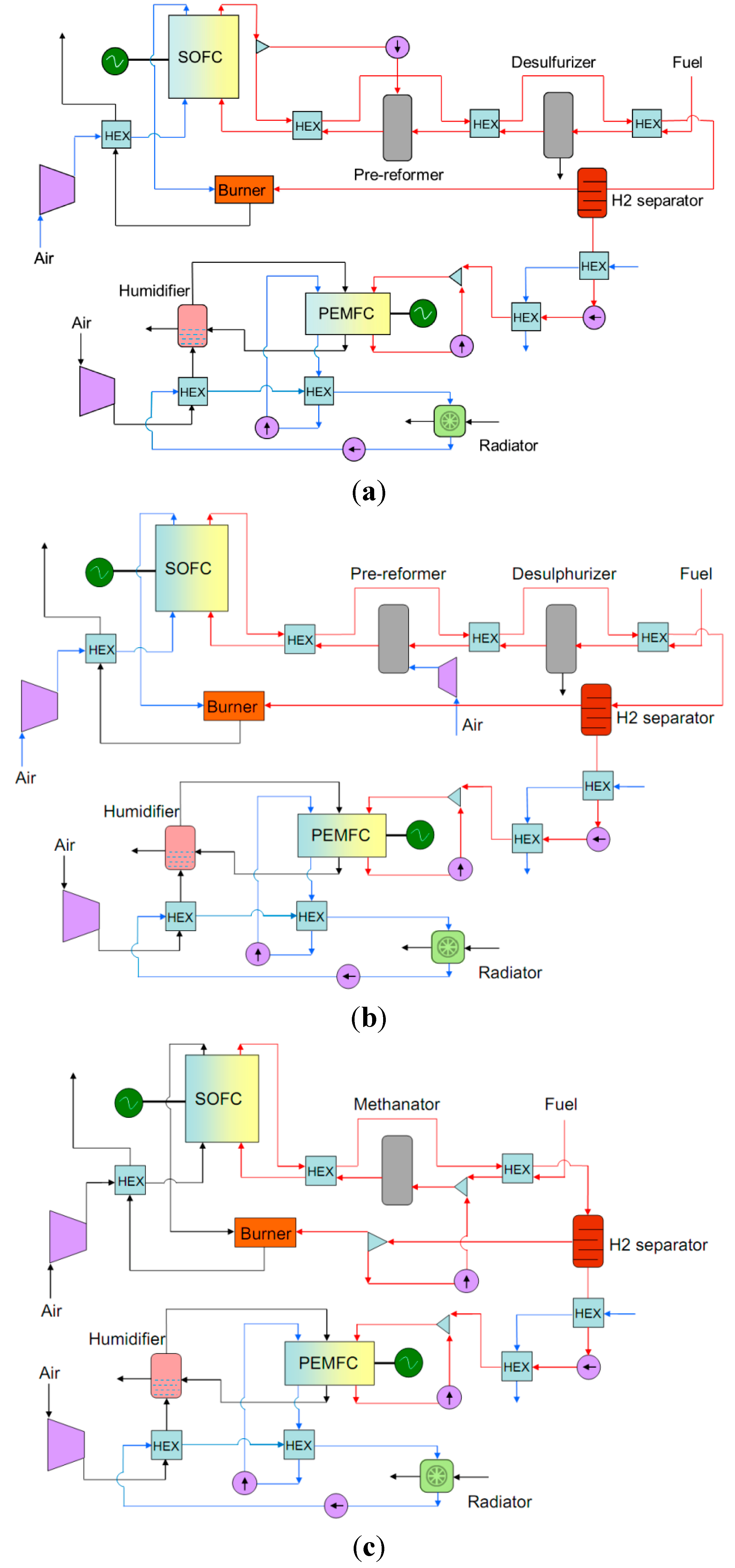
Two configurations are suggested for the SOFC plant; the first configuration with natural gas as fuel is shown in
Figure 1a. The fuel is preheated to 200 °C in a heat exchanger before it is sent to a desulphurization unit to reduce the sulphur content in the NG. As known, SOFCs are capable of direct internal reforming of light hydrocarbons (such as methane) at the anode, but not the heavier hydrocarbons. Using a high operating temperature, methane can be directly reformed to H
2 and CO. Due to small amount of heavier hydrocarbons in NG, an external reforming system is employed to avoid the thermal shock caused by the endothermic reforming reaction.
The heavier hydrocarbons in the NG are reformed in an Adiabatic Steam Reformer (ASR) type pre-reformer reactor, which is elaborated in the proceeding section. Another heat exchanger heats the fuel to the designated temperature of the pre-reformer. Due to the endothermic nature of the ASR reactions, the outlet temperature is not high enough to support direct feeding into the SOFC. In the present simulations, the temperature after the ASR reformer is found to be 469 °C. In this case, the fuel has to be pre-heated before entering into the fuel cell. The pre-reformed fuel is now sent to the anode side of the SOFC stacks. The fuel has a temperature of about 650 °C before entering the stacks. The operating temperature of the SOFC stacks is assumed to be 780 °C. The thermal energy of exhaust fuel is recovered for heating the incoming fuel at all the stages mentioned above.
Figure 1.
Schematics of combined Solid Oxide Fuel Cells (SOFC)-Polymer Electrolyte Fuel Cell (PEFC) plants, (a) For natural gas (NG) as fuel with Adiabatic Steam Reformer (ASR); (b) For NG as fuel with Catalytic Partial Oxidation (CPO) and (c) For dimethyl ether (DME) and ethanol as fuels.
Figure 1.
Schematics of combined Solid Oxide Fuel Cells (SOFC)-Polymer Electrolyte Fuel Cell (PEFC) plants, (a) For natural gas (NG) as fuel with Adiabatic Steam Reformer (ASR); (b) For NG as fuel with Catalytic Partial Oxidation (CPO) and (c) For dimethyl ether (DME) and ethanol as fuels.
For the cathode side of the SOFC, air is compressed in a compressor and then preheated in a recuperator to about 650 °C. The electrochemical reactions at the anode and cathode produce electrical power and heat at the expense of the fuel. Part of the heat that is released is utilized in the endothermic reforming process. The depleted fuel still contains some unutilized combustible fuel, such as hydrogen and carbon monoxide. Usually, the unutilized fuel is routed to a catalytic burner for oxidation. Conversely, in the present consideration, the off-fuel stream is passed through a hydrogen separation unit before being directed to the catalytic burner. Purified hydrogen is fed to the PEFC cycle for additional power generation. This is necessary to prevent poisoning of the Pt catalysts used in the PEFC stacks. Different H2 extraction techniques are discussed in detail under its specific header.
Note that even though all H2 was recycled back to the SOFC then there will always be some H2 left in the depleted fuel due to the utilization factor. Traditionally, this off-fuel will be burned in a catalytic burner to produce heat. However, in the present embodiment all H2 is separated for the PEFC while CO and H2O are recycled back to the SOFC anode. It will be shown that the total plant efficiency will be thus increased compared to a stand-alone SOFC cycle including anode recirculation.
Since the extracted hydrogen is at a temperature of around 650 °C, it is cooled down by a heat exchanger. It should be noted that the PEFC selected for this study operates at a higher pressure (2 bar) than to that of SOFC (1.1 bar). Therefore, a pump is employed for the PEFC cycle after the hydrogen cooler as seen in
Figure 1a. Again the temperature of H
2 increases in the pump, which is still higher than the inlet temperature for PEFC (60 °C). Another cooler cools it down before entering the PEFC. Water is used as a coolant for both the abovementioned heat exchangers.
The PEFC system includes a compressor, an air humidifier, set of heat exchangers and a stack which together build up the cathode circuit, the anode circuit and the cooling loop. On the cathode side, air is compressed, pre-cooled and humidified before entering the fuel cell stack at a pressure of less than 2 bar and a temperature around 60 °C. Hydrogen with a pressure of 2 bar and temperature around 60 °C enters the anode side of the stack. Since all the fuel does not react inside the stack, the rest is collected and send back to the anode stream via a recirculation pump. Compressed air passes through a humidifier which uses some of the water vapour from the cathode outlet to humidify the inlet air. The relative humidity of the air prior to PEFC stack is set to 95% in the calculations, although other values can be chosen. On the fuel side there is no humidifier and the fuel can reach the desired humidity by means of the water cross-over effect through the membrane from cathode to anode. Depending on stack power output, anode inlet humidity is between 91% and 100%. These operational values are based on the fuel cell design specifications [
25] and are reported to be in agreement with transient studies under different operating conditions [
32,
33]. For thermal management, two separate cooling circuits are used, denoted as inner and outer loops. In both loops water is used as a coolant. The inner loop is used for stack cooling and the water keeps the stack temperature around 70 °C. The rejected heat from stack via coolant in the inner loop is dedicated to the water in the outer loop with working temperature around 50–60 °C and the waste heat in the outer loop is rejected through a radiator fan. For PEFC, cathode inlet pressure of 1.8 bar with hydrogen inlet pressure of 2 bar have been suggested. High anode pressure ensures that no or very less nitrogen crosses over from cathode to the anode, thereby stabilizing its operation in the long run, see [
34].
The schematic of the second configuration is shown in
Figure 1b. DME, ethanol and methanol are used as fuels in this configuration. Unlike natural gas, these fuels do not require any desulphurization unit. Also, a methanator is used for cracking the fuel and increasing the amount of methane. Due to the endothermic nature of methane reforming inside the SOFC stacks, the need for excess air to cool down the SOFC stacks will decrease. This in turn decreases the air compressor work and thereby increases the plant efficiency. The fuel is preheated before the methanator where it is reformed to CH
4, H
2 and CO. A heat exchanger heats the fuel to the desired temperature for the SOFC inlet. Some part of exhaust fuel from the SOFC is recycled and mixed with the fuel at inlet of the methanator to provide the needed steam for the methanator reactions. For the high temperature recycle pump, long term durability is a problem. On the other hand for the low temperature pump, the off-fuel stream must be cooled to a low temperature which results in wastage of substantial thermal energy. In this study, an ejector (or the high temperature recirculation pump) is employed for simulations. The rest of the plant configuration remains the same as in the NG case, see
Figure 1b.
The main parameters for the plant are given in
Table 1. The number of SOFC stacks is assumed to be 10 and number of cells per stacks is assumed to be 75. The pressure drops in the cathode and anode sides of SOFC are assumed to be 0.05 and 0.01 bars, respectively. Since the PEFC provides a one-eighth fraction of the total power, only one stack with 25 cells would be enough in the studied system configurations. Pressure drops of 0.14 and 0.39 bar are assumed for the anode and cathode sides of the PEFC, respectively. Furthermore, the utilization factor for the SOFC cells is assumed to be 0.8, whereas for the PEFC, stoichiometric ratios of 1.6 for H
2 and 1.8 for air are used from the product datasheet of the fuel cell module [
25]. The pressure drops for all heat exchangers are assumed to be 0.01 bars. As the system is designed for low-scale power, the fuel and air mass flows tend to be small, resulting in lower turbomachine efficiencies. Therefore, the compressor isentropic efficiency and mechanical efficiency are assumed to be 0.7 and 0.7, respectively, while the generator efficiency is assumed to be 0.97.
Table 1.
Main parameters for the design point calculations in fuel cell cycles.
Table 1.
Main parameters for the design point calculations in fuel cell cycles.
| Fuel Cell | SOFC | PEFC |
|---|
| Compressor intake temperature, (°C) | 25 | 25 |
| Compressor isentropic efficiency | 0.7 | 0.6 |
| Compressor mechanical efficiency | 0.7 | 0.65 |
| Cathode inlet temperature, (°C) | 650 | 60 |
| Cathode outlet temperature, (°C) | 780 | 68 |
| Fuel utilization factor | 0.80 | 0.62 |
| Number of cells in stack | 75 | 25 |
| Number of stacks | 10 | 1 |
| Cathode side pressure drop ratio, (bar) | 0.05 | 0.39 |
| Anode side pressure drop ratio, (bar) | 0.01 | 0.14 |
| Heat exchangers pressure drops, (bar) | 0.01 | 0.01 |
| Fuel inlet temperature, (°C) | 25 | – |
| Anode inlet temperature, (°C) | 650 | 60 |
| Anode outlet temperature, (°C) | 780 | 68 |
| Generator efficiency | 0.97 | 0.97 |
3.2. Hydrogen Separation
For a PEFC, pure hydrogen is needed and therefore one of the key aspects of this study is the extraction of hydrogen from the off-fuel stream and its utilization in the PEFC. The depleted fuel from the SOFC contains a fraction of usable fuel, so the H2 production process must be efficient and effective. In this section, we discuss some methods of purifying the off-fuel for H2 separation. Two different configurations can be adapted for a hydrogen extraction system. One is producing hydrogen using the excess heat of an SOFC module and the exhaust gas with an extra reformer operated independently. Another is extracting hydrogen directly from the off-fuel by purifying the off-fuel.
The former method can further be classified into pressure swing adsorption (PSA), temperature swing adsorption (TSA), CO
2 absorber, and a membrane reformer. PSA is a mature technique and it is easy to adapt the PSA system to the present SOFC and hydrogen production system. In this process, the reformed gas first passes through the shift converter and most of CO is converted there to H
2 in the presence of water. Then CO and CO
2 are adsorbed at the PSA and only H
2 is collected. In TSA systems, by swinging the temperature, CO and CO
2 can be removed from the off-fuel. CO
2 absorbents are another way of purifying the fuel once CO is converted into CO
2 in the water shift reactors. These materials can absorb and desorb CO
2 reversibly above and below a certain temperature. A more effective way for purifying the reformed gas is using a membrane reformer. Selective removal of hydrogen in a membrane reformer can reduce the reforming temperature compared with conventional processes [
11]. The advantage of using the off-fuel purifying system is that the configuration of the system can be simple. One more merit is that it is not necessary to pay attention to the reformer temperature. Here, the hydrogen purifying system is selected for the sake of simplicity.


