
Detuning Minimization of Induction Motor Drive System for Alternative Energy Vehicles

Department of Electrical Engineering, College of Engineering, American University of Sharjah, Sharjah 2666, UAE
Energies 2015, 8(9), 9117-9136; https://doi.org/10.3390/en8099117
Submission received: 9 April 2015
/
Revised: 3 August 2015
/
Accepted: 18 August 2015
/
Published: 26 August 2015
(This article belongs to the Special Issue Advances in Plug-in Hybrid Vehicles and Hybrid Vehicles)
Abstract
:This paper evaluates different types of AC machines and various control techniques for their suitability for the drive system of Alternative Energy Vehicles (AEV). An Indirect Field Oriented (IFO) drive system for the AEV application is chosen and its major problem of detuning is addressed by designing an offline and an online rotor resistance adaptation technique. The offline scheme sets the slip gain at various operating conditions based on the fact that if the rotor resistance is set correctly and field orientation is achieved, then there should be a linear relationship between the torque current and the output torque. The online technique is designed using Model Reference Adaptive System (MRAS) for the rotor resistance adaptation. For an ideal field oriented machine, the rotor flux along the q-axis should be zero. This condition acts as a reference model for the proposed MRAS scheme. The current model flux observer in the synchronous frame of reference is selected as an adjustable model and its rotor resistance is tuned so that the flux along the q-axis becomes zero. The effectiveness of the offline tuning scheme is evident through performance validation of the drive system, which is implemented in a real Ford vehicle. The experimental results obtained while driving the test vehicle are included in the paper while the proposed online scheme is validated on a 3.75 kW prototype induction motor.

1. Introduction
DC machines are not a viable option for the Alternative Energy Vehicles (AEV) because they have low levels of efficiency, lowered power to weight ratio, a high-cost maintenance, and have limited high-speed operation capabilities. AC machines are a better alternative for Battery-powered Electric Vehicles (BEV), Hybrid Electric Vehicles (HEV), and Integrated Starter Alternator (ISA) drive systems. The induction motor, the switched reluctance motor, and the permanent magnet motor are three competitor machines that are being examined for their efficacy. Although the switched reluctance motor has a simpler stator winding and rugged rotor structure, it has problems of torque ripple, noise, and vibrations. The Permanent Magnet Synchronous (PMS) motor, on the other hand, is more efficient but relatively more expensive. Moreover, its magnets are sensitive to high temperatures. Nevertheless, advancements in the permanent magnet technology and ongoing reduction in the permanent magnet’s cost demonstrate that the future of PMS machines is promising. The induction motor, on the other hand, is well known and accepted because of its wide-speed range, complete de-energization, ruggedness, and lowered cost.
The 48-volt ISA system is currently explored as a potential power net by the automotive industry. For an ISA application, a PMS motor fares better than the AC induction motor because of its higher efficiency, especially when an ISA is powered by a smaller-sized battery than a BEV. Thus, an AC induction motor is either better, or at least a comparable, alternative for BEV and HEV applications because of the associated advantages mentioned above. Interestingly, another deciding factor is the experience and technology that the major automotive companies have developed. Ford and General Motors are more inclined towards the induction machine, while Toyota and Honda are choosing the PMS machine for almost all of their AEV applications.
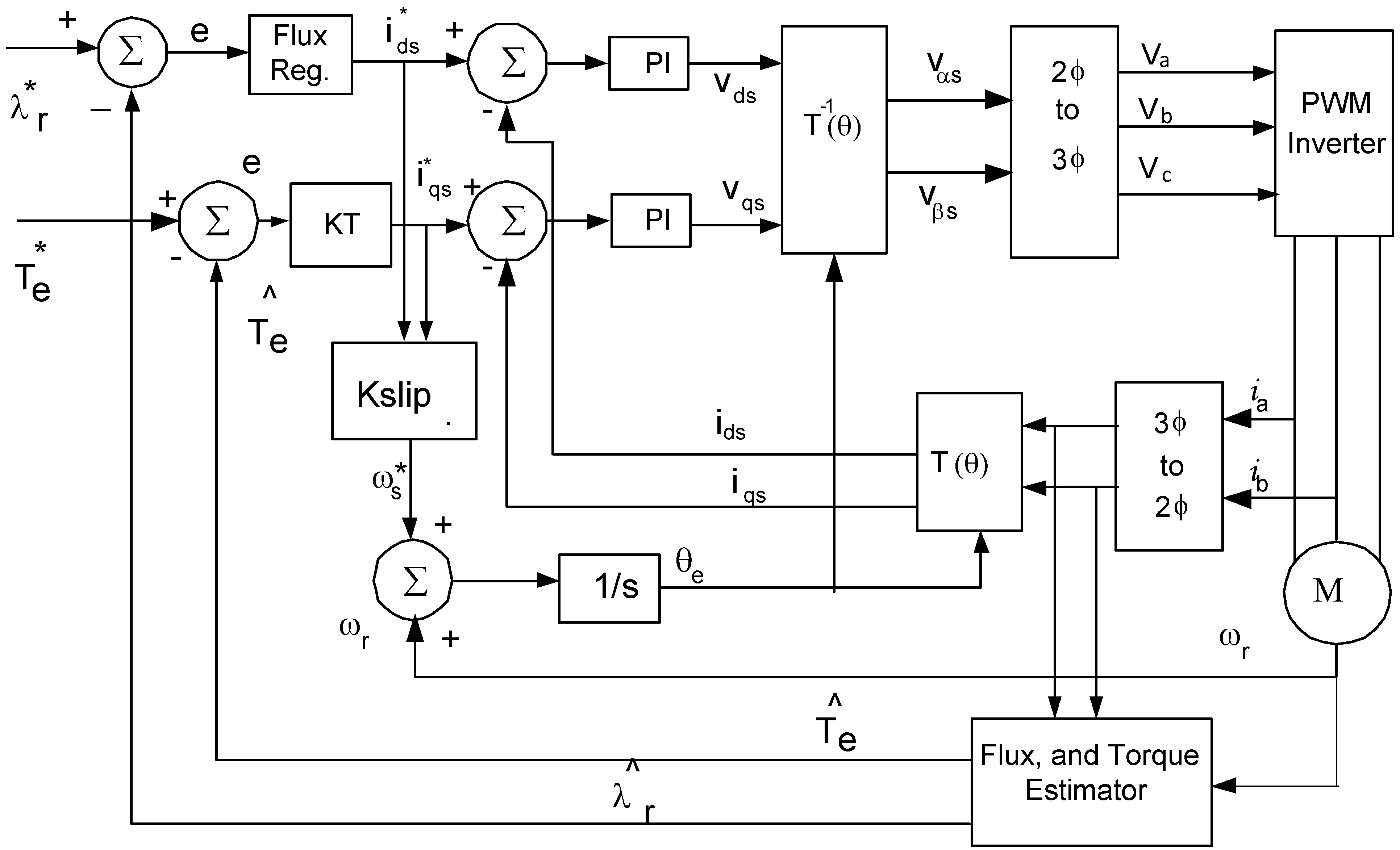
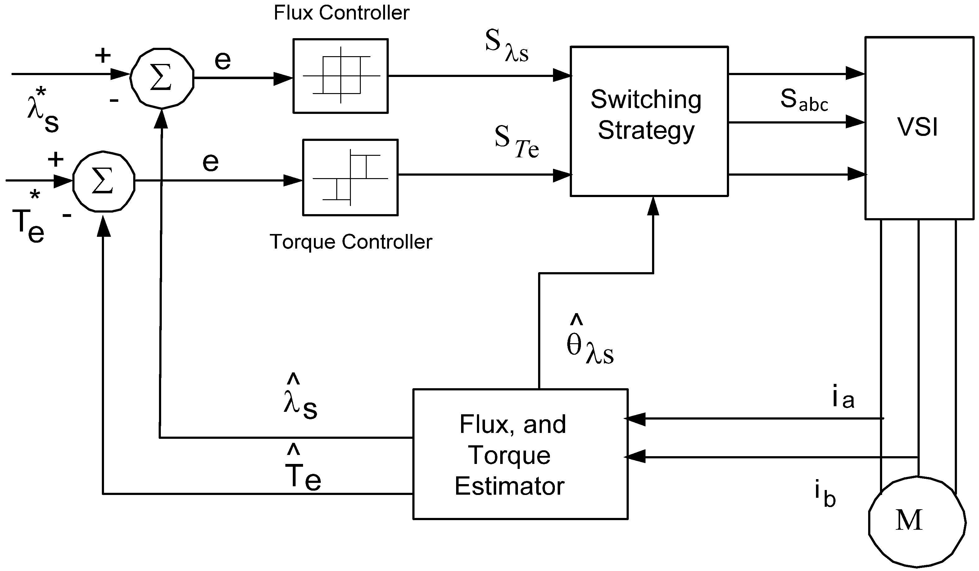
The Field Oriented Control (FOC) includes the Indirect Field Orientation (IFO) and Direct Field Orientation (DFO) control [1] and the Direct Torque Control (DTC) [2] are the two main control techniques for AEV drive systems. Figure 1, Figure 2 and Figure 3 shows block diagrams for IFO, DFO, and DTC drive systems, respectively [3]. For speed control, the torque control loop will be replaced with the speed control loop for the FOC. Since the DTC regulates torque directly, another block for speed regulation needs to be added so that the output is the torque command. The DTC, shown in Figure 3, has the following features: a fast dynamic response, simplicity of design since it does not require stator current and flux regulation loops required by the FOC, and robustness against the parameters’ variation. The basic DTC drive system also has a sensorless structure and applies a bang-bang torque and flux control. Despite its features, the DTC drive system is lacking because it has low speed flux, and torque estimation and control, high current, and torque ripples. The torque ripples create vibrations, which make the DTC less appealing for automotive applications. Despite its negative attributes, the DTC is a worthy candidate for the ISA application because the ISA mostly operates in the cranking mode with a motor requiring only a good dynamic performance. The torque ripples of the DTC drive system in the steady state operation are not a major problem because, as a starter, the ISA operation time is short; in the steady state, it mostly operates as an alternator. For BEVs, it is only the AC motor drive that propels the vehicle both in the dynamic and steady state operations. Thus, the DTC is not an ideal choice because of its torque ripples, which makes the FOC more suitable for BEVs. The HEV has generally three basic configurations: series hybrid, parallel hybrid, and series parallel hybrid. The AC machine operation for HEV varies based on its architecture and the designed hybrid features in the dynamic and steady state operations. The FOC is a better choice only if the machine operation in the steady state condition increases significantly. Otherwise, the DTC can be selected for an ISA type of operation.
Figure 1.
Indirect Field Oriented (IFO) drive system.

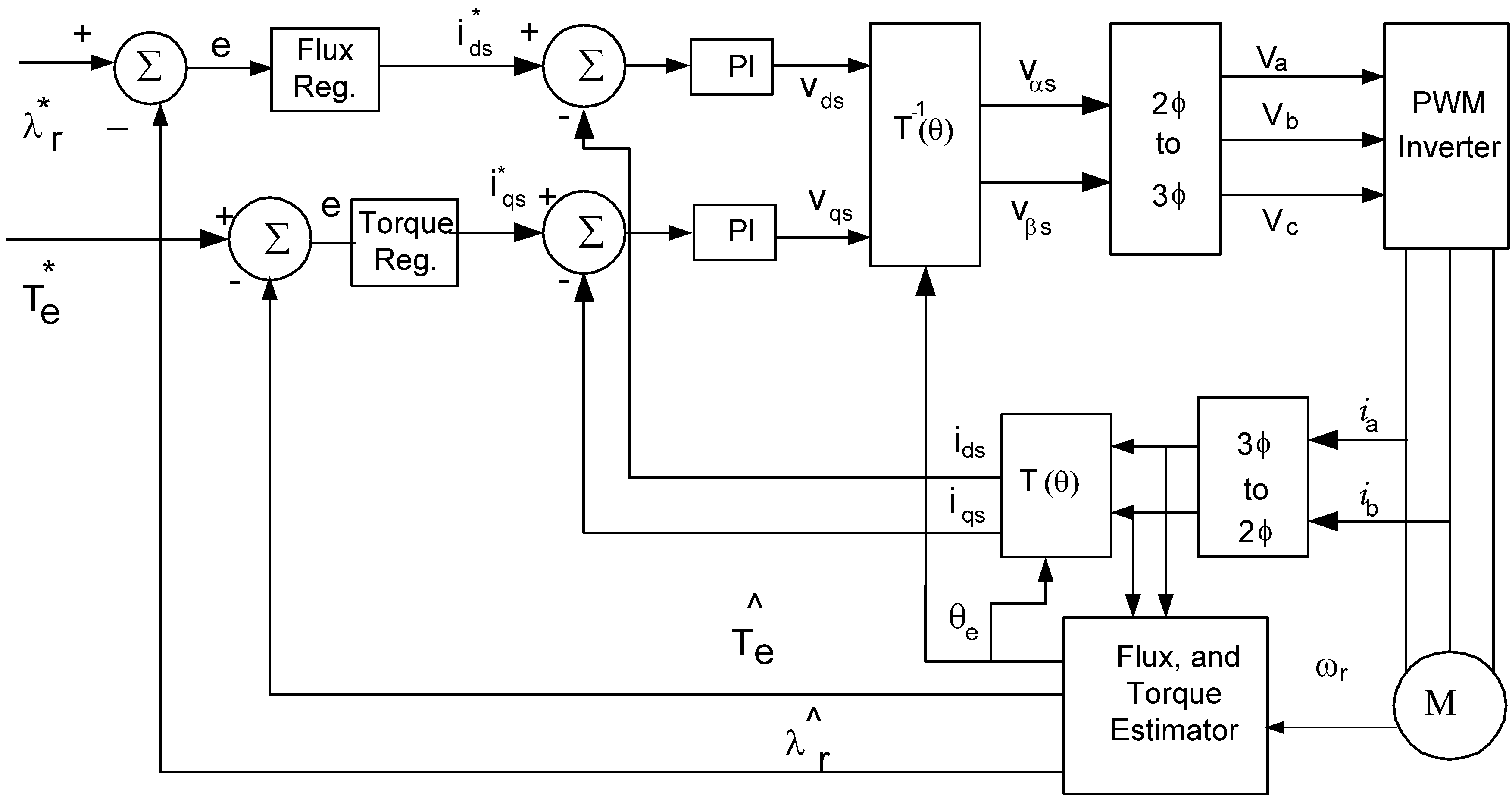
Figure 2.
Direct Field Oriented (DFO) drive system.

Figure 3.
Direct Torque Controlled (DTC) drive system.

Taking into consideration the two field oriented control techniques, DFO control is preferred over the IFO control because IFO is a feed-forward open loop based control system while DFO is a feedback closed loop control. However, DFO is sensitive to stator resistance, which is the core of the flux and its angle estimation. The IFO controller, as shown in Figure 1, is realized by an accurate slip frequency control, a necessary and sufficient condition for keeping the machine field oriented. Accurate speed information is a must for an IFO drive system, which potentially comes from the speed sensor or by designing a speed estimator. The IFO drive system is advantageous because it does not require explicit stator or rotor flux estimation since the optimal flux setting can be realized by setting the flux current ids and, thus, omitting the flux regulation block. The rotor flux oriented IFO controller, shown in Figure 1, still remains one of the most attractive choices [4,5] and is a widely used control technique for AEV drive systems [3,6,7]. Therefore, this work focuses on an IFO drive system and presents its performance enhancement.
The IFO control, realized by an accurate slip frequency control, requires the parameters of rotor inductance and resistance for the slip calculation. The IFO is inherently parameter sensitive because the rotor inductance is a function of current and speed, while the rotor resistance and, hence, the rotor time constant (Tr) vary substantially with temperature changes. The ratio of command Tr to actual Tr can range from 0.5 to 1.5 in practice. This process of deviation of Tr from its actual value to the command value is known as detuning of the machine. Detuning is a long standing problem. Although it has been widely studied over the last three decades, an effort to make the tuning of rotor time constant simpler and accurate is still being researched. The three different approaches adopted for overcoming the detuning problem are: (i) designing an intelligent controller, which can work effectively even when the machine parameters are inaccurate [8,9,10,11]; (ii) designing an offline rotor resistance adaptation technique [6]; and (iii) designing an online rotor resistance identification mechanism [7,12,13,14,15,16,17,18,19,20,21,22,23].
The intelligent controllers [8,9,10,11], although able to overcome the controller performance degradation due to detuning, do not correct the rotor resistance, which results in lesser torque per amps. The offline scheme [6] has been widely adopted by the industry but it cannot incorporate all the operating conditions. Moreover, it also requires intensive controller characterization before the machine can be put into operation. Finally, the online resistance adaptation [12,13,14,15,16,17,18,19,20,21,22,23] is most appropriate choice because it can adjust the rotor time constant under all of the operating conditions.
This paper proposes and compares an off-line tuning method [6] and another Model Reference Adaptive System (MRAS) based online tuning scheme [14] for the rotor resistance adaptation and analyzes their effectiveness through experimental study. The off-line scheme propounded in this paper is a practical one and its performance is validated for the ISA application. The online rotor resistance adaptation techniques [12,13,14,15,16,17,18,19,20,21,22,23] are designed based on the neural network, or using sliding mode observer, or are realized by the Model Reference Adaptive Scheme (MRAS). For example, the online rotor resistance adaptation technique presented in [17] is based on an artificial neural network in which the error between the rotor flux linkages, based on a neural network model and a voltage model, is back propagated to adjust the weights of the neural network model for the rotor resistance estimation. A Luenberger-sliding mode observer with parameter adaptation algorithm is proposed in [18] to compensate for the rotor resistance variation effects. An adaptive variable structure identifier that provides finite time convergent estimate of the induction motor rotor resistance under feasible persistent of excitation condition is presented in [20]. A comparison between various model reference adaptive schemes (MRAS) has been presented in [21] and it has been documented that an MRAS based technique can effectively work for the rotor resistance adaptation. This paper also proposes an MRAS based online rotor resistance adaptation scheme [14]. The proposed technique is simpler than the ones presented in the past [16,17,18,19,20,21,22,23], does not require rigorous tuning like neural net, and proved to effectively adjust the rotor resistance on a prototype 3.75 kW induction machine.
2. Rotor Flux Oriented IFO Control with Off-Line Tuning
The Current Model Flux Observer (CMFO) of the induction machine in the stationary frame of reference is represented by the following set of equations [24]:
The resultant rotor flux and the flux angle are calculated as:
The rotor flux oriented indirect field orientation is realized by locking the resultant flux λr with the synchronously rotating d-axis vector. The q-axis is perpendicular to the d-axis and therefore the flux along the q-axis should be zero. In doing so, the current applied along the d-axis will independently control the flux, while the current along the q-axis will control the torque. In the rotor flux oriented IFO, the condition of locking the d-axis with the resultant flux vector, or alignment of the resultant flux vector with the d-axis, is guaranteed assuming that the entire flux is aligned along the d-axis of synchronous frame of reference, which imposes the following condition on the machine slip:
For the IFO control, an accurate command slip is the deciding factor for maintaining the field orientation, which requires precise rotor time constant information. The IFO control is realized by imposing the slip condition specified by Equation (5). The mechanical motion, and torque equation in the synchronous frame of reference, can be written as follows [24]:
The rotor flux orientation control scheme is simple and results in decoupling of the flux and torque components forcing the flux along q-axis to zero. This decouples the flux control from the torque control, simplifying the torque equation [5] to:
In practice, the motor parameters, specifically the rotor resistance, are sensitive to temperature and relative speed of the machine. Consequently, if the resistance in the slip equation is not set properly, the decoupled control of the flux and the torque is lost. To overcome this problem, an off-line gain scheduler is designed and implemented. The gain scheduler, proposed in this work, tunes the machine’s parameters in a simple and efficient manner, and is realized by designing a slip gain (Kslip) which modifies Equation (5) as [6]:
Slip gain Kslip is a key control parameter in the implementation of indirect rotor flux orientation control. If the slip gain is set properly, the highly complicated induction machine model becomes decoupled and controller design is significantly simplified. One criterion designed to detect the proper setting of Kslip is based on the following definition:
“Assuming that the gain is set correctly and rotor flux orientation is achieved, then the torque Equation (7) can be expressed as [6]:
If ids is maintained constant, then the output torque would be a linear function of iqs. Therefore, one way to tune Kslip is to adjust Kslip so that a linear relationship between the output torque and iqs is achieved”. The parameter KT in Equation (10) serves as a scaling factor between the command current and the torque command , as indicated in Figure 1. Therefore, KT and Kslip can be tuned simultaneously using the proposed methodology.
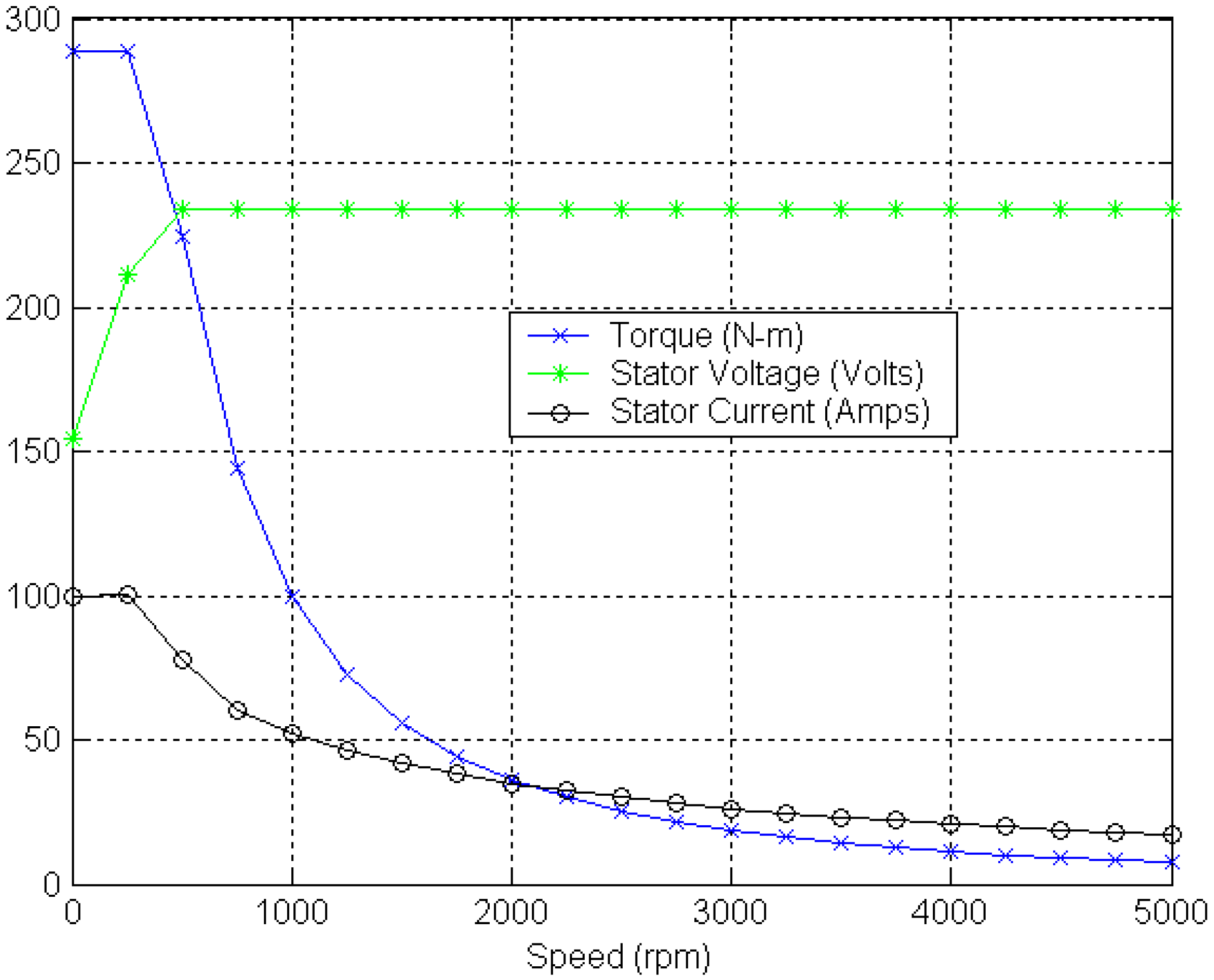
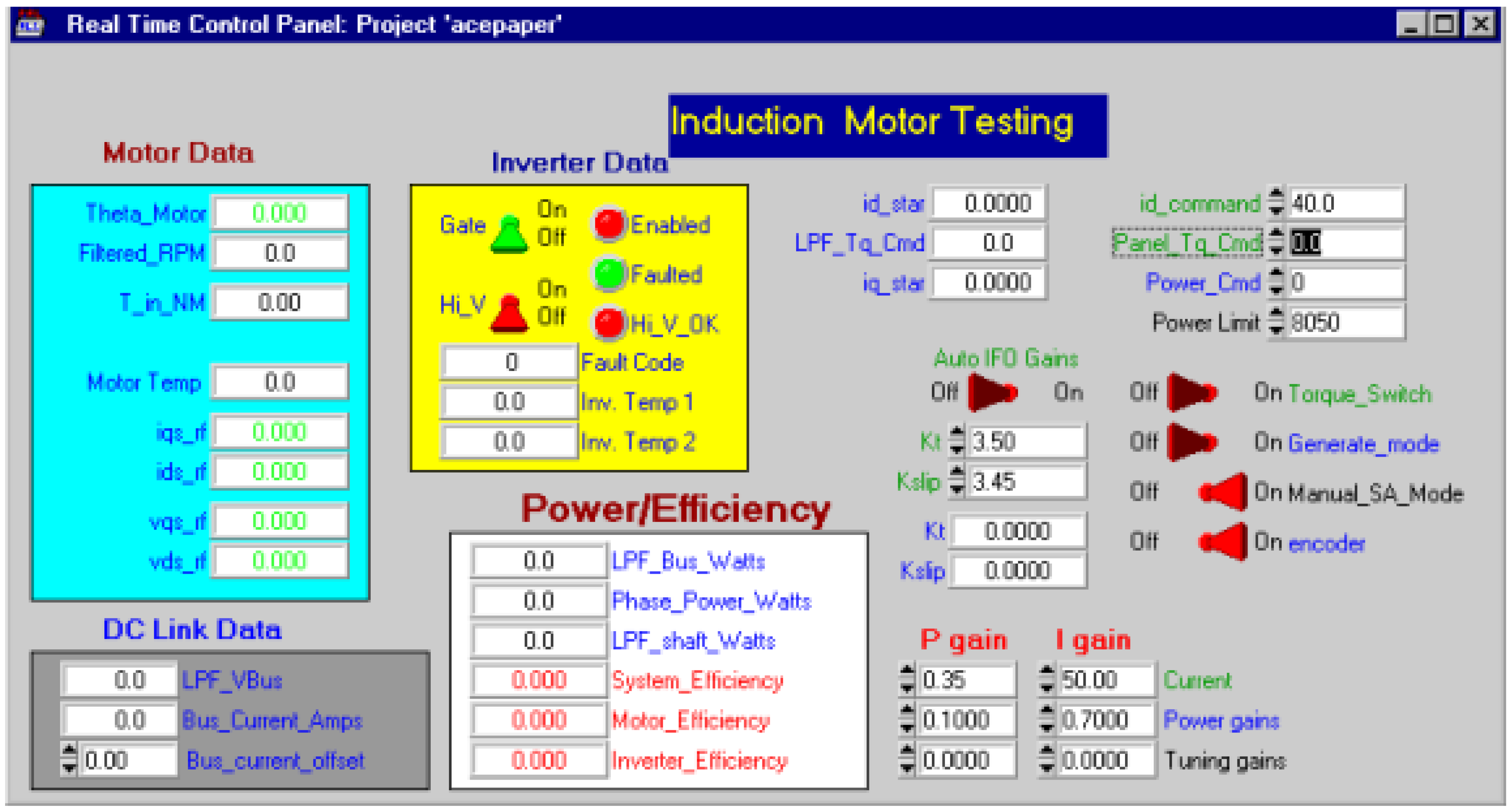
This offline parameter tuning scheme is applied on an 8 kW induction which has been deployed in a real vehicle for the ISA operation. The motor parameters and torque speed characteristics are shown in Table 1 and Figure 4, respectively. The motor has a limited constant torque region while its field weakening region has been extended up to 5000 rpm. This is because a constant torque is required only for the engine starting up to about 800 rpm while most of the time the machine is operating in the generation mode. The experimental setup includes an 8 kW induction motor, an IGBT inverter, and a flexible high performance advanced controller (ACE) [25] for electric machine. The DSP on the CPU board performs all real time control functions, while a microprocessor performs downloading, data logging, and data communication functions. Figure 5 [25] shows the real time control panel Graphical User Interface (GUI) built for testing an induction machine. By using this GUI, it is very convenient to change control parameters and immediately see the effects of that change. Any control input or control parameter can be set up to be driven from the GUI and hence can be changed in real time. Likewise, any system measured or calculated output can be displayed on the GUI. Many different types of control and display widgets are provided, including strip charts, switches, and numeric displays. These features make the ACE development system very flexible and efficient. For example, PI current regulator control gains (shown at the bottom right of the control panel in Figure 5 for an induction machine can be changed while the system is running. The built-in datalogger can be easily used to see the exact effects of that change in gain on the commanded phase voltages and measured phase currents. The datalogger is designed so that all of the data is coherent—that is, sampled from the same control loop iteration and thus perfectly synchronized and guaranteed to be valid [25].
Figure 4.
Torque speed characteristics of an ISA machine.


| Motor Parameters | Values |
|---|---|
| Design Voltage | 300 V |
| Rated Power | 8 kW |
| Poles | 12 |
| Base Speed | 300 rpm |
| Peak Torque | 280 Nm |
Figure 5.
Control panel for induction motor testing.

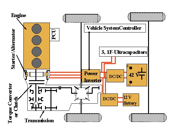
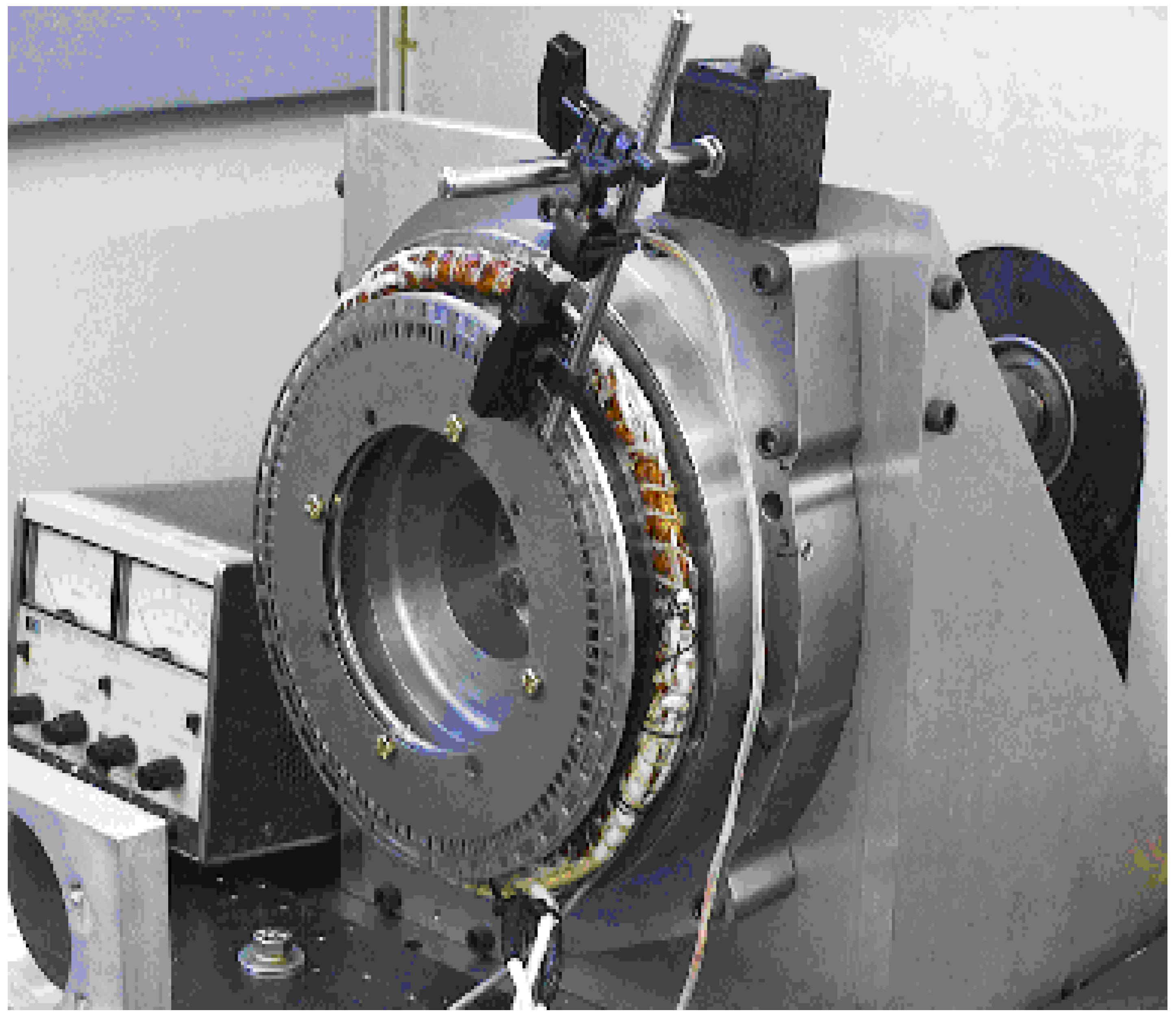
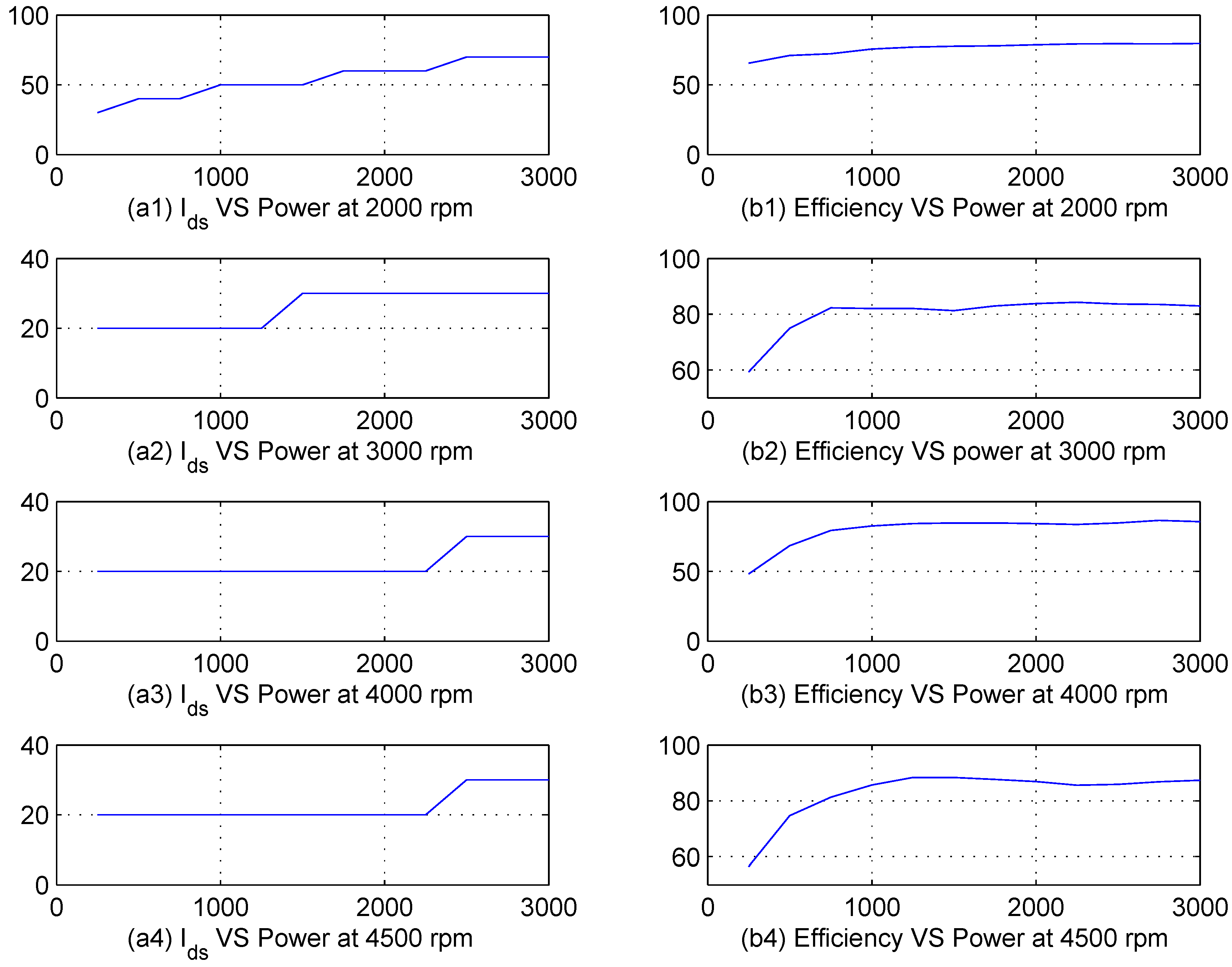
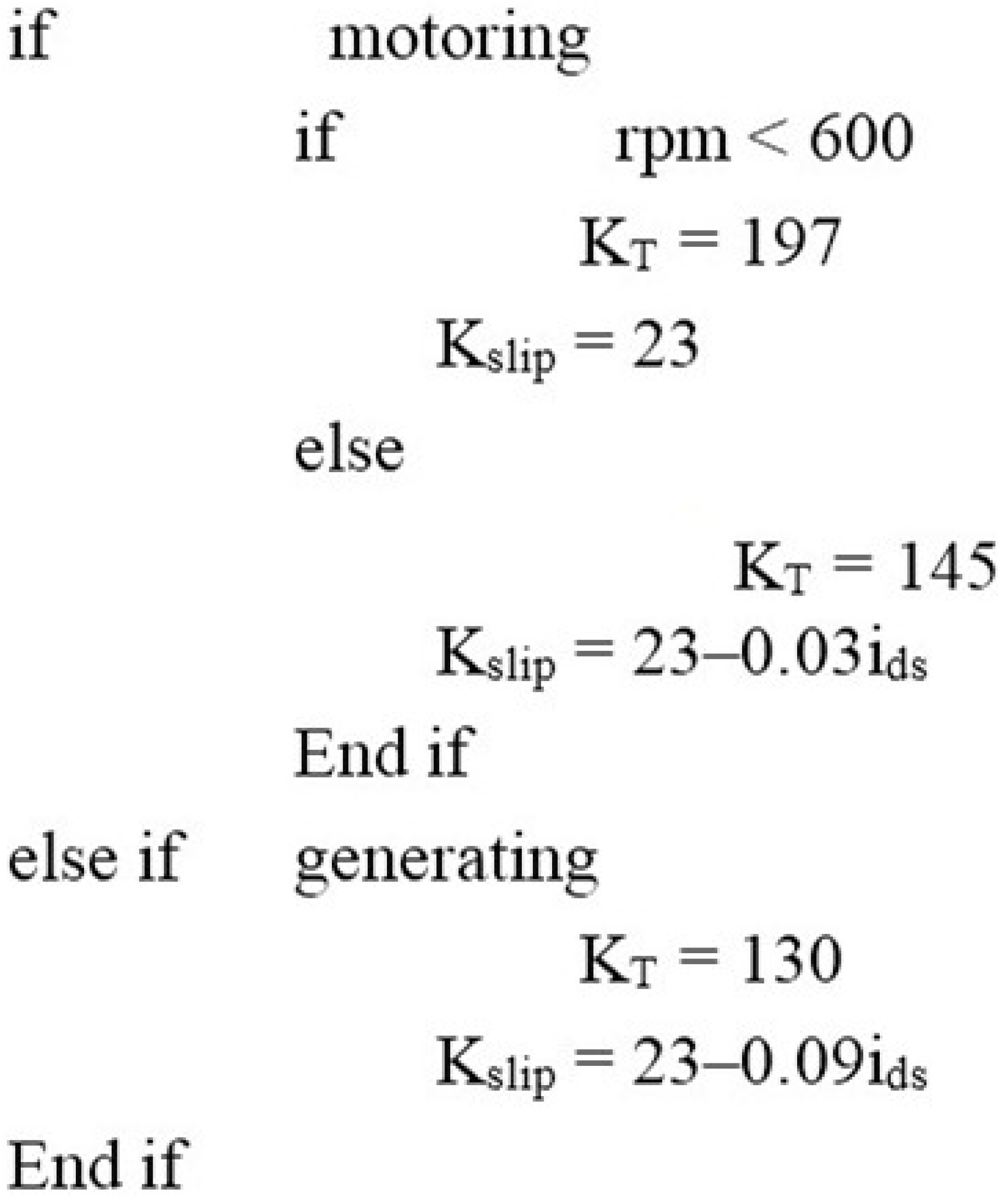
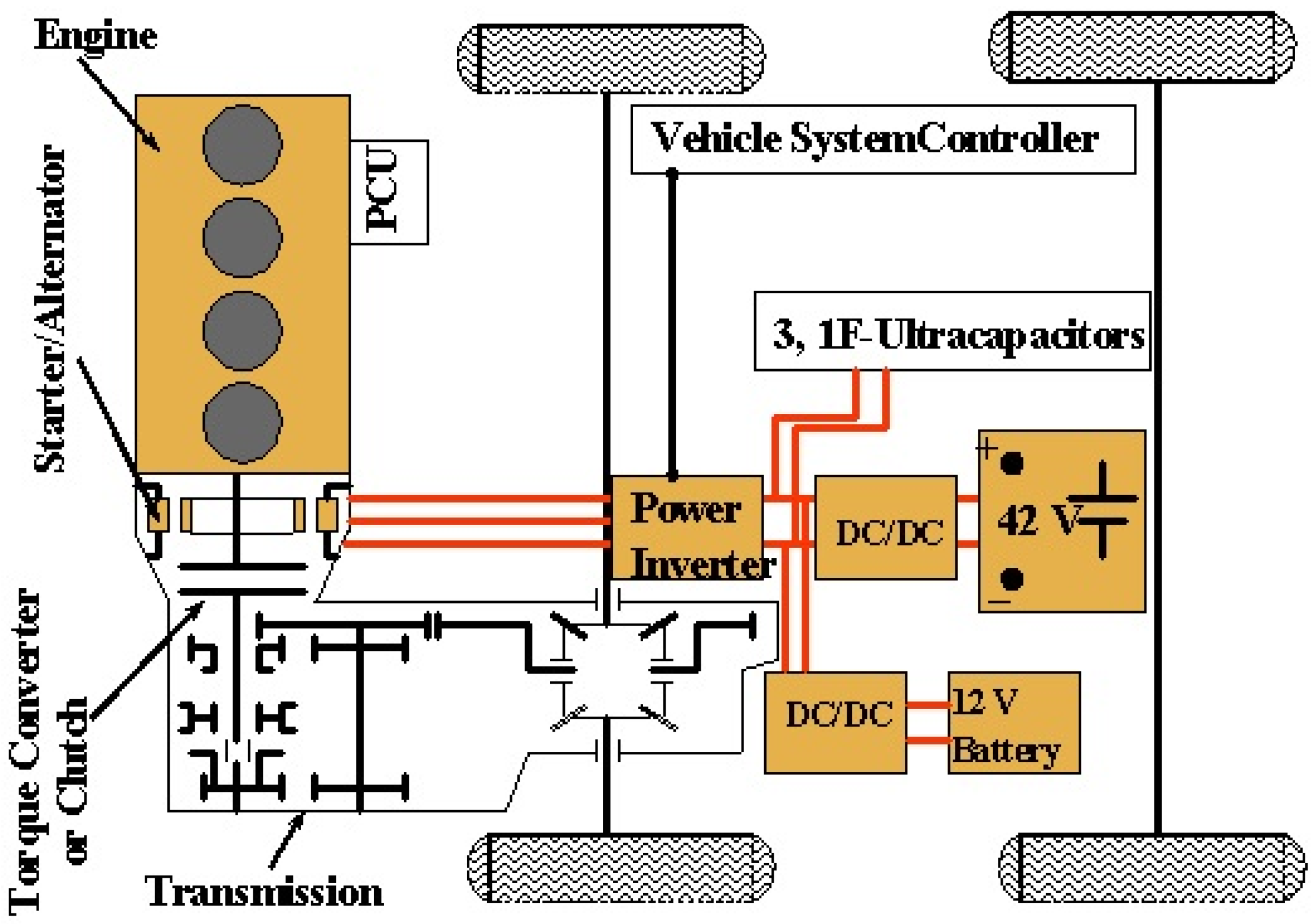
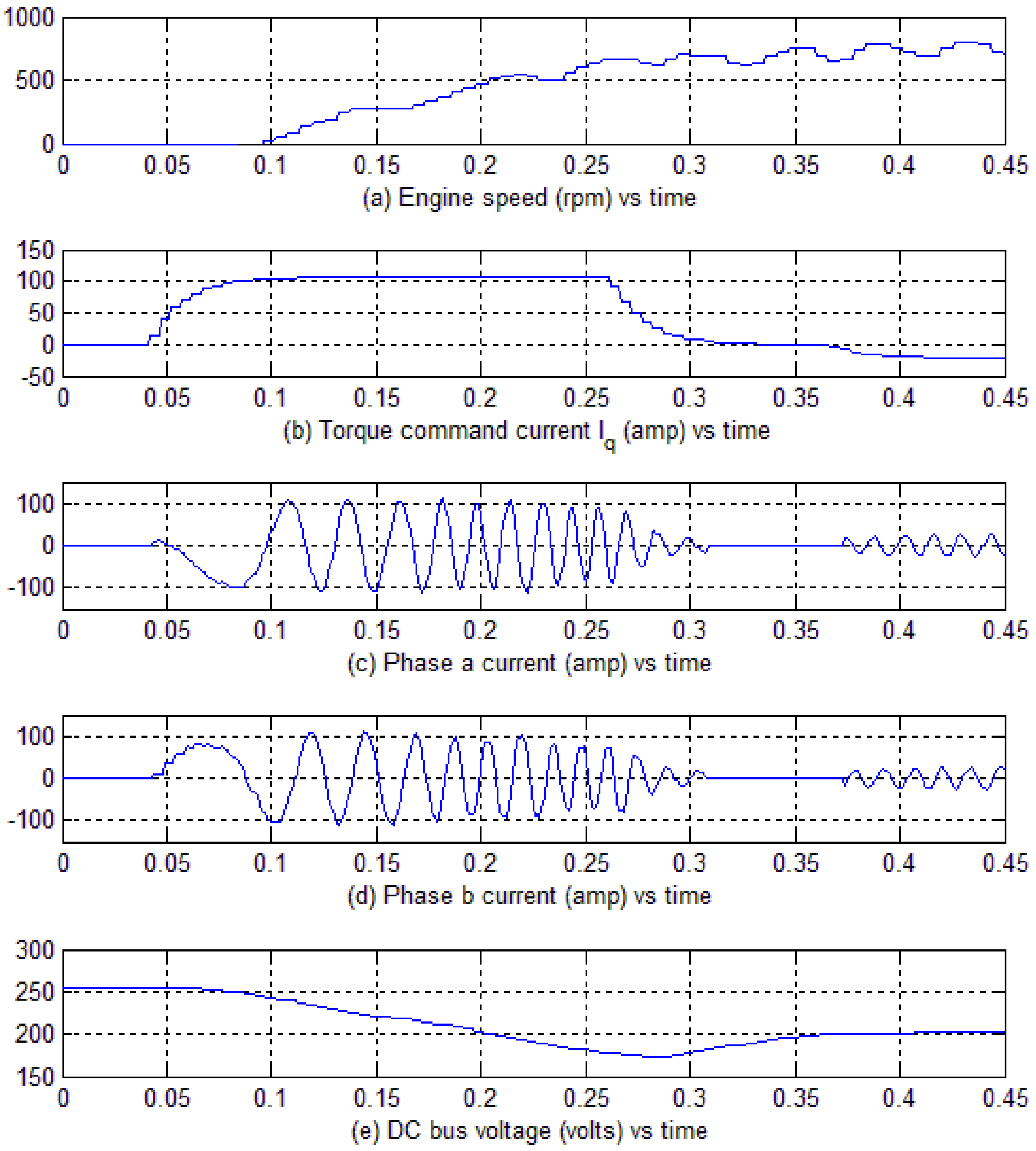
The motor is put on the dynamometer as shown in Figure 6 and operated at different speeds and loads both in motoring and generating modes of operation for tuning the KT and Kslip. The rotor flux oriented drive system has two independent inputs: torque command and flux command. Normally the operating conditions, e.g., speed and torque, are governed by the motor application. The flux setting provides a degree of freedom; i.e., ids can be selected to achieve additional objectives such as maximizing the system efficiency while meeting the torque demand. In Figure 7, the flux optimization is demonstrated at speeds of 2000, 3000, 4000 and 4500 rpm. The optimum flux current and efficiency are plotted in each trace for each speed [3]. The Figure 7a1–a4 show the optimal flux current setting for speed of 2000, 3000, 4000 and 4500 rpm respectively at different power levels while Figure 7b1–b4 show the optimal efficiency measured at the corresponding points. Experimental results reveal that KT and Kslip depend upon the operating mode of the machine (motoring/generating), operating speed, and flux current setting i.e., ids. After a careful study of the test data, based on the criteria outlined above, a gain scheduler for KT and Kslip is developed and implemented in the induction motor controller. As an example, one such gain scheduler designed for the starter alternator application both for the motoring and generating modes of operation for a speed range of 600 rpm is shown in the Figure 8. This gain scheduler is integrated for an IFO drive system of ISA and is implemented in the Ford European Mendo. The overall system shown in Figure 9 [6] includes a three-phase IGBT inverter, induction motor as a starter alternator, two dc/dc converters, a 42 volt lead acid battery and three 1-F ultracapacitors. The experimental results while driving the vehicle on road are demonstrated in Figure 10. In this figure, Figure 10a shows the engine speed, Figure 10b shows the torque command current in the synchronous frame of reference set by the controller to attain the desired speed. The actual motor phase a and b currents are plotted in Figure 10c,d respectively while the DC bus voltage is shown in Figure 10e. Figure 10a shows that the designed controller can start the engine and bring it to a speed of about 800 rpm in less than 0.3 s and afterwards, at about 0.37 s, it works as a generator to charge the battery by applying a negative iqs as shown in Figure 10b. Thus, the gain scheduler designed in Figure 8 works effectively to keep the machine field oriented and get an instantaneous torque response for operating the vehicle. There are other such gain schedulers designed for different ranges of speed and programed in the motor’s controller. Furthermore, the starter and alternator actions of the ISA can be observed from the subplot (e) in which the inverter DC bus voltage initially decreases during the motoring action from 0.1 to about 0.3 s and then it starts increasing because of the generator action realized by a negative iqs.
Figure 6.
Off line tuning of Induction motor for gain scheduler.

Figure 7.
Experimental results for efficiency and flux current. a1–a4: optimal flux current versus power at 2000, 3000, 4000 and 4500 rpm respectively; b1–b4: Efficiency calculation with optimal flux level at 2000, 3000, 4000 and 4500 rpm respectively.
Figure 7.
Experimental results for efficiency and flux current. a1–a4: optimal flux current versus power at 2000, 3000, 4000 and 4500 rpm respectively; b1–b4: Efficiency calculation with optimal flux level at 2000, 3000, 4000 and 4500 rpm respectively.

Figure 8.
Off line tuning of gain scheduler.

Figure 9.
The ISA system design.

Figure 10.
In vehicle testing result for the ISA with the proposed gain scheduler. (a) Engine speed in rpm; (b) Torque command current; (c) Motor phase a current; (d) Motor phase b current; (e) DC bus voltage.
Figure 10.
In vehicle testing result for the ISA with the proposed gain scheduler. (a) Engine speed in rpm; (b) Torque command current; (c) Motor phase a current; (d) Motor phase b current; (e) DC bus voltage.

3. Online Rotor Resistance Adaptation
The online rotor resistance adaptation method analyzes various flux observer structures to explore their suitability for the rotor resistance adaptation. An observer or estimator has an integration process model that estimates the desired state. This integration process model can be implemented with or without a feedback loop. The feedback loop corrects the error and hence improves the estimation’s accuracy. An observer without a feedback loop is called an open loop observer whereas one with the feedback loop is called a closed loop observer. Therefore, the open loop observer is essentially a real-time simulation of the physical process. The current model open loop flux observer and voltage model open loop flux observer are the two most commonly used open loop flux observers. The current model flux observer in the stationary frame of reference, given by Equation (2), can be transformed in the synchronous frame of reference as [24]:
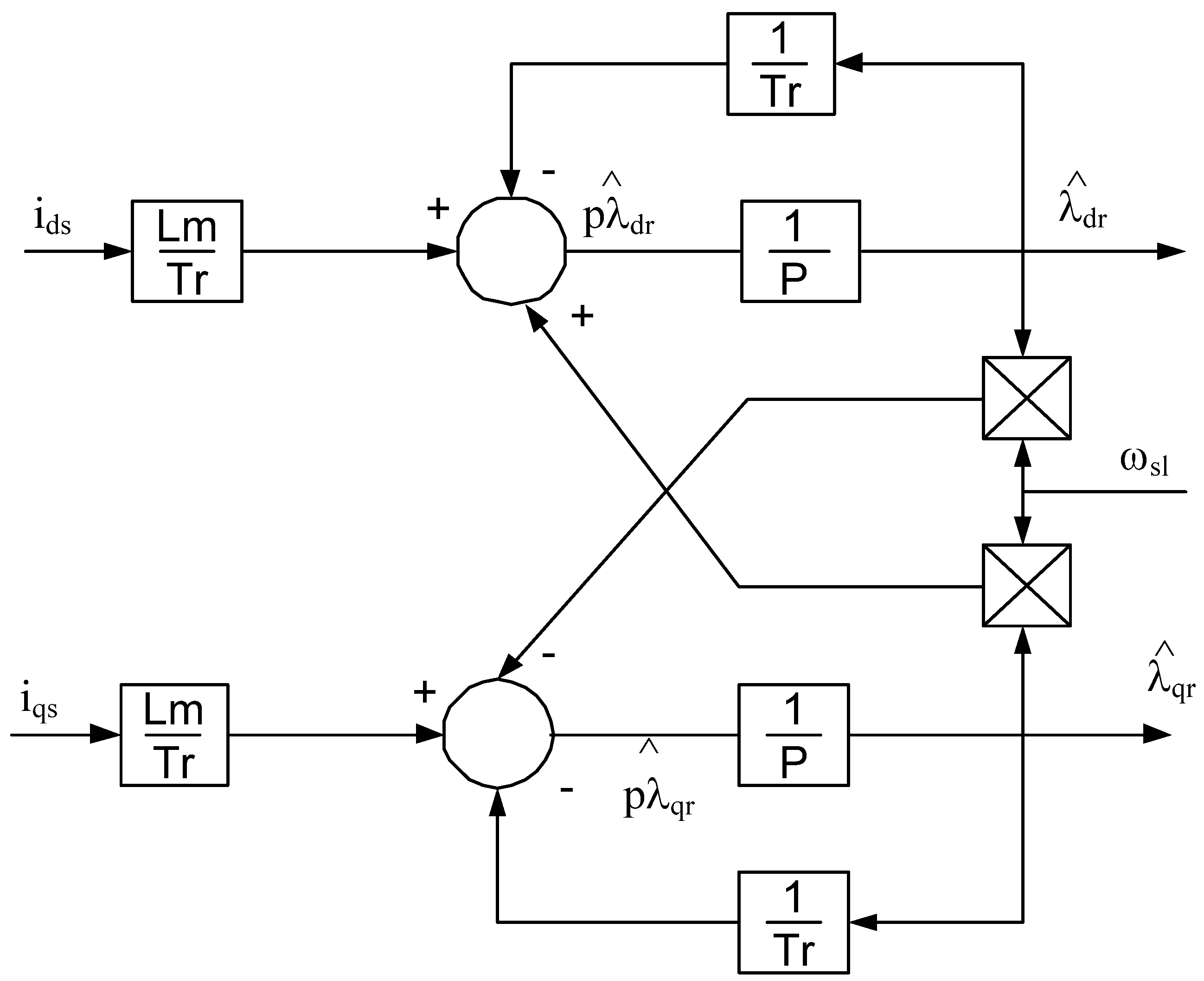
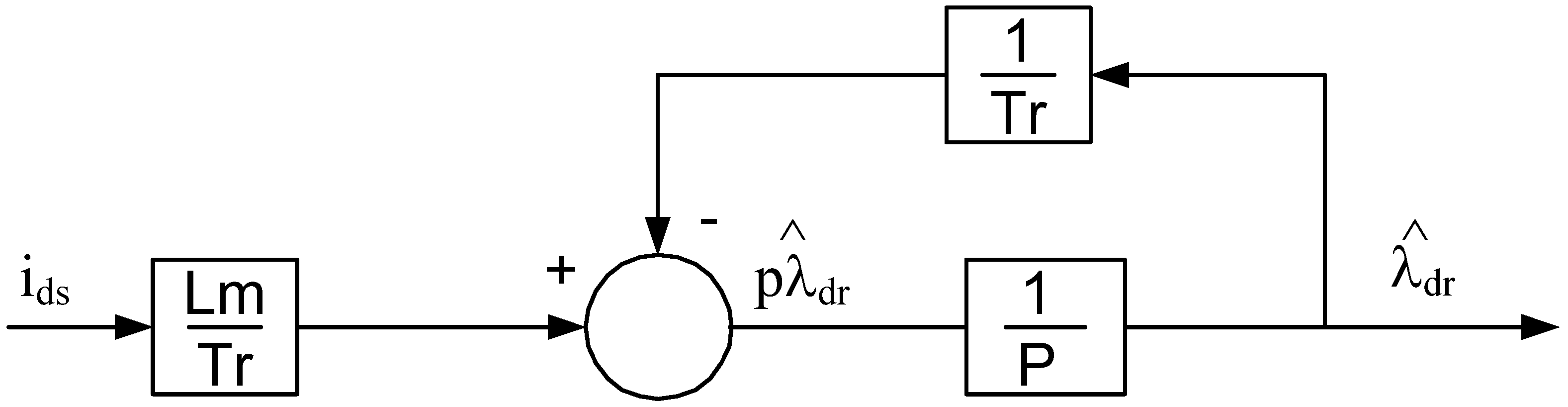
The model represented in Figure 11 [14] can estimate the rotor flux directly from the stator current, slip speed ωsl, rotor inductance Lr, and rotor resistance Rr. For an ideal rotor flux, regulated indirect field oriented machine the rotor flux along the q axis is zero, which reduces the block diagram given in Figure 11 to the one shown in Figure 12. The voltage and current model flux observers are commonly used in the stationary frame of reference for direct field orientation control, for sensorless control, or for the flux estimation and regulation of an indirect field oriented drive system. However, this work adopts a unique approach for using the current model flux observer. For an IFO drive system, the observer structure is designed in the synchronous frame of reference instead of the stationary frame of reference. Magnetizing inductance, rotor inductance, and rotor resistance are machine parameters in the current model flux observer presented in Equation (11). The magnetizing inductance (Lm) and rotor inductance (Lr) of the machine do not require an online adaptation because they don’t change with temperature variations. The leakage inductance of an induction machine is sensitive to the operating conditions of the machine; however, in contrast to the voltage model observer, no explicit knowledge of leakage inductance is required for the current model observer. The rotor resistance is the only parameter which changes with the machine’s temperature in the current model flux observer. This discussion leads to the proposed MRAS scheme, which is used for online rotor resistance adaptation. The idea to tune the rotor resistance is proposed as:
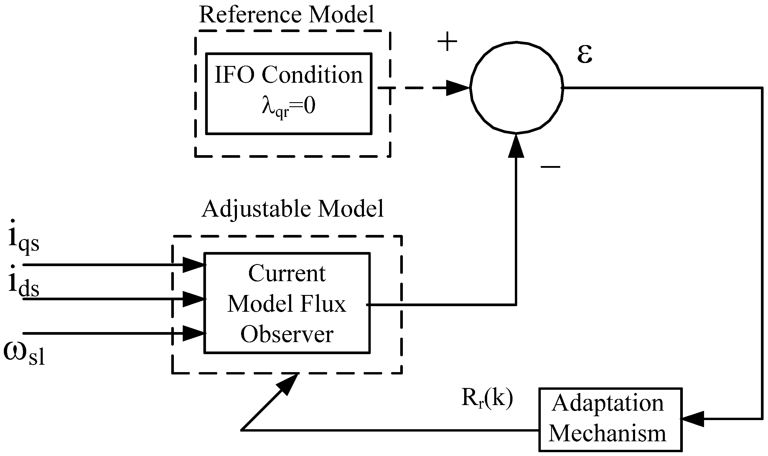
“The fact that the rotor flux along the q-axis is zero, i.e., is used as a reference model. Then the equation is used as an adjustable model. The adaptation mechanism adjusts the rotor resistance in the adjustable model such that it follows the reference model. As a result the rotor resistance is tuned to its correct value and is driven to zero”.
The proposed control algorithm is shown in Figure 13 [14]. The only unknown parameter in the adjustable model is Rr. If Rr is correct, then the flux calculated from the adjustable model will be equal to the reference model. When the temperature changes, Rr deviates from the original value, which then drives away from zero. This error in the flux will be forced back to zero by adjusting Rr, which will bring the rotor resistance to its actual value. The flux error equation can be written as where . A PI structure is used for the rotor resistance adaptation [14].
where
T is the sampling time of the adaptation mechanism.
Figure 11.
Current model rotor flux observer.

Figure 12.
A tuned current model rotor flux observer.

Figure 13.
MRAS structure for rotor resistance adaptation.

4. Simulation and Experimental Results for Online Rotor Resistance Adaptation
A simulation study was performed to validate the proposed algorithm. After intensive, multiple simulations testing, the proposed algorithm was validated on a 3.75 kW induction machine using the same test setup that was deployed for offline tuning. The machine parameters are shown in Table 2. The motor was started at an ambient temperature under the most practical applications. The nominal rotor resistance given in Table 2 is used as the initial value to start the controller. When the machine operates, its temperature varies which also changes the rotor resistance. The rotor resistance needs to be adjusted in the controller to keep the machine field oriented. The inductance programmed in the controller, based on the current and speed of the machine, does not change with temperature. If the rotor inductance is inaccurate, the algorithm will keep adjusting the rotor resistance until the rotor flux along q-axis becomes zero. Thus, the proposed technique also indirectly has the advantage of overcoming any problems that result from the inaccurate value of the rotor’s inductance.
| Machine | Values |
|---|---|
| Voltage | 220 V |
| Current | 14.8 A |
| Power | 3.75 kW |
| Stator and Rotor Inductance | Lls = Llr = 1.9 mH |
| Magnetizing Inductance | Lm = 41.2 mH |
| Rated Speed | 1670 rpm |
| Stator Resistance | Rs = 0.6 Ω |
| Rotor Resistance | Rr = 0.412 Ω |
| Pole | 4 poles |
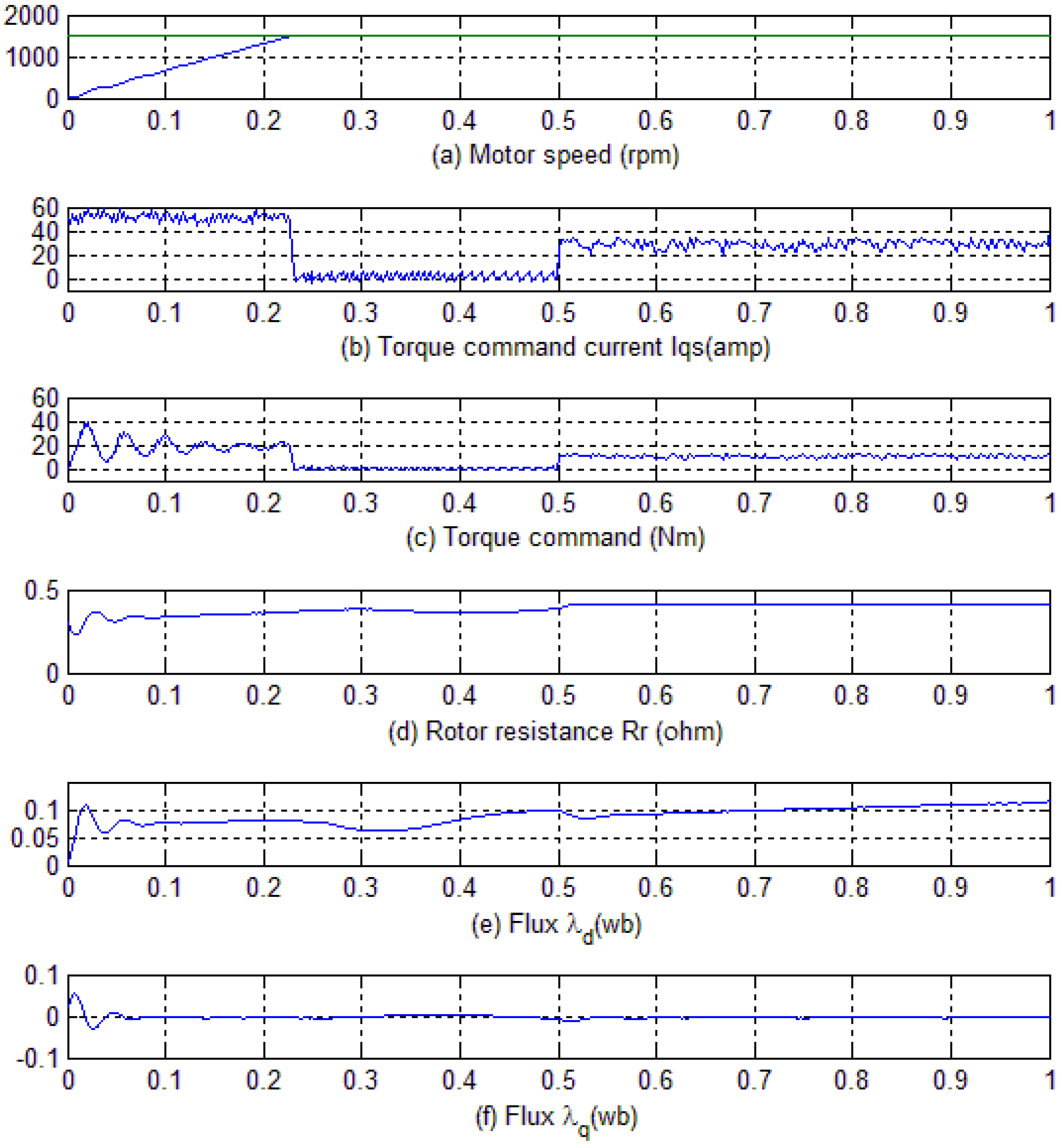
Simulation results for a command speed of 1500 rpm are shown in Figure 14. The command and actual speeds are plotted in Figure 14a while the Figure 14b,c respectively show the torque command current and corresponding torque command set by the field oriented controller to attain the desired speed. The rotor resistance is plotted in Figure 14d while the flux in the synchronous frame of reference along d and q axis are given in Figure 14e,f respectively. Additionally, at 0.5 s, a load of 10 Nm is applied on the machine. Initially, as can be observed in Figure 14b, motor applies the maximum allowable torque command current of 50 amp to bring the motor to the desired speed. Once the motor speed reaches the command speed the torque command current is reduced to a minimal value to keep the motor running at 1500 rpm. At 0.5 s, when the machine is loaded with a torque of 10 Nm, it can be seen that the controller can effectively respond to this external load and keep the machine running at 1500 rpm by applying a torque command current of 30 amps. The Figure 14d shows the proposed algorithm can tune the rotor resistance to its accurate value of 0.412 Ω while driving the flux d-axis to its steady state value as shown in Figure 14e, and flux along q-axis to zero as shown in Figure 14f.
Figure 14.
Simulation Results with command speed of 1500 rpm and 10 Nm load. (a) Motor speed; (b) Torque command current; (c)Torque command; (d) Rotor resistance; (e) Flux in the synchronous frame of reference along d-axis; (f) Flux in the synchronous frame of reference along q-axis.
Figure 14.
Simulation Results with command speed of 1500 rpm and 10 Nm load. (a) Motor speed; (b) Torque command current; (c)Torque command; (d) Rotor resistance; (e) Flux in the synchronous frame of reference along d-axis; (f) Flux in the synchronous frame of reference along q-axis.

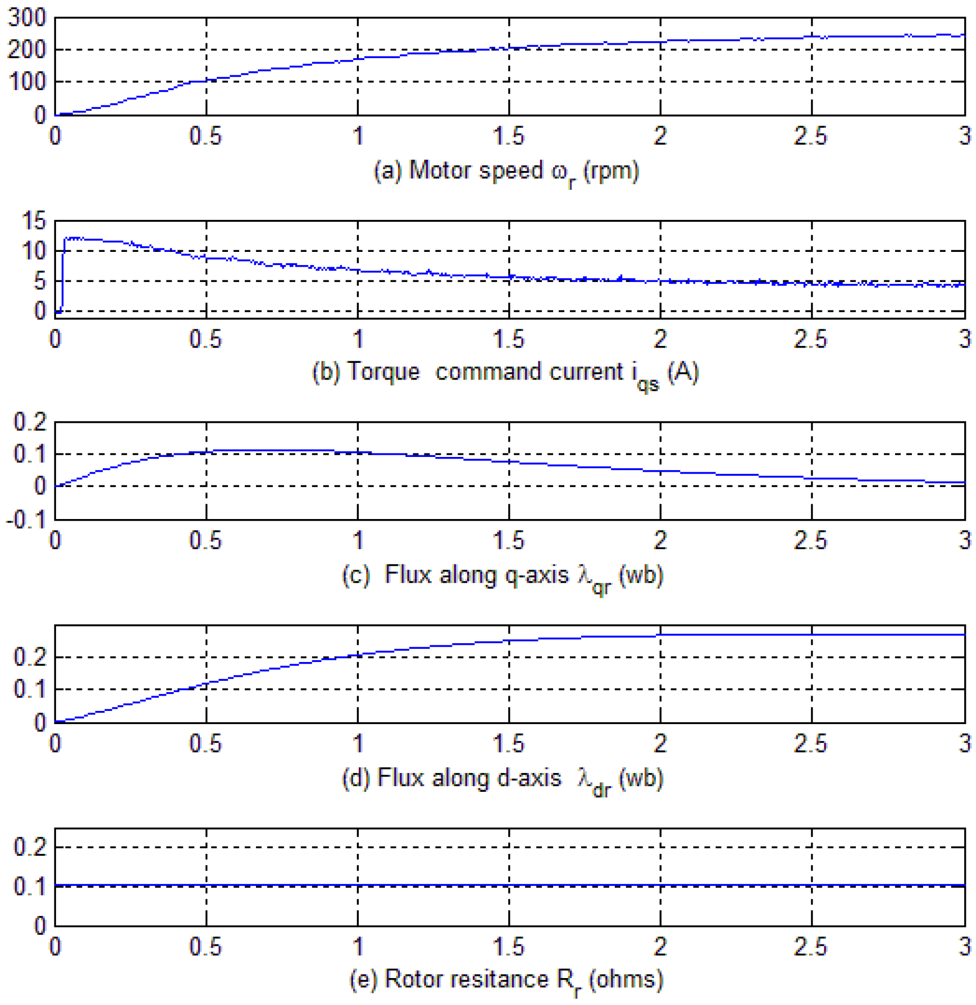
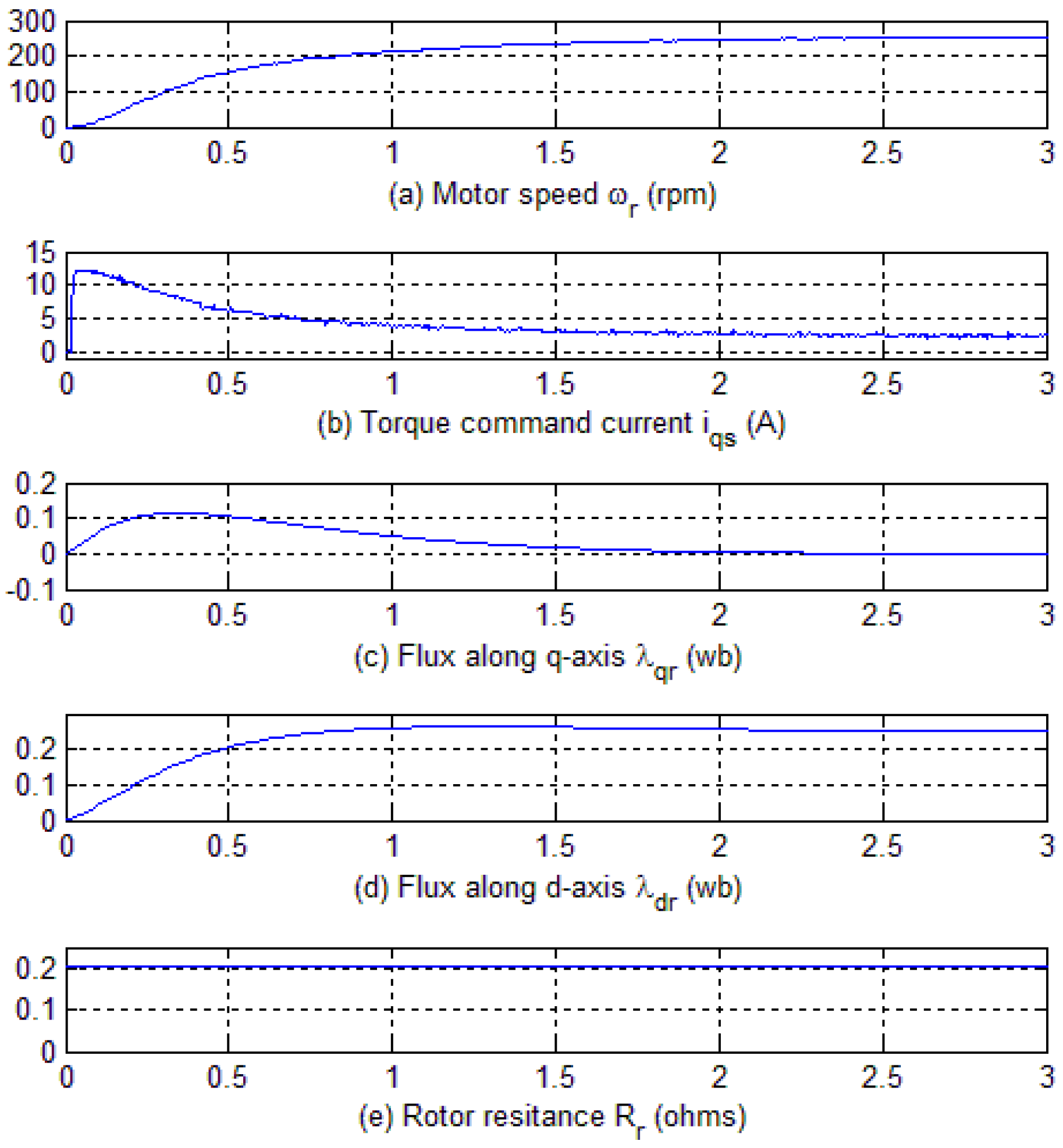
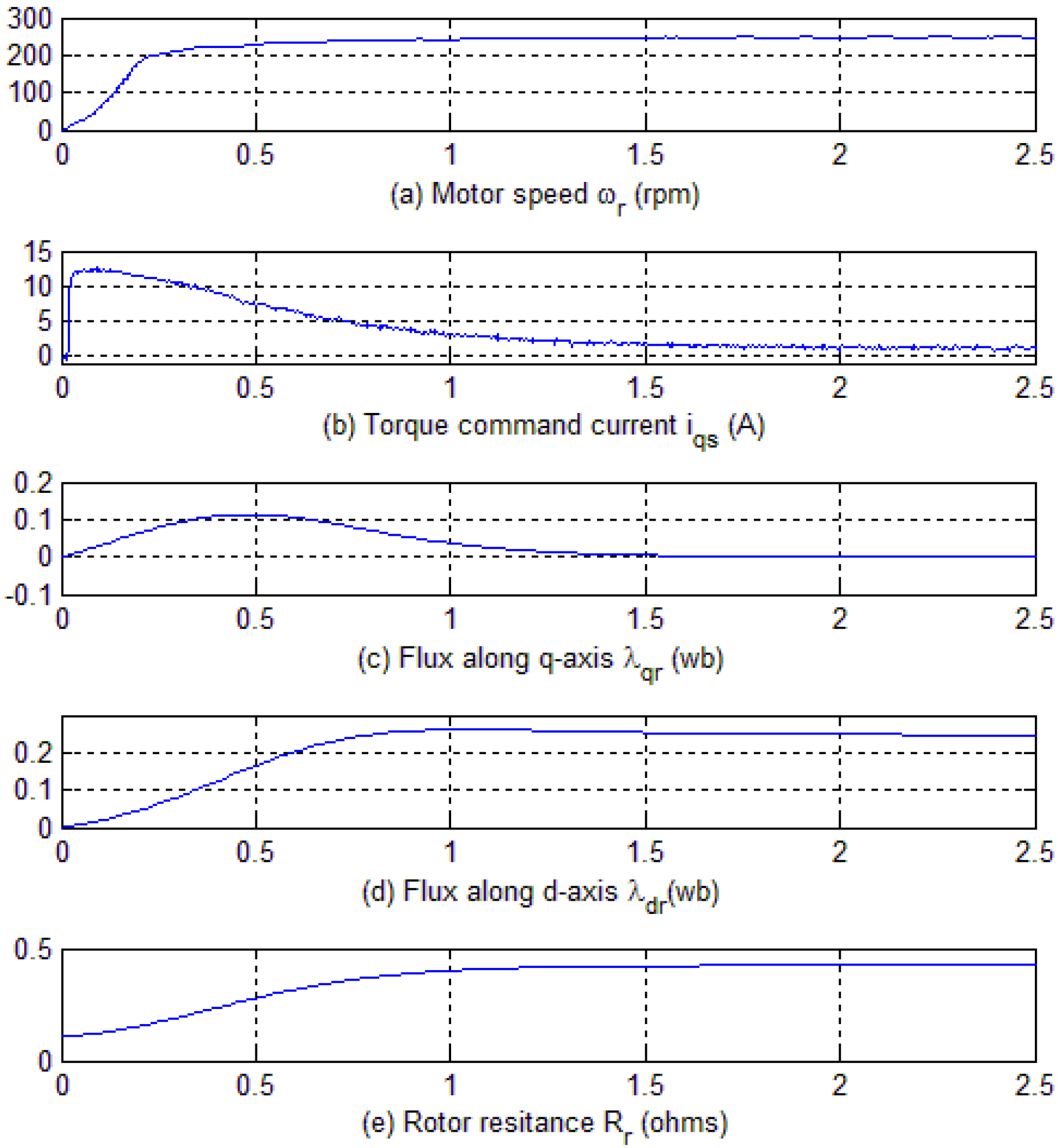
Finally, two types of experiments were performed to (i) investigate the effect of detuning on the machine’s performance; and to (ii) validate the effectiveness of the proposed algorithm for adjusting the rotor’s resistance to its accurate value. In these experiments, a step command of 250 rpm was applied and a PI controller was used to regulate speed. The flux level was kept fixed in all three cases with a fixed ids command input of 6 amps. The gains of the PI controller were kept the same to validate the effectiveness of the proposed scheme. The data under all three operating conditions were collected through the data acquisition capability of the Advanced Controller for Electric machines (ACE) [25]. The same hardware platform is used both in the vehicle testing and for the validation of online rotor resistance adaptation algorithm. The controller is fed with a wrong value of rotor resistance and no adaptation mechanism is applied to investigate the detuning effect. The controller is programmed with one fourth and one half of its actual value, which is 0.412 Ω at the ambient temperature. The results of these operating conditions are reported in Figure 15 and Figure 16 respectively. Finally, the rotor resistance is set to one fourth of its ambient value (0.412) and the proposed adaptation algorithm is applied to check its effectiveness. This scenario effectively ensures that the controller is commanded with a rotor resistance at a temperature much lower than the ambient temperature. The expected result is that the proposed MRAS scheme will tune the rotor resistance and adjust Tr to its correct value and keep the machine field oriented. The online rotor resistance adaptation technique is insensitive to temperature, when the temperature changes the rotor resistance will change, which will cause the rotor flux along q-axis to deviate from the reference value of zero. The proposed MRAS will then adjust the rotor resistance such that the flux along q-axis becomes zero. This has been proven by experimental result shown in Figure 17 where rotor resistance is fed by one fourth of its actual value (0.412) at the ambient temperature, meaning resistance of another temperature and the proposed MRAS did adjust the rotor resistance to its accurate value of 0.412. The experimental results for this case are plotted in Figure 17. In all the three Figure 15, Figure 16 and Figure 17, Figure a shows the motor actual speed, Figure b presents the torque command current set by the field oriented controller to attain the desired reference speed of 250 rpm. The Figure 15, Figure 16 and Figure 17c,d respectively show the flux along q and d axis in the synchronous frame of reference while the rotor resistance is given in Figure 15, Figure 16 and Figure 17e. Following are observations made from the experimental results:
- Figure 15, Figure 16 and Figure 17 trace (b) shows the actual current iqs for three different operating conditions. The current level of iqs is at a maximum in Figure 15; it decreases slightly in Figure 16 while it is at a minimum level in Figure 17. As stated above, Figure 15 presents the case in which the rotor resistance is set to one fourth of its value, and Figure 16 shows the results with rotor resistance set at one half of its value and when no adaptation is applied in either scenario. Figure 17 presents the case where, despite the rotor resistance being initialized with one fourth of its value, the MRAS adjusted the resistance to its accurate value, thus putting the machine into field orientation and requiring a minimal level of current for the same operating conditions as presented in Figure 15 and Figure 16. This proves that the proposed algorithm works effectively and increases the torque per amps output of the machine.
- The speed response under three different conditions is plotted in trace (a) of Figure 15, Figure 16 and Figure 17. It shows that the response is faster with adaptation, proving that the controller with the adaptation adjusts the resistance to its accurate value and hence keeps the machine field oriented, providing an instantaneous torque/speed response. Trace (c) and (d) of Figure 15, Figure 16 and Figure 17 show the estimated rotor fluxes, and , in the synchronous frame. and reach their steady state values faster with adaptation compared to when no adaptation is applied.
- The rotor resistance is plotted in trace (e) of Figure 15, Figure 16 and Figure 17. In Figure 15 and Figure 16, the rotor resistance remains at its pre-set value while trace (e) of Figure 17 demonstrates that the proposed adaptation mechanism has the ability to tune the rotor resistance to its actual value of 0.412 Ω.
Figure 15.
Experimental results with Rr/4 and no adaptation. (a) Motor speed in rpm; (b) Torque command current in synchronous frame of reference; (c) Flux along q-axis in synchronous frame of reference; (d) Flux along d-axis in synchronous frame of reference; (e) Rotor resistance.
Figure 15.
Experimental results with Rr/4 and no adaptation. (a) Motor speed in rpm; (b) Torque command current in synchronous frame of reference; (c) Flux along q-axis in synchronous frame of reference; (d) Flux along d-axis in synchronous frame of reference; (e) Rotor resistance.

Figure 16.
Experimental results with Rr/2 and no adaptation. (a) Motor speed in rpm; (b) Torque command current in synchronous frame of reference; (c) Flux along q-axis in synchronous frame of reference; (d) Flux along d-axis in synchronous frame of reference; (e) Rotor resistance.
Figure 16.
Experimental results with Rr/2 and no adaptation. (a) Motor speed in rpm; (b) Torque command current in synchronous frame of reference; (c) Flux along q-axis in synchronous frame of reference; (d) Flux along d-axis in synchronous frame of reference; (e) Rotor resistance.

Figure 17.
Experimental results with Rr/4 and adaptation. (a) Motor speed in rpm; (b) Torque command current in synchronous frame of reference; (c) Flux along q-axis in synchronous frame of reference; (d) Flux along d-axis in synchronous frame of reference; (e) Rotor resistance.
Figure 17.
Experimental results with Rr/4 and adaptation. (a) Motor speed in rpm; (b) Torque command current in synchronous frame of reference; (c) Flux along q-axis in synchronous frame of reference; (d) Flux along d-axis in synchronous frame of reference; (e) Rotor resistance.

5. Conclusions
This paper proposes an off-line and another online technique to overcome the detuning for improving the performance of vehicular drive system. The performance of off-line scheme is validated for the drive system of a test vehicle while the online scheme is tested on a prototype induction motor in the lab. Both techniques can effectively tune the rotor resistance to its correct value, and keep the machine field-oriented. The following are major conclusions drawn from this work:
- The off-line technique pre-sets the rotor resistance for different operating conditions. It needs intensive testing to program the controller with the correct value of the rotor resistance at various operating conditions. Therefore, it becomes motor-specific and cannot be used for an off-the-shelf machine. The online technique performs better because it does not require the machine to be pre-tested and can work for any machine under any operating condition.
- The proposed online rotor resistance adaptation technique is simpler compared to the ones presented in the past and is better than using techniques that incorporate intelligent controllers for overcoming the detuning problem. Even though intelligent controllers provide a better torque response, they do not fix the rotor resistance to its accurate value resulting into lesser torque per amps.
Conflicts of Interest
The authors declares no conflict of interest.
References
- Blaschke, F. A New Method for Structural Decoupling of A.C. Induction Machines. In Proceedings of the Conference Rec. IFAC, Duesseldorf, Germany, 11–13 October 1971.
- Takahashi, I.; Noguchi, T. A New Quick Response and High Efficiency Control Strategy for an Induction Motor. IEEE Trans. Ind. Appl. 1985, IA-22, 820–827. [Google Scholar] [CrossRef]
- Rehman, H.; Xu, L. Alternative energy vehicles drive system: Control, flux and torque estimation, and efficiency optimization. IEEE Trans. Veh. Technol. 2011, 60, 3625–3634. [Google Scholar] [CrossRef]
- Rodriguez, J.; Kennel, R.M.; Espinoza, J.R.; Trincado, M.; Silva, C.A.; Rojas, C.A. High performance control strategies for electrical drives: an experimental assessment. IEEE Trans. Ind. Electron. 2012, 59, 812–820. [Google Scholar] [CrossRef]
- Brooks, L.A.; Castro, J.L.; Castro, E.L. Speed and position controller using indirect filed-oriented control: A classical control approach. IEEE Trans. Ind. Electron. 2014, 61, 1928–1943. [Google Scholar] [CrossRef]
- Rehman, H. An integrated starter alternator and low cost, high performance drive for vehicular applications. IEEE Trans. Veh. Technol. 2008, 57, 1454–1465. [Google Scholar] [CrossRef]
- Sung, W.; Shin, J.; Jeong, Y. An energy-efficient and robust control for high-performance induction motor drive with an application in electric vehicles. IEEE Trans. Veh. Technol. 2012, 61, 3394–3405. [Google Scholar] [CrossRef]
- Uddin, M.N.; Wen, H. Development of a self-tuned neuro fuzzy logic controller for induction motor drive. IEEE Trans. Ind. Appl. 2007, 47, 1108–1116. [Google Scholar] [CrossRef]
- Zhen, L.; Xu, L. Fuzzy learning enhanced speed control of an indirect field oriented induction machine drive. IEEE Trans. Control Syst. Technol. 2000, 8, 270–278. [Google Scholar] [CrossRef]
- Masiala, M.; Vafakhah, B.; Salmon, J.; Knight, A.M. Fuzzy self-tuning speed control of an indirect field-oriented control induction motor drive. IEEE Trans. Ind. Appl. 2008, 44, 1732–1740. [Google Scholar] [CrossRef]
- Uddin, M.N.; Zhi, R.H.; Hossain, A.B.M.S. Development and implementation of a simplified self-tuned neuro-fuzzy-based IM drive. IEEE Trans. Ind. Appl. 2014, 50, 51–59. [Google Scholar] [CrossRef]
- Zaho, L.; Jin, H.; Liu, H.; Li, B.; Kong, W. Second-order sliding-mode observer with online parameter identification for sensorless induction motor drives. IEEE Trans. Ind. Electron. 2014, 61, 5280–5289. [Google Scholar]
- Chen, B.; Yao, W.; Chen, F.; Lu, Z. Parameter sensitivity in sensorless induction motor drives with the adaptive full-order observer. IEEE Trans. Ind. Electron. 2015, 62, 4307–4318. [Google Scholar] [CrossRef]
- Rehman, H.; Derdiyok, A.; Guven, M.K.; Xu, L. An MRAS Scheme for the On-Line Rotor Resistance Adaptation of Induction Machine. In Proceedings of the 32nd IEEE Power Electronics Specialists Conference, Vancouver, BC, Canada, 17–21 June 2001.
- Rehman, H. Detuning Minimization of Alternative Energy Vehicular Drive System. In Proceedings of the IEEE Vehicle Power and Propulsion Conference, Seoul, Korea, 9–12 October 2012.
- Toliyat, H.A.; Levi, E.; Raina, M. A review of RFO induction motor parameter estimation techniques. IEEE Trans. Energy Convers. 2003, 18, 271–283. [Google Scholar] [CrossRef]
- Karanayil, B.; Rahman, M.F.; Grantham, C. Online stator and rotor resistance estimation scheme using artificial neural networks for vector controlled speed sensorless induction motor drive. IEEE Trans. Ind. Electron. 2007, 54, 167–176. [Google Scholar] [CrossRef]
- Hassan, S.M.N.; Hassan, I. A luenberger-sliding mode observer for online parameter estimation and adaptation in high-performance induction motor drives. IEEE Trans. Ind. Appl. 2009, 45, 772–781. [Google Scholar] [CrossRef]
- Rao, S.; Buss, M.; Utkin, V. Simultaneous state and parameter estimation in induction motors using first- and second-order sliding modes. IEEE Trans. Ind. Electron. 2009, 56, 3369–3376. [Google Scholar] [CrossRef]
- Kenne, G.; Simo, R.S.; Lamnabhi-Lagarrigue, F.; Arzande, A.; Vannier, J.C. An online simplified rotor resistance estimator for induction motors. IEEE Trans. Control Syst. Technol. 2010, 18, 1188–1194. [Google Scholar] [CrossRef]
- Dehbozorgi, M.R.; Kojabadi, H.M.; Vahedi, H.; Al-haddad, K. A Comparative Study of Various MRAS-based IM’s Rotor Resistance Adaptation Methods. In Proceedings of the IEEE Industrial Electronics Conference (IECON), Montreal, QC, Canada, 25–28 October 2012.
- Yoo, A.; Hong, C.; Ha, J. On-Line Rotor Time Constant Estimation for Indirect Field Oriented Induction Machine. In Proceedings of the IEEE Energy Conversion Congress and Exposition (ECCE), Denver, CO, USA, 15–19 September 2013.
- Terras, T.; Hadjeri, S.; Mezouar, A.; Chikouche, T.M. Robust speed control with rotor resistance estimation. Can. J. Electr. Comput. Eng. 2013, 36, 43–51. [Google Scholar] [CrossRef]
- Krause, P.C.; Wasynczuk, O.; Sudhoff, S.D. Analysis of Electric Machinery and Drives Systems; Wiley-IEEE Press: Hoboken, NJ, USA, 2013. [Google Scholar]
- Rehman, H.; Hampo, R.J. A Flexible High Performance Advanced Controller for Electric Machines. In Proceedings of the IEEE APEC 2000 Conference Record, New Orleans, LA, USA, 6–10 February 2000; pp. 939–943.
© 2015 by the authors; licensee MDPI, Basel, Switzerland. This article is an open access article distributed under the terms and conditions of the Creative Commons Attribution license (http://creativecommons.org/licenses/by/4.0/).
Share and Cite
MDPI and ACS Style
Rehman, H. Detuning Minimization of Induction Motor Drive System for Alternative Energy Vehicles. Energies 2015, 8, 9117-9136. https://doi.org/10.3390/en8099117
AMA Style
Rehman H. Detuning Minimization of Induction Motor Drive System for Alternative Energy Vehicles. Energies. 2015; 8(9):9117-9136. https://doi.org/10.3390/en8099117
Chicago/Turabian StyleRehman, Habibur. 2015. "Detuning Minimization of Induction Motor Drive System for Alternative Energy Vehicles" Energies 8, no. 9: 9117-9136. https://doi.org/10.3390/en8099117