Article

A Novel Pitch Control System of a Large Wind Turbine Using Two-Degree-of-Freedom Motion Control with Feedback Linearization Control

Department of Engineering Science and Ocean Engineering, National Taiwan University, No. 1, Sec. 4, Roosevelt Rd., Taipei 106, Taiwan
*
Author to whom correspondence should be addressed.
Energies 2016, 9(10), 791; https://doi.org/10.3390/en9100791
Submission received: 13 July 2016 / Revised: 9 September 2016 / Accepted: 20 September 2016 / Published: 29 September 2016
(This article belongs to the Collection Wind Turbines)

Abstract

:
Pitch Control plays a significant role for a large wind turbine. This study investigates a novel robust hydraulic pitch control system of a large wind turbine. The novel hydraulic pitch control system is driven by a novel high efficiency and high response hydraulic servo system. The pitch controller, designed by two degree-of-freedom (2-DOF) motion control with feedback linearization, is developed to enhance the controllability and stability of the pitch control system. Furthermore, the full-scale testbed of the hydraulic pitch control system of a large wind turbine is developed for practically experimental verification. Besides, the wind turbine simulation software FAST is used to analyze the motion of the blade which results are given to the testbed as the disturbance load command. The 2-DOF pitch controller contains a feedforward controller with feedback linearization theory to overcome the nonlinearities of the system and a feedback controller to improve the system robustness for achieving the disturbance rejection. Consequently, the novel hydraulic pitch control system shows excellent path tracking performance in the experiments. Moreover, the robustness test with a simulated disturbance load generated by FAST is performed to validate the reliability of the proposed pitch control system.

1. Introduction

Wind energy has become one of the most important renewable energies due to the increasing consumption of fossil energy and the technological advancements in generating power. Therefore, the applications of modern wind energy have not only expanded in recent year, but also been considered as a substitution for nuclear energy in many countries. Besides, the global development of wind farm also emphasizes the importance of large wind turbines.
Modern large wind turbines can be divided into three different types: constant speed, variable pitch control, and variable speed types. A simple strategy with stall control and fixed blade was developed in 1988 [1]. System identification of the dynamic model of wind turbine with experiments was investigated [2]. Subsequently, modeling for the variable speed wind turbine started in the 2000s [3]. In order to extract the optimal power for a wind turbine, torque control was developed, which is also known as region 2 control strategies [4,5,6]. For region 3 control, pitch control is activated to maintain the maximum output power. Other investigations of how to maintain the output power of the variable speed wind turbine were implemented afterward [7]. The variable speed wind turbine was realized by using robust control [8]. The nonlinear and adaptive control were studied and applied to the variable pitch control for variable speed wind turbine [9]. Besides, the nonlinear control of variable speed wind turbines without wind speed measurement was discussed [10]. The digital robust control of a wind turbine for the rated-speed and the variable-power operation regime were also developed [11]. Nowadays, the size and power of wind turbine have been grown up to multi-megawatt level [12].
In the Asian countries, which usually suffer from Typhoons and turbulent wind, pitch control type is more appropriate. Through controlling the variable pitch angle of blades, the rotational speed of the wind turbine can be kept to generate rated electric power. Several pitch control strategies have been studied since 2001 [13]. Some advanced pitch control strategies, such as a hybrid controller for all operating regions of wind turbine, were investigated and developed [14]. Furthermore, the reduction of aerodynamic loading releases the torque on rotor shaft, which also prevents the rotor from shutdown, can also reduce the loads on the turbine tower [15]. All these prove the importance of pitch control in the wind turbine. The pitch driving system of wind turbines can be classified into electrical motor driving and hydraulic driving systems. Comparing with electrical motor driving system, hydraulic driving system not only replaces the gear sets to avoid the serious erosion but also enhance the robustness due to the hydraulic cylinder driven mechanism. However, some difficulties such as lower efficiency and higher nonlinearity problems should not be neglected in hydraulic devices. For the wind turbine, there are several kinds of integral challenges should be taken into consideration including both mechanical part and electrical part. For mechanical part, the delay and synthesis problem may have influences on the pitch system [16,17]. On the other hand, the electrical part such as power grid is another important issue [18].
Recently, high response and high energy efficiency hydraulic systems were proposed [19], which involved an electric-hydrostatic driven system with an AC servo motor and a constant displacement internal gear pump for power-saving motion control. Further, the differences of the electro-hydraulic actuator by using gear pump and electromotor were investigated [20]. Therefore, this study proposes a new hydraulic servo system with an AC servo motor and a constant displacement hydraulic piston pump for achieving both high response and high energy efficiency.
Furthermore, a pitch controller should be designed to implement the novel pitch control system. Several control theories have been used in hydraulic system. For instance, fuzzy control was used in the positioning control of the hydraulic pump-controlled system with variable rotational speed. Adaptive fuzzy controller with self-tuning fuzzy sliding-mode compensation controller was investigated to enhance the position control performance [21,22]. However, a model-based controller usually needs to simplify the nonlinear models so that it is still difficult to be applied in hydraulic systems, especially in wind turbine system due to the high nonlinearity and the difficulty for obtaining the exact model and parameters of hydraulic systems. Therefore, a feedback linearization controller is proposed in this study to solve this problem.
Linearization is one of the most fundamental and effective methods in nonlinear systems, and has played an important role in nonlinear control system theory [23]. The main concept of feedback linearization problem is to transform the nonlinear system into a linear system by designing an appropriate control signal based on system model and tracking target. Brockett [24] has verified and solved for single input case ( m = 1 ), while the general case ( m 1 ) of feedback linearization problem has been solved by Jakubczyk et al. [25]. Subsequently, this theory was applied to a hydraulic servo system [26,27].
The novel hydraulic pitch control system is a motion control system so that two degree-of-freedom (2-DOF) controller design can be used. To fulfill short motion time and small settling times, a standard 2-DOF controller structure composed of feedback and feedforward theories was proposed [28]. The feedback controller enhances the stability and robustness while the feedforward controller improves the performance of tracking control. Devasia [29] introduced a robust inversion-based feedforward controller for tracking performance in 2000. Thus, plant inversion was discussed to make higher performance such as Torfs [30] released a comparison of two feedforward design in 1998.
Therefore, the novel hydraulic pitch controlled system of large wind turbines, which contains two differential cylinders, the high response hydraulic pump-controlled system with an AC servo motor, and the pitch controller designed by 2-DOF motion control, are investigated in this study. However, the researches on the hydraulic servo driving pitch control system combining with the hardware-in-the-loop analysis for large wind turbines are still rare. Based on the previous study [21,22], this study improved the testbed from two different aspects: the commercial product for wind turbine controller is usually equipped with simple micro controller. It is important to reduce the computing time when the proposed idea is going to realize to a real wind turbine. The new designed 2-DOF motion controller that has been developed in this study had a great improvement on reducing the computing time when comparing with previous intelligent controller. What’s more, this study also takes the more practical disturbance by integrating the wind turbine simulator “FAST”. The disturbance profile can be presented as a function of pitch angle and wind speed. Thus, the experiment can be achieved and implemented with a more convincing disturbance profile to guarantee the robustness of this pitch control system.
Thus, a standard 2-DOF controller with feedback and feedforward controller is developed as the pitch controller. Meanwhile, the dynamic performance will be examined by specific disturbances calculated by turbine simulation software FAST [31]. With the help of FAST, the resultant and reacting torque at the blade root caused by aerodynamic force of blade under different wind input can be extracted by this software, and then given to the disturbance system of the test rig. Finally, the developed novel pitch control system controlled by the robust 2-DOF controller will be realized and verified for the pitch path tracking control and path-positioning control by practical experiments in the full-scale testbed under different path profiles, load torques, and wind speed.

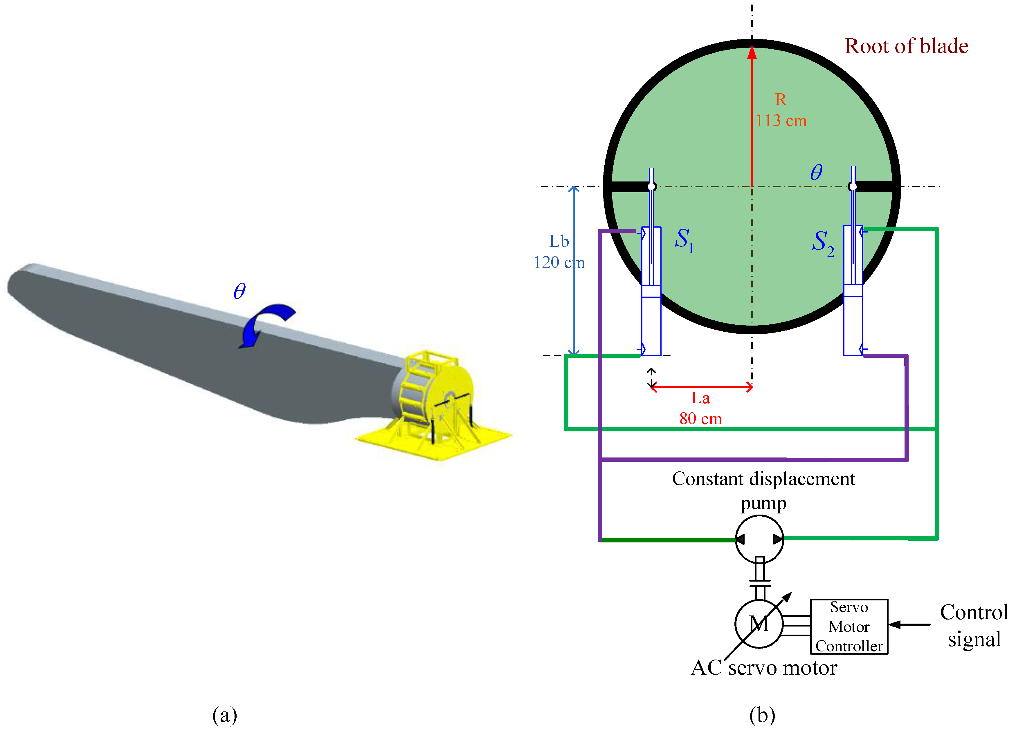
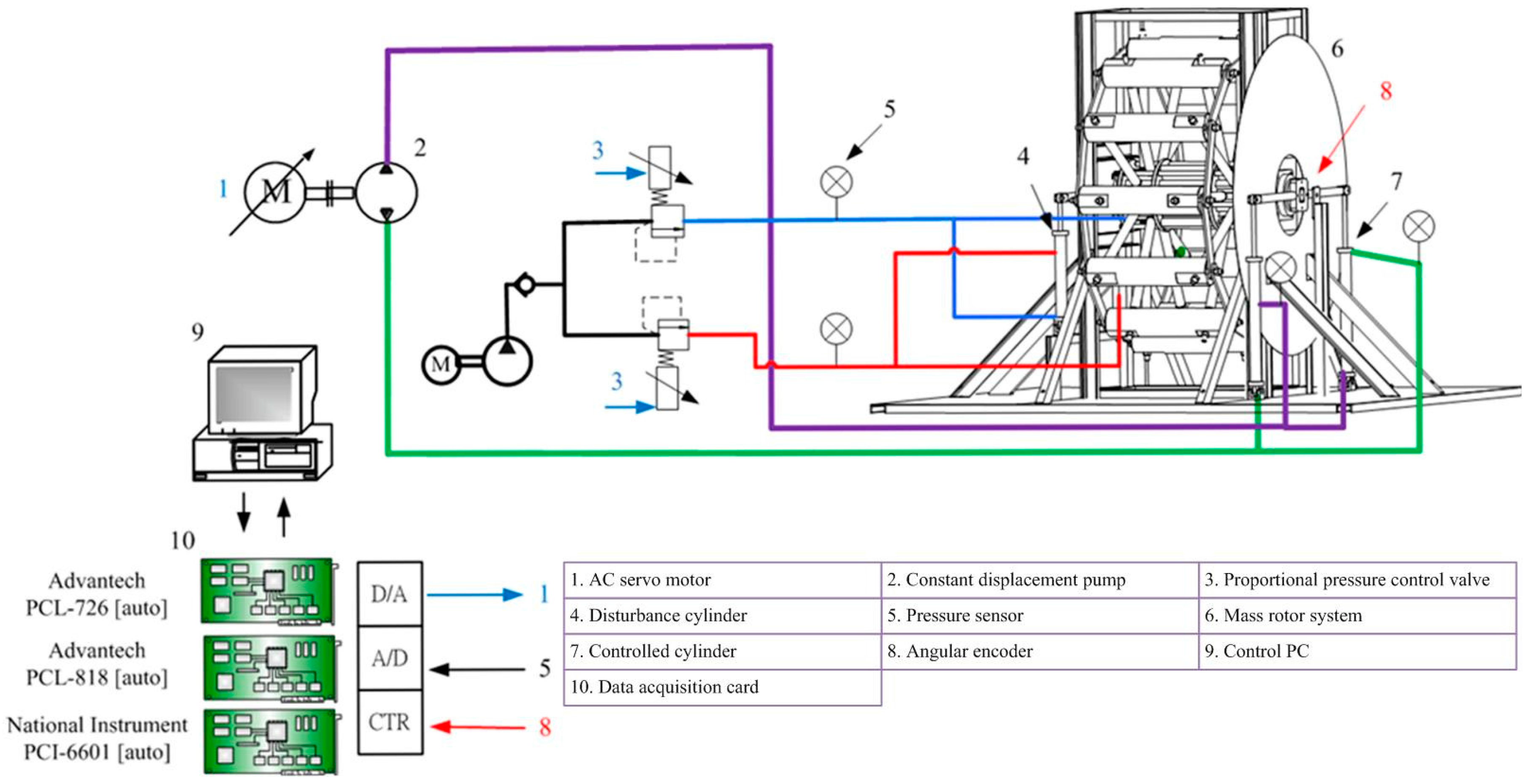
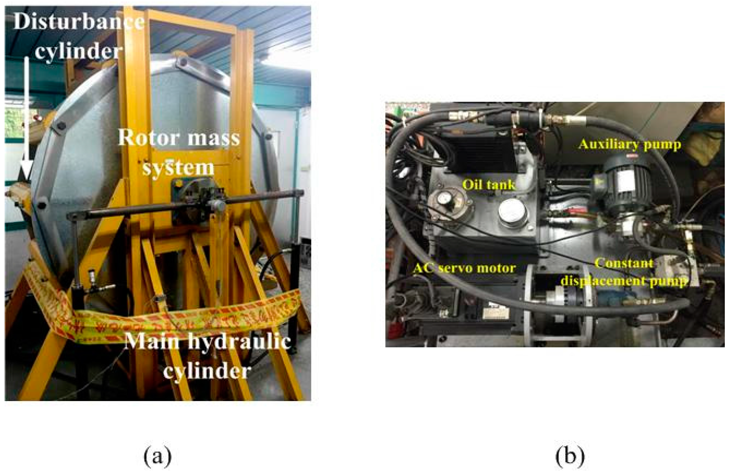
2. Test Rig of Novel Hydraulic Pitch Control System

This paper proposes the novel hydraulic pitch control system of wind turbine driven by a variable rotational speed electro-hydraulic pump-controlled system with an AC servo motor, as shown in Figure 1, which consists of two differential cylinders controlled by a variable rotational speed hydraulic pump-controlled system. The two hydraulic cylinders are located at the root of a blade. The variable rotational speed hydraulic pump-controlled system contains an AC servo motor and a constant displacement piston pump. Due to the closed hydraulic pump-controlled circuit, the inlet and outlet volume flow of the pump must be the same. In this paper, the hydraulic circuits between pump and the two differential cylinders are designed as shown in Figure 1b. By connecting the oil hoses from the pump to the opposite sides of the two cylinders, the resultant piston area then becomes the same for the inlet and outlet of pump. In addition, the torque, generated by the two cylinders to drive the pitch angle motion, is a force couple and can be summed up. Thus, the size of the two differential hydraulic cylinders can be smaller than that driven by only one cylinder.
In order to implement a full-scale experimental analysis of the hydraulic pitch control system for a blade of a 2 MW wind turbine, the test rig of the full-scale hydraulic pitch control system of a 2 MW wind turbine blade driven by a variable rotational speed hydraulic pump-controlled system is set up, as shown in Figure 2. The specifications of the main components are listed in Table 1.
Figure 2 is the test rig of hydraulic pump-controlled pitch system. The rotor mass system, which is designed in accordance with the blade of the 2 MW wind turbine serves to simulate its dynamic characteristics so that the rotor mass denotes 2050 kgw and its moment of inertia indicates 1238 kg·m2 The disturbance system consists of two hydraulic cylinders and two proportional pressure control valves for adjusting the loading torque that is calculated in the simulation software FAST according to the wind speed. The PC-based control system performs the control strategy and the data acquisition. Therefore, the experimental system of pitch control can be implemented for analyzing the performance of the pitch control system of the large wind turbine under distinct wind speed conditions. The photograph of the test rig of hydraulic pitch control system is show as Figure 3.

3. Modeling of Novel Hydraulic Pitch Control System

The mathematic models of variable rotational speed hydraulic pump-controlled system are derived in Section 3.1. The mechanism of pitch control system and the overall system model transformed into state space equations for controller design are discussed in Section 3.2. The modeling of disturbance is described in Section 3.3.

3.1. Modeling of Hydraulic Pump-Controlled System

The variable rotational speed hydraulic pump-controlled system is driven by an AC servo motor motivating a constant displacement piston pump. The controller provided the control signals to regulate the rotational speed of the AC servo motor, and thus the flow rate of pump can be altered by varying input signals. The bandwidth of the AC servo motor is higher than hydraulic system, so its model can be considered as proportional units. The volume flow equation of the constant displacement pump is:
Q l = D l ω C l P l ,
where D l denotes the pump displacement; C l indicates the pump leakage coefficient; P l is the load pressure; ω is the rotational speed of AC servo motor. The relationship between the input signals and the rotational speed of AC servo motor is:
ω = K a u ,
where K a is a gain of rotational speed for AC servo motor; u is the input signal. Then the continuity equation of hydraulic cylinder can be described as:
Q l = A e x ˙ + C t P l + ( V / 4 β ) P ˙ l ,
where A e is the piston area; x ˙ is the cylinder velocity; C t is the leakage coefficient of cylinder; V is the compressed volume; β is the effective bulk modulus. Then, a function of continuity equation of load pressure in this pump controlled system can be obtained by combining Equation (1) with Equation (3):
D l ω = A e x ˙ + ( C l + C t ) P l + ( V / 4 β ) P ˙ l ,
Finally, this load pressure will push the cylinder rod to drive the blade, here a rotor mass system is replaced, which can be equivalent to a function of Newton’s second law of motion. The motion equation of hydraulic cylinder is shown in Equation (5):
f h f l = A e P l f l = M x ¨ + B x ˙ + K x ,
where x is the cylinder position; f h is the cylinder force; f l is the loading force; M is the mass; B is the damping ratio; K is the stiffness coefficient.

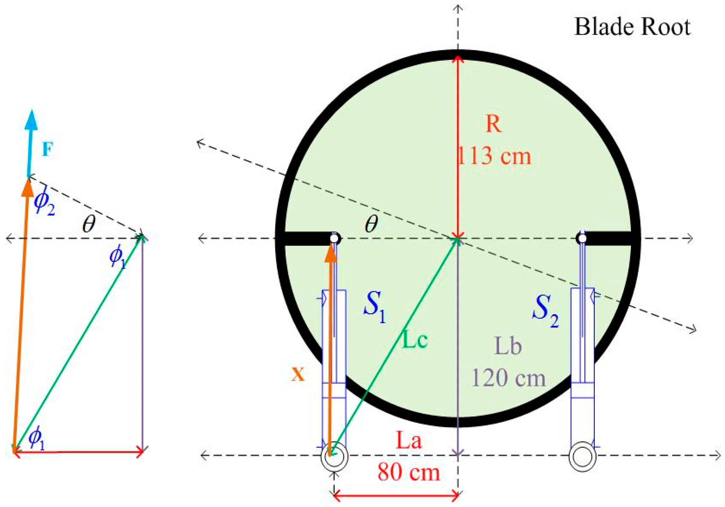
3.2. The Mechanism of the Hydraulic Pitch Control System

Since the pitch control of the blade is rotational motion, the linear motion equation of hydraulic cylinder in Equation (5) should be transformed into rotational motion equation of blade in accordance with the mechanism. The rotational motion equation of the rotor mass system, which has similar mass and moment of inertia of a blade, is:
T h = R × f h = A P   P l   L c sin ϕ 2 ,
where R is the equivalent force arm. In order to define specific angle ϕ 1 and ϕ 2 , the geometric relationships of mechanism can be expressed as Figure 4. Finally, a set of equations can be derived from Figure 4 to show the relations between specific angle and pitch angle:
ϕ 1 = tan 1 ( L b / L a ) ,
X 2 = L a 2 + L c 2 2 L a L c cos ( ϕ 1 + θ ) ,
ϕ 2 = cos 1 [ ( L a 2 + X 2 L c 2 ) / ( 2 L a X ) ] ,
X 2 = L a 2 + L c 2 2 L a L c cos ( ϕ 1 + θ ) ,
X / sin ( ϕ 1 + θ ) = L c / sin ( ϕ 2 ) ,
where X is the total length of hydraulic cylinder from the end of the cylinder chamber; R b is the radius of a blade root; L a ,   L b ,   L c are the length of mechanisms.
Finally, the overall system equation can be summarized as state equation as follows:
D l ω C l P l = A e X ˙ + C t P l + ( V / 4 β ) P ˙ l A e P l R sin ϕ 2 = J θ ¨ + D θ ˙ + C θ ,
where J is the moment inertia of rotor mass system; D is the damping coefficient; C is the stiffness coefficient. Through transforming Equation (13), the state equations of the variable rotational speed hydraulic pump-controlled system can be achieved:
x ˙ 1 = x 2 ( t ) x ˙ 2 = x 3 ( t ) x ˙ 3 = 1 3 a i x i ( t ) + g ( x _ ) u + d ( x _ ) = f ( x _ ) + g ( x _ ) u + d ( x _ ) ,
x _ = [ x 1 ( t ) x 2 ( t ) x 3 ( t ) ] T = [ θ ( t ) θ ˙ ( t ) P l ( t ) ] T ,
x ˙ 1 = x 2 x ˙ 2 = D J x 2 C J x 1 + A e R J L c sin ( ϕ 1 + x 1 ) R 2 + L c 2 2 L a L c cos ( ϕ 1 + x 1 ) x 3 x ˙ 3 = 4 β A e V L a L c sin ( ϕ 1 + x 1 ) x ˙ 1 R 2 + L c 2 2 L a L c cos ( ϕ 1 + x 1 ) 4 β C e V x 3 + 4 β V D e u y = x 1 ,

3.3. Modeling of Disturbance System

The loading torques of a wind turbine blade under different pitch angles and wind speeds can be calculated by using computational fluid dynamics (CFD) software AeroDyn integrated in the software FAST (Golden, CO, USA). In order to derive the model of the disturbance system, the resultant loading torques at the blade roots are extracted via FAST where the turbine model is established based on a practical 2 MW wind turbine installed in Taiwan. Table 2, which lists the loading torques of the wind turbine blade under different pitch angles and wind speeds, can be formulated as Equation (16) through curve fitting.
T d = 390 + 170.9 v w 92.96 θ 0.39 v w 2 0.24 v w θ 3.73 θ 2 ,
where T d is the loading torque, v w denotes the input wind speed. If a desired trajectory of pitch angle and the wind speed v w are given, the loading torque T can be obtained according to Equation (16), and will be given to the disturbance system of the test rig in the experiment.

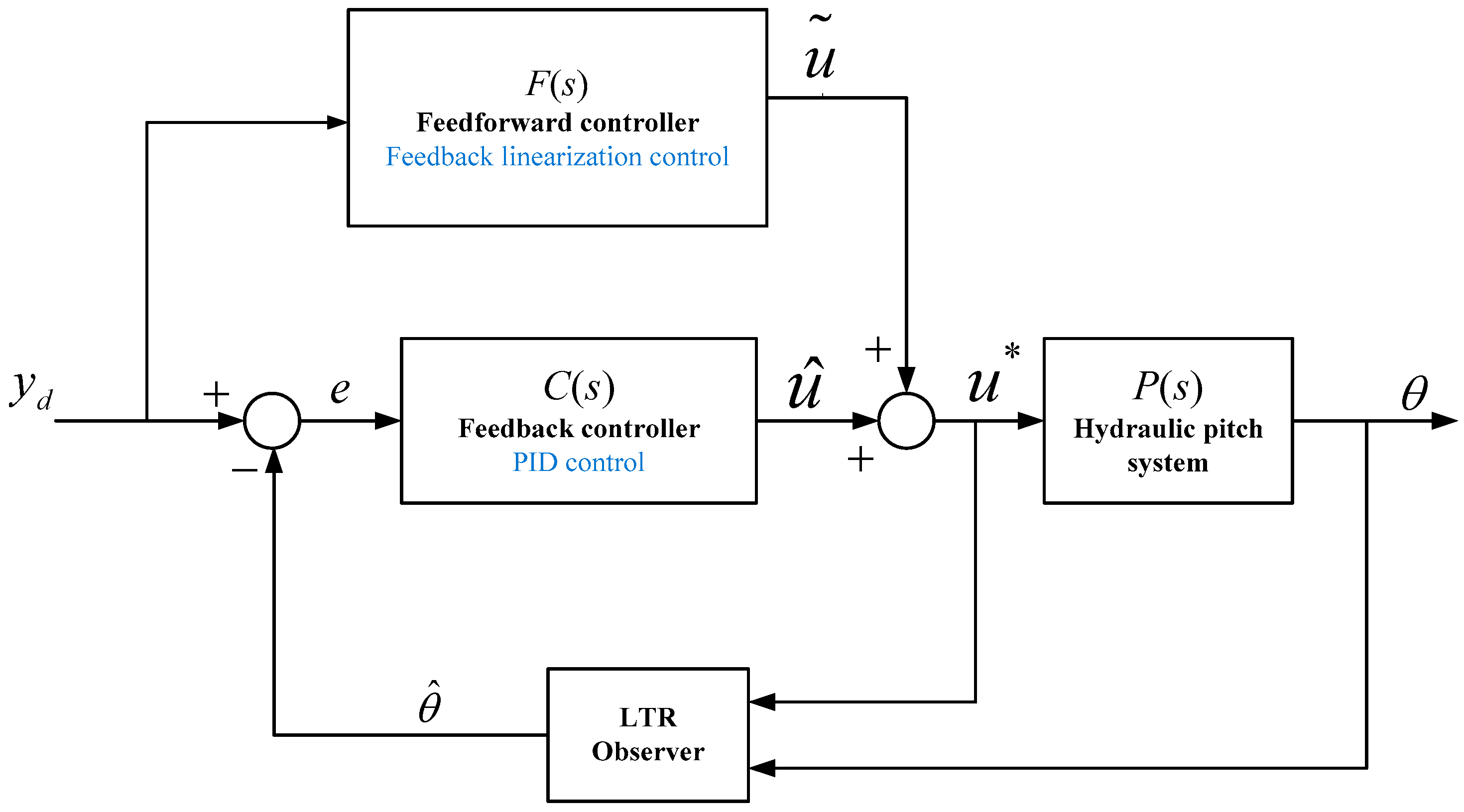
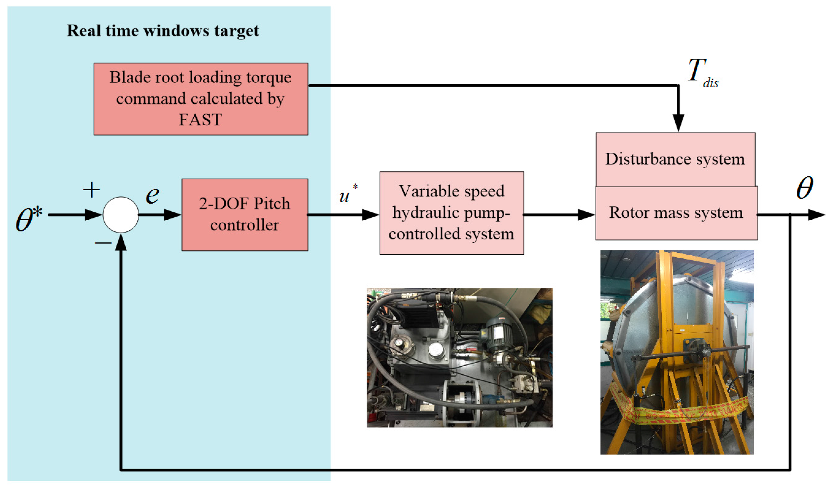
4. Pitch Controller Design

To realize the novel hydraulic pitch control system, the pitch controller has to be designed firstly. A feedback linearization controller is developed in this study for realizing the path control of the pitch angle in the novel hydraulic pitch control system. However, some uncertainties and mismatch between the experiment and mathematic model still exist. To solve this problem, the two degree-of-freedom (2-DOF) standard control with feedback and feedforward controller is developed in this study. Section 4.1 introduces the conception of feedback linearization theory. Then stability analysis and pitch controller design are derived in Section 4.2. Finally, Section 4.3 introduces the model reference control of a 2-DOF standard controller combining with feedback linearization controller to improve the pitch control system robustness in experiments.

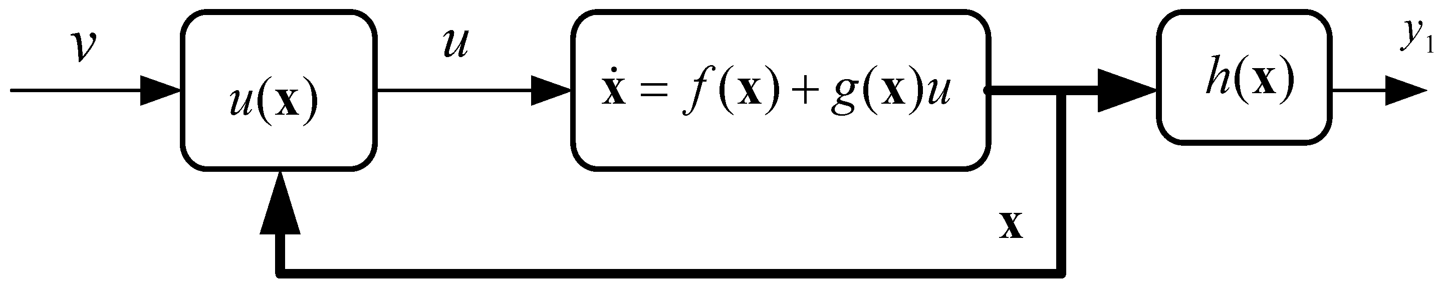
4.1. Theory of Feedback Linearization Control

For a nonlinear system, a state-space nonlinear model can be expressed as Equation (17):
x ˙ = f ( x ) + g ( x ) u y = h ( x ) ,
Assume x as an n-dimensional vector of state variables and can be described with physical situation. The state feedback control law can be derived as Equation (18) if the nonlinear function g ( x ) is non-zero in the operating region. The block diagram is illustrated in Figure 5.
u = ( v f ( x ) ) / g ( x ) ,
Substitute Equation (18) into Equation (17) to linearize the map between the tracking command v and the system output y . Therefore, a linear controller can be designed to satisfy the control objectives. In case that some nonlinear forms may exist in the system and some states have no relation with the system input u , the stability of the zero dynamics is necessary for closed-loop stability.

4.2. Feedback Linearization Control Design for Pitch Controller

4.2.1. Stability Analysis

For the stability analysis, it is reasonable to conjecture that the global stability of the zero dynamics is sufficient for a feedback linearized system to be globally stable. Assume a closed-loop system comprised of a nonlinear system and a well-tuned linearized controller, and then Equation (17) can be rewritten as:
ξ ˙ = A ξ η ˙ = q ( ξ , η ) ,
where ξ is linear state variables, η is nonlinear state variables, and A is a linear matrix.
Since the state variables ξ converge to zero due to the linear characteristics, the closed-loop trajectories can be well controlled. Furthermore, some assumption must be applied to the second equation of Equation (19):
η ˙ = q ( 0 , η )   for   t ,
Equation (20) is known as zero dynamics, which means the nonlinear systems are said to be minimum phase with its zero dynamics. Because the zero dynamics are assumed to be globally stable, the state variables η converge to zero and so does the closed-loop system. However, this argument is correct if the relative degree r   =   1 . It does not hold in general if r     2 . Therefore, the relative degree of pitch control system should be calculated by differentiating the output state of Equation (17), and then combine the state equations of variable rotational speed hydraulic pump-controlled system in Equation (15) so as to alter to Equation (21):
y = x 1 y ˙ = x ˙ 1 = x 2 y ¨ = x ˙ 2 = ( D x 2 C x 1 + A e R cos ( x 1 / 2 ) x 3 ) / J y = x ¨ 2 = { D ( D x 2 C x 1 + A e R sin ϕ 2 x 3 ) C x 2 + A e R L c [ cos ( ϕ 1 + x 1 ) x 2 sin ( ϕ 1 + x 1 ) X ˙ ] x 3 / X 2 } / J + 4 β A e R sin ϕ 2 ( A e X ˙ C e x 3 ) / J V + A e R sin ϕ 2 4 β D e u / J V ,
Compared Equation (17) with Equation (21), both of them are 3rd order state equations so that the internal state is a zero order equation. This means the relative degree of the variable rotational speed hydraulic pump-controlled system is 0 ( r   =   0 ). Thus, the controllability of this system is valid and proved.

4.2.2. Controller Design

Since the stability of the system has been verified, we can determine a third order state equation of external state y in Equation (22) where the output state variable y 1 equals to the state variable x 1 in this study:
y ˙ = [ 0 1 0 0 0 1 0 0 0 ] [ y y ˙ y ¨ ] + [ 0 0 1 ] y y 1 = x 1 ,
Consider this model as a nonlinear state feedback system, and the control objectives can be achieved with a nonlinear static state feedback control law of the form. According to Equation (18), we can simplify the expression of external equation as:
u = ( β ( x ) + v + y ) / α ( x ) ,
where α ( x ) and β ( x ) are nonlinear functions which can be referenced from the forth equation of Equation (21). Thus, the control law linearizes the map between tracking target v and output state variable y 1 .
Define the tracking target v interns of the tracking error factor E and the state feedback gain K r from Equation (23). By setting the desired poles for the linearized system, a proper feedback gain K r is determined. Then we denote the error vector as a matrix of error state which is obtained from the differences between the desired path and the current path. Thus, system can achieve path trajectory control and the desired path y d can approach y 1 if the target v converges to zero. Thus, the tracking target v can be derived as a function of tracking error factor E in Equation (24).
v = K r E ,
After the feedback gain is determined by the outer state of linear system in Equation (22), the designed control input u is able to be calculated. With different control objectives, three desired poles are confirmed by using pole placement to implement an appropriate control performance:
[ p 1 p 2 p 3 ] = [ 50 10 + 5 i 10 5 i ] ,
Therefore, the state feedback gain K r can be obtained.
K r = [ 5050 1101 70 ] ,
Finally, a feedback linearization control input can be achieved in Equation (27):
u = ( β + K r E + y ( r ) ) / α ,

4.3. Feedback Linearization Control Design for Pitch Controller

A high performance requirement of motion system can use the two-degree-of-freedom (2-DOF) controller structure, as shown in Figure 6, where F ( s ) , C ( s ) , and P ( s ) indicate the feedforward controller, the feedback controller, and the model plant respectively. Since the system is considered as a linear time-invariant plant, the objective is to minimize the tracking error function, which can be expressed as [24]:
e / y d = 1 P F / 1 + P C = S ( 1 P F ) ,
where S   =   ( 1   +   PC ) 1 is a sensitivity function. This strategy works well as the feedforward controller F is as close as the inverse of P . In other words, the error function converges to zero as P F 1 . In fact, several factors make feedforward controller F far away from P 1 , such as nonlinearity and unmeasurable parameters. Besides, the feedforward controller is usually designed as a linear time invariant plants. A typical way to design feedforward controller in industry is acceleration feedforward [24], which is always tuned online with a simple gain to correct the uncertainty of overall loop gain. However, instead of the conventional feedforward controller, this study proposes the feedback linearization control in Equation (27) to design the feedforward controller. The designed feedback linearization control input u ( x ) compensates the nonlinear system to serve as a third-order linear dynamic system in Section 4.2, and helps the feedforward control input u ˜ overcome the nonlinearity of the testbed of the novel hydraulic pitch control system. Other mismatches like unknown disturbance and parameter mismatches can be solved by the feedback controller designed by PID control. Thus, this new control input u * , a summation of the feedforward control input u ˜ and the feedback control input u ^ , can not only enhance the tracking performance with the feedforward controller, but also guarantee the robust stability by applying the feedback controller.
Thus, the feed forward controller input u ˜ can be replaced with the calculated input from Equation (27). By summing the feedforward control input u ˜ and feedback input u ^ , a 2 DOF controller input can be achieved as Equation (29):
u * = u ˜ + u ^ u ˜ = u = ( β + K r E + y ( r ) ) / α ,
Finally, for implementing the controller to the real test rig, some specific problem should be solved. The rotary encoder used in our system has only 18,000 pulses per cycle. Although resolution can be improved through quadrature, it is still not appropriate to get the angular velocity by directly taking numerical derivative of the measured angle, especially when the motion is slow under high sampling frequency [32]. Thus, the system can be estimated well in this test rig to reduce the influence of high frequency noisy.

5. Experiments of Novel Hydraulic Pitch Control System

This section contains two different parts to verify the novel hydraulic pitch control system and the controller design. The 2-DOF controller combining with feedback linearization controller is implemented to improve the robustness of the system. The overall system works under “Real-time Windows Target” in MATLAB/SIMULINK. Figure 7 illustrates the overall system of hardware-in-the-loop for the wind turbine pitch control system. Finally, the experimental results show an excellent response in tracking performance and disturbance rejection.

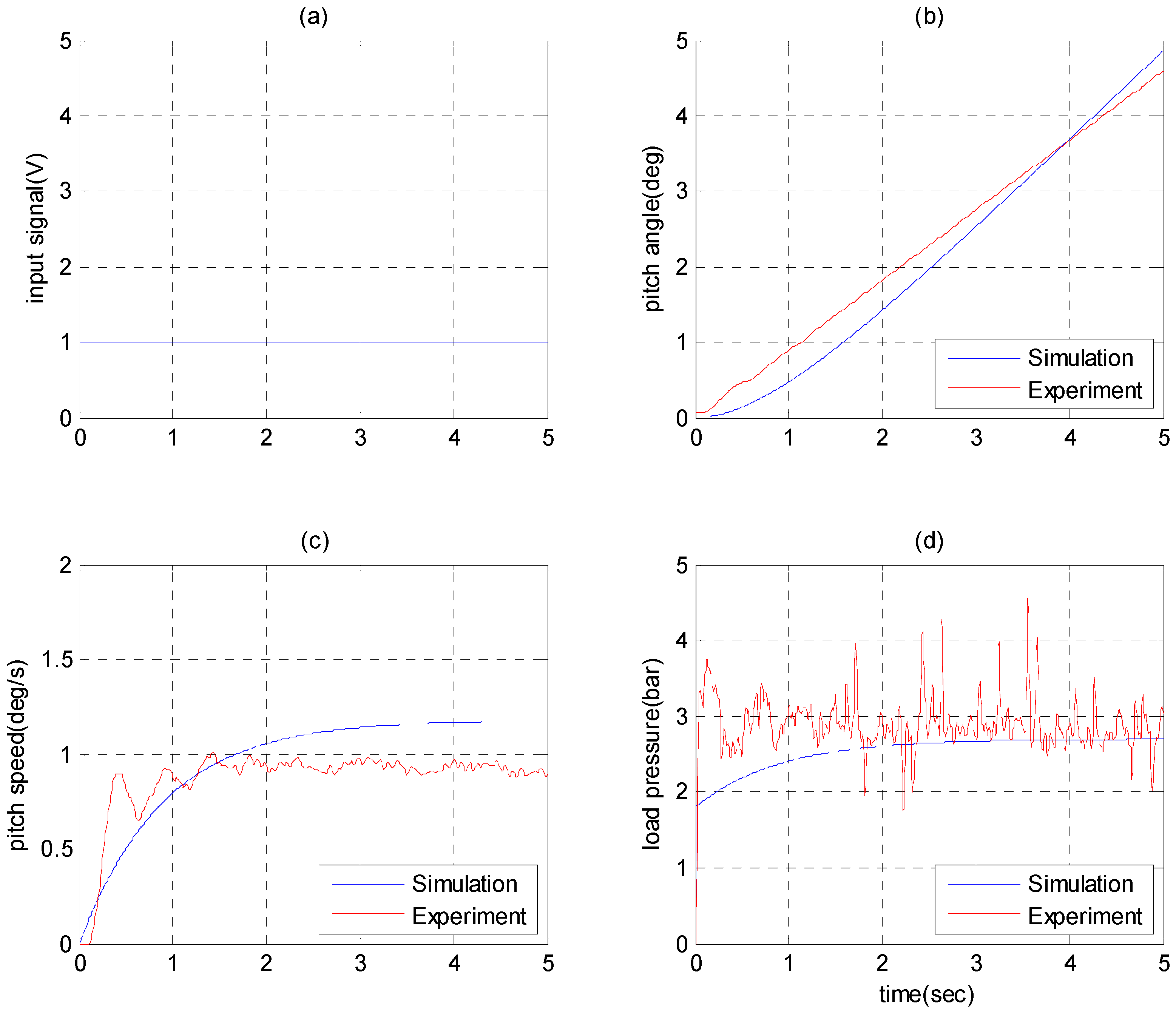
5.1. Model Validation

It is important to verify the correspondence between the derived model and the practical experimental system, which affects the tracking control performance of the pitch controller in the experiment of the test rig. The load pressure and the pitch angle are compared with a step input. Figure 8 shows the comparison result with input signal u   =   1 ; Figure 8a represents the time response of input signal, while Figure 8b–d expresses the consistence with experiment and model simulation result in dynamic response of system state, respectively. Although some difference of load pressure between model simulation and experimental measurement exist due to the nonlinearities that cannot be considered in the model, the model is sufficient for the controller design of the 2-DOF controller for pitch control.

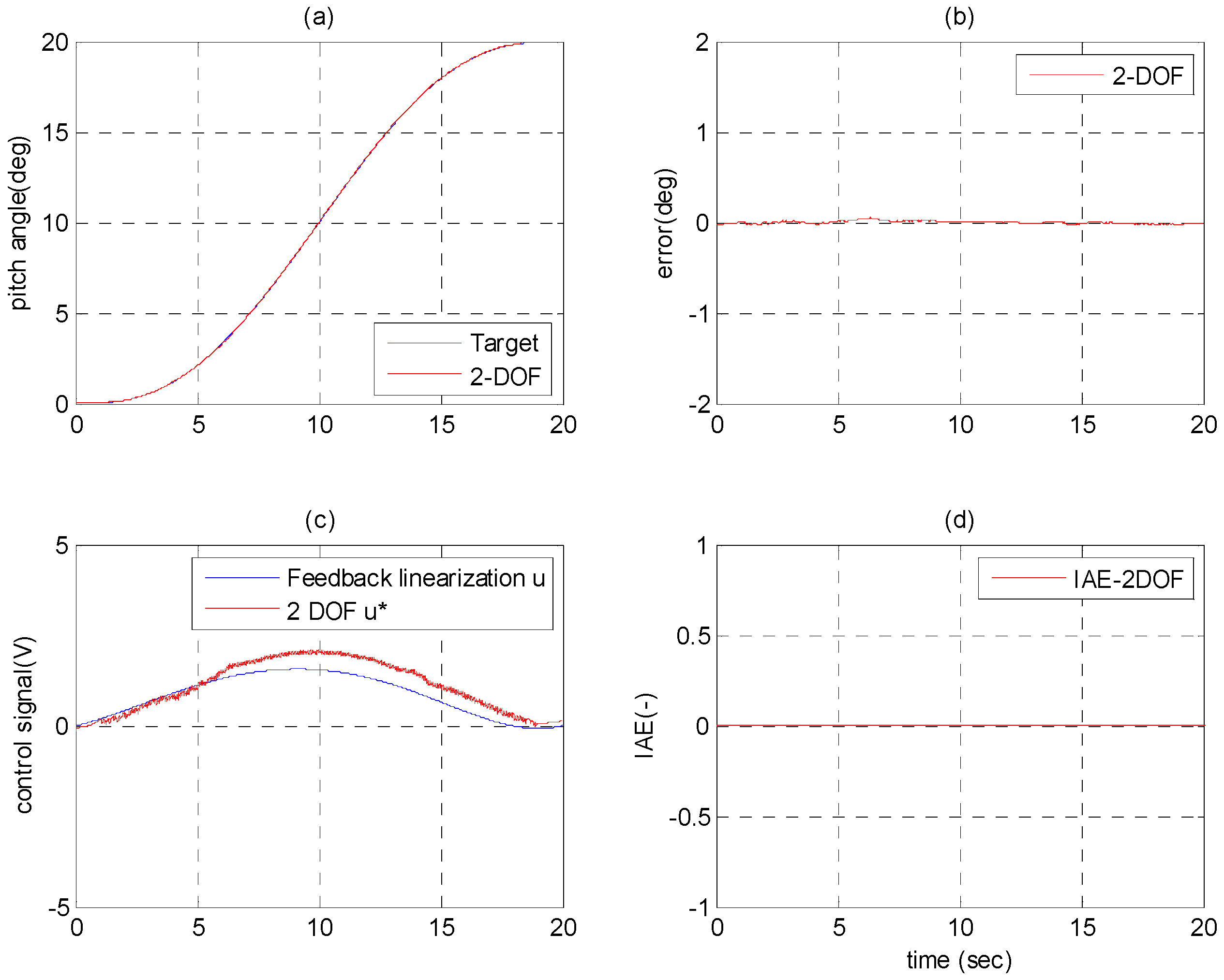
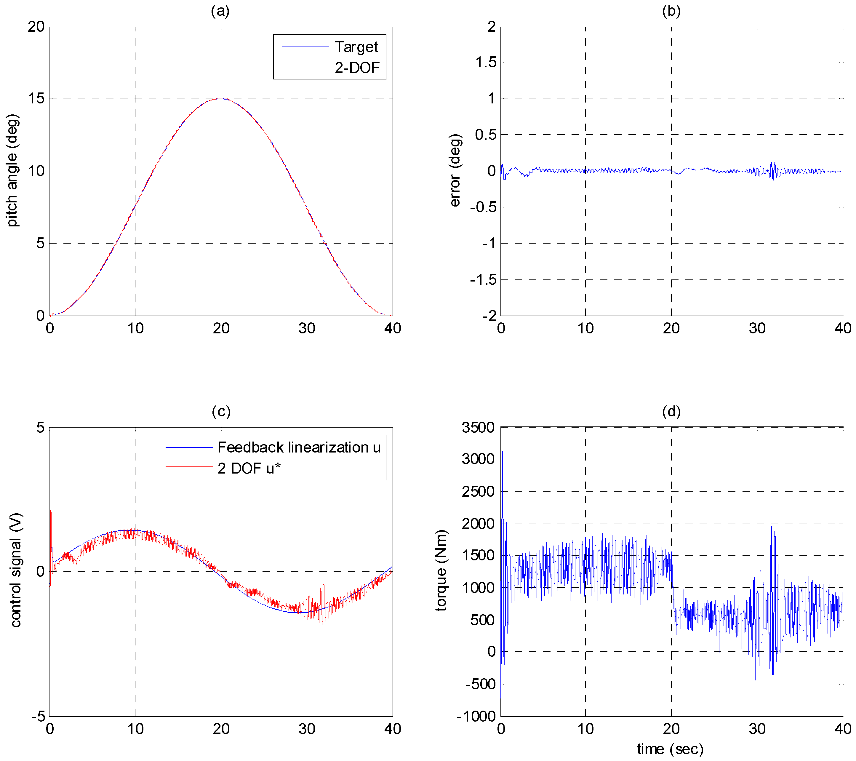
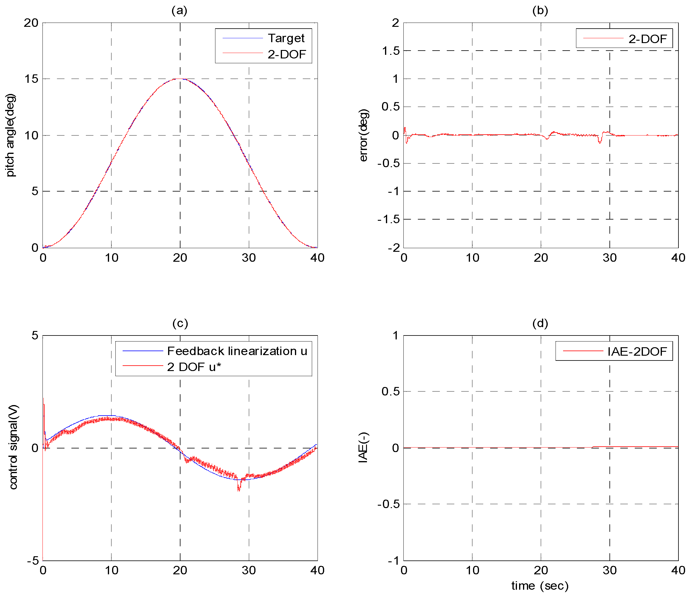
5.2. Experiments of Path-Positioning Control and Path Control

In order to realize the path tracking control and positioning control simultaneously, a jerk-free path profile of 5th order polynomial is given. Figure 9 shows the experimental result of the path-positioning control with pitch angle stroke of 20° in 20 s, including the pitch angle response in Figure 9a, the pitch angle control error in Figure 9b, and the comparison of 2-DOF control signals and feedforward control signals in Figure 9c. The pitch angle tracking error during the motion can achieve within ± 0.1°. Furthermore, Figure 9c schematically depicts that the inverse feedforward control signals u are much closer to the input signals u * such that the effect of the feedback linearization control applied to the 2-DOF controller can be proved. Thus, the performance of the novel pitch control system driven by the variable rotational speed hydraulic pump-controlled system can be confirmed.
Besides, the control results of the 2-DOF motion controller in Figure 9 also show excellent performance in path-positioning control. Moreover, for further comparing the performance of path-positioning control, a performance criterion, Integral of Absolute Error (IAE) is used.
IAE = | e | d t ,
As shown in Figure 9d, the 2-DOF motion controller implements a good pitch control performance. The value of IAE of the 2-DOF motion controller can be kept within 0. Thus, the 2–DOF motion controller can not only increase the robustness of the pitch control but also improve the tracking performance significantly.
The bi-directional motion of the novel pitch control system can be performed by implementing with the path control of a sinusoidal path with amplitude of 15° and period of 40 s, as shown in Figure 10. The experimental results schematically depicts that the path tracking control of the pitch angle can be achieved well, and the control error can be kept within ± 0.5°. The feedforward controller fits even more perfectly in sinusoidal path than 5th order trajectory. The IAE value of the 2-DOF controller still keeps the IAE less than 0.5. Therefore, the validity of the path-positioning control with the 2-DOF controller can be proved, and the excellent response with the compensation of 2-DOF motion controller can be confirmed.

5.3. Disturbance Rejection of Pitch Control System

With the purpose of investigating the robustness of the developed novel pitch control system controlled by the 2-DOF controller, the disturbance loading torque is inserted through setting the pressure proportional valves in the disturbance system. Figure 11 shows the experimental results of the path-positioning control of the pitch angle with stroke of 15° in 20 s under the loading torque calculated by the disturbance system model derived in Equation (17) where the practical measurement results of wind speed of a 2MW wind turbine in Taiwan are given. The disturbance loading torque is inserted during the path-positioning control. The control error of pitch angle can be kept within about 0.5° in Figure 11b. Thus, the robust control performance of the proposed pitch control system by the 2-DOF controller is verified. In Figure 11c, the feedback controller compensates the loads from disturbance to guarantee the tracking performance.
In sinusoidal path control, a high frequency disturbance was loaded to the rotor-mass system to simulate a high fluctuating wind input. As illustrated in Figure 12, the tracking performance was still guaranteed by feedforward controller and the feedback controller rejects the high frequency loads.

6. Conclusions

This paper proposed a novel hydraulic pitch control system of wind turbines driven by a variable rotational speed pump-controlled hydraulic system controlled by the 2-DOF controller. In order to implement practical experiments of the pitch control, the full-scale test rig of the hydraulic pitch control system of a 2 MW wind turbine’s blade driven by the variable rotational speed pump-controlled hydraulic servo system is set up. Besides, to accomplish the pitch control in the proposed novel pitch control system, the 2-DOF controller combining feedback controller with feedforward controller has been developed to design the pitch controller. A more progress and improvement regards to the previous work, this study developed a 2-DOF motion controller with feedback linearization which not only simplified the controller but also guarantee the tracking performance when comparing with previous study. Therefore, the proposed novel pitch control system has been realized and verified by the path tracking control and the path-positioning control of the pitch angle by implementing the practical experiments in the full-scale test rig under different path profiles, including a 5th order polynomial and a sinusoidal profile. Furthermore, the 2-DOF controller can improve the robustness and the stability due to the excellent response by loading an unmeasurable disturbance generated by the simulated disturbance profile by the wind turbine simulation software FAST. This new designed disturbance profile makes the experiment test bed more convincible and increase the possibility of realizing the hydraulic pump controlled pitch system to a real wind turbine. Finally, the experiment of the path control of pitch angle under random wind speed and load torque has been implemented with excellent control performance.

Acknowledgments

The research was sponsored in part by the Ministry of Science and Technology, Taiwan under the grant MOST 104-3113-E-002-016-CC2 and MOST 105-3113-E-002-015-CC2.

Author Contributions

Mao-Hsiung Chiang conceived and designed the experiments; Ching-Sung Wang performed the experiments and designed the controller. Mao-Hsiung Chiang and Ching-Sung Wang wrote the paper.

Conflicts of Interest

The authors declare no conflict of interest.

Abbreviations

The following abbreviations are used in this manuscript:
FASTFatigue, Aerodynamics, Structures and Turbulence
CFDComputational Fluid Dynamics
DOFDegree Of Freedom
IAEIntegral of Absolute Error
AeroDynAeroDynamic
ACAlternating Current
MATLABMATrix LABoratory

References

  1. Wilmshurst, S.M.B. Control strategies for wind turbines. Wind Eng. 1988, 12, 236–249. [Google Scholar]
  2. Freeman, J.B.; Balas, M.J. Direct model reference adaptive control of a variable speed horizontal axis wind turbines. Wind Eng. 1988, 22, 25–33. [Google Scholar]
  3. Petru, T.; Thiringer, T. Modeling of wind turbines for power system studies. IEEE Trans. Power Syst. 2002, 17, 1132–1139. [Google Scholar] [CrossRef]
  4. Huang, C.; Li, F.; Jin, Z. Maximum power point tracking strategy for large-scale wind generation systems considering wind turbine dynamics. IEEE Trans. Ind. Electron. 2015, 62, 2530–2539. [Google Scholar] [CrossRef]
  5. Kim, K.H.; Van, T.L.; Lee, D.C.; Song, S.H.; Kim, E.H. Maximum Output Power Tracking Control in Variable-Speed Wind Turbine Systems Considering Rotor Inertial Power. IEEE Trans. Ind. Electron. 2013, 60, 3207–3217. [Google Scholar] [CrossRef]
  6. Chen, J.; Chen, J.; Gong, C. New Overall Power Control Strategy for Variable-Speed Fixed-Pitch Wind Turbines within the Whole Wind Velocity Range. IEEE Trans. Ind. Electron. 2013, 60, 2652–2660. [Google Scholar] [CrossRef]
  7. Jones, R.; Smith, G.A. High quality mains power from variable speed wind turbines. Wind Eng. 1994, 18, 45–49. [Google Scholar]
  8. Idan, M.; Lior, D. Continuously variable speed wind turbine: Transmission concept and robust control. Wind Eng. 2000, 24, 151–167. [Google Scholar] [CrossRef]
  9. Song, Y.D.; Dhinakaran, B.; Bao, X.Y. Variable speed control of wind turbines using nonlinear and adaptive algorithms. J. Wind Eng. Ind. Aerodyn. 2000, 85, 293–308. [Google Scholar] [CrossRef]
  10. Boukhezar, B.; Siguerdidjane, H. Nonlinear Control of Variable Speed Wind Turbines without wind speed measurement. In Proceedings of the 44th IEEE Conference on Decision and Control 2005, Seville, Spain, 12–15 December 2005; pp. 3456–3461.
  11. Camblong, H.; Tapia, G.; Rodriguez, M. Robust digital control of a wind turbine for rated-speed and variable-power operation regime. IEE Proc. Control Theory Appl. 2006, 153, 81–91. [Google Scholar] [CrossRef]
  12. Liserre, M.; Cardenas, R.; Molinas, M.; Rodriguez, J. Overview of Multi-MW Wind Turbines and Wind Parks. IEEE Trans. Ind. Electron. 2011, 58, 1081–1095. [Google Scholar] [CrossRef]
  13. Muljadi, E.; Butterfield, C.P. Pitch-controlled variable-speed wind turbine generation. IEEE Trans. Ind. Appl. 2001, 37, 240–246. [Google Scholar] [CrossRef]
  14. Duong, M.Q.; Grimaccia, F.; Leva, S.; Mussetta, M.; Ogliari, E. Pitch angle control using hybrid controller for all operating regions of SCIG wind turbine system. Renew. Energy 2014, 70, 197–203. [Google Scholar] [CrossRef]
  15. Xiao, S.; Geng, H.; Yang, G. Non-linear pitch control of wind turbines for tower load reduction. IET Renew. Power Gener. 2014, 8, 786–794. [Google Scholar] [CrossRef]
  16. Wang, J.; Tse, N.; Gao, Z. Synthesis on PI-based pitch controller of large wind turbines generator. Energy Convers. Manag. 2011, 52, 1288–1294. [Google Scholar] [CrossRef]
  17. Gao, R.; Gao, Z. Pitch control for wind turbine systems using optimization, estimation and compensation. Renew. Energy 2016, 91, 501–515. [Google Scholar] [CrossRef]
  18. Zamani, M.H.; Fathi, S.H.; Riahy, G.H.; Abedi, M.; Abdolghani, N. Improving Transient Stability of Grid-Connected Squirrel-Cage Induction Generators by Plugging Mode Operation. IEEE Trans. Energy Conver. 2012, 27, 707–714. [Google Scholar] [CrossRef]
  19. Helduser, S. Electric-hydrostatic drive—An innovative energy-saving power and motion control system. Proc. Inst. Mech. Eng. 1999, 213, 427–439. [Google Scholar] [CrossRef]
  20. Habibi, S.; Goldenberg, A. Design of a new high performance electro-hydraulic actuator. In Proceedings of the 1999 IEEE/ASME International Conference on Advanced Mechatronics, Atlanta, GA, USA, 19–23 September 1999; pp. 227–232.
  21. Chiang, M.H. A novel pitch control system for a wind turbine driven by a variable-speed pump-controlled hydraulic servo system. Mechatronics 2011, 21, 753–761. [Google Scholar] [CrossRef]
  22. Chiang, M.H.; Wang, C.S.; Chen, C.S. Intelligent Pitch Control for a 2MW Wind Turbine. Int. J. Fuzzy Syst. 2012, 14, 89–96. [Google Scholar]
  23. Krener, A.J. On the Equivalence of Control Systems and the Linearization of Nonlinear Systems. SIAM J. Control 1973, 11, 670–676. [Google Scholar] [CrossRef]
  24. Brockett, R.W. Feedback Invariants for Nonlinear Systems. In Proceedings of the 7th IFAC Congress, Helsinki, Finland, 12–16 June 1978; pp. 1115–1120.
  25. Jakubczyk, B.; Respondek, W. On Linearization of Control Systems. Bull. Acad. Polonaise Sci. Ser. Sci. Math. 1980, 28, 517–522. [Google Scholar]
  26. Kwon, J.H.; Kim, T.H.; Jang, J.S.; Lee, I.Y. Feedback Linearization Control of a Hydraulic Servo System. In Proceedings of the 2006 SICE-ICASE International Joint Conference, Busan, Korea, 18–21 October 2006.
  27. Nguyen, Q.H.; Ha, Q.P.; Rye, D.C.; Durrant-Whyte, H.F. Feedback linearization control for electrohydraulic systems of a robotic excavator. In Proceedings of the Australian Conference for Robotics and Automation, Auckland, New Zealand, 6–8 December 2006.
  28. Boerlage, M.; Steinbucht, M.; Lambrechtst, P.; Wal, M. Model-based feedforward for motion systems. In Proceedings of the 2003 IEEE Conference on Control Applications, Istanbul, Turkey, 23–25 June 2003; pp. 1158–1163.
  29. Devasia, S. Robust inversion-based feedforward controllers for output tracking under plant uncertainty. In Proceedings of the 2000 American Control Conference, Chicago, IL, USA, 28–30 June 2000; pp. 497–502.
  30. Torfs, D.E.; Vuerinckx, R.; Swevers, J.; Schoukens, J. Comparison of two feedforward design methods aiming at accurate trajectory tracking of the end point of a flexible robot arm. IEEE Trans. Control Syst. Technol. 1998, 6, 2–14. [Google Scholar] [CrossRef]
  31. Jonkman, J.M.; Buhl, M.L., Jr. FAST User’s Guide; National Renewable Energy Laboratory (NREL): Golden, CO, USA, 2005.
  32. Skogestad, S.; Postlethwaite, I. Multivariable Feedback Control: Analysis and Design; Wiley: New York, NY, USA, 1996. [Google Scholar]
Figure 1. Novel hydraulic pitch control system: (a) pitch control by two hydraulic cylinders; (b) variable-speed hydraulic pump-controlled system.
Energies 09 00791 g001
Figure 2. Test rig of novel variable pitch control system of wind turbine driven by hydraulic pump-controlled dual-cylinder system.
Energies 09 00791 g002
Figure 3. Photograph of test rig of novel hydraulic pitch control system: (a) rotor mass system; (b) variable pump controlled system.
Energies 09 00791 g003
Figure 4. Geometric relation of mechanism for driving system.
Energies 09 00791 g004
Figure 5. Block diagram of feedback linearization theory.
Energies 09 00791 g005
Figure 6. Block diagram of standard two degree-of-freedom (2-DOF) controller in motion system.
Energies 09 00791 g006
Figure 7. Hardware in the loop for wind turbine pitch control system.
Energies 09 00791 g007
Figure 8. Model verification with step input 1 V: (a) Input signal; (b) Comparison of pitch angle; (c) Comparison of pitch speed; (d) Comparison of load pressure.
Energies 09 00791 g008
Figure 9. Experimental result of 5th order path-positioning control of pitch angle with 2-DOF controller, stroke 20° in 20 s with no load: (a) Pitch angle response; (b) Pitch angle error; (c) Comparison of control signals; (d) Integral of absolute error.
Energies 09 00791 g009
Figure 10. Experimental results of sinusoid path control of pitch angle with, amplitude 15°, period 40 s with no load: (a) Pitch angle response; (b) Pitch angle error; (c) Comparison of control signals; (d) Integral of absolute error.
Energies 09 00791 g010
Figure 11. Experimental results of path-positioning control of pitch angle with stroke 15° in 20 s and load torque: (a) Pitch angle response; (b) Pitch angle error; (c) Comparison of control signals; (d) Disturbance load.
Energies 09 00791 g011
Figure 12. Experimental results sinusoid path control of pitch angle with amplitude of 15°, period 40 s and load torque: (a) pitch angle response; (b) pitch angle control error; (c) comparison of input signals; (d) disturbance load.
Energies 09 00791 g012
Table 1. Specifications of the test rig.
ComponentSpecification
AC servo motorRated rotational speed: 2000 rpm
Servo motor driverMax. output power: 7.5 kW
Hydraulic pumpSwash plate axial piston pump
Fixed displacement: 12 mL/rev
Hydraulic servo cylinderSingle rod double acting cylinder
Max. stroke: 810 mm
Piston diameter: 50 mm
Rod diameter: 25 mm
Disturbance cylinder systemSingle rod double acting cylinder
Max. stroke: 400 mm
Piston diameter: 50 mm
Rod diameter: 25 mm
Rotor mass systemWeight: 2050 kgw
Moment of inertia: 1238 kg·m2
Table 2. The disturbance torque under different pitch angles and wind speed.
Pitch Angle (°)0510
Wind Speed (m/s)
111428 (Nm)867 (Nm)141 (Nm)
121600 (Nm)1020 (Nm)280 (Nm)
131765 (Nm)1182 (Nm)445 (Nm)
141929 (Nm)1335 (Nm)574 (Nm)
152114 (Nm)1500 (Nm)730 (Nm)
162266 (Nm)1672 (Nm)900 (Nm)
172420 (Nm)1824 (Nm)1035 (Nm)
182554 (Nm)2000 (Nm)1206 (Nm)
192707 (Nm)2138 (Nm)1355 (Nm)
202830 (Nm)2307 (Nm)1547 (Nm)

