Article

Optimum Geometric Transformation and Bipartite Graph-Based Approach to Sweat Pore Matching for Biometric Identification

1
Department of Image, Chung-Ang University, 84 Heukseok-ro, Dongjak-gu, Seoul 06974, Korea
2
Department of Electronics and Computer Engineering, Hanyang University, 222 Wangsimni-ro, Seongdong-gu, Seoul 04763, Korea
*
Author to whom correspondence should be addressed.
Symmetry 2018, 10(5), 175; https://doi.org/10.3390/sym10050175
Submission received: 19 April 2018 / Revised: 11 May 2018 / Accepted: 16 May 2018 / Published: 20 May 2018

Abstract

:
Sweat pores on the human fingertip have meaningful patterns that enable individual identification. Although conventional automatic fingerprint identification systems (AFIS) have mainly employed the minutiae features to match fingerprints, there has been minimal research that uses sweat pores to match fingerprints. Recently, high-resolution optical sensors and pore-based fingerprint systems have become available, which motivates research on pore analysis. However, most existing pore-based AFIS methods use the minutia-ridge information and image pixel distribution, which limit their applications. In this context, this paper presents a stable pore matching algorithm which effectively removes both the minutia-ridge and fingerprint-device dependencies. Experimental results show that the proposed pore matching algorithm is more accurate for general fingerprint images and robust under noisy conditions compared with existing methods. The proposed method can be used to improve the performance of AFIS combined with the conventional minutiae-based methods. Since sweat pores can also be observed using various systems, removing of the fingerprint-device dependency will make the pore-based AFIS useful for wide applications including forensic science, which matches the latent fingerprint to the fingerprint image in databases.

1. Introduction

Since the human fingerprint is unique and not easy to imitate, fingerprint recognition has played an essential role in various applications, such as personal authentication, security investigation, and border control over the last few decades. In automatic fingerprint identification systems (AFIS), image features for the fingerprint recognition are hierarchically categorized into three levels: Level 1 (pattern), Level 2 (points), and Level 3 (shape) [1,2]. Level 1 refers to macro details including the overall ridge flow and orientation. Because Level 1 features have little information, they are commonly helpful for the sketchy morphological categorization of fingerprints (e.g., arch, left loop, right loop, and double loop). Level 2 features cover Galton details and minutiae points (terminations and bifurcations of the friction ridge). Most studies in AFIS have focused on utilizing Level 2 features so far because they have enough patterns to recognize the human individuality [3]. Level 3 encompasses many fine details on the fingerprint that include ridge edge, ridge width, scars, and sweat pores. They carry an extensive amount of information. In fact, it is known that human latent fingerprint investigators often examine Level 3 features for the manual fingerprint recognition. Nevertheless, there have been relatively few researches utilizing Level 3 features including pore because it is hard to extract meaningful information from the fingerprint images whose spatial resolution is far less than 800 dpi [4]. Since high-resolution optical sensors (≥1000 dpi) have been recently developed for the fingerprint recognition [4,5], Level 3 features become an attractive key to meet the increasing level of recent security demand for AFIS.
Among Level 3 features, sweat pores on fingertip are highly discriminative, permanent, immutable, and abundant [6,7,8]. For instance, Ashbaugh argued that 20 to 40 sweat pores are sufficient for human identification [6]. Zhao et al. also observed that 50 to 100 sweat pores are detectable in a small area of 8 mm × 6 mm on 1000 dpi high-quality fingerprint images on average [7]. Furthermore, in addition to the high-resolution optical sensors, as various pore-based fingerprint imaging systems [9,10] have become available for the pore analysis, sweat pores will turn into a more helpful feature for AFIS. Therefore, sweat pore-based fingerprint matching method attracts increasing interests.
As the earliest study for pore-based AFIS in 1994, Stosz and Alyea presented a fingerprint identification system which combined ridge and pore information [11]. They firstly segmented the fingerprint into many sub-image regions based on the extracted fingerprint features, estimated the initial alignment using image correlation between the manually selected segments, and then used the exhaustive search to find the best alignment in the parameter space. Based on the earlier work in [11], Roddy and Stosz statistically analyzed the effectiveness of pores in addition to minutiae features [8]. Kryszczuk et al. proposed a fingerprint fragmentary matching method by introducing the geometric distance criterion [12].
More recently, Jain et al. devised a hierarchical fingerprint recognition system using all three levels of features [5]. In this method, the minutiae features on two comparing fingerprints are aligned and paired using the string-matching algorithm based on Level 1 and Level 2 features. Next, the sweat pores adjacent to the paired minutiae are matched by using the iterative closed point algorithm which finds the minimum distance between two clouds of points. These methods demonstrated that the sweat pore is discriminative and useful for AFIS. However, because these methods treat sweat pores based on the result estimated by minutia-ridge information, the pore matching accuracy is sensitive to the minutia-ridge matching accuracy. In other words, these methods cannot provide satisfying matching results when the minutia-ridge data is reduced or unavailable.
Zhao et al. discovered that reducing this minutia-ridge dependency makes the pore matching result more powerful, and they presented a direct pore matching method [13]. In Zhao’s method, the circular image region centered on each extracted pore is directly cropped for the descriptor after some preprocessing steps. During this process, they referred to the ridge orientation to make their descriptor rotation-invariant. After calculating the correlation between the feature vectors from two different fingerprints, correspondences are determined and then refined by the random sample consensus (RANSAC) algorithm. Liu et al. improved the direct pore matching method by introducing the sparse representation [14]. By reducing the minutia-ridge dependency, these methods showed that the recognition accuracy could be improved. However, they still in part use the minutia-ridge data (ridge orientation). In addition, since these methods exploit the sub-image patch as the feature vector for each pore, their methods depend on the pixel value distribution, which results in their methods to be fingerprint-device dependent. This fingerprint-device dependency could diminish the utility of pore-based AFIS.
Most recently, Cui et al. presented a pore matching method using polar histogram [15]. Since this method uses only the relative position of neighboring pores to create a descriptor for each pore, it could effectively reduce the dependency on image sources. However, Cui’s pore matching method adopts a simple thresholding technique to mate pairs and allows the one-to-many pore matching states, which results in a sensitive result to various types of noise, such as pore extraction error and malfunctioning of pores (not secreting sweat).
In this paper, we present a novel pore-matching method to remove both minutia-ridge and fingerprint-device dependencies for enhancing the performance and utilization of the pore-based AFIS. To this end, the proposed sweat pore matching method uses the optimum geometric transformation and bipartite graph-based approach. The proposed method consists of six steps: (i) generation of local descriptors using the relative locations of adjacent pores; (ii) construction of similarities between the sweat pores; (iii) estimation of the geometric transformation between two pore images using the RANSAC algorithm; (iv) refinement of the transformation using Levenberg-Marquardt algorithm (LMA); (v) search for the stable matching state between two pore sets through the bipartite graph approach and (vi) the final calculation of the matching score.
This paper is organized as follows: Section 2 briefly summarizes the technical background, Section 3 presents the proposed sweat pore matching method. After Section 4 summarizes experimental result, and Section 5 concludes the paper.

2. Technical Background

Sweat pores can technically be observed using two types of systems: (i) live-scan fingerprint sensors and (ii) pore-based fingerprint imaging systems. This section briefly introduces the technical background about these two types of pore images and their characteristics.

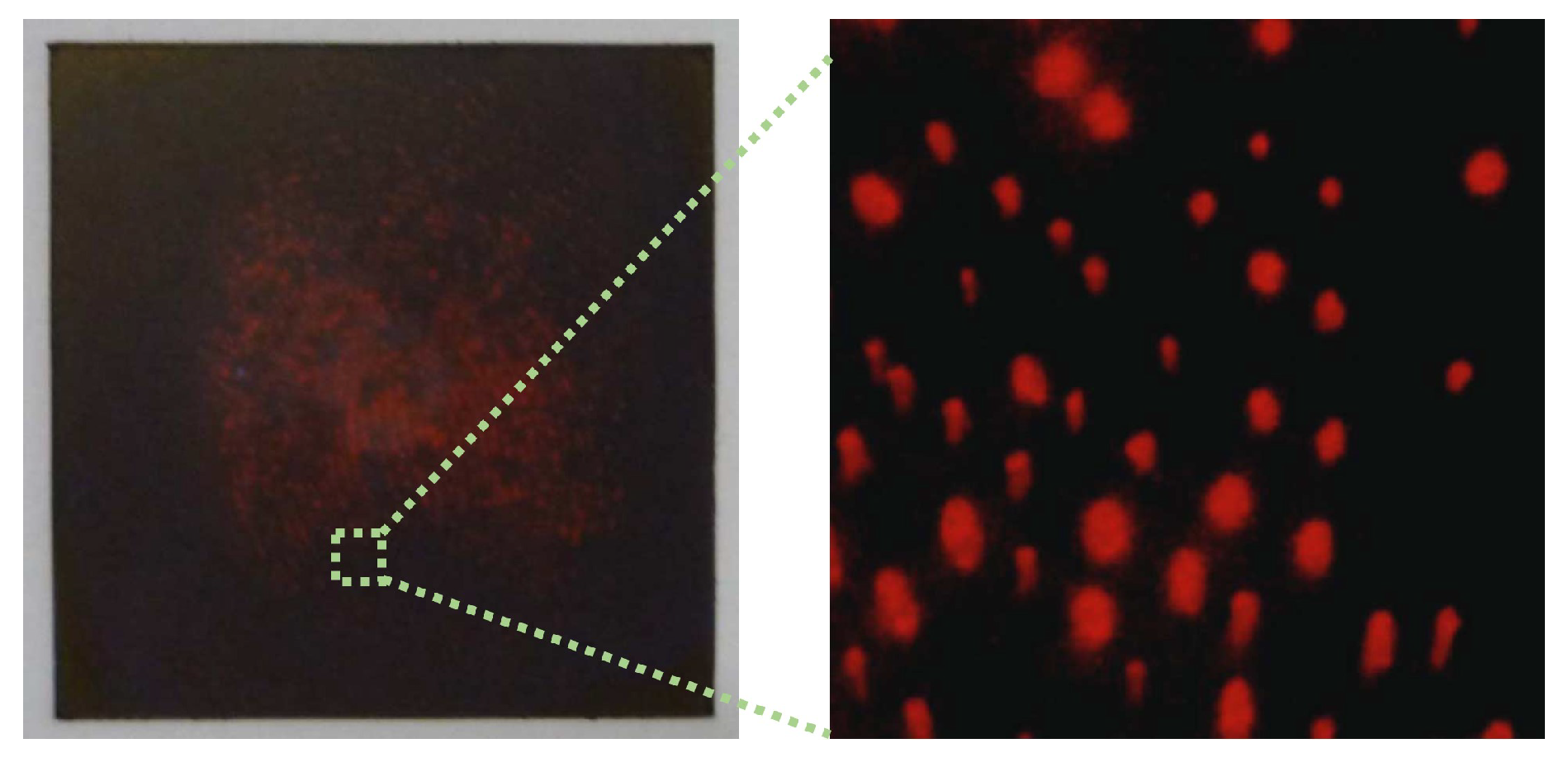
2.1. Live-Scan Fingerprint Image

Figure 1 shows a high-resolution fingerprint image taken by a live-scan digital imaging sensor with 1200 dpi resolution [16]. Sweat pores are uniformly distributed upon the ridges of the fingerprints and take circular shapes. Sweat pores on live-scan fingerprint can be divided into open and closed pores, as marked in Figure 1.
Several pore extraction methods have recently been proposed using live-scan fingerprint images [5,12,17,18,19]. Kryszczuk et al. proposed a morphological skeleton-based pore extraction method [12]. Ray et al. proposed a pore extraction method using an isotropic 2D Gaussian model [17], and Jain et al. used the Mexican hat wavelet transform to extract sweat pores on fingerprints [5]. Zhao et al. observed that all sweat pores are not exactly isotropic, and proposed a dynamic anisotropic model-based pore extraction method [18]. In order to reduce the computational complexity of the 2D models, Cui et al. presented 1D Gaussian model-based pore extraction method [19]. In summary, on live-scan fingerprint images, these pore extraction methods first extract the friction ridge and then detect sweat pores using its visual characteristics (i.e., the circle-like pattern). However, the extracted locations of sweat pores are inaccurate when the fingerprint image has low-resolution under 1000 dpi or severe degradation.

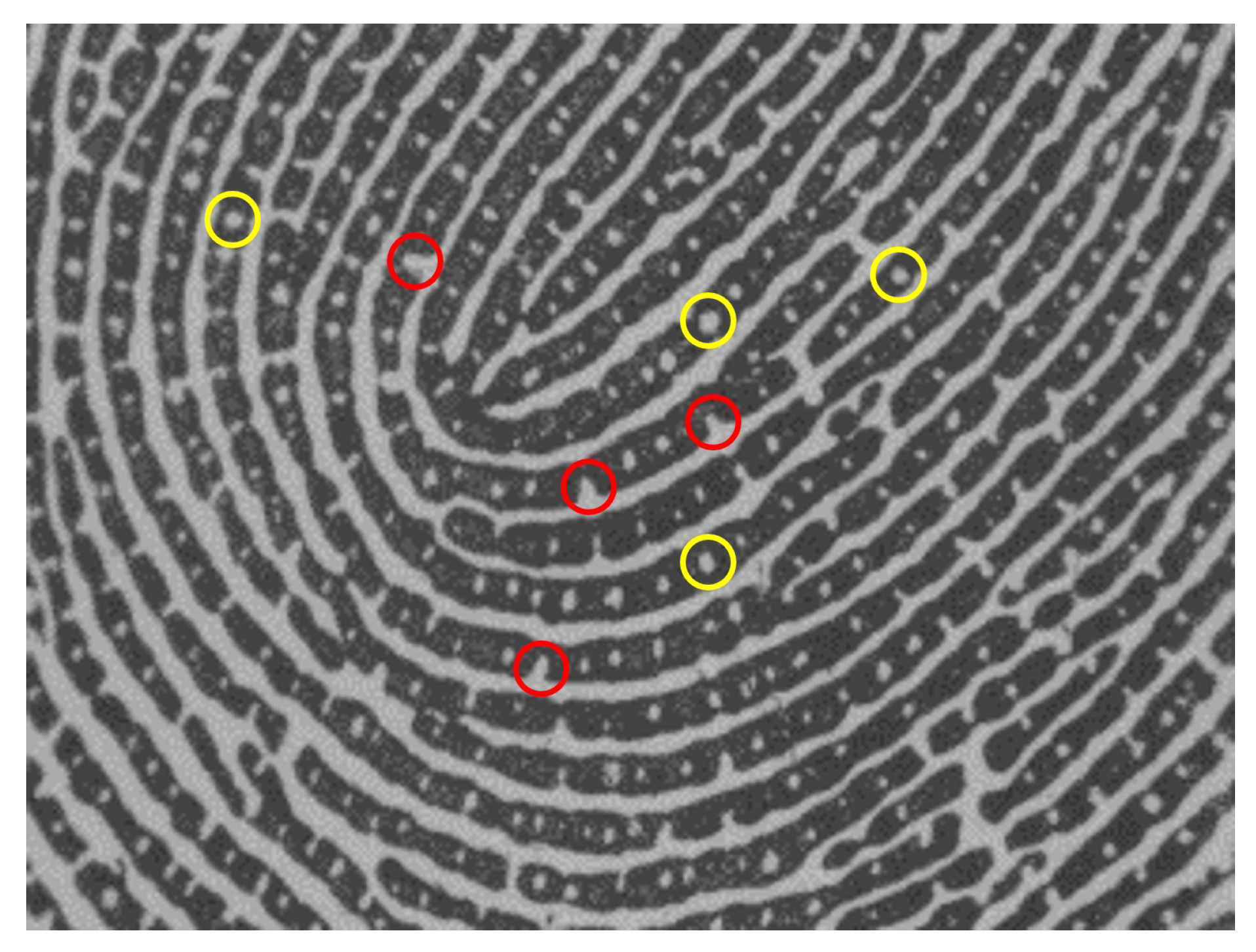
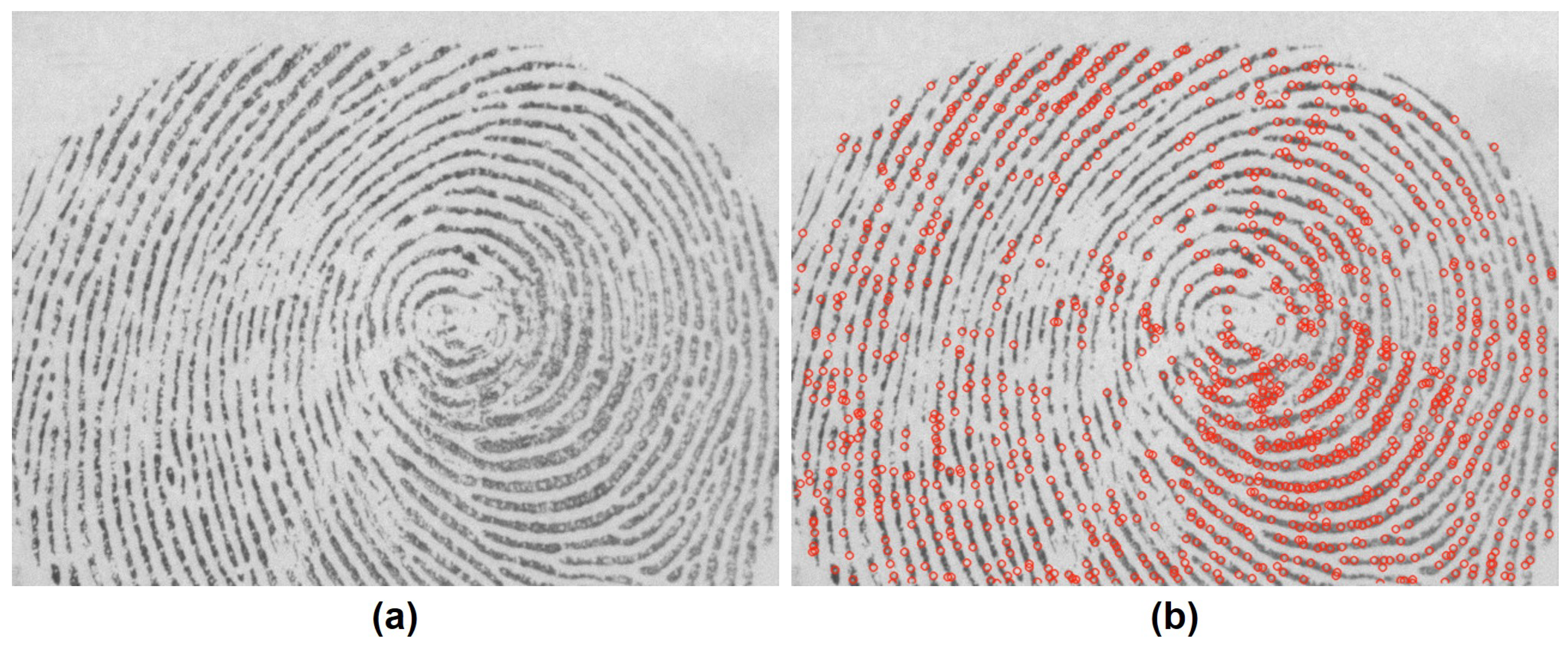
2.2. Pore-Based Fingerprint Image

Pore-based fingerprint imaging systems take advantage of the fact that the pores commonly secrete the sweat, which involves many ingredients. For instance, a pore-based hydrochromic sensor system employs polydiacetylene that changes its color when meeting water [9]. Similarly, Elsner presented a latent pore imaging approach by analyzing the ingredients of human perspiration [10]. Figure 2 shows that sweat pores in the pore-based fingerprint imaging system can be readily and accurately detectable using a simple image processing method, such as the image thresholding and centroid techniques [9,10].
In the sense of physiology, sweat pores can be classified into three groups: active, inactive, and inconsistent pores. Active pores always secrete the sweat normally, whereas inactive pores do not. On the other hand, inconsistent pores act like the active pores but occasionally do not excrete by malfunction. For this reason, the missing sweat pore error frequently arises from the pore-based fingerprint images.

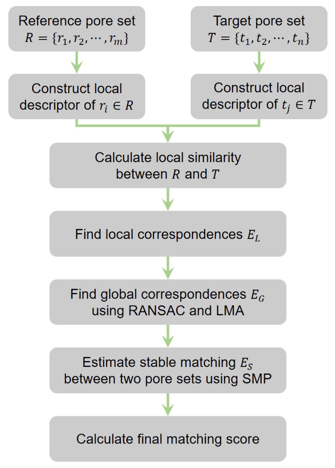
3. Geometric Transformation and Bipartite Graph-Based Approach to Sweat Pore Matching

The procedure of the proposed pore matching algorithm is outlined in Figure 3. We first build the local descriptor for each pore. By comparing all local descriptors generated from the pair of pore sets, we find several locally corresponding pore-pairs. Based on the local correspondence, we find a geometric transformation between two pore sets using RANSAC. Next, the LMA is used to refine the estimated transformation. As the bipartite graph point of view with considering both local and global correspondences, we find a stable matching between two pore sets. The final matching score is then calculated using the size of the estimated edge set.

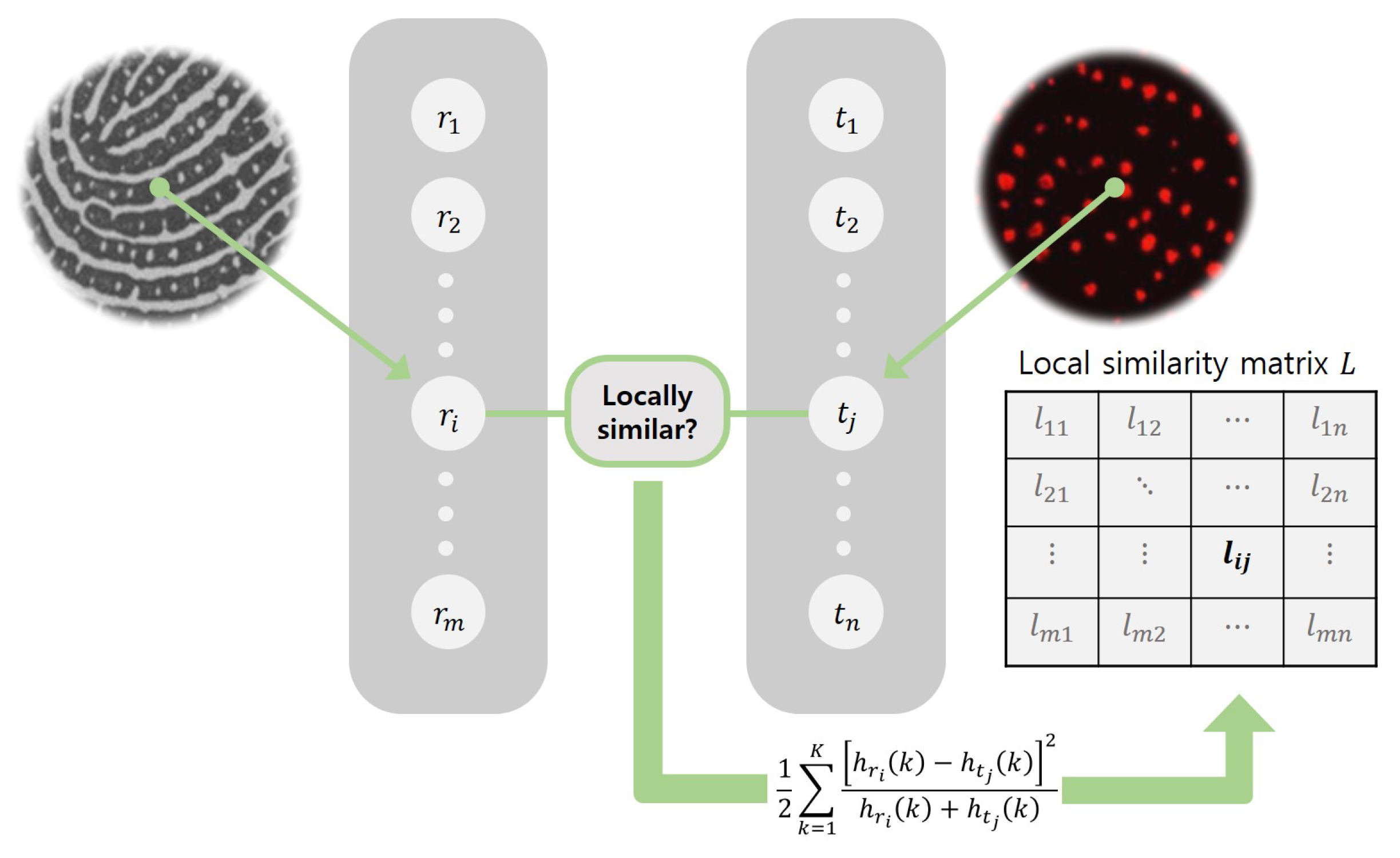
3.1. Problem Statement

We begin with some notations and definitions to describe the proposed pore matching algorithm. From two fingerprint images, two sets of the pore locations are acquired. One pore set is denoted as the reference pore set R, and the other as the target pore set T. The goal of pore matching is to decide whether these pore sets are given from the same person or not.
Let R = { r 1 , r 2 , , r m } and T = { t 1 , t 2 , , t n } respectively denote the reference and target pore sets, where m and n are the total numbers of extracted pores in each set. Then, the detected locations of pores r i R and t j T can be represented as r i = ( x r i , y r i ) and t j = ( x t j , y t j ) , respectively. If two pore images are captured from the same finger, it is assumed that:
  • Local similarity: If two pores r i and t j are mated each other in the final matching state, they would have the similar distribution patterns of neighboring pores.
  • Global similarity: There is a certain geometric relationship between two pore sets, consistently in the entire picture.
Thus, after calculating the local and global similarity scores of all possible pore-pairs, we construct local and global correspondences between two pore sets. The more correspondences are found, the more likely two pore sets are considered to be identical. However, it is difficult to get the perfect matching between R and T, since there exist many degradation factors, such as noise, partial damage, different types of sensors, inaccurately extracted pores, and malfunctioned pores. In order to find a stable one-to-one matching result in this work, the pore matching problem is considered to be a bipartite graph matching problem with two vertex sets R and T. Then, the problem now becomes the estimation of a stable edge set E S from the bipartite graph G = { R , T , E } .

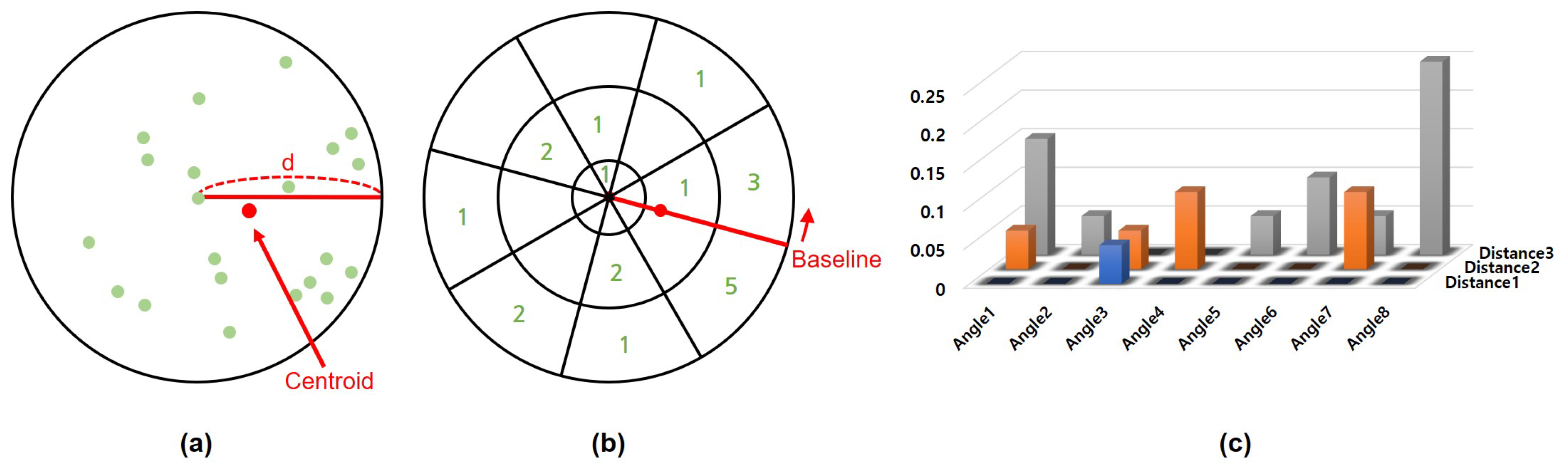
3.2. Local Correspondence

In order to examine how much a pore-pair ( r i , t j ) has similar local distributions of adjacent pores, the polar histogram, which is also used in Cui’s method [15], is generalized in this paper as the local descriptor. The polar histogram measures both distance and angular distributions of the adjacent pores. An example of constructing the polar histogram is illustrated in Figure 4.
For each pore r i R and t j T , we can define their neighboring pores N ( r i ) and N ( t j ) as
N ( r i ) = { r k | d i s t ( r i , r k ) d R ,   r k R ,   k i } ,
N ( t j ) = { t k | d i s t ( t j , t k ) d T ,   t k T ,   k j } ,
where r i and t j represent the circle centers, and d R and d T are radii of the corresponding circles. d i s t ( · , · ) is the Euclidean distance between two pores. If two pore images are captured by the different resolution sensors, d R would not be equal to d T . They are calculated as
d R = 1 m 2 r p R r q R 1 2 d i s t ( r p , r q ) ,
d T = 1 n 2 t p T r q T 1 2 d i s t ( t p , t q ) .
As a result, the radius of the circle becomes independent on the image resolution. We also use the centroid locations c ( r i ) and c ( t j ) of the neighboring pores as the baseline of angular binning for each polar histogram, respectively, as
c ( r i ) = 1 | N ( r i ) | r k N ( r i ) r k ,
c ( t j ) = 1 | N ( t j ) | t k N ( t j ) t k ,
where | N ( · ) | represents the number of neighboring pores. The local descriptor calculated in this way is invariant to rotation and translation of fingerprints. Note that only the relative position of neighboring pores is needed to generate the polar histogram. Thus, the proposed pore matching method is independent of other information in fingerprints.
After generating the local feature descriptors of pores, a local similarity score matrix L is constructed. Let h r i and h t j denote the generated polar histograms of r i R and t j T , respectively. As shown in Figure 5, the i-th row and j-th column entry l i j of the local similarity matrix L is calculated using the Chi-squared distance as
l i j = 1 χ 2 ( h r i , h t j ) = 1 1 2 k { h r i ( k ) h t j ( k ) } 2 h r i ( k ) + h t j ( k ) + γ ,
where γ is a small regularization constant to prevent the denominator from being zero. Based on this local similarity matrix L, the local correspondence E L can be established. If l i j has the maximum value along both row i and column j, then ( r i , t j ) is considered to have local correspondence, i.e., ( r i , t j ) E L .

3.3. Global Correspondence

If two pore images are taken from the same finger, there must exist a certain geometric transformation that registers two images. In other words, when any correspondence ( r i , t j ) belongs to E L , which is a true match, it can be associated in the homogeneous form as
x t j y t j 1 = M x r i y r i 1 ,
where M is the geometric transformation matrix. The global correspondence step estimates this geometric transformation and then finds the global correspondences E G with reference to E L . One out of planar transformation models including rigid, similarity, affine, and projective can be considered for M. When two fingerprints are captured from different devices that are installed with different geometric contact surfaces, they could have a different level of aspect ratio, projective distortion, and lens distortion. So we use the projective transformation in this work. The projective transformation gives a proper compromise between the degree-of-freedom for fingerprint deformation and computational costs. The projective transformation is shown in Table 1. With respect to the projective transformation, the residual error e ( r i , t j ) of any correspondence ( r i , t j ) can be derived from Equation (8) using the algebraic distance as
e ( r i , t j ) = 1 m 20 x r i + m 21 y r i + 1 m 00 x r i + m 01 y r i + m 02 m 10 x r i + m 11 y r i + m 12 x t j y t j .
One easy way to find the transformation M is just to apply the direct linear transformation (DLT) and find the least squares (LS) solution of Equation (8) using all the correspondences belonging to E L . However, there exist some outliers together with correctly matching pairs. In order to effectively remove these outliers in the estimate process of the initial transformation matrix M 0 , the RANSAC algorithm is used [20]. The RANSAC algorithm starts by sampling a subset of k correspondences at random. Using only the sampled k correspondences, the tentative transformation M t is then computed as a solution of Equation (8) using DLT and LS. Thus, based on the current M t , each correspondence in E L can be separated into a consensus set E t and the other set E L E t according to e ( r i , t j ) 2 ϵ . The threshold value ϵ is usually set to one to four pixels depending on the applications. In this work, ϵ is calculated as
ϵ = 0.04 × 1 n 2 t p T t q T 1 2 d i s t ( t p , t q ) .
After separating all correspondences in E L , the tentative transformation M t and its consensus set E t with the largest number of consensuses are respectively updated as E 0 and M 0 . This process iteratively refines the solution until the number of iterations reaches the predefined maximum number of iterations N m or the sufficient number of iterations N s . In this approach, N m is fixed to 1000. N s is updated at each iteration to guarantee that the process sufficiently repeats to find the true inlier set until convergence as follows. Since each of the k correspondences is selected independently from E L , the probability p that the selected correspondence is a true inlier is, at least, assumed to be
p = | E 0 | | E L | ,
where | E 0 | and | E L | are the numbers of pore correspondences in each set. If the sampled k correspondences are all true inliers at each iteration, it is assumed that the transformation is successfully estimated, and the probability is equal to p k in that case. Thus, ( 1 p k ) is the probability that at least one correspondence is included in the outlier set, and fails to estimate the valid transformation. After repeating the process N s times, the probability that fails to estimate the true transformation becomes equal to
1 P s = ( 1 p k ) N s ,
where P s is the probability of success after N s times, which can be calculated as
N s = log ( 1 P s ) log ( 1 p k ) .
Consequently, M 0 for the maximal number of edges in E L is found using the RANSAC algorithm.
At this moment, M 0 is estimated using only the local correspondences E L . If any of the two pore images is partly damaged or contaminated, the local distributions of adjacent pores for a few pores could be drastically changed. Therefore, it is necessary to refine M 0 while considering more pore-pairs than E L . In order to solve this problem, we use the LMA that is commonly known as the iterative damped least-squares method [21,22]. More specifically, the LMA starts at M 0 , and its parameter vector m is repeatedly updated as m + δ , where δ is computed at each iteration as
δ = J T ( m ) J ( m ) + λ d i a g ( J T ( m ) J ( m ) ) 1 J T ( m ) e ( m ) ,
where J ( m ) and J T ( m ) are the Jacobian and its transpose, respectively. e ( m ) is the residual error. The Jacobian matrix and the parameter vector of the transformation are shown in Table 1. As described in (14), the LMA is a combination of the gradient descent and the Gauss-Newton methods. As a result, the optimal transformation M is estimated, and the global similarity matrix G is then calculated as
g i j = 1 e ( r i , t j ) 2 ϵ ,
where g i j is the i-th row and j-th column entry of G. Thus, the global correspondences between R and T are easily obtained as follows. If any pair ( r i , t j ) has the larger global similarity than 0, then the pair is regarded to be a global correspondence. In other words, if g i j > 0 , then ( r i , t j ) E G . By using this LMA step, we can see that the pore matching accuracy is improved by 13.78 % . Experimental results of the estimated global correspondences are shown in Figure 6.

3.4. Stable Pore Matching

Now, there are given two correspondence sets ( E L and E G ) to help decide whether a particular pair of pores are from the same finger or not. However, each of them may not be individually perfect due to the various types of noise in pore images. By treating the pore matching problem as a bipartite graph matching approach, the goal of this stage is to find the stable matching (either edge set or correspondences) E S and to calculate the matching score between R and T.
In the bipartite graph structure, the problem of finding a stable matching between two sets has been called the stable marriage problem or stable matching problem (SMP) [23,24,25]. In SMP, a matching is called unstable if both of the following conditions are satisfied: (i) there exists a pore r i that more prefers the pore t j than the currently mated pore t q and (ii) the pore t j also more prefers r i than its mated pore r p . In some literature [23,24,25], it has been guaranteed that the solution of SMP and its variants can always be obtainable and stable. In order to obtain a stable one-to-one pore matching result, we adopt SMP in this paper.
In each iteration, each unmated reference pore in R proposes to the most preferred target pore that it has not yet proposed and has the local or global correspondence. Then, the proposed target pore (i) accepts the proposal if it has no partner, or (ii) selects one with higher preference if already engaged. the local and global correspondence condition is added to speed up the SMP algorithm. The whole procedure is described in Algorithm 1.
Finally, the matching score between R and T is computed as
f ( R , T ) = ( r i , t j ) E S p i j × | E S | min ( | R | , | T | ) ,
where p i j is the i-th row and j-th column entry of the preference matrix P and min ( · , · ) is the smaller one of two input values. Let’s assume that there are given a query pore image and a lot of fingerprints in the database. Then, we can find the identity of the query pore image as
q u e r y ( R ) = argmax T D a t a b a s e f ( R , T ) .
Algorithm 1: Stable pore matching
Symmetry 10 00175 i001

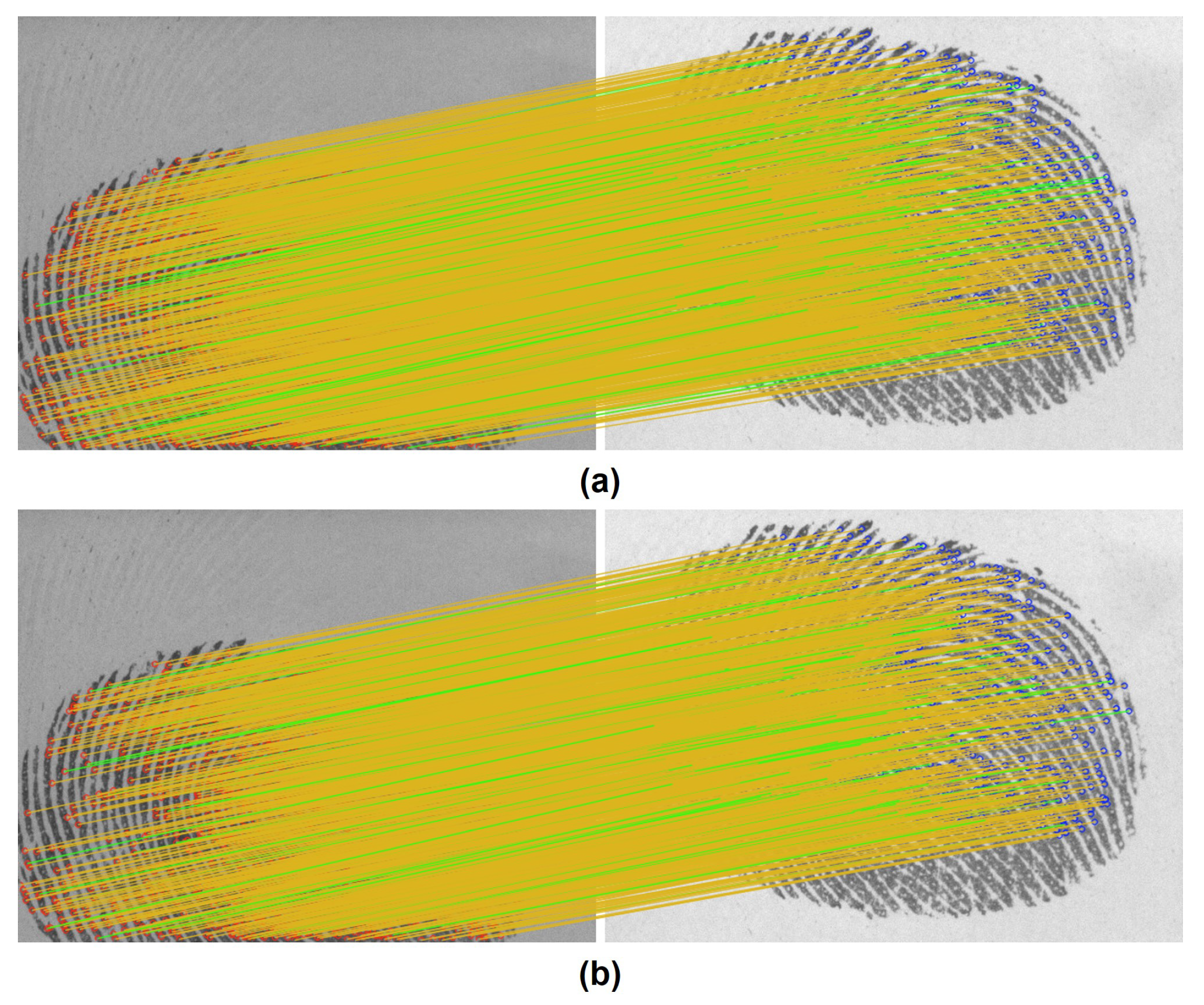
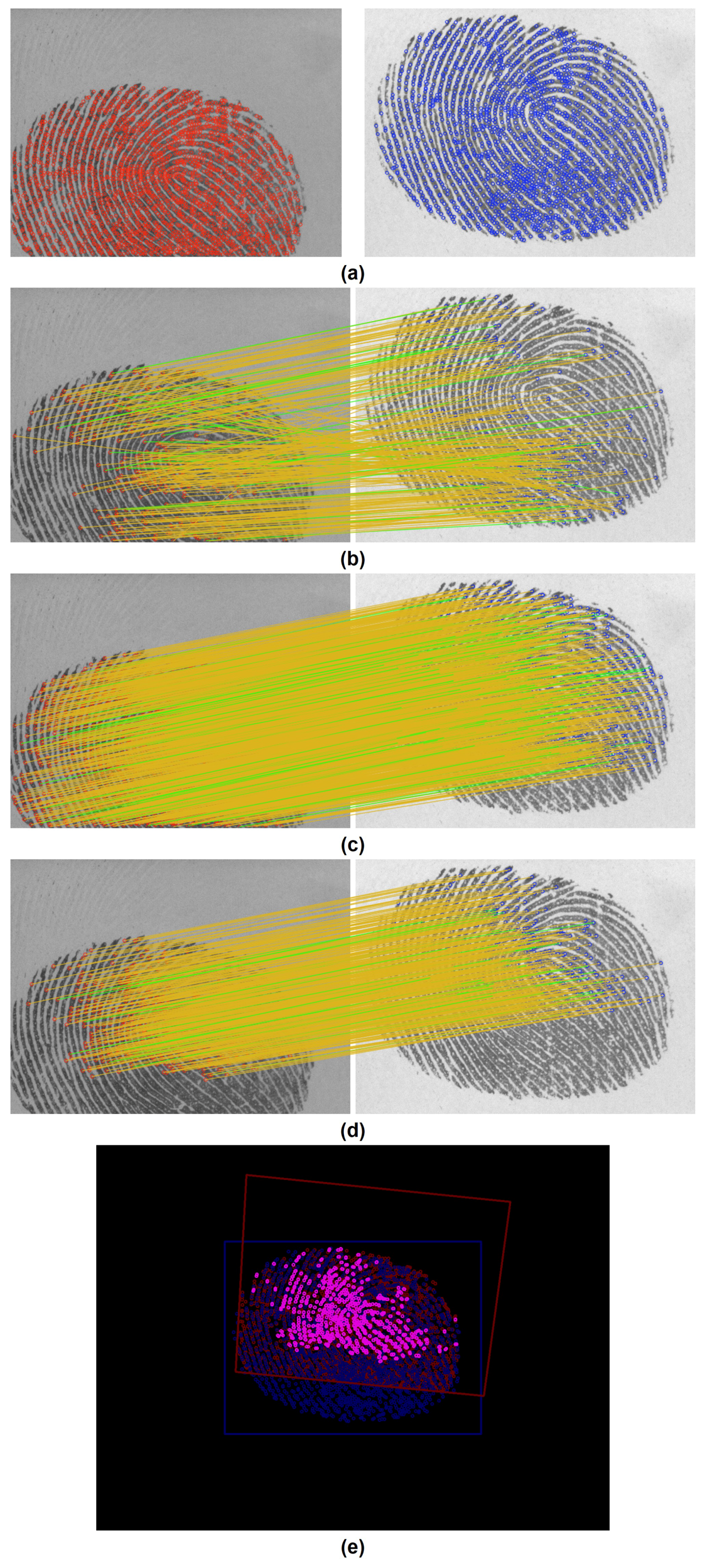
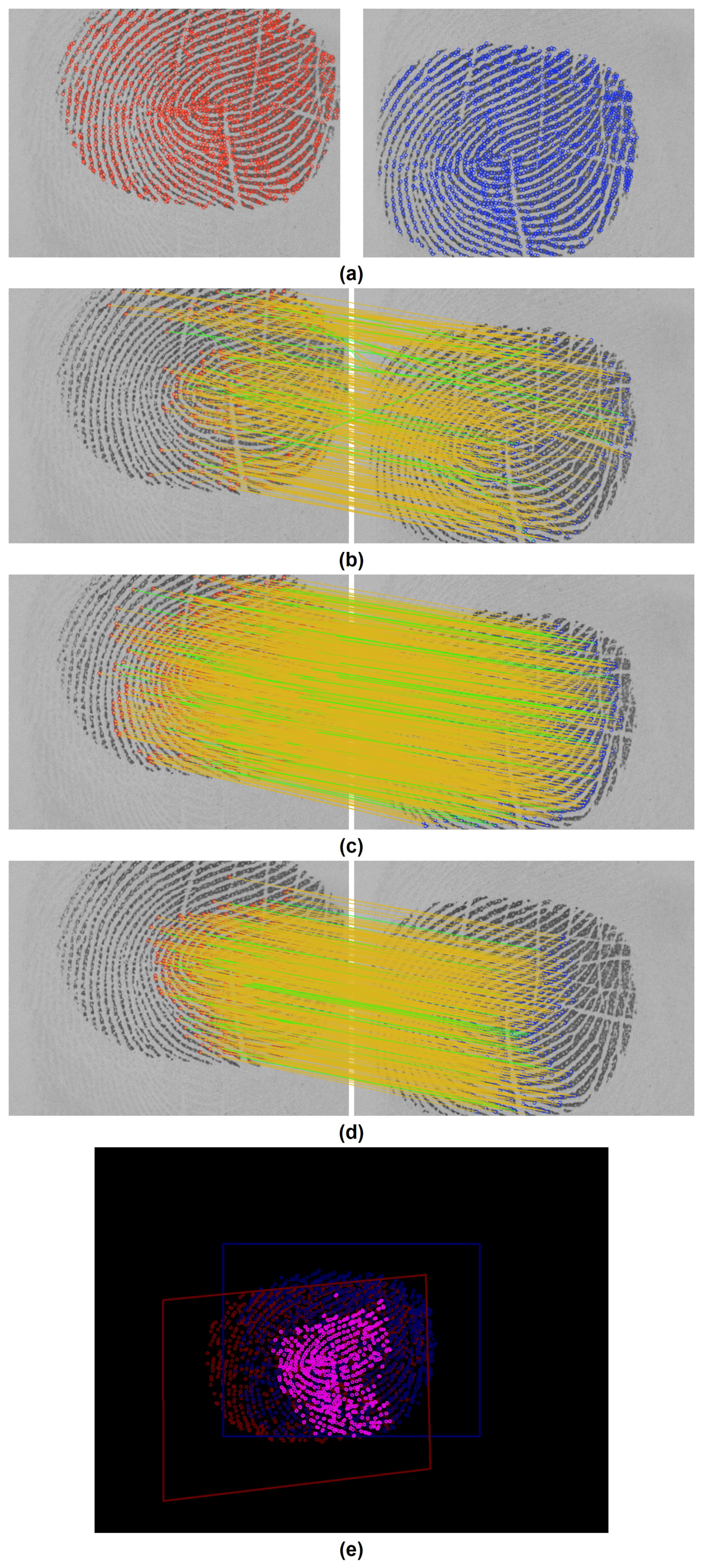
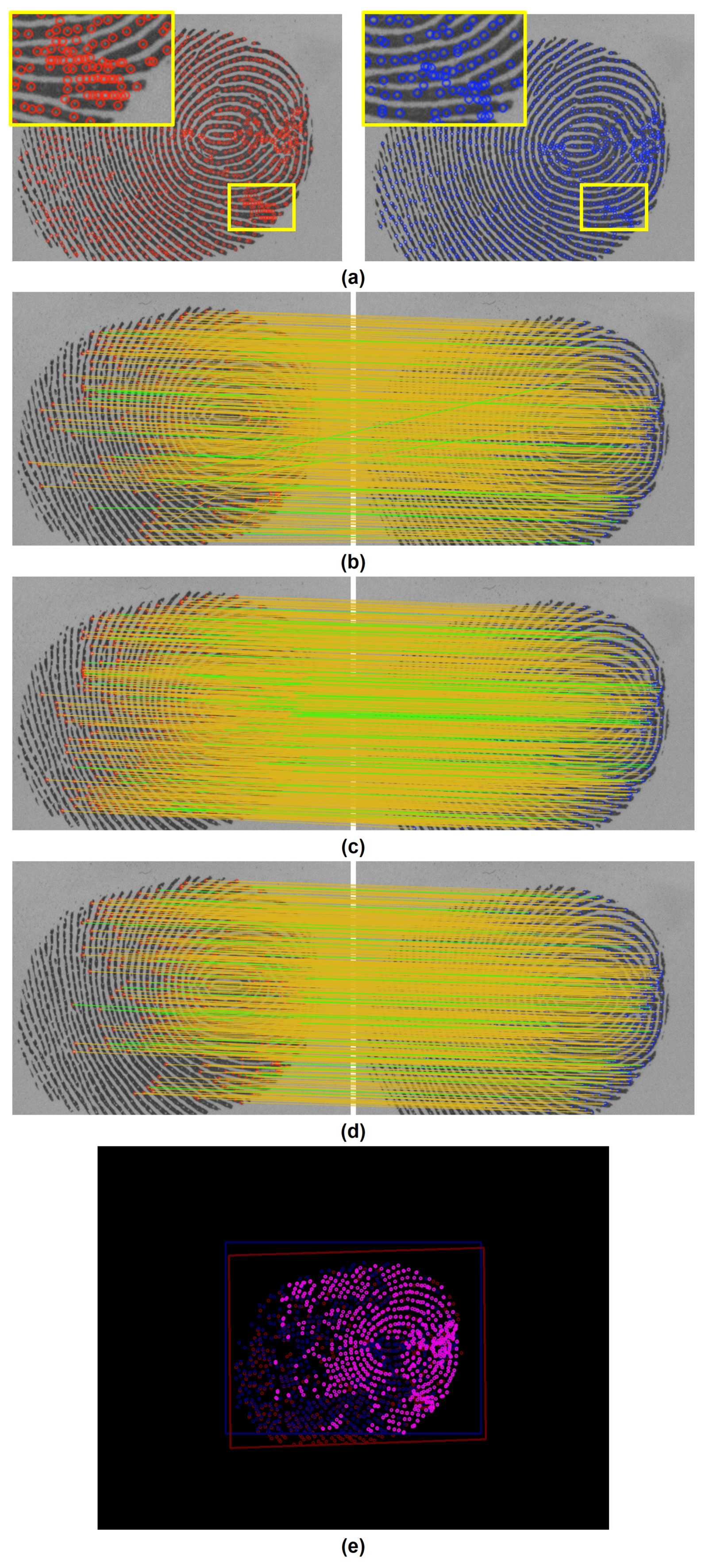
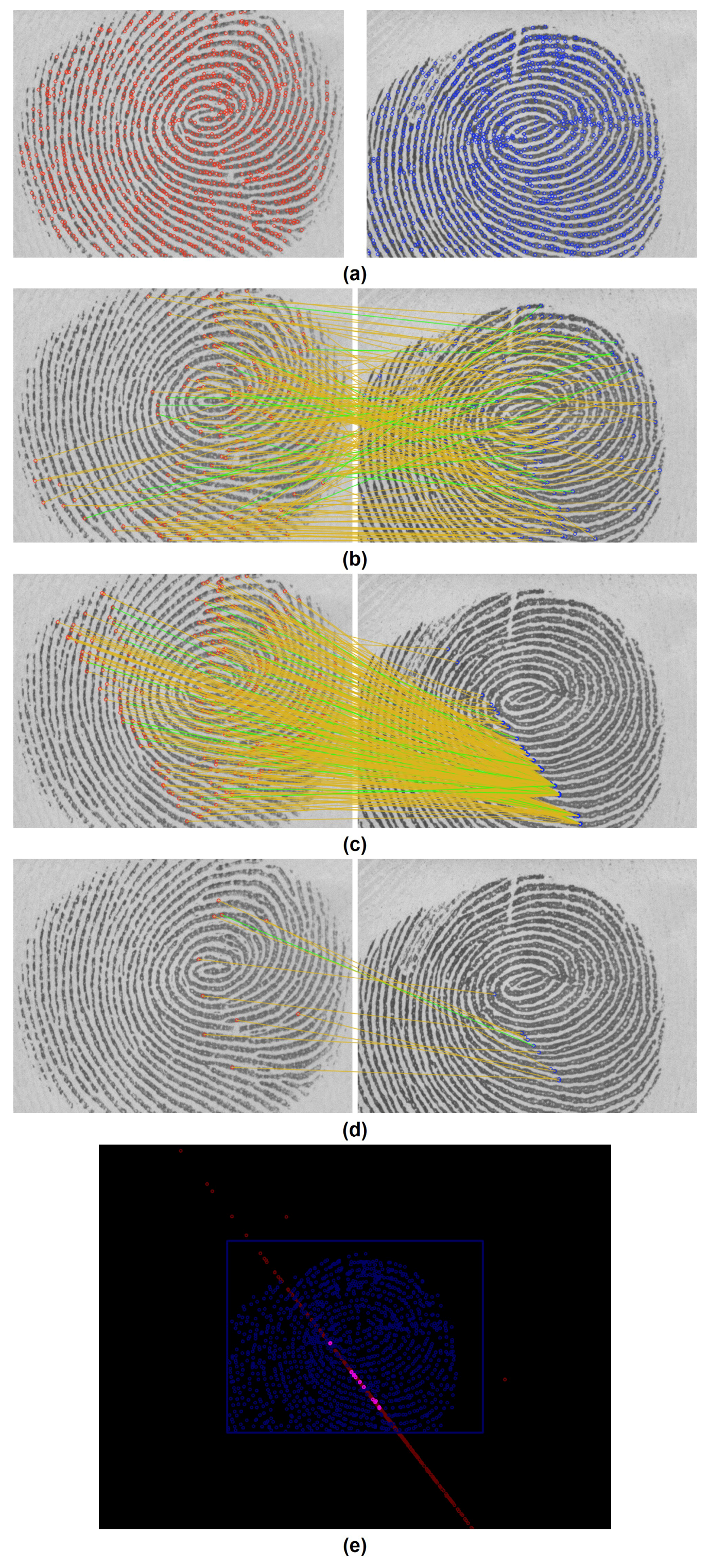
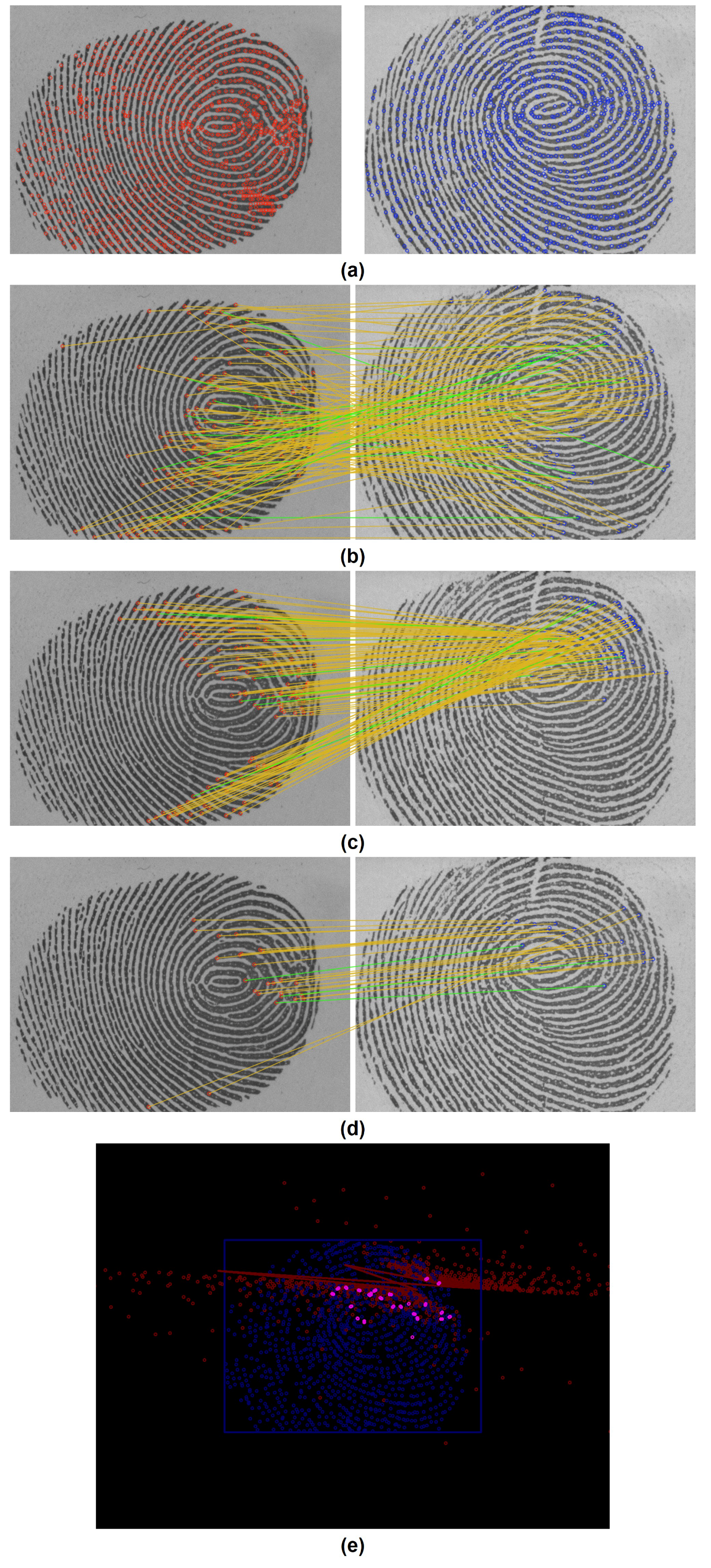
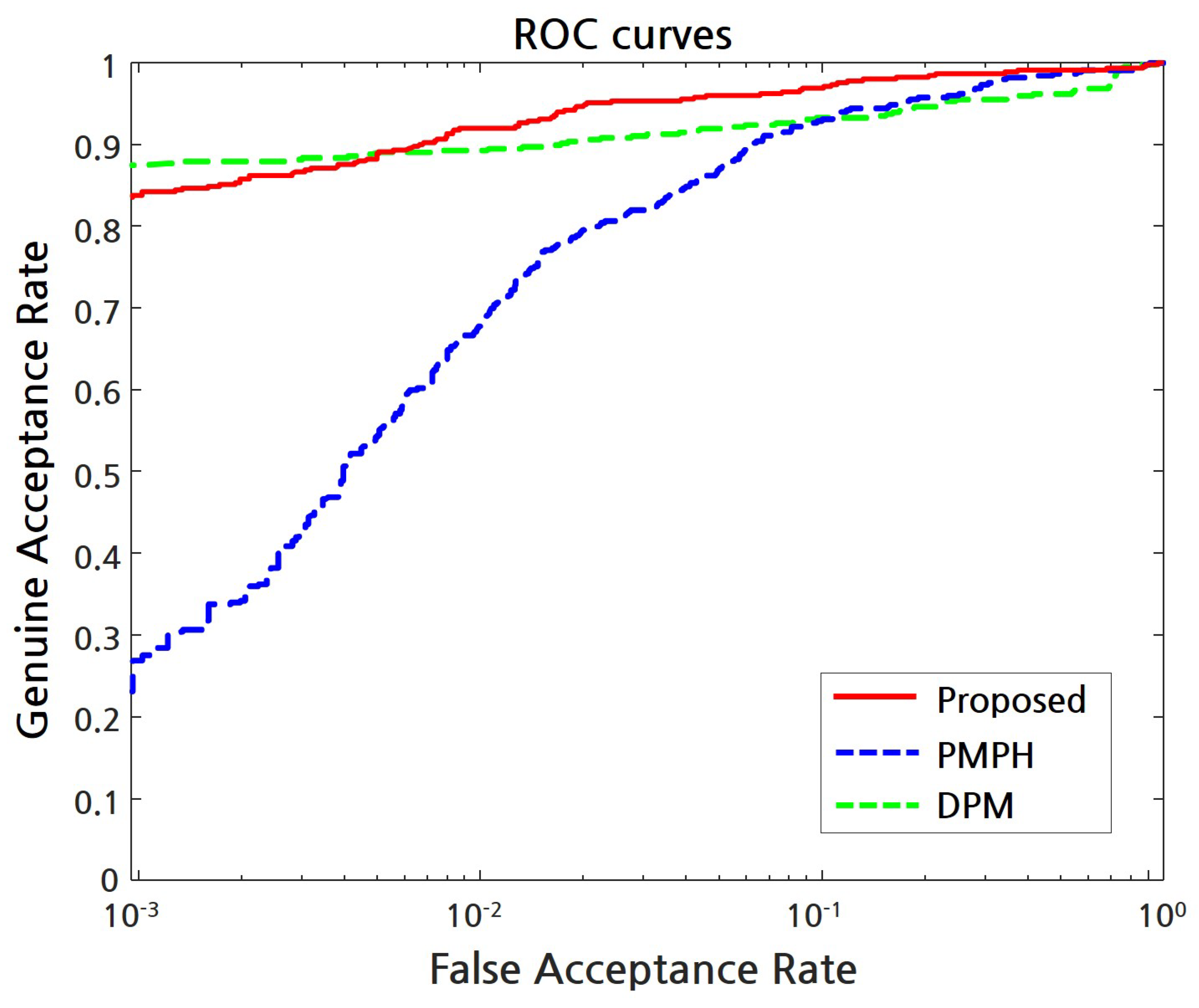
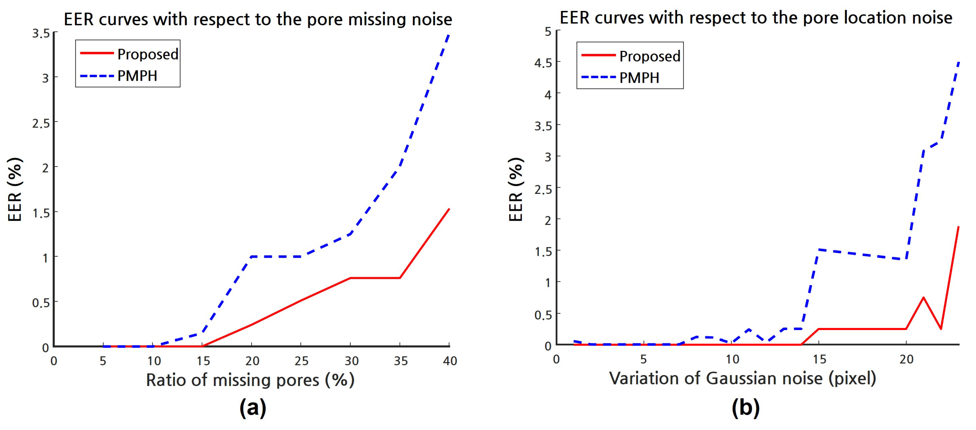
4. Experimental Results

This section presents experimental results to demonstrate the performance of the proposed pore matching algorithm using PolyU HRF database and in-house synthetic database.

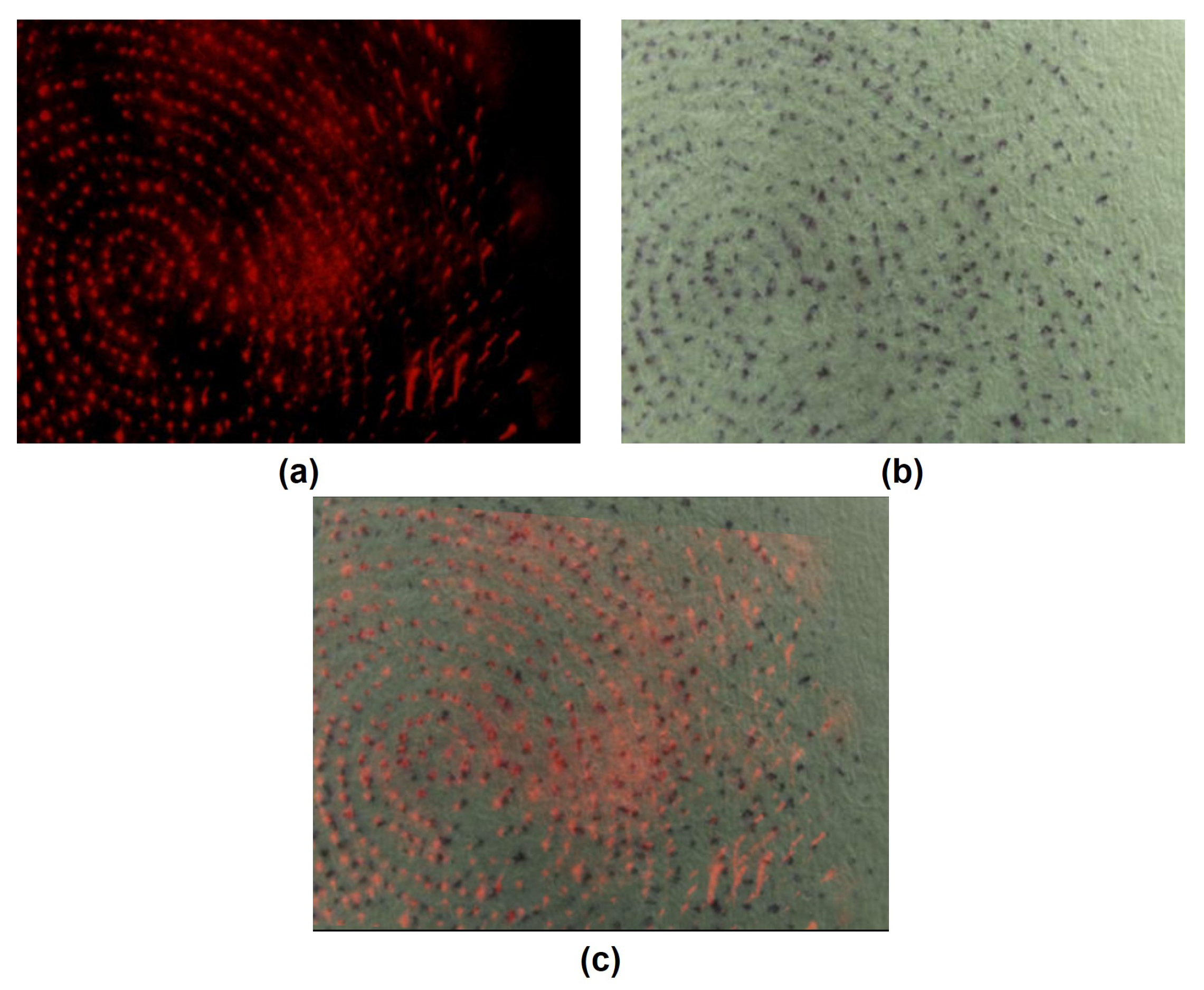
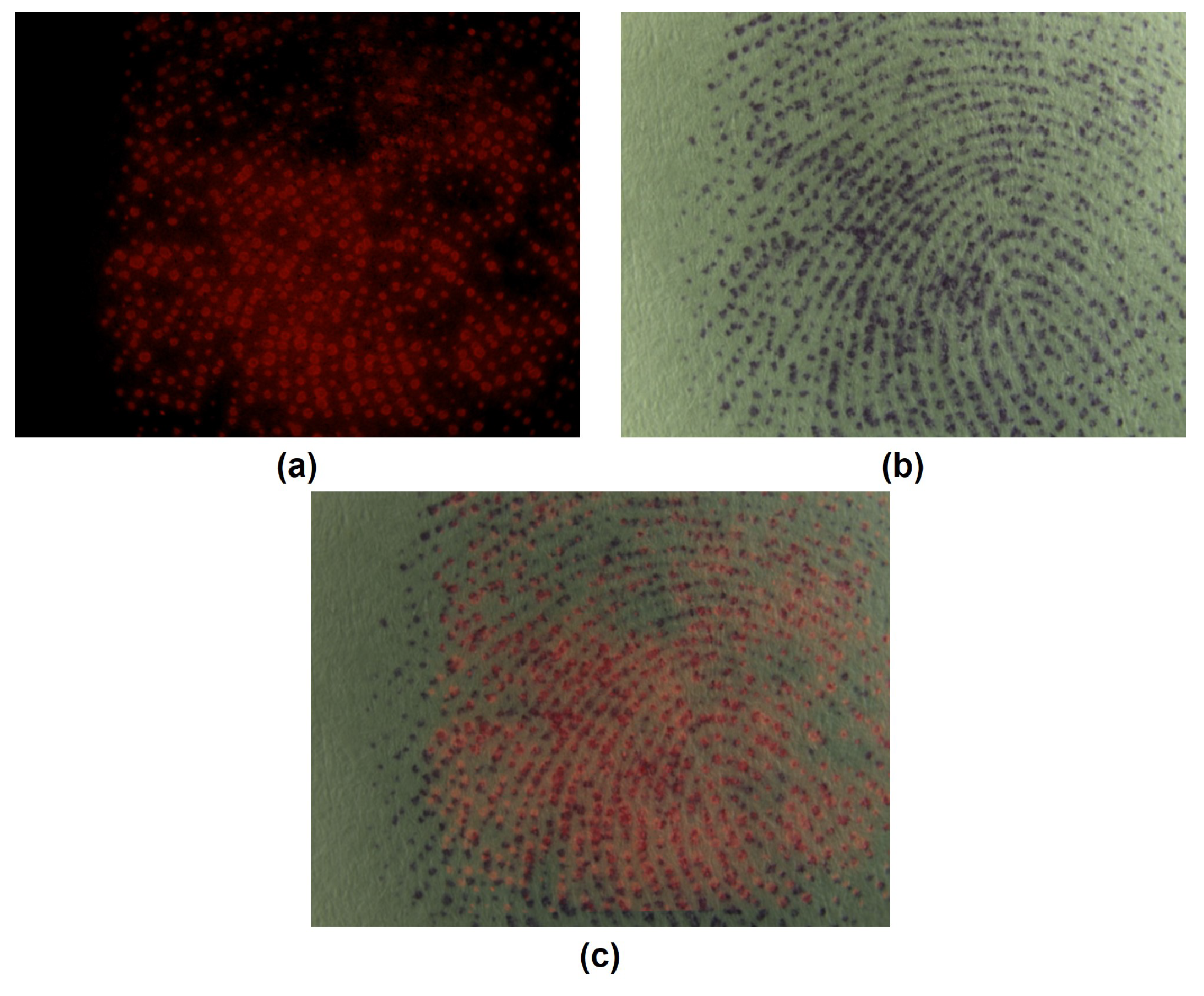
4.1. PolyU HRF Database

In order to evaluate the pore matching performance on live-scan digital fingerprint images, we used fingerprint images from PolyU HRF database [16]. In this experiment, we implemented the pore extraction method proposed in [19]. More specifically, the ridge orientation and mask are first obtained, and the pore candidates are extracted using simple 3 × 3 and 5 × 5 filters. For these candidates, the pore center locations are then estimated by fitting Cui’s 1D Gaussian pore model. Based on the pore extraction results, we noticed that the pore extraction has a significant influence on accuracy than matching since the pore extraction was poorly performed on some fingerprints in PolyU HRF database, as shown in Figure 7. To reduce this effect of pore extraction, 180 fingerprints were selected from PolyU HRF database. These fingerprint images were obtained from 30 fingers, and each finger produced six fingerprint images. More specifically, three of them were captured in the same week, and the remaining three were captured after two weeks. All 180 fingerprints were matched in a pairwise manner. Therefore, the number of genuine and imposter matches are respectively 900 and 31,320 in this setting.
Some example results of the proposed pore matching algorithm are shown in Figure 8, Figure 9, Figure 10, Figure 11 and Figure 12. Note that the pore extraction results using the method described in [19] have a certain amount of error as shown in Figure 8a. As shown in the matching results of Figure 8, Figure 9 and Figure 10, the local correspondences may include some outliers, which are removed in the final matching state. On the contrary, as shown in Figure 11 and Figure 12, the global correspondences could be unstable especially for the imposter cases, which can also be improved in the final matching state. As a result, Figure 8, Figure 9 and Figure 10 show that the proposed pore matching method can be effectively used for personal identification under noisy conditions including rotation, translation, truncation, and extraction error.
In this experiment, the direct pore matching method (DPM) [13] and polar histogram-based pore matching method (PMPH) [15] were also implemented and compared with the proposed pore matching method. For a fair comparison, our implementation of the pore extraction method proposed in [19] was commonly used. The equal error rates (EER) and false match rates 1000 (FMR1000) are given in Table 2. The receiver operating characteristic (ROC) curves for the proposed and existing methods are shown in Figure 13. As a result, the proposed method obtains the lowest EER and gets the slightly higher FMR1000 than DPM. Recall that DPM exploits more information such as the ridge orientation and the pixel intensity distribution. Compared with minutia-ridge and fingerprint-device independent method (PMPH), the proposed method improves the EER and FMR1000 by 47.5 % and 77.5 % , respectively.

4.2. Synthetic Database

In this experiment, in order to analyze the recognition accuracy according to noise, we generated some 290 synthetic pore fingerprints by controlling the noise level. We consider two types of noise: (i) the pore missing noise and (ii) location noise. To design a plausible experiment, we first extracted 20 ridge patterns from PolyU HRF database, and then randomly scattered about 1000 pores ( N ( 1000 , 10 2 ) ) upon the extracted ridges, which results in 20 original synthetic pore images with 640 × 480 resolution. For each level of noise, five noisy variants are generated. In other words, 100 noisy pore images are created per each noise level. For the pore missing noise, sweat pores are randomly removed By controlling the ratio of missing pores. All pore missing variants have different ways of missing sweat pores. This means that some sweat pores on one side may not be on the other sides. Thus, this is similar to the generation of false positives. For the pore location noise, the additive Gaussian noise with zero mean is added to each pore location by controlling the variance. In addition, all variant fingerprints are also randomly scaled and rotated. For each level of noise, all noisy variants were matched in a pairwise manner. The EER curves of the proposed method and PMPH with respect to two types of noise are presented in Figure 14. Our method outputs 1 % on EER after 37 % missing of pores and σ = 23 of the additive Gaussian noise, but PMPH goes beyond at 20 % missing of pores and σ = 14 of the additive Gaussian noise. In the extreme case of 50 % missing pores and additive Gaussian noise with zero mean and σ = 50 , the proposed method and PMPH respectively produced EER of 16.46 % and 20.17 % .

4.3. Pore-Based Fingerprint Image

As mentioned in Section 2, sweat pores can also be collected using the pore-based fingerprint imaging systems [9,10]. Thus, we applied the proposed method to match two different types of pore-based fingerprints, and the results are shown in Figure 15 and Figure 16. it is hard to analyze the pore matching accuracy in this experiment due to the small amount of available data, but note that the proposed method can be applied to various systems, where two sets of pore images separately come from different acquisition systems. In this experiment, the pore extraction method described in [9] was used.

5. Conclusions

In this work, we present a novel pore matching method using optimum geometric transformation and bipartite graph-based approach. Since the proposed method utilizes only pores location for the pore feature descriptor, we can successfully remove both the minutia-ridge and fingerprint-device dependencies. By reducing this minutia-ridge dependency, we expect that the proposed system will help enhance the performance of AFIS combined with the minutiae matching result. Unlike other features on the fingerprints, sweat pores can also be observed by the pore-based fingerprint systems. Thus, by removing the fingerprint-device dependency, the pore-based AFIS will be more useful for wider applications. Experiments show that the proposed method is better on EER and more stable under noisy conditions as compared to other existing methods. As a result, the proposed pore matching algorithm can be applied to broad applications including forensic science, which matches the latent fingerprint to the fingerprint image in databases. In the future, we hope to design a robust pore extraction method based on the machine learning algorithm.

Author Contributions

Investigation, M.-j.K.; Methodology, M.-j.K.; Validation, W.-Y.K.; Writing—review & editing, J.P.

Acknowledgments

This work was supported by the Chung-Ang University Excellent Student Scholarship in 2016 and by the Institute for Information and communications Technology Promotion (IITP) grant funded by the Korean government(MSIT) (2017-0-00250, Intelligent Defense Boundary Surveillance Technology Using Collaborative Reinforced Learning of Embedded Edge Camera and Image Analysis). Without support for the PolyU HRF database, this research would have been diminished.

Conflicts of Interest

The authors declare no conflict of interest.

References

  1. Maltoni, D.; Maio, D.; Jain, A.; Prabhakar, S. Handbook of Fingerprint Recognition; Springer Science & Business Media: Heidelberg/Berlin, Germany, 2009. [Google Scholar]
  2. Ratha, N.; Bolle, R. Automatic Fingerprint Recognition Systems; Springer Science & Business Media: Heidelberg/Berlin, Germany, 2007. [Google Scholar]
  3. Pankanti, S.; Prabhakar, S.; Jain, A.K. On the individuality of fingerprints. IEEE Trans. Pattern Anal. Mach. Intell. 2002, 24, 1010–1025. [Google Scholar] [CrossRef]
  4. Zhang, D.; Liu, F.; Zhao, Q.; Lu, G.; Luo, N. Selecting a reference high resolution for fingerprint recognition using minutiae and pores. IEEE Trans. Instrum. Meas. 2011, 60, 863–871. [Google Scholar] [CrossRef]
  5. Jain, A.K.; Chen, Y.; Demirkus, M. Pores and ridges: High-resolution fingerprint matching using Level 3 features. IEEE Trans. Pattern Anal. Mach. Intell. 2007, 29, 15–27. [Google Scholar] [CrossRef] [PubMed]
  6. Ashbaugh, D. Poroscopy. Identif. News 1982, 32, 3–8. [Google Scholar]
  7. Zhao, Q.; Jain, A.K. On the utility of extended fingerprint features: a study on pores. In Proceedings of the 2010 IEEE Computer Society Conference on Computer Vision and Pattern Recognition-Workshops, San Francisco, CA, USA, 13–18 June 2010; pp. 9–16. [Google Scholar]
  8. Roddy, A.R.; Stosz, J.D. Fingerprint features-statistical analysis and system performance estimates. Proc. IEEE 1997, 85, 1390–1421. [Google Scholar] [CrossRef]
  9. Lee, J.; Pyo, M.; Lee, S.H.; Kim, J.; Ra, M.; Kim, W.Y.; Park, B.J.; Lee, C.W.; Kim, J.M. Hydrochromic conjugated polymers for human sweat pore mapping. Nat. Commun. 2014, 5, 3736. [Google Scholar] [CrossRef] [PubMed]
  10. Elsner, C.; Abel, B. Ultrafast High-Resolution Mass Spectrometric Finger Pore Imaging in Latent Finger Prints. Sci. Rep. 2014, 4, 6905. [Google Scholar] [CrossRef] [PubMed]
  11. Stosz, J.D.; Alyea, L.A. Automatic Systems for the Identification and Inspection of Humans; International Society for Optics and Photonics: Bellingham, WA, USA, 1994; Volume 2277, pp. 210–224. [Google Scholar]
  12. Kryszczuk, K.; Drygajlo, A.; Morier, P. Extraction of Level 2 and Level 3 Features for Fragmentary Fingerprint Comparison; Speech Processing and Biometrics Group, Signal Pro-cessing Institute, Swiss Federal Institute of Technology Lausanne: Lausanne, Switzerland, 2004. [Google Scholar]
  13. Zhao, Q.; Zhang, L.; Zhang, D.; Luo, N. Direct Pore Matching for Fingerprint Recognition; Springer: Heidelberg/Berlin, Germany, 2009; pp. 597–606. [Google Scholar]
  14. Liu, F.; Zhao, Q.; Zhang, L.; Zhang, D. Fingerprint Pore Matching Based on Sparse Representation; Indian Council of Philosophical Research: New Delhi, India, 2010; pp. 1630–1633. [Google Scholar]
  15. Cui, J.; Ra, M.S.; Kim, W.Y. Fingerprint pore matching method using polar histogram. In Proceedings of the 18th IEEE International Symposium on Consumer Electronics (ISCE 2014), JeJu Island, Korea, 22–25 June 2014; pp. 1–2. [Google Scholar]
  16. PolyU HRF Database. Available online: http://www4.comp.polyu.edu.hk/~biometrics/ (accessed on 19 May 2018).
  17. Ray, M.; Meenen, P.; Adhami, R. A novel approach to fingerprint pore extraction. In Proceedings of the Thirty-Seventh Southeastern Symposium on System Theory, Tuskegee, AL, USA, 20–22 March 2005; pp. 282–286. [Google Scholar]
  18. Zhao, Q.; Zhang, D.; Zhang, L.; Luo, N. Adaptive fingerprint pore modeling and extraction. Pattern Recognit. 2010, 43, 2833–2844. [Google Scholar] [CrossRef]
  19. Cui, J.; Ra, M.; Kim, W.Y. Fingerprint Pore Extraction Method using 1D Gaussian Model. J. Inst. Electr. Inf. Eng. 2015, 52, 135–144. [Google Scholar] [CrossRef]
  20. Fischler, M.A.; Bolles, R.C. Random sample consensus: A paradigm for model fitting with applications to image analysis and automated cartography. Commun. ACM 1981, 24, 381–395. [Google Scholar] [CrossRef]
  21. Moré, J.J. the Levenberg-Marquardt algorithm: implementation and theory. In Numerical Analysis; Springer: Heidelberg/Berlin, Germany, 1978; pp. 105–116. [Google Scholar]
  22. Pujol, J. the solution of nonlinear inverse problems and the Levenberg-Marquardt method. Geophysics 2007, 72, W1–W16. [Google Scholar] [CrossRef]
  23. Gusfield, D.; Irving, R.W. The Stable Marriage Problem: Structure and Algorithms; MIT Press: Cambridge, UK, 1989. [Google Scholar]
  24. Manlove, D.F.; Irving, R.W.; Iwama, K.; Miyazaki, S.; Morita, Y. Hard variants of stable marriage. Theor. Comput. Sci. 2002, 276, 261–279. [Google Scholar] [CrossRef]
  25. Iwama, K.; Miyazaki, S. A survey of the stable marriage problem and its variants. In Proceedings of the 2008 International Conference on Informatics Education and Research for Knowledge-Circulating Society, Kyoto, Japan, 17 January 2008; pp. 131–136. [Google Scholar]
Figure 1. High-resolution fingerprint image in PolyU HRF database [16]. Red and yellow circles respectively mark some of the open and closed pores.
Symmetry 10 00175 g001
Figure 2. Fluorescence fingerprint image (reprinted by permission from Macmillan Publishers Ltd.: Nature Communications [9], copyrights 2014).
Symmetry 10 00175 g002
Figure 3. Flowchart of the proposed pore matching method.
Symmetry 10 00175 g003
Figure 4. Example of a generated polar histogram with three distance bins and eight angular bins: (a) a circle including the center point and its adjacent points; (b) the number of residing points in each bin and (c) the generated polar histogram.
Symmetry 10 00175 g004
Figure 5. Local similarity matrix construction process.
Symmetry 10 00175 g005
Figure 6. Experimental results of the global correspondences: (a) with and (b) without using the LMA refinement. 10 % of correspondences are randomly marked as green.
Symmetry 10 00175 g006
Figure 7. Pore extraction example: (a) a fingerprint image of PolyU HRF database and (b) the pore extraction result.
Symmetry 10 00175 g007
Figure 8. Experimental results of the proposed pore matching algorithm for genuine match: (a) results of the pore extraction using the method described in [19]; (b) the local correspondences; (c) the global correspondences; (d) results of the final matching and (e) a superimposed image of two sweat pore fingerprints based on the final matching.
Symmetry 10 00175 g008
Figure 9. Experimental results of the proposed pore matching algorithm for genuine match: (a) results of the pore extraction using the method described in [19]; (b) the local correspondences; (c) the global correspondences; (d) results of the final matching and (e) a superimposed image of two sweat pore fingerprints based on the final matching.
Symmetry 10 00175 g009
Figure 10. Experimental results of the proposed pore matching algorithm for genuine match: (a) results of the pore extraction using the method described in [19]; (b) the local correspondences; (c) the global correspondences; (d) results of the final matching and (e) a superimposed image of two sweat pore fingerprints based on the final matching.
Symmetry 10 00175 g010
Figure 11. Experimental results of the proposed pore matching algorithm for imposter match: (a) results of the pore extraction using the method described in [19]; (b) the local correspondences; (c) the global correspondences; (d) results of the final matching and (e) a superimposed image of two sweat pore fingerprints based on the final matching.
Symmetry 10 00175 g011
Figure 12. Experimental results of the proposed pore matching algorithm for imposter match: (a) results of the pore extraction using the method described in [19]; (b) the local correspondences; (c) the global correspondences; (d) results of the final matching and (e) a superimposed image of two sweat pore fingerprints based on the final matching.
Symmetry 10 00175 g012
Figure 13. ROC curves for the proposed method, DPM, and PMPH.
Symmetry 10 00175 g013
Figure 14. EER curves for the proposed method and PMPH with respect to two types of noise: (a) the pore missing noise and (b) the pore location noise.
Symmetry 10 00175 g014
Figure 15. Sweat pore matching on a fluorescence fingerprint image and a latent fingerprint image of the same donor: (a) a fluorescence microscopic fingerprint image; (b) a latent fingerprint image using Ninhydrin and (c) the superimposed result of two fingerprints based on the final matching.
Symmetry 10 00175 g015
Figure 16. Sweat pore matching on a fluorescence fingerprint image and a latent fingerprint image of the same donor: (a) a fluorescence microscopic fingerprint image; (b) a latent fingerprint image using Ninhydrin, and (c) the superimposed result of two fingerprints based on the final matching.
Symmetry 10 00175 g016
Table 1. The projective transformation matrix, its parameter vector, the Jacobian matrix of the algebraic distance with respect to the parameter, and the degree-of-freedom.
NameProjective Transformation
Matrix (M) m 00 m 01 m 02 m 10 m 11 m 12 m 20 m 21 1
Parameter (m) m 00 m 01 m 02 m 10 m 11 m 12 m 20 m 21 T
Jacobian (J) 1 m 20 x r + m 21 y r + 1 x r y r 1 0 0 0 x r x t y r x t 0 0 0 x r y r 1 x r y t y r y t
Degree-of-freedom8
Table 2. The recognition accuracy of three pore matching methods.
MethodDPMPMPHProposed
EER 7.16 % 8.08 % 4.24 %
FMR1000 12.44 % 73.11 % 16.44 %

