Mineral Sequestration of Carbon Dioxide in Circulating Fluidized Bed Combustion Boiler Bottom Ash

Department of Civil and Environmental Engineering, Korea Advanced Institute of Science and Technology, 291 Daehak-ro, Yuseong-gu, Daejeon 34141, Korea
*
Author to whom correspondence should be addressed.
Minerals 2017, 7(12), 237; https://doi.org/10.3390/min7120237
Submission received: 11 September 2017
/
Revised: 3 November 2017
/
Accepted: 27 November 2017
/
Published: 29 November 2017
(This article belongs to the Special Issue Carbon Capture and Storage via Mineral Carbonation)
Abstract
:This paper investigates the mineral sequestration of carbon dioxide in circulating fluidized bed combustion (CFBC) boiler bottom ash. CFBC bottom ash, which originated from two sources, was prepared along with pulverized coal-fired (PC) boiler bottom ash as a control. These ashes were exposed to accelerated carbonation conditions at a relative humidity of 40% and 100%, in order to investigate the effects of humidity on the carbonation kinetics of the bottom ash. The obtained results showed that not only lime but other calcium-bearing phases (gehlenite, wollastonite, and brownmillerite) in CFBC bottom ash participated in the mineral carbonation reaction. In particular, these phases underwent hydration in a wet carbonation environment, whereby the carbon dioxide uptake and capacity of CFBC bottom ash are significantly enhanced. This study may have important implications, demonstrating the feasibility of carbon dioxide sequestration and recycling of CFBC boiler bottom ash.
1. Introduction
Increasing energy demand has become a global issue, which has led to the generation of pollutants and greenhouse gas discharged from power plants, causing environmental problems and climate change. Accordingly, carbon capture, utilization, and storage has become highly important to respond to climate change and abnormal temperature phenomena that is caused by global warming [1,2]. According to the United States (US). Energy Information Administration, coal is currently the largest source of fuel for electric power generation and coal-fired power plants comprise of 76% of CO2 emissions [3]. In addition, in the case of the United States and South Korea, only about 60% to 70% of the generated coal combustion ash is recycled, respectively and the remaining portion is dispensed in landfill and surface impoundments. Both methods are environmentally harmful due to the risk of exposing leachate containing heavy metals and harmful substances to the soil [4]. Despite these risks, power generation using coal sources occupied 40% of the world’s total electric power generation in 2012, and it is predicted to remain stationary until 2040 [5].
Circulating fluidized bed combustion (hereinafter, CFBC) boilers are a typically adopted technology in coal-fired power plants, which can rely on low-grade coal, utilizing combustion temperatures of 800–950 °C, which is 400–600 °C lower than that of pulverized coal-fired (hereinafter, PC) boilers (1200–1400 °C) [6]. The lower combustion temperature of CFBC boilers allows the usage of a wider range fuel types, even those with lower calorific values, which gives CFBC boilers a competitive advantage [7]. In addition, CFBC boilers emit less NOx when compared to conventional PC boilers, due to the lower combustion temperature, and desulfurization processes using limestone [8]. Therefore, the adoption of CFBC boilers as a means of power generation has experienced an increase in recent years due to the high thermal efficiency, and, the reduction in NOx and SOx emissions. The low combustion temperature (capable of utilizing low-grade coal of less than 6000 kcal) allows for an ideal coal-fired power plant that is able to meet the increasing energy demand of numerous countries [9]. In addition, as CFBC boilers are able to be utilized along with other energy sources, such as biomass and waste sludge, the use of CFBC boilers is expected to increase in the future [9].
Nevertheless, the by-products of CFBC power plants, mainly CFBC ash, remains a problem. Unlike typical PC boiler ash, CFBC ash does not meet the relevant standards for additives in concrete in Europe or North America, due to its high sulfur content [10]. Moreover, its high sulfur and free lime content often lead to swelling and destructive expansion, inhibiting its utilization in construction industries [11]. This is a significant issue that is anticipated to be of a greater concern in the future with the increased adoption of CFBC boilers, when considering that construction applications provide single largest use of coal ash [10,12]. Therefore, an alternative solution that enables the utilization of CFBC ash is urgently required to cope with the increasing demand of CFBC boilers and related by-products.
This paper suggests an option that is capable of mitigating both issues of CO2 emissions from coal-fired power plants by facilitating carbon capture, as well as the issues in utilizing CFBC ash, while studies of the carbonation characteristics of accompanying minerals are considered to have explored the potential of recycling CFBC ash. In addition, this study assesses CFBC bottom ash as a sorbent for carbon dioxide in flue gas, and presents the product and form of CO2 sequestrated in CFBC bottom ash.
Mineral carbonation can be applied to a variety of materials, as reported by a study that showed that cement wastes (kiln and bypass dust, and demolition wastes) could be an advantageous option for carbon dioxide sequestration in large scale due to their high contents of calcium [13,14]. Similarly, many studies were carried out to validate the effect of mineral carbonation on the coal ash. Studies on carbonation of PC ash has been carried out in order to accelerate the carbonation reaction at high temperature (~800 °C) and high concentration of CO2 (~99.9%) [15,16], and for the immobilization of heavy metals in coal ash through carbonation [17]. Some studies have used the brine solution to accelerate carbonation in PC ash and also CFBC ash [18,19,20]. Studies on carbonation of CFBC ashes are being actively conducted with an emphasis on carbon capture, storage and utilization.
Currently, there are three methods that can be applied for capturing carbon dioxide in coal fired power plants as follows: Separating carbon dioxide from flue gas (called post-combustion process), pre-combustion process to capture carbon dioxide before combustion, and oxy-fuel combustion process that captures carbon dioxide generated by injecting oxygen and coal combustion [21,22]. As a solution for zero emission, calcium looping technology is newly proposed to sequestrate carbon dioxide through the decomposition of calcite into calcium oxide and carbon dioxide [23]. CFBC reactors with calcium-looping technology are installed in various scales, and are under development [24], which may avail CFBC ash as CO2 sorbent via the accelerated carbonation process. In addition, studies on the oxygen transport mass balance in the CFBC environment through the calcium-looping combustion technology have also been conducted [25].
Though the post-combustion process has the advantage of the capability to be installed in existing boilers, coal-fired power plants that apply post-combustion technology produces flue gas with CO2 concentrations of 4% to 15%, depending on the fuel [22,26], which is low when compared to flue gas produced from the pre-combustion process (greater than 20%), and the oxy-fuel combustion process (from 80% to 98%) [27,28].
The flue gas should be condensed in order to capture CO2 effectively from flue gas with lower CO2 concentrations, or a relatively greater amount of gas should be stored, as these methods have several issues, such as difficulty in transportation [22,26,29]. Therefore, the technology is required for the sequestrating and utilization of low concentrations of CO2 in flue gas.
Studies of mineral carbonation have been conducted on adoption of various materials, as well as using CFBC ash for CO2 sequestration. However, most studies were conducted in environments where high CO2 concentrations are available. For instance, Loo et al. [30] conducted accelerated wet carbonation experiments on CFBC bottom ash, CFBC cyclone ash, and CFBC filter ash (each prepared solution possessed an ash-to-water ratio of 1:10, and a pH of up to 7) using pure CO2 gas. It was found that an average of 0.081 tons of carbon dioxide is captured per ton of ash. Rao et al. [31] performed carbon capture with CFBC ash and pure CO2 gas through sonochemical treatment at temperatures of between 20 and 80 °C. It was confirmed that the conversion rate of CaO is high at high temperatures during the carbonation reaction. Wang et al. [16] calculated the carbonation activation energy, and CaO carbonation conversion ratio of CFBC fly ash at temperatures of 250 to 850 °C, and H2O levels of 0%, 8%, and 15% using CO2 gas of 80% concentration, and confirmed that CaO carbonation occurs at high temperatures, as well as at high H2O levels.
Studies on low-grade coal fuel (Estonian oil-shale) using CFBC boiler ash at low levels of carbon dioxide were conducted in a wet carbonation condition using waste water from PC bottom ash, intrex ash at 10% and 15% CO2, and water at 10% CO2, respectively. The obtained results showed that it is possible to capture 52 kg and up to a maximum of 160 kg of CO2 per ton of ash, respectively [32]. It should be noted that only a limited number of studies were conducted in regards to CO2 sequestration in CFBC bottom ash at a low concentration of CO2. In addition, bottom ash generally possesses a larger particle size than that of fly ash, has an irregular shape, and its chemical characteristic significantly vary according to its particle size [33]. Therefore, this study examines the mineral carbonation of CFBC bottom ash with uniform particle size in various humidity environments at low CO2 concentration (10%) in order to match the average CO2 concentration in actual boilers. Total inorganic carbon measurement and XRD Rietveld method were adopted to quantify the amount of CO2 sequestration, furthermore, the morphology of CFBC bottom ash that underwent carbonation was explored. In addition, this study explores the carbonation of CaO and Ca-bearing phases using the XRD Rietveld method. Morphology was simultaneously observed, providing evidence for the potential application of CFBC bottom ash in coal-fired power plants for carbon capture, utilization, and storage (CCUS). In contrast to the criticisms centered in debates and discussions on the safety and cost of current CCS technology, this technology may result in significantly reduced operating costs. In addition, the utilization of CFBC ash produced from the combustion of low concentration CO2 as carbonated aggregates or in concrete opens opportunities for potentially important future research regarding the use of low concentration CO2.
2. Materials and Methods
2.1. Materials Used and Sample Preparation
Three types of bottom ash were used to investigate the effects of the chemical and physical characteristics of the ashes on their CO2 sequestration capacity. These included two types of CFBC bottom ash and one type of PC bottom ash, each were collected from a different site, as follows:
- CFBC bottom ash: Two samples were prepared using the bottom ash obtained from the Yeosu power plant in South Korea (‘hereinafter, C1’), and the other from the Gunsan plant (‘hereinafter, C2’). Both were bottom ash generated from a CFBC boiler.
- PC bottom ash: One sample was prepared using PC boiler bottom ash obtained from the Seocheon power plant in South Korea (hereinafter, P1).
The following procedure was undertaken to ensure that the particle size of the bottom ash that were used in the sample preparation was uniform: C1, C2, and P1 were sieved into 0.15 mm–0.25 mm and 0.25 mm–0.425 mm samples using sieves with diameters of 0.15 mm, 0.25 mm, and 0.425 mm. A sample mix was prepared for each of the three types of bottom ash by mixing the 0.15 mm–0.25 mm diameter bottom ash sample with the 0.25 mm–0.425 mm diameter bottom ash sample in a 1:1 mass ratio.
Note that the particle size of a bottom ash significantly varies, which can be a factor influencing its adsorption characteristic. Hence, this study employed bottom ash with a fine fraction of 0.425 mm. Since the particle size of the bottom ash showed a high distribution below a particle size of 0.425 mm, the mesh size was chosen based on its two highest particle size distribution. In addition, the particle size was kept as consistent as possible by choosing those falling below 0.425 mm.
2.2. Experimental Details
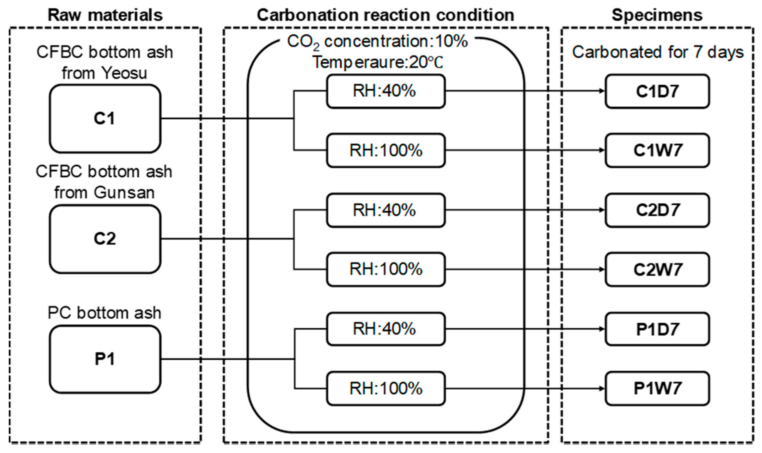
The sample preparation and carbonation conditions are described in Figure 1. Each of the three types of bottom ash (C1, C2, and P1) with uniform particle size were evenly spread on separate trays to maximize the carbonation rate and to ensure that the rate was steady. Two different humidity conditions were investigated as follows. For one set (Set 1), water was poured into the tray at a volume of twice the mass of the sample mix in order to set the relative humidity of the sample mix at 100% (“wet carbonation”), while no water was added to the other set (Set 2) (“dry carbonation”). Hence, the Set 2 samples were only exposed to the relative humidity of the chamber (40%). The CO2 concentration inside the carbonation chamber was set and maintained at 10% by continuously flowing carbon dioxide gas into the chamber. The temperature in the chamber was maintained at 20 °C. The samples were allowed to be carbonated for seven days under the constant temperature and humidity conditions.
The chemical compositions of C1, C2, and P1 that were used in this study were analyzed with an X-ray fluorescence (XRF) technique, using a MiniPal 2 (PANanalytical, Nottingham, UK). Free CaO indicates unreacted CaO during the combustion process, which would then be readily available for carbonation. This should not be confused with the elemental mass obtained by XRF given as oxides mass ratio. The amount of free CaO in each of the bottom ashes was measured before carbonation. Uncombined CaO (unreacted CaO) was measured by using diluted perchloric acid and titrating. The amount of free CaO (%) was calculated in accordance with ASTM C114-13 [34].
The surface morphology of the samples upon carbonation was investigated by means of a scanning electron microscopy (SEM), as well as Brunauer-Emmett-Teller (BET) surface area analysis. Specimens were coated with osmium before the SEM images were taken with the Magellan 400 device (FEI Company, Hillsboro, OR, USA). A Tristar II 3020 (Micromeritics company, Norcross, GA, USA) was used for the BET surface area analysis at 77.3 K. The amount of CO2 uptake in the carbonated samples was quantified by means of a total inorganic carbon (TIC) test and the Rietveld X-ray diffraction (XRD) refinement method.
TIC tests were conducted using an EA 1108 CHNS-O instrument (FISONS Company, Ipswich, UK). The sample was instantaneously burned and oxidized in a high-temperature pure oxygen atmosphere. The resulting gas mixture was separated into individual components in a separation tube, and then detected using a thermal conductivity detector to determine the total amount of carbon and organic carbon. The TIC test measures the total amount of inorganic carbon species (i.e., carbon dioxide, carbonic acid, bicarbonate anions, and carbonate, etc.) by subtracting the total amount of organic carbon from that of the carbon that is present in the sample, as expressed in Equation (1) [35].
TIC (Total Inorganic Carbon) = TC (Total Carbon) − TOC (Total Organic Carbon)
The XRD Rietveld refinement analysis quantifies the chemical compounds that are present in the samples unlike a typical XRD analysis. A powder sample, with which it is easy to search for its peak of standard sample, is chosen as an internal standard. Its ratio of the integrated intensities of its peaks is used to quantify the chemical compounds. In the present study, SiO2 powder was used as an internal standard for the XRD Rietveld refinement analysis [36].
The total amount of inorganic carbon in the carbonated samples was measured on the seventh day of the carbonation reaction. The amount of inorganic carbon was measured using the flash dynamic combustion method and the elemental analyzer EA1108 (FISONS Company, Ipswich, UK). The XRD was performed using an Empyrean high-resolution X-ray diffractometer (HR-XRD), manufactured by PANalytical (Nottingham, UK) with a scan range from 5° to 90° 2θ.
3. Results
3.1. Characterization of Raw Bottom Ash
The chemical compositions and amounts of free CaO of C1, C2, and P1 are presented in Table 1. The main components of the C1, C2, and P1 samples were Fe2O3, SiO2, and Al2O3, while the CaO contents of CFBC bottom ash samples (C1, C2) were higher than that of the PC bottom ash sample (P1). The CaO content of the C1, C2, P1 samples was 47.6%, 52.7%, and 2.1%, respectively. The large amount of CaO in the CFBC boiler bottom ash can be attributed to the addition of limestone for the reduction of SO2 emissions in a CFBC boiler [8]. Meanwhile, the free CaO contents in the C1, C2, and P1 samples were 0.61%, 4.94%, and 0.04%, respectively. This indicates that the content of reactive CaO in the C1 sample was similar to that of the P1 sample.
3.2. CO2 Sequestration in Bottom Ash
This study utilized two methods to quantify the CO2 that was sequestrated in the bottom ash. First, CO2 sequestration was estimated using the total inorganic carbon (TIC) test. Second, the XRD Rietveld refinement method was used to quantitatively measure the amount of CO2 sequestrated after the carbonation process, along with other hydration products (in the case of wet carbonation).
The TIC results of pre-carbonation, dry-carbonation, and wet-carbonation samples are shown in Table 2.
The amount of CO2 sequestrated in the bottom ash samples quantified using TIC analysis was calculated as expressed in Equation (2), and the corresponding results are shown in Figure 2.
CO2 sequestrated ratio (%) = TIC post-carbonation (%) − TIC pre-carbonation (%)
It is evident that the CFBC bottom ash samples exhibited a greater carbon storage capacity in high-humidity environments due to the following chain of reactions [35].
CaO(s) + H2O(aq) → Ca(OH)2(aq)
Ca(OH)2(aq) + CO2(g) → CaCO3↓(s) + H2O(l)
It suggests that the presence of water plays an essential role in hydrating the free lime to form calcium hydroxide, which can then sequestrate carbon by forming calcium carbonate under an accelerated carbonation condition. In the case of pulverized coal-fired boiler bottom ash, P1 has a high standard deviation value and already had a high TIC value before carbonation. The pulverized coal bottom ash that was used in this study contained high inorganic matter, not necessarily due to unburned carbon, but owing to other combustion process [37]. The CO2 sequestration ratio is obtained by subtracting TIC pre-carbonation (%) from TIC post-carbonation (%). The CO2 sequestration ratio of P1 has a similar absolute value, however, the pre-carbonation (%) value (i.e., initial value) is relatively larger than C1 and C2, and can be regarded as in the error range. Note that the P1 sample had a high error range and a relatively higher TIC value before carbonation, indicating a significant variation among the samples that were used. This may have caused an error that was carried forward in the rest of the calculations presented in Table 2 and as a negative value in Figure 2.
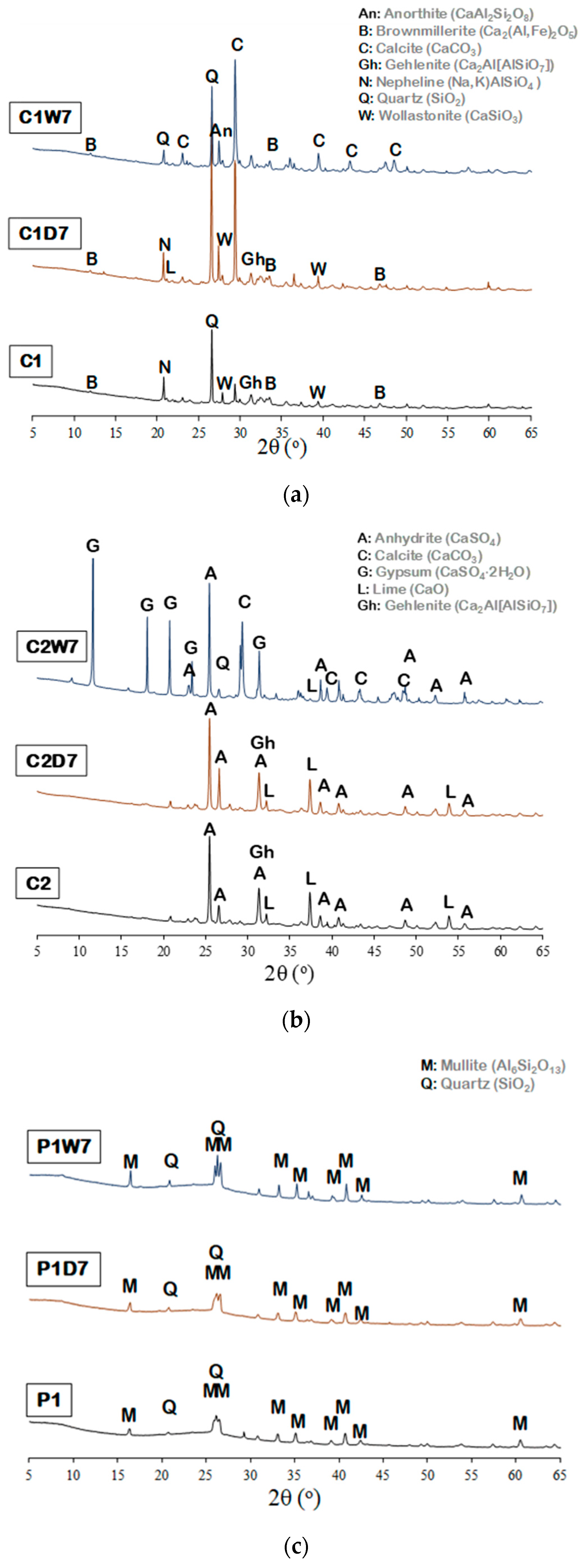
The amount of CO2 sequestrated in the bottom ash samples quantified using the XRD Rietveld refinement method is shown in Figure 3 and Table 3. The XRD pattern of the C1 sample showed peaks corresponding to quartz (SiO2), brownmillerite (Ca2(Al,Fe)2O5), gehlenite (Ca2Al(AlSiO7)), magnesite (MgCO3), and a minor quantity of calcite (CaCO3), lime (CaO), nepheline ((Na,K)AlSiO4), wollastonite (CaSiO3), and cristobalite (SiO2). The C2 sample showed a similar pattern, while the presence of anhydrite (CaSO4) and lime (CaO) was much more significant. Lastly, the P1 sample showed peaks due to the presence of mullite (Al6Si2O13) and quartz (SiO2), with a minor quantity of corundum (Al2O3).
It should be noted that the carbonation behavior and CO2 uptake were different in all three of the samples, according to the humidity conditions. In general, the highest amount of calcite was observed in C1W7 and C2W7, indicating that the wet condition is essential for promoting CO2 sequestration in CFBC bottom ash. Similarly, a lower degree of CO2 sequestration was observed in the sample that underwent dry carbonation (C1D7 and C2D7). The sample P1 underwent no significant changes in terms of calcite precipitation after dry and wet carbonation.
The XRD pattern of C1 showed peaks corresponding to gehlenite, wollastonite, and brownmillerite, while those of gehlenite and wollastonite had completely vanished and those of brownmillerite were reduced after seven days of wet carbonation (Figure 3a). Moreover, calcite and anorthite peaks were observed in C1W7, indicating that the calcium-bearing phases in the bottom ash (i.e., gehlenite, wollastonite, and brownmillerite) reacted with carbon dioxide in aqueous solution to produce calcium carbonate, as expressed in the following equation [38].
Ca2Al(AlSiO7) + CaSiO3 + 2CO2 → 2CaCO3 + CaAl2Si2O8
Similarly, the peaks corresponding to lime and gehlenite in C2 disappeared after wet carbonation, whereby a strong calcite peak was observed, indicating that lime and gehlenite were consumed to produce calcite via the wet carbonation reaction, as expressed in Equations (3) and (4) (Figure 3b). In addition, anhydrite (CaSO4) in C2 was hydrated and formed gypsum (CaSO4∙2H2O) after wet carbonation, as shown in Equations (6) and (7) [39]. Meanwhile, no significant changes were observed in P1, even after dry and wet carbonation, indicating that the carbonation reaction barely occurred in this sample.
CaSO4(s) + H2O(aq) → Ca2+ + SO42−
Ca2+ + SO42− + H2O(aq) → CaSO4·2H2O(s)
In the case of the calculation of sequestrated CO2, XRD Rietveld refinement was used. The Reitveld XRD method was used to measure the amount of calcite, which is the product of the carbonation reaction described in Equation (4).
First, the difference in the amount of calcite (wt %) in the sample that underwent carbonation and the sample before carbonation was obtained. To obtain the weight ratio (wt %) of the sequestrated CO2 in each sample, the amount of calcite produced from the carbonation was divided by the molar mass (g/mol) of calcite, and the result was multiplied by the molar mass (g/mol) of CO2.
The results shown in Table 4 suggest that CFBC bottom ash (note that the CO2 stored by sample is per gram of CFBC bottom ash) can sequestrate 0.070–0.073 and 0.146–0.195 tons of CO2 per ton of CFBC bottom ash by employing dry-carbonation and wet-carbonation process, respectively. From the sequestrated CO2 values, it was found that the amount of sequestrated CO2 in the wet-carbonation case was greater than the dry-carbonation case is similar to the TIC results. However, unlike the TIC results, the value for C1 was larger than C2 in the wet-carbonation case. In addition, the results that are presented in Table 4 are based on the XRD Rietveld refinement analysis, which indicated that calcite was not produced in the P1 upon dry-carbonation and lesser amount of calcite was present upon wet-carbonation. This observation led to a conclusion that no carbonation reaction occurred.
3.3. Morphology of Carbonated Bottom Ash
A scanning electron microscope (SEM) image analysis was adopted to observe the morphology of C1, C2, and P1 before carbonation and after wet carbonation, as shown in Figure 4. In contrast to the SEM images of the raw CFBC bottom ash (Figure 4a,d), which generally showed planar morphology, hexahedron CaCO3 that formed on the surface of the bottom ash was abundantly observed in the SEM images of C1W7 and C2W7 (Figure 4b,e, respectively). In addition, an ettringite structure was produced on the surface of C2W7 (Figure 4). SEM images at high magnification after carbonation are shown in Figure 4c,f,i. This observation is in a close agreement with the TIC and XRD results, which showed a high degree of carbonation in the C1 and C2 samples. Meanwhile, the morphology of the P1 sample was observed to be relatively unchanged after the carbonation reaction (Figure 4g–i).
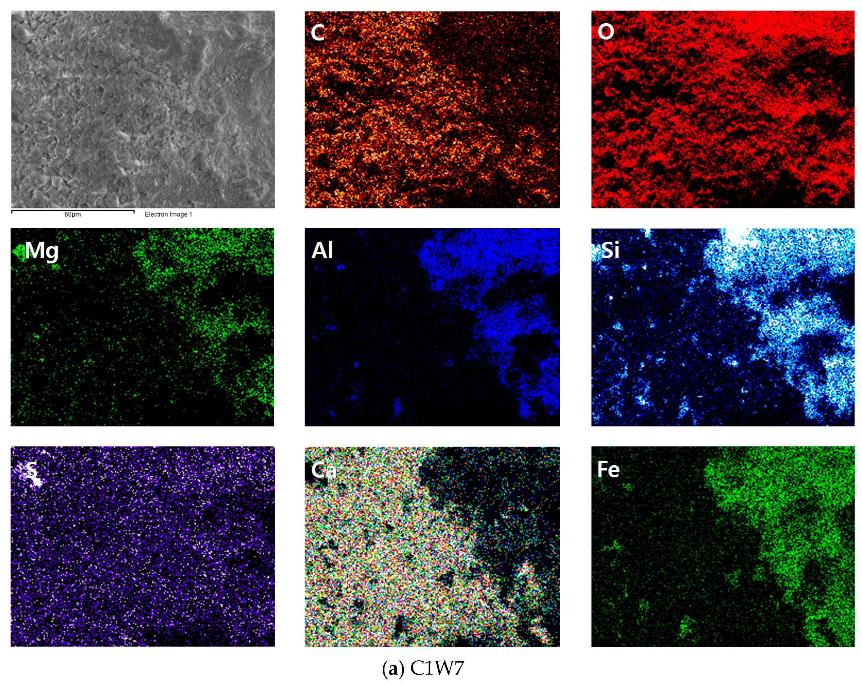
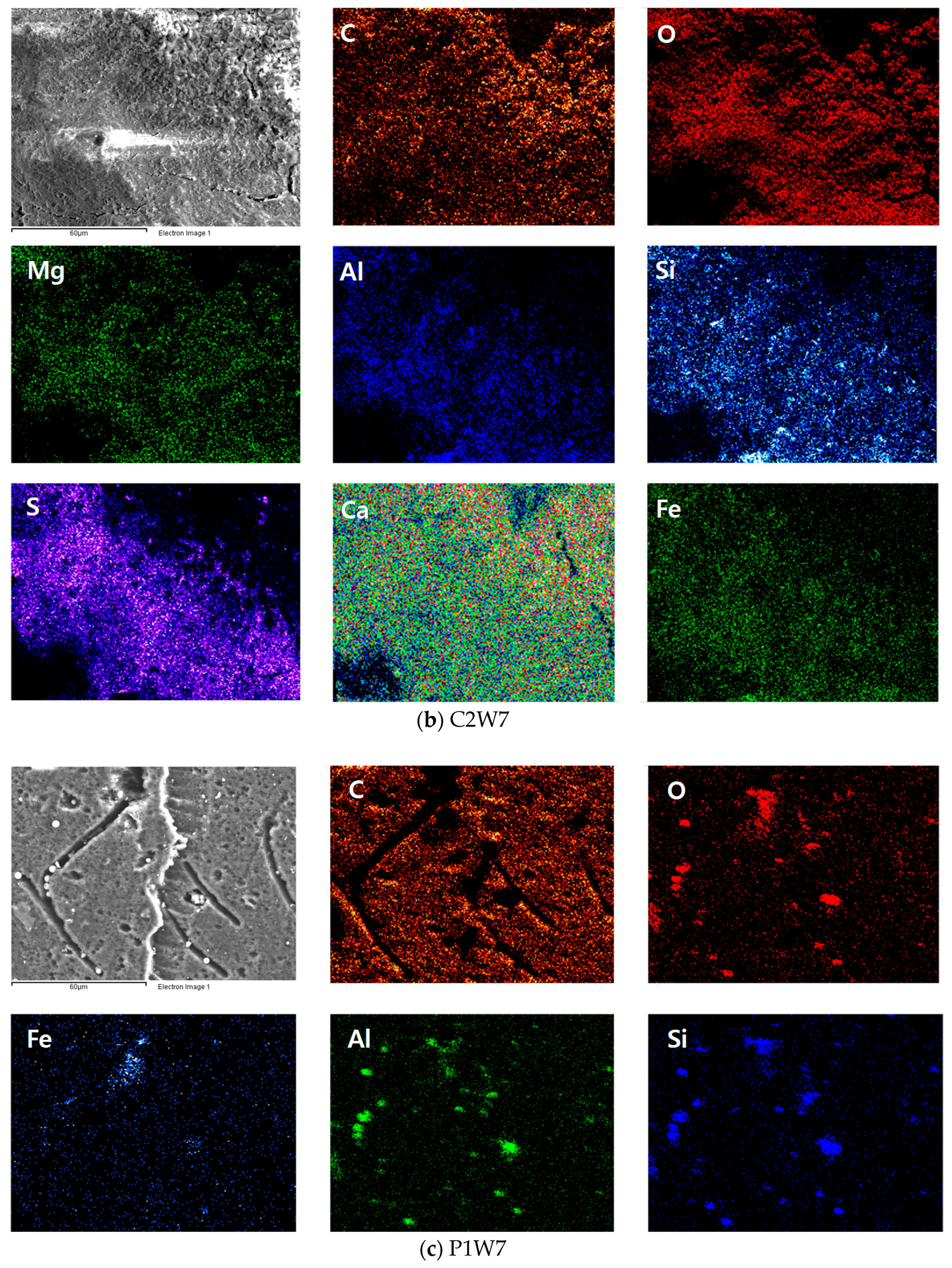
The precipitation of calcium carbonate on the surface of the CFBC bottom ash was confirmed using EDS mapping, as shown in Figure 5a,b. The EDS mapping results confirmed that the distribution of the carbon and calcium was similar, validating the presence of calcium carbonate in C1, C2 after the carbonation. In particular, the carbon distribution in the Si- and Fe-rich region, as shown in Figure 5a was low, indicating that calcium was the major facilitating component as CO2 sank into CFBC bottom ash. In the case of the EDS mapping results of P1W7, most of the surface of the sample was dominated by carbon elements, and unlike C1 and C2, Ca and O elements (carbonate) were not detected, thus supporting the finding that a large amount of unburned carbon was present in sample P1 but not in a carbonated form.
The surface area values calculated from the BET tests are shown in Table 5. It was found that the chemical products that were formed by carbonation on the surfaces of bottom ash samples C1 and C2 increased the surface area. The surface area of C1 increased by approximately three times the original value, while that of C2 increased by 58 times the original after carbonation. On the other hand, the change in surface area of P1 after carbonation was negligible, showing a similar value before and after carbonation. In general, the growth of carbonate crystal mainly occurred on the surface of CFBC bottom ash that was rich in calcium, due to the precipitation of calcite, leading to an increase in the surface area.
4. Discussion and Conclusions
The present study investigated carbonation sequestration of CO2 in CFBC bottom ash at low concentration of CO2, given the potential application to the post-combustion process in existing coal-fired power plants for CO2 capture. The result obtained herein may suggest a means of utilizing CFBC bottom ash, which currently has a low recycling rate, for the sequestration of CO2 generated from coal-fired power plants, providing an alternative option other than being reused as construction materials. Furthermore, the present study explored the mineral sequestration of CO2 in CFBC bottom ash by conducting a series of experimental tests that were designed to assess the CO2 uptake capacity of CFBC bottom ash. The main findings of this study can be summarized as follows.
The raw CFBC bottom ash was found to be rich in SiO2, Al2O3, Fe2O3, as well as CaO. The role of the CaO content in CFBC bottom ash was notably important for the CO2 uptake of the bottom ash. In particular, higher humidity conditions during the carbonation process were a critical factor that significantly enhanced the CO2 uptake in the CFBC bottom ash. In contrast, the bottom ash samples, which were carbonated in a dry condition (40% R.H.), had a relatively lower extent of carbonation (i.e., less CO2 uptake).
The SEM images of carbonated bottom ash samples suggest that the CO2 uptake mainly occurs on the calcium-rich surface of bottom ash particles via the precipitation of calcium carbonate. Moreover, this led to a significant change in the morphology of the bottom ash after wet carbonation, in particular, the surface area of the bottom ash with a high degree of carbonation had experienced an increase in the amount of calcite. In contrast, Si- and Fe-rich regions of bottom ash were generally less effective in terms of CO2 sequestration, that is, the morphology and surface area of the PC, with a relatively lower content of calcium, and hence a lower degree of carbonation, remained relatively unchanged after carbonation.
The XRD Rietveld refinement analysis results showed that not only CaO content, but other calcium-bearing phases (gehlenite, wollastonite, brownmillerite), in CFBC bottom ash were involved in the mineral carbonation reaction in a wet carbonation condition.
Both of the CFBC bottom ash samples stored carbon dioxide as calcite equally via wet carbonation. CFBC samples C1 and C2 stored 19.48 wt % and 14.60 wt %, that is, 0.195 and 0.146 tons of CO2, respectively, can presumably be stored per ton of each CFBC bottom ash. Meanwhile, while the PC sample did not undergo a carbonation reaction, hence it was not capable of storing carbon dioxide.
The results that were obtained in this study may provide a useful means of utilizing an industrial by-product as a CO2 sorbent and as a constituent material for concrete, since calcite, which is thermodynamically the most stable polymorph of calcium carbonate, precipitated by wet carbonation is a known cement admixture, which can be utilized as a number of construction materials.
Acknowledgments
This study was supported by a National Research Foundation of Korea (NRF) grant funded by the Korean government (Ministry of Science, ICT & Future Planning) (2015R1A2A1A10055694), and by the Saudi Aramco—KAIST CO2 Management Center to whom the authors are grateful. The authors would like to thank Sol-Moi Park at KAIST for his help in this study.
Author Contributions
H.J.K. designed the experiments, analyzed data and wrote the paper under supervision of H.K.L.
Conflicts of Interest
The authors declare no conflicts of interest.
References
- Bruhn, T.; Naims, H.; Olfe-Kräutlein, B. Separating the debate on CO2 utilisation from carbon capture and storage. Environ. Sci. Policy 2016, 60, 38–43. [Google Scholar] [CrossRef]
- Cox, P.M.; Betts, R.A.; Jones, C.D.; Spall, S.A.; Totterdell, I.J. Acceleration of global warming due to carbon-cycle feedbacks in a coupled climate model. Nature 2000, 408, 184–187. [Google Scholar] [CrossRef] [PubMed]
- Energy Information Administration. Monthly Energy Review; Energy Information Administration: Washington, DC, USA, 2014.
- Haynes, R. Reclamation and revegetation of fly ash disposal sites—Challenges and research needs. J. Environ. Manag. 2009, 90, 43–53. [Google Scholar] [CrossRef] [PubMed]
- U.S. Energy Infromation Administration. International Energy Outlook 2016; U.S. Energy Infromation Administration: Washington, DC, USA, 2016.
- Anthony, E.; Bulewicz, E.M.; Dudek, K.; Kozak, A. The long term behaviour of cfbc ash—Water systems. Waste Manag. 2002, 22, 99–111. [Google Scholar] [CrossRef]
- Selcuk, N.; Ozkan, M. Simulation of circulating fluidized bed combustors firing indigenous lignite. Int. J. Therm. Sci. 2011, 50, 1109–1115. [Google Scholar] [CrossRef]
- Selvakumaran, P.; Lawerence, A.; Lakshminarasimhan, M.; Bakthavatsalam, A. Mineralogical influence of mining intrusions in CFB combustion of indian lignite. Int. J. Energy Environ. Eng. 2013, 4, 34. [Google Scholar]
- Innovation for Cool Earth Forum, Global Roadmap for Implementing CO2 Utilization. 2016. Available online: www.globalco2initiative.org/webinar (accessed on 18 April 2017).
- Chi, M.; Huang, R. Effect of circulating fluidized bed combustion ash on the properties of roller compacted concrete. Cem. Concr. Compos. 2014, 45, 148–156. [Google Scholar] [CrossRef]
- Havlica, J.; Brandstetr, J.; Odler, I. Possibilities of utilizing solid residues from pressured fluidized bed coal combustion (PSBC) for the production of blended cements. Cem. Concr. Res. 1998, 28, 299–307. [Google Scholar] [CrossRef]
- Zhang, W.; Choi, H.; Sagawa, T.; Hama, Y. Compressive strength development and durability of an environmental load-reduction material manufactured using circulating fluidized bed ash and blast-furnace slag. Constr. Build. Mater. 2017, 146, 102–113. [Google Scholar] [CrossRef]
- Bertos, M.F.; Simons, S.; Hills, C.; Carey, P. A review of accelerated carbonation technology in the treatment of cement-based materials and sequestration of CO2. J. Hazard. Mater. 2004, 112, 193–205. [Google Scholar]
- Renforth, P.; Washbourne, C.-L.; Taylder, J.; Manning, D. Silicate Production and Availability for Mineral Carbonation; ACS Publications: Washington, DC, USA, 2011. [Google Scholar]
- Ukwattage, N.; Ranjith, P.; Yellishetty, M.; Bui, H.; Xu, T. A laboratory-scale study of the aqueous mineral carbonation of coal fly ash for CO2 sequestration. J. Clean. Prod. 2015, 103, 665–674. [Google Scholar] [CrossRef]
- Wang, C.; Jia, L.; Tan, Y.; Anthony, E.J. Carbonation of fly ash in oxy-fuel CFB combustion. Fuel 2008, 87, 1108–1114. [Google Scholar] [CrossRef]
- Wee, J.-H. A review on carbon dioxide capture and storage technology using coal fly ash. Appl. Energy 2013, 106, 143–151. [Google Scholar] [CrossRef]
- Montes-Hernandez, G.; Perez-Lopez, R.; Renard, F.; Nieto, J.; Charlet, L. Mineral sequestration of CO2 by aqueous carbonation of coal combustion fly-ash. J. Hazard. Mater. 2009, 161, 1347–1354. [Google Scholar] [CrossRef] [PubMed] [Green Version]
- Soong, Y.; Fauth, D.; Howard, B.; Jones, J.; Harrison, D.; Goodman, A.; Gray, M.; Frommell, E. CO2 sequestration with brine solution and fly ashes. Energy Convers. Manag. 2006, 47, 1676–1685. [Google Scholar] [CrossRef]
- Salvador, C.; Lu, D.; Anthony, E.; Abanades, J. Enhancement of CaO for CO2 capture in an FBC environment. Chem. Eng. J. 2003, 96, 187–195. [Google Scholar] [CrossRef]
- Cebrucean, D.; Cebrucean, V.; Ionel, I. CO2 capture and storage from fossil fuel power plants. Energy Procedia 2014, 63, 18–26. [Google Scholar] [CrossRef]
- Olajire, A.A. CO2 capture and separation technologies for end-of-pipe applications—A review. Energy 2010, 35, 2610–2628. [Google Scholar] [CrossRef]
- Abanades, J.C.; Alvarez, D. Conversion limits in the reaction of CO2 with lime. Energy Fuels 2003, 17, 308–315. [Google Scholar] [CrossRef]
- Ozcan, D.C.; Macchi, A.; Lu, D.Y.; Kierzkowska, A.M.; Ahn, H.; Müller, C.R.; Brandani, S. Ca–Cu looping process for CO2 capture from a power plant and its comparison with ca-looping, oxy-combustion and amine-based CO2 capture processes. Int. J. Greenh. Gas Control 2015, 43, 198–212. [Google Scholar] [CrossRef]
- Adanez, J.; Abad, A.; Garcia-Labiano, F.; Gayan, P.; Luis, F. Progress in chemical-looping combustion and reforming technologies. Prog. Energy Combust. Sci. 2012, 38, 215–282. [Google Scholar] [CrossRef] [Green Version]
- Ridha, F.N.; Manovic, V.; Macchi, A.; Anthony, E.J. CO2 capture at ambient temperature in a fixed bed with CaO-based sorbents. Appl. Energy 2015, 140, 297–303. [Google Scholar] [CrossRef]
- Burnard, K.; Bhattacharya, S. Power Generation from Coal; IEA Information Paper; IEA: Paris, France, 2011; pp. 1–49. [Google Scholar]
- World Energy Council. World Energy Resources; World Energy Council: London, UK, 2016; pp. 1–73. [Google Scholar]
- Leung, D.Y.; Caramanna, G.; Maroto-Valer, M.M. An overview of current status of carbon dioxide capture and storage technologies. Renew. Sustain. Energy Rev. 2014, 39, 426–443. [Google Scholar] [CrossRef] [Green Version]
- Loo, L.; Maaten, B.; Konist, A.; Siirde, A.; Neshumayev, D.; Pihu, T. Carbon dioxide emission factors for oxy-fuel CFBC and aqueous carbonation of the Ca-rich oil shale ash. Energy Procedia 2017, 128, 144–149. [Google Scholar] [CrossRef]
- Rao, A.; Anthony, E.; Jia, L.; Macchi, A. Carbonation of FBC ash by sonochemical treatment. Fuel 2007, 86, 2603–2615. [Google Scholar] [CrossRef]
- Uibu, M.; Uus, M.; Kuusik, R. CO2 mineral sequestration in oil-shale wastes from estonian power production. J. Environ. Manag. 2009, 90, 1253–1260. [Google Scholar] [CrossRef] [PubMed]
- Chindaprasirt, P.; Rattanasak, U. Utilization of blended fluidized bed combustion (FBC) ash and pulverized coal combustion (PCC) fly ash in geopolymer. Waste Manag. 2010, 30, 667–672. [Google Scholar] [CrossRef] [PubMed]
- ASTM International Voluntary Organization C114–13. Standard Test Methods for Chemical Analysis of Hydraulic Cement; ASTM International Voluntary Organization: West Conshohocken, PA, USA, 2013. [Google Scholar]
- Huijgen, W.J.; Witkamp, G.-J.; Comans, R.N. Mineral CO2 sequestration by steel slag carbonation. Environ. Sci. Technol. 2005, 39, 9676–9682. [Google Scholar] [CrossRef] [PubMed]
- Jens, G.; Nasdala, L.; Kleeberg, R.; Wenzel, M. Occurrence and distribution of “moganite” in agate/chalcedony: A combined micro Raman, Rietveld, and cathodoluminescence study. Contrib. Mineral. Petrol. 1998, 133, 96–105. [Google Scholar]
- Ahmaruzzaman, M. A review on the utilization of fly ash. Prog. Energy Combust. Sci. 2010, 36, 327–363. [Google Scholar] [CrossRef]
- Hoschek, G. Gehlenite stability in the system CaO-Al2O3-SiO2-H2O-CO2. Contrib. Mineral. Petrol. 1974, 47, 245–254. [Google Scholar] [CrossRef]
- Singh, M.; Garg, M. Activation of gypsum anhydrite-slag mixtures. Cem. Concr. Res. 1995, 25, 332–338. [Google Scholar] [CrossRef]
Figure 1.
Carbonation conditions and nomenclatures of the samples.

Figure 2.
The amount of CO2 sequestrated in bottom ash samples, quantified using TIC analysis.
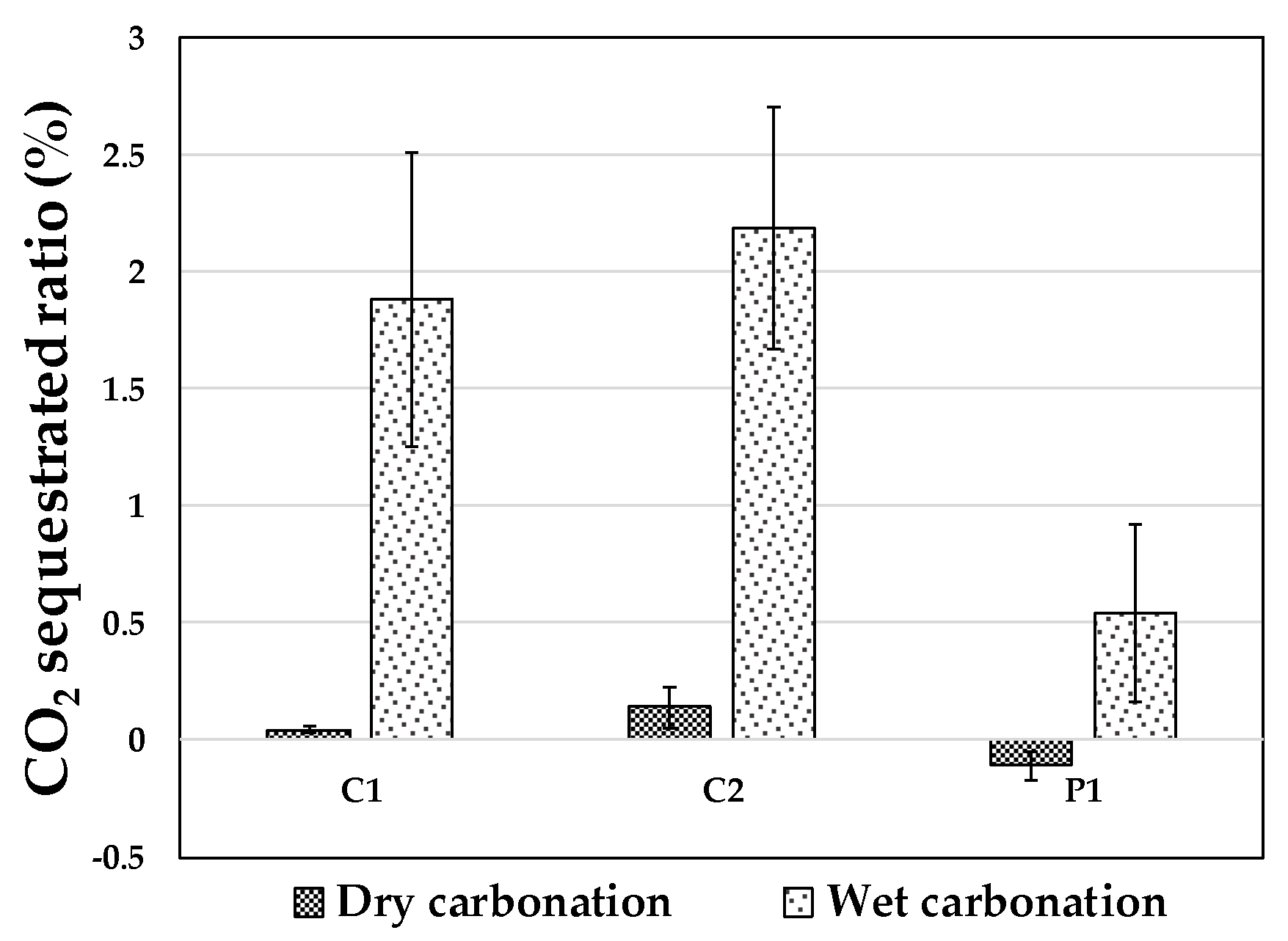
Figure 3.
XRD pattern of carbonated bottom ash (a) C1; (b) C2; and (c) P1.

Figure 4.
Scanning electron microscopy (SEM) images of raw bottom ashes, pre-carbonation and wet carbonation: (a) C1 (low magnification 1000×); (b) C1W7 (low magnification 1000×); (c) C1W7 (high magnification 6000×); (d) C2 (low magnification 1000×); (e) C2W7 (low magnification 1000×); (f) C2W7 (high magnification 6000×); (g) P1 (low magnification 1000×); (h) PW7 (low magnification 1000×); and (i) P1W7 (high magnification 6000×).

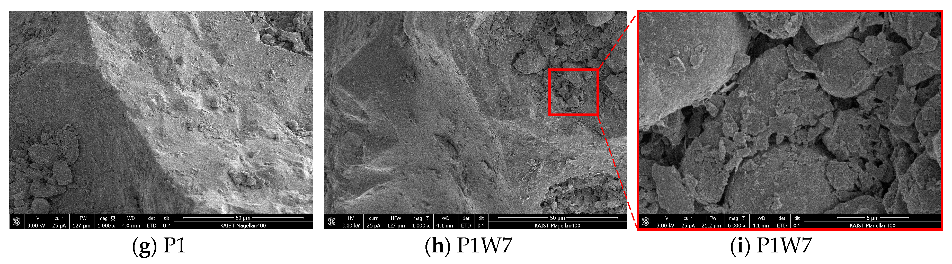
Figure 5.
EDS elemental mapping images of (a) C1W7; (b) C2W7; and (c) P1W7.


Table 1.
Chemical compositions of the circulating fluidized bed combustion (CFBC) bottom ash and PC bottom ash samples.
Table 1.
Chemical compositions of the circulating fluidized bed combustion (CFBC) bottom ash and PC bottom ash samples.
| Oxide Contents (wt %) | C1 | C2 | P1 |
|---|---|---|---|
| CaO | 47.6 | 52.7 | 2.1 |
| Free CaO contents (%) | 0.61 | 4.94 | 0.04 |
| SiO2 | 7.4 | 11.3 | 27.0 |
| Al2O3 | 3.5 | 7.0 | 16.0 |
| Fe2O3 | 19.6 | 4.7 | 21.7 |
| MgO | 3.0 | 1.3 | 4.0 |
| Na2O | 16.0 | - | 17.0 |
| K2O | 0.5 | 0.4 | 6.1 |
| SO3 | 0.9 | 20.5 | 0.7 |
| TiO2 | 0.6 | 0.5 | 4.6 |
| MnO | 0.1 | 0.1 | 0.2 |
| P2O5 | - | 0.9 | 0.1 |
Table 2.
Total inorganic carbon (TIC) results of bottom ash, expressed as an elemental percentage. Standard deviation is shown in a parenthesis.
Table 2.
Total inorganic carbon (TIC) results of bottom ash, expressed as an elemental percentage. Standard deviation is shown in a parenthesis.
| Sample | Pre-Carbonation | Dry Carbonation | Wet Carbonation |
|---|---|---|---|
| C1 | 0.187% (0.05) | 0.231% (0.01) | 2.067% (0.16) |
| C2 | 0.197% (0.04) | 2.385% (0.14) | 2.385% (0.12) |
| P1 | 9.899% (4.34) | 9.792% (1.18) | 10.439% (2.67) |
Table 3.
XRD Rietveld refinement analysis of carbonated bottom ash.
| Mineral | C1 | C1D7 | C1W7 | C2 | C2D7 | C2W7 | P1 | P1D7 | P1W7 |
|---|---|---|---|---|---|---|---|---|---|
| Calcite (CaCO3) | 8.7 | 25.4 | 53.0 | 0.5 | 2.1 | 33.7 | 0.3 | 0.2 | |
| Quartz (SiO2) | 31.6 | 35.4 | 18.9 | 10.3 | 19.6 | 2.2 | 16.3 | 15.2 | 19.8 |
| Lime (CaO) | 0.7 | 1.0 | 0.4 | 14.6 | 17.0 | 0.1 | - | - | - |
| Brownmillerite (Ca2(Al,Fe)2O5) | 13.7 | 16.8 | 7.3 | - | - | - | - | - | - |
| Gehlenite (Ca2Al(AlSiO7)) | 18.3 | 13.4 | - | 24.8 | - | - | - | - | - |
| Mullite (Al6Si2O13) | - | - | - | - | - | - | 81.3 | 79.5 | 80.0 |
| Anhydrite (CaSO4) | - | - | - | 47.9 | 59.3 | 32.6 | - | - | - |
| Corundum (Al2O3) | - | - | - | - | - | - | 2.1 | 5.3 | - |
| Nepheline ((Na,K)AlSiO4) | 4.9 | 3.2 | - | - | - | - | - | - | - |
| Wollastonite (CaSiO3) | 4.6 | 4.7 | - | - | - | - | - | - | - |
| Magnesium Oxide (MgO) | - | - | - | 1.2 | 0.8 | - | - | - | - |
| Magnesite (MgCO3) | 17.3 | - | - | - | - | - | - | - | - |
| Cristobalite (SiO2) | 0.1 | - | - | - | - | - | - | - | - |
| Calcium Titanate (CaTiO3) | - | - | 0.8 | - | - | - | - | - | - |
| Anorthite sodian (CaAl2Si2O8) | - | - | 19.6 | - | - | - | - | - | - |
| Gypsum (CaSO4∙2H2O) | - | - | - | - | - | 29.4 | - | - | - |
| Portlandite Ca(OH)2 | - | - | - | - | 1.0 | - | - | - | - |
| Rutile (TiO2) | - | - | - | 0.7 | - | - | - | - | - |
| Ettringite (CaO)6(Al2O3)(SO3)3·32H2O | - | - | - | - | - | 2.1 | - | - | - |
Table 4.
Calculated amounts of CO2 sequestrated by using XRD Rietveld refinement analysis (wt %).
| Sample | Dry Carbonation | Wet Carbonation |
|---|---|---|
| C1 | 7.34 | 19.48 |
| C2 | 0.70 | 14.60 |
| P1 | - | - |
Table 5.
The BET surface area of CFBC bottom ash and pulverized coal-fired (PC) bottom ash samples, pre-carbonation and post-carbonation (m2/g).
Table 5.
The BET surface area of CFBC bottom ash and pulverized coal-fired (PC) bottom ash samples, pre-carbonation and post-carbonation (m2/g).
| Sample | Pre-Carbonation | Post-Carbonation |
|---|---|---|
| C1 | 0.8887 | 3.2826 |
| C2 | 0.3208 | 18.6235 |
| P1 | 1.5973 | 1.5511 |
© 2017 by the authors. Licensee MDPI, Basel, Switzerland. This article is an open access article distributed under the terms and conditions of the Creative Commons Attribution (CC BY) license (http://creativecommons.org/licenses/by/4.0/).
Share and Cite
MDPI and ACS Style
Kim, H.-J.; Lee, H.-K. Mineral Sequestration of Carbon Dioxide in Circulating Fluidized Bed Combustion Boiler Bottom Ash. Minerals 2017, 7, 237. https://doi.org/10.3390/min7120237
AMA Style
Kim H-J, Lee H-K. Mineral Sequestration of Carbon Dioxide in Circulating Fluidized Bed Combustion Boiler Bottom Ash. Minerals. 2017; 7(12):237. https://doi.org/10.3390/min7120237
Chicago/Turabian StyleKim, Hee-Jeong, and Haeng-Ki Lee. 2017. "Mineral Sequestration of Carbon Dioxide in Circulating Fluidized Bed Combustion Boiler Bottom Ash" Minerals 7, no. 12: 237. https://doi.org/10.3390/min7120237
Note that from the first issue of 2016, this journal uses article numbers instead of page numbers. See further details here.