
An Innovative Support Structure for Gob-Side Entry Retention in Steep Coal Seam Mining

State Key Laboratory of Mining Disaster Prevention and Control Co-founded by Shandong Province and the Ministry of Science and Technology, Shandong University of Science and Technology, Qingdao 266590, China
*
Authors to whom correspondence should be addressed.
†
These authors contributed equally to this work.
Minerals 2017, 7(5), 75; https://doi.org/10.3390/min7050075
Submission received: 30 March 2017
/
Revised: 3 May 2017
/
Accepted: 8 May 2017
/
Published: 11 May 2017
Abstract
:This study considered longwall working face No. 41101—located in a steeply inclined coal seam at the Awuzisu coal mine in Xinjiang, China—as an example in which macroscopic shear cracks had occurred in the cement-based filling body of the gob-side entry retention structure. A mechanical model of the support structure for the gob-side entry retention was first established. Then, field observations and laboratory tests were used to obtain the force exerted by the coal wall on the main roof, the relationship between the axial bearing capacity and compression ratio of the rubble inside the gob, the supporting force exerted by the rubble and filling body, and the thrust of the rubble on the filling body. The shear stress experienced by the roadside filling body of the gob-side entry retention in working face No. 41101 was calculated to be 15.89 MPa. To meet the needs of roadside support, an innovative roadside backfill–truss support structure was adopted, with a 60° angle of inclination used for the anchor bolts of the gob-side entry retention structure. In this way, the ultimate shear strength was improved by 107.54% in comparison with the cement-based filling body.
1. Introduction
Over the past few decades, the gob-side entry retention technique has been widely used in China, Poland, and Ukraine [1,2,3,4,5]. A gob-side entry retention structure is a type of roadway without pillars, in which the former entry roadway is retained for transportation (or as a return air gate road) during the mining of the next panel by constructing an artificial wall along the gob-side, lagging behind the coal face being excavated [6,7]. As a major technique for realizing pillar-less mining in coal mines, it can improve the recovery rate of coal resources and prolong the mine’s service life. It presents a superior method for preventing major disasters in mines such as rock bursts and gas outbursts [8].
At present, gob-side entry retention has been successfully applied to the working faces of approximately horizontal, and gently inclined, coal seams [9,10,11,12,13]. However, it is still difficult to use gob-side entry retention for the working faces of steeply inclined coal seams because of complications. For example, in a steep coal seam, the rock beams of the lateral main roof (or the immediate roof strata) are likely to move along the inclined direction of the bedding [14,15,16]. Under such circumstances, the roadside filling body (an artificial wall created by pouring high-water quick-setting materials) is expected to bear a large shear force, which can lead to the overall slipping and bulging of the filling body [17,18,19]. Therefore, establishing a mechanical model for the support of the gob-side entry retention in steeply inclined coal seams and improving the anti-shear characteristics of the roadside filling body are crucial steps. This can not only provide reassurance when realizing gob-side entry retention in steep coal seams, but will also enrich and develop the theory and technique of gob-side entry retention.
A mechanical model for the support of the gob-side entry retention in steep coal seams was established based on the geological and mining conditions of the fully mechanized coalface in the steeply inclined coal seam at the Awuzisu coal mine in Xinjiang, China. Then, this model was used to obtain the shear stresses on the roadside filling body after the motion of the roof had stabilized, and a suitable roadside backfill–truss support structure was proposed. Second, by performing laboratory tests on similar materials, we acquired the optimal installation angle for the anchor bolts used in the roadside backfill–truss support structure. Afterwards, the shear strength of the roadside backfill–truss support body was calculated through field testing. Finally, the system’s suitability was verified on site.
2. Geological and Mining Conditions at Awuzisu Coal Mine in Xinjiang, China
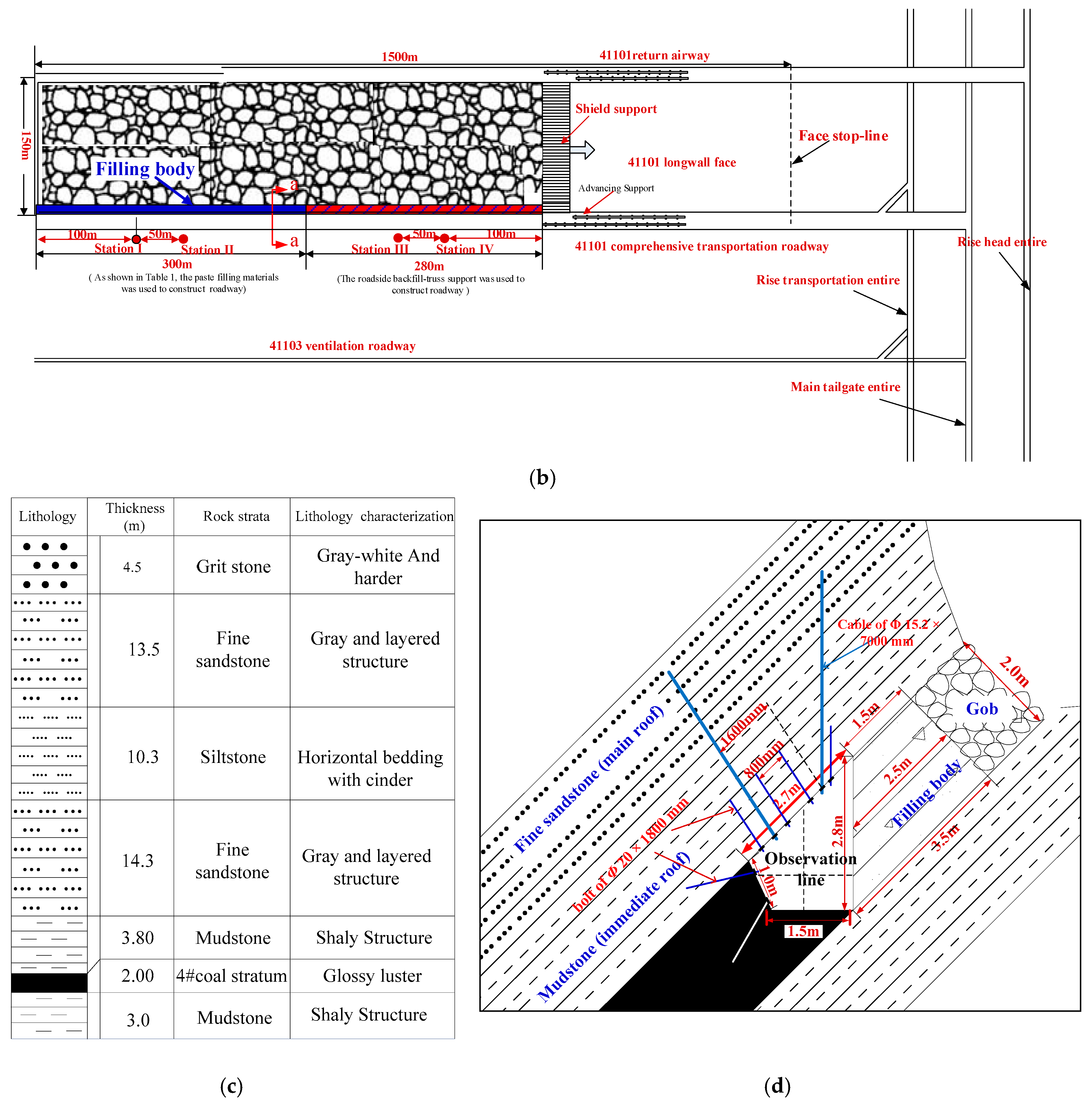
The Awuzisu coal mine is in the southeastern margin of the Junggar Basin. Inclined shaft (including the main inclined shafts, auxiliary inclined shafts, and air shafts) development was adopted in the coal field, as shown in Figure 1a,b. The mineable coal seams include #4, #5, and #6, from which coal seam #4 is currently being mined. With an average burial depth of 400 m, the occurrence of coal seam #4 is stable. In addition, the thickness of the coal seam ranges from 1.8 m to 2.2 m, with the average thickness being 2 m. The dip angle of the coal seam is 43° to 47°, with the average angle of dip being 45°. The immediate roof is composed of mudstone, and is 3.8 m thick, with a uniaxial compressive strength (USC) and density of 23 MPa and 2435 kg/m3, respectively. The 24.6 m thick main roof is composed of siltstone and fine sandstone. It has a density of 2784 kg/m3 and USC of 55 MPa (on average). Figure 1c shows the lithological profile of the roof strata in the coal seam.
As the first working face in the first mining area of coal seam #4, working face No. 41101 uses fully mechanized coal mining, with strike and inclination lengths of 1500 m and 150 m, respectively. Working face No. 41101 is supported by a ZZ6500/16/25 standing shield hydraulic support with a rated working resistance of 6500 kN and setting load of 5232 kN. In addition, a MG450/1020-GWD electrical haulage shearer running on variable frequency AC is used to cut the coal. With a rated voltage of 3300 V and frequency of 50 Hz, the shearer can work at a web depth of 0.8 m. The shearer has an installed power rating of not less than 1006 kW, a haulage speed of over 4.5 m/min, and a roller with a diameter of 2.5 m. The working face is mined at an average advancement rate of 8 m per day.
The main transportation roadway of working face No. 41101 is excavated along the roof in an irregular section, as illustrated in Figure 1d. The roadway is jointly supported by anchor bolts (anchor cables), a steel strip, and metal nets. Threaded steel resin bolts with a diameter and length of 20 mm and 1800 mm, respectively, and containing no longitudinal reinforcement, are applied to the roof. The bolts, each of which is fixed using the CK2335 resin anchoring agent, are arranged with row and column lengths of 800 mm × 800 mm. The anchor cables, which are 15.2 mm in diameter and 7000 mm in length, are set at intervals of 1600 mm in both the rows and columns. In addition, three CK2335 resin anchoring agents are installed in each hole for the purpose of anchoring the ends. Threaded steel resin bolts without longitudinal reinforcement are used on the walls of the roadway. The bolts, with a diameter and length of 20 mm and 1800 mm, respectively, are fixed at 800 mm intervals in both the rows and columns. In addition, the metal net is made of reinforced steel with a diameter of 6.5 mm, and the size of the grid is 100 mm × 100 mm. The length, width, and thickness of the steel strips are 1000 mm, 80 mm, and 5 mm, respectively.
Frames were set into the margin of the gob, with the space being filled with paste filling materials at every 3.2 m of mining length to preserve the No. 41101 main transportation roadway as the return airway of the working face. The cement-based filling materials were prepared with the proportions listed in Table 1. The relationships between the strength and curing time of the cement-based filling body are shown in Figure 2. Initially, the widths of the upper and lower surfaces, as well as the middle part of the filling body, were designed to be 1.5 m, 3.5 m, and 2.5 m, respectively. In the field investigation, a filling body that was 300 m long was prepared.
Two observation stations (I and II) were established in the roadway, as shown in Figure 1b. A laser measuring instrument was used to measure the convergence between the roof and the floor, as well as that between the middle parts of the two walls of the roadway using the crossing method, as shown in Figure 1d. In Figure 3, the results indicate that the roadway roof significantly sagged when the filling body was 40–45 m behind the working face, i.e., five to six days after being constructed. Moreover, macroscopic shearing cracks occurred on the roadside filling body, and the roadway needed to be reinforced many times to maintain the stability of the surrounding rocks.
3. Shear Strength of Roadside Filling Body of Gob-Side Entry Retention Structure in Steep Coal Seam
3.1. Mechanical Model of Gob-Side Entry Retention Work in Steep Coal Seam
After a steep coal seam is exploited, the motion of the lateral roof of the working face can be separated into two stages [20,21]. During stage I, the immediate roof strata rotationally subside and collapse into the gob. This collapsed rubble slips downward along the inclined direction of the coal seam under the effect of gravity, and gradually forms heaps at the side of the roadside filling body of the gob-side entry retention work. In stage II, when the hanging length of the rock beam of the lateral main roof reaches its limit, the rock beam is fractured in the coal wall and rotationally subsides until it contacts, and compacts, the rubble inside the gob, as shown in Figure 4.
In contrast to approximately horizontal and gently inclined coal seams, the roof strata of the working face of a steeply inclined coal seam tend to move downward along the inclined direction. Meanwhile, pushed by the rubble inside the gob, the roadside filling body of the gob-side entry retention bears a large tangential stress, which makes it easier for the filling body to be shear-fractured. Assume that the dip angle of the coal seam is α, and the rock beam A of the lateral main roof subsides rotationally around point D of the fracture line and is pushed by rock beam B at point E. The rotation angle of rock beam A is θ, and there is no separation between the main roof and the immediate roof. The self-weight forces of the immediate roof and rock beam A act on the rubble inside the gob, the filling body, and the coal wall. The mechanical models of the roof and filling body of the gob-side entry retention in a steeply inclined coal seam can be established in this way, as shown in Figure 4 and Figure 5, respectively.
3.1.1. Supporting Force of Coal Wall
If we assume that the supporting force of the coal wall on the roof strata is Fc (Figure 4), then its component in the y-direction, Fcy, is linearly distributed and varies from q1y to q2y, which can be obtained using a borehole stress meter. Meanwhile, its component in the x-direction, Fcx, is also linearly distributed and ranges from q1x and q2x. Then, the forces acting from the coal wall on the roof strata in the x- and y-directions, Fcx and Fcy, respectively, can be calculated using Equation (1):
where ; ; α is the dip angle of the coal seam (°); θ is the rotation angle of rock beam A in the main roof (°); L2 is the broken length of rock beam A (m); is the deflection (subsidence) of rock beam A (m); h is the mining height of the working face (m); mz and L0 are the thicknesses of the immediate roof and the length from the lateral fracture line to the coal wall, respectively (m); and KA is the bulking coefficient of the gangue, and its value is taken from the relevant literature [22].
3.1.2. Supporting Force from Rubble inside Gob
The components of the supporting force of the rubble, Fg, in the x- and y-directions are Fgx and Fgy, respectively, where the component in the x-direction, Fgy, is related to the contacting length of rock beam A with the rubble, and the final compression of the rubble. In a steeply inclined coal seam, because the rubble inside the gob mainly accumulates around the roadside filling body, rock beam A can make sufficient contact with it. The length L3 of the rubble in contact can be calculated using Equation (2):
where L1 is the strike length from the lateral fracture line to the end of the immediate roof in meters.
Because rock beam A makes sufficient contact with the rubble inside the gob, the supporting force of the rubble on rock beam A can be assumed to be a uniform load qgy. In accordance with a related study [23], it can be found that qgy is exponentially related to the compression ratio of the rubble, as follows:
where a, b, and c are constants obtained from an experiment, is the compression ratio of the rubble, , S is the final compression of the rubble inside the gob, and S = (KA − 1) Mz. Therefore, the supporting forces from the rubble inside the gob to rock beam A, in the x- and y-directions Fgx and Fgy, respectively, are represented as follows:
3.1.3. Supporting Force from Filling Body
The equation for the mechanical equilibrium in the x- and y-directions is established according to the model shown in Figure 4. Based on this equation, the forces acting between the roadside filling body and roof strata, Fby, and Fbx, can be calculated as follows:
where γz and γE are the bulk densities of the immediate roof and main roof (kN/m3), respectively; mE is the thickness of the rock beam of the main roof (m); FDy and FDx are the forces caused by rock beam A at articulation points D; and FEx and FEy are the forces caused by rock beam B at articulation point E. According to the result of Tan et al. [2,7], and .
3.1.4. Shear Stress on Roadside Filling Body
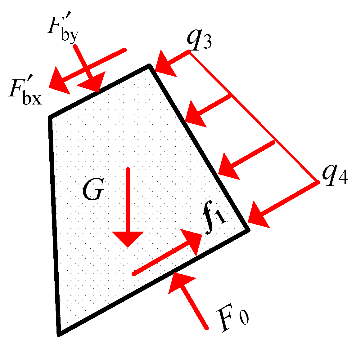
In the mechanical model of the roadside filling body shown in Figure 5, and represent the forces acting between the roof strata and filling body in the y- and x-directions, respectively. They are the force and reaction force to Fby and Fbx, respectively. F0 refers to the supporting force from the floor to the filling body, while f1 is the friction force between the filling body and floor strata. Suppose that the thrust caused by the rubble inside the gob on the filling body is linearly distributed, varies from q3 to q4, and can be measured by the in situ stress sensor. By establishing the equation of mechanical equilibrium in the x-direction, we can obtain the shear stress τ on the roadside filling body as follows:
where , μ1 is the friction coefficient between the filling body and floor strata, G is the self-weight of the filling body (kN/m), d is the equivalent width of the roadside filling body (m), and hc is the vertical height of the filling body in the y-direction (m).
3.2. Shear Strength of Filling Body
3.2.1. Supporting Force from Coal Wall
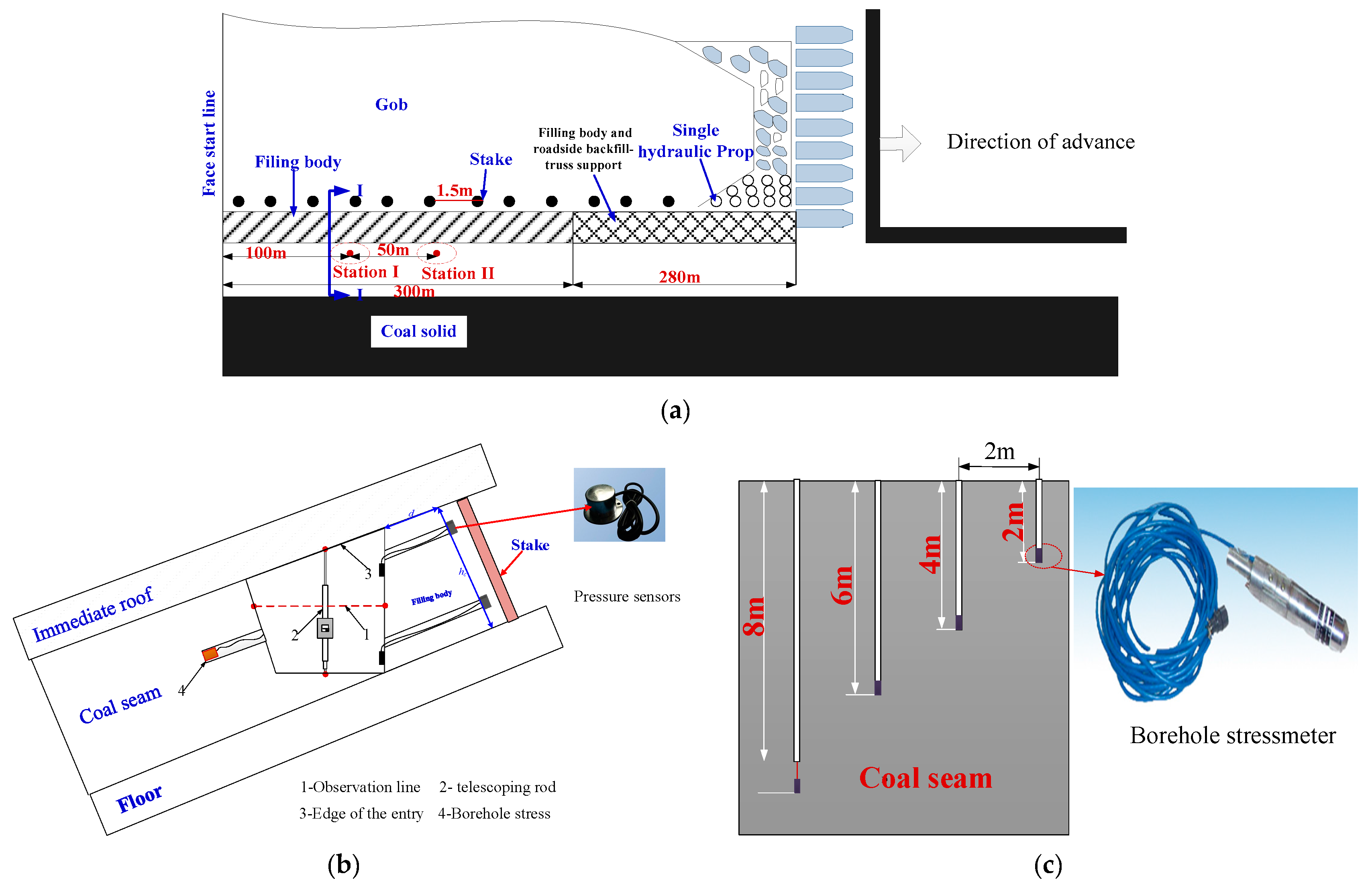
Two observation stations were established at 100 m (station I) and 150 m (station II) from the open-off cut in the roadway, as shown in Figure 6a. Four borehole stress meters were fixed in the coal wall of the observation stations at depths of 2 m, 4 m, 6 m, and 8 m, respectively. These borehole stress meters were set at intervals of 2 m to monitor the changes in coal pressure over a 30 day period, as shown in Figure 6b,c. The changes in the pressure on the lateral coal walls in the roadway after the working face was advanced were found by averaging the data obtained using the borehole stress meters at the same depth (Figure 7). According to another study [2,24], the fracture line of the main roof was at the same location as the peak abutment pressure. Therefore, the lateral peak abutment pressure of the working face was situated approximately 4 m inside the coal wall of the roadway, namely, at L0 = 4 m. By solving for the average values of data acquired from the two observation stations, the vertical pressures at the fracture line of the main roof near the roadway surface, q1y and q2y, were calculated to be 0.5 MPa and 1.5 MPa, respectively.
Because the mining height of working face No. 41101 is 2 m (on average), the deflection (subsidence) of rock beam A of the main roof was 1.126 m. Thus, a value of 3° could finally be obtained for the rotation angle θ of rock beam A, and the dip angle of the coal seam, α, was 45°. According to Equation (1), the forces acting from the coal wall to the main roof strata, Fcx and Fcy, were 4.44 × 10³ kN and 4.00 × 10³ kN, respectively.
3.2.2. Supporting Force of Rubble inside Gob
1. experiment on load-carrying properties of rubble inside gob
To explore the load-carrying properties of the rubble inside the gob, the author designed loading molds, which were made of Q350 stainless steel plates measuring 300 mm × 300 mm × 300 mm. The rubble, randomly collected on site, was placed into the molds, with fixed lateral constraints. Thus, the load-carrying properties of the obtained rubble were similar to those under actual conditions. Figure 8 shows the device and molds used in the loading test. The loading test was performed on a WE-1000C hydraulic testing machine under multi-stage loading. Meanwhile, by measuring the height of the rubble at each load increment using a measuring tape with a precision of 0.01 mm, the relationship between the bearing capacity and compression ratio of the gangue was acquired, as shown in Figure 9. The results of this experiment suggested that the bearing capacity of the rubble in the gob grew exponentially with an increase in the compression ratio of the rubble. After fitting Equation (3), the relation between the axial bearing capacity and compression ratio of the gangue can be expressed as follows:
The supporting force from the rubble in the gob to rock beam A of the main roof in the y-direction is as follows:
2. supporting force from rubble in gob
A laser measuring instrument was installed at the end of the support of the working face to measure the fracture span of the immediate roof in the gob. This field test revealed that the immediate roof collapsed along the outside of the filling body. The fracture span L2 of the rock beam of the lateral main roof was approximately equal to the periodic weighted length of the working face [24,25], which was 21.5 m. The length from the lateral fracture line to the end of the immediate roof, L1 was 8.5 m. According to Equation (2), the length of rock beam A of the main roof that was in contact with the rubble, L3, was 13 m. In addition, the immediate roof was 3.8 m thick, and the bulking coefficient KA of the rubble inside the gob was 1.3. The final compression S of the rubble inside the gob was 1.14, with a corresponding compression ratio of 0.19. Therefore, based on Equations (4) and (9), the supporting forces from the rubble inside the gob to the rock beam A, Fgx and Fgy, can be calculated to be 1.65 × 10³ kN/m and 1.49 × 10³ kN/m, respectively.
3.2.3. Supporting Force from Filling Body
Working face No. 41101 is 2 m in height (on average). The deflection subsidence of rock beam A of the main roof was 1.126 m. Based on these parameters, the rotation angle θ of rock beam A was found to be 3°. As previously mentioned, the bulk densities of the immediate and main roofs are 23.86 kN/m3 and 27.28 kN /m3, respectively; the thickness mE of the rock beam of the main roof is 24.6 m, and the dip angle α of the coal seam is 45°. According to Equation (5), the vertical supporting forces Fby and Fbx from the roadside filling body on the roof strata are 5.76 × 10³ kN/m and 4.09 × 10³ kN/m, respectively.
3.2.4. Thrust from Rubble inside Gob on Filling Body
After the filling body was constructed, pressure sensors were fixed at distances of 500 mm from the roof and floor strata on one side of the filling body at observation stations I and II, as shown in Figure 6b. These sensors were numbered I-1, I-2, II-1, and II-2, where the Roman numerals show the observation stations and the Arabic numerals represent the serial numbers of the pressure sensors. Under the effect of gravity, the rubble inside the gob collapsed and pushed against the stress sensors. In this way, we found the thrust exerted by the rubble inside the gob on the filling body (Figure 10).
As can be seen from Figure 10, with the continuous advance of the working face, the thrust from the rubble inside the gob on the filling body slowly increased. Moreover, the values recorded at sensors #1 and #2 stabilized at 1.5 MPa and 1.1 MPa, respectively, at 45 m behind the working face. Thus, it could be found that the thrusts from the rubble inside the gob on the filling body, q3 and q4, were 1.1 MPa and 1.5 MPa (on average), respectively.
3.2.5. Shear Strength of Roadside Filling Body
According to the literature [26], the frictional angle between the filling body and floor strata in the roadway was 40°, and the vertical height hc in the y-direction, equivalent width d, and bulk density of the filling body were 2 m, 2.5 m, and 15.25 kN/m3, respectively. Based on the obtained field data and laboratory experimental results, the shear stress τ on the roadside filling body was calculated to be 15.89 MPa using Equation (7).
4. Discussion
Compared with that of a gently inclined coal seam, the roof strata of the working face of the steeply inclined coal seam tended to move in the inclined direction. When performing gob-side entry retention in the steeply inclined coal seam, the roadside filling body was mainly subjected to shear forces. When the lateral immediate roof collapsed to become rubble inside the gob and the main roof fractured, the filling body beside the remaining roadway was subjected to a low shear stress. When the main roof began to subside, contact, and compact the rubble, the rubble inside the gob pushed the filling body, under pressure from the roof. During this stage, the filling body was bearing a large shear stress. If the shear stress τ from the roadside filling body was larger than its ultimate shear strength τU, shear failure would occur in the filling body. In accordance with the thrust from the rubble inside No. 41101’s gob producing a working force on the filling body (see Figure 10) and the deformation of the surrounding rocks in the remaining roadway along the gob (see Figure 3), the main roof began to rotate, subside, and compact the rubble inside the gob at 40–45 m behind the working face. By combining the mechanical models, it was found that the roadside filling body was subjected to a shear stress of 15.89 MPa. No. 41101’s working force was advanced by 7–8 m per day (on average). When the filling body was 40–45 m behind the working force, it had been constructed for five or six days. The maximum shear strength of the filling body was 12.38 MPa, as demonstrated in Figure 2b, which could not satisfy the field requirement for the shear strength. Therefore, macroscopic shear cracks generally occurred on the filling body at 40–45 m behind the working face, and the roadway was significantly deformed. Thus, the roadside filling body in the steeply inclined coal seam needed to provide a large supporting force to the roof strata and have a high shear strength to adapt to the roof movement and thrust caused by the rubble.
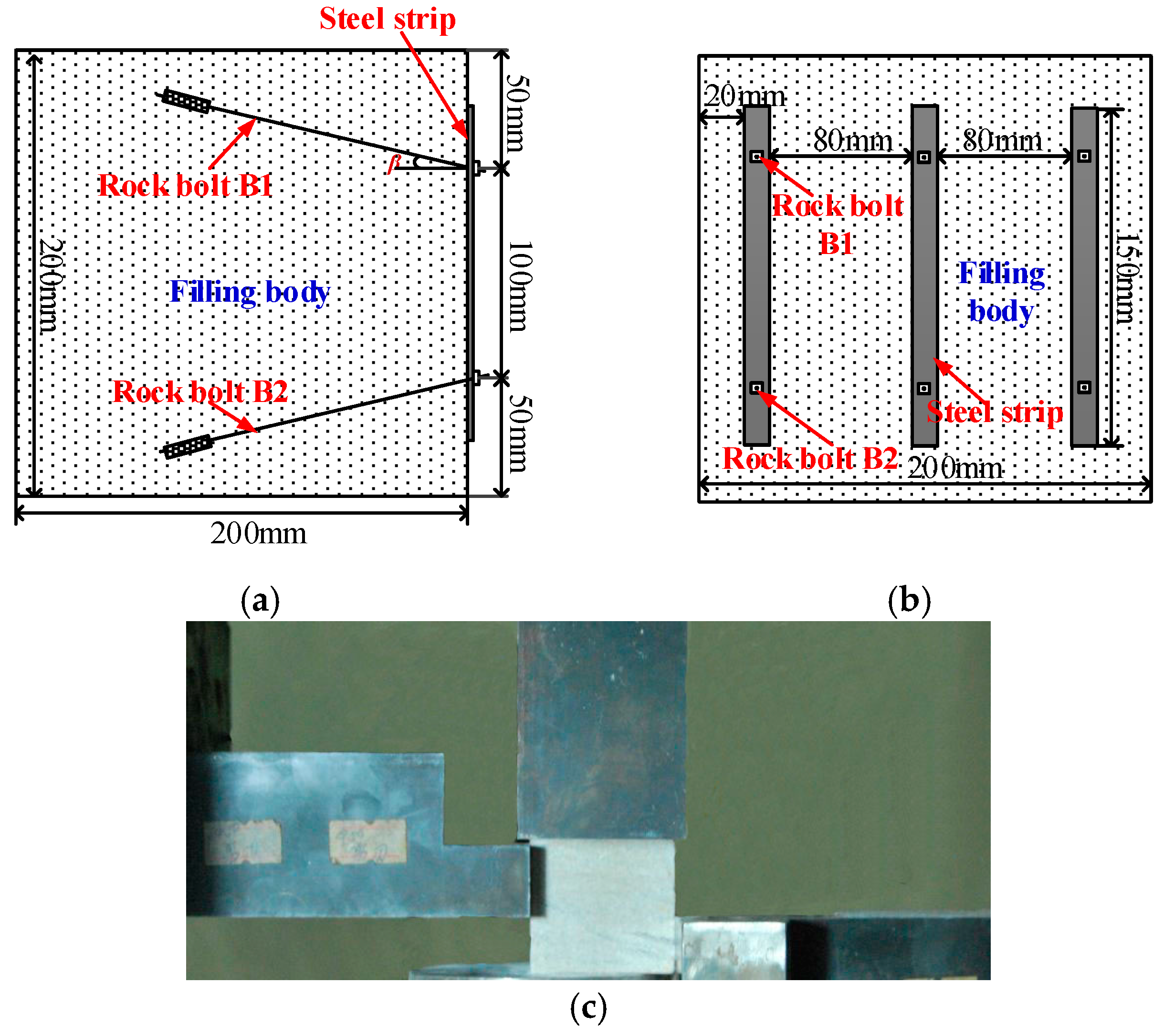
To improve the shear-resistance of the filling body, we proposed a roadside filling body–truss support structure, as shown in Figure 11. This truss support structure is composed of three anchor bolts and a steel strip. Therein, two inclined anchor bolts (B1 and B2) are anchored between the roof and floor, while the third anchor bolt (B3) is fixed in the filling body and lies parallel to the coal seam. These three anchor bolts are fastened to the steel strip through the connector. This support structure can provide lateral support resistances qL, F1, and F2 for the filling body, among which qL is the force acting on the steel strip on the roadside filling body in the form of a uniform load, F1 represents the constraining force provided by the inclined bolts B1 and B2 to the filling body, and F2 is the constraining force offered by bolt B3 to the filling body. Meanwhile, the truss support structure anchors the filling body with the roof and floor strata, which improves the shear strength of the filling body.
5. Laboratory Experiment on Shear Performance of Backfill–Truss Support Structure
5.1. Experimental Materials
Based on the similarity principle, steel wires and a thin piece of sheet steel (45 steel) were used to simulate the anchor bolts and steel strip, respectively. The mechanical property parameters of the steel wires and thin piece of sheet steel are listed in Table 2. A mixture of barite powder and rosin alcohol solution was used as the anchoring agent. In addition, the support structure had a geometric similarity of 1:10. Table 3 lists the diameters of the anchor bolts and boreholes, along with the intervals and lengths of the anchor bolts, while Table 4 lists the geometrical parameters of the steel strip.
Approximately 28 days after casting, the roadside filling material used in the field test had a uniaxial compressive strength of 32 MPa (see Figure 2) and an elastic modulus of 11.2 GPa. Based on the similarity principle, the similarity ratio was found to have been 10:1. The components and proportions of the filling material are listed in Table 5. According to the constant of geometric similarity, standard cube specimens with widths, heights, and lengths of 200 mm were prepared using this material. Afterwards, the specimens were placed in a curing box at 25 °C and a relative humidity of 90% for 28 days.
To investigate the shear performance of the backfill–truss support structure, the truss and filling body were combined in this experiment. To prepare the backfill–truss support structure, holes were drilled in the filling body and steel strip. After the holes were cleaned, the anchoring agent was slowly injected into the holes to fix the anchor bolts and steel strip, as illustrated in Figure 12.
5.2. Experimental Schemes
Pressure-shear testing was conducted on the filling body specimens (prepared according to the parameters listed in Table 1 and a curing age of 28 days) and backfill–truss support structure, using an RLJW-2000 rock-pressure testing machine (Chaoyang Test Instrument Co., Ltd., Changchun, China). By changing the inclination angles (β) of anchor bolts B1 and B2 in the truss support structure, five test schemes were designed using β values of 90° (scheme 1), 70° (scheme 2), 60° (scheme 3), 45° (scheme 4), and 30° (scheme 5).
In each scheme, (1) the shear force was applied to the specimens under initial displacement control and the loading was stopped when the shear force reached 0.5 kN; (2) a normal stress of 5.12 kN (approximately 40% of the compressive strength of the filling body) was applied using the stress control method; and (3) Li et al. [27] established the relationship between the advance velocity and loading rate of the testing machine. According to these findings, the shear force was applied to the specimens at a cross-head speed of 0.25 mm/min until the specimens lost their load-carrying ability. By comparing the shear strengths of the conventional specimens and backfill–truss support structure, we analyzed the influences of the truss support structure and inclination angle β of the anchor bolts on the shear strength of the filling body.
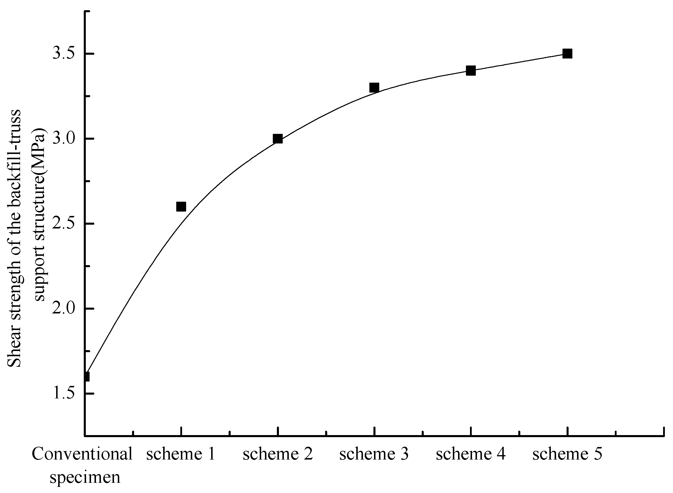
5.3. Experimental Results
The experimental results are shown in Figure 13. Compared with conventional filling bodies, the backfill–truss support structure exhibited a larger ultimate shear strength. The ultimate shear strength of the backfill–truss support structure increased with a decrease in the angle of the inclined anchor bolts. When the anchor bolt was tilted at an angle of 60°, its shear strength reached 3.3 MPa, which was 107.54% higher than that of the filling bodies without truss support structures.
6. Field Application
To verify the supporting effect of the backfill–truss support structure, field investigations were conducted on the No. 41101 main transportation roadway in the Awuzisu coal mine, Xinjiang (red region, Figure 1). The specific geological and mining conditions of this roadway are shown above.
6.1. Parameters of Backfill–Truss Support Structure
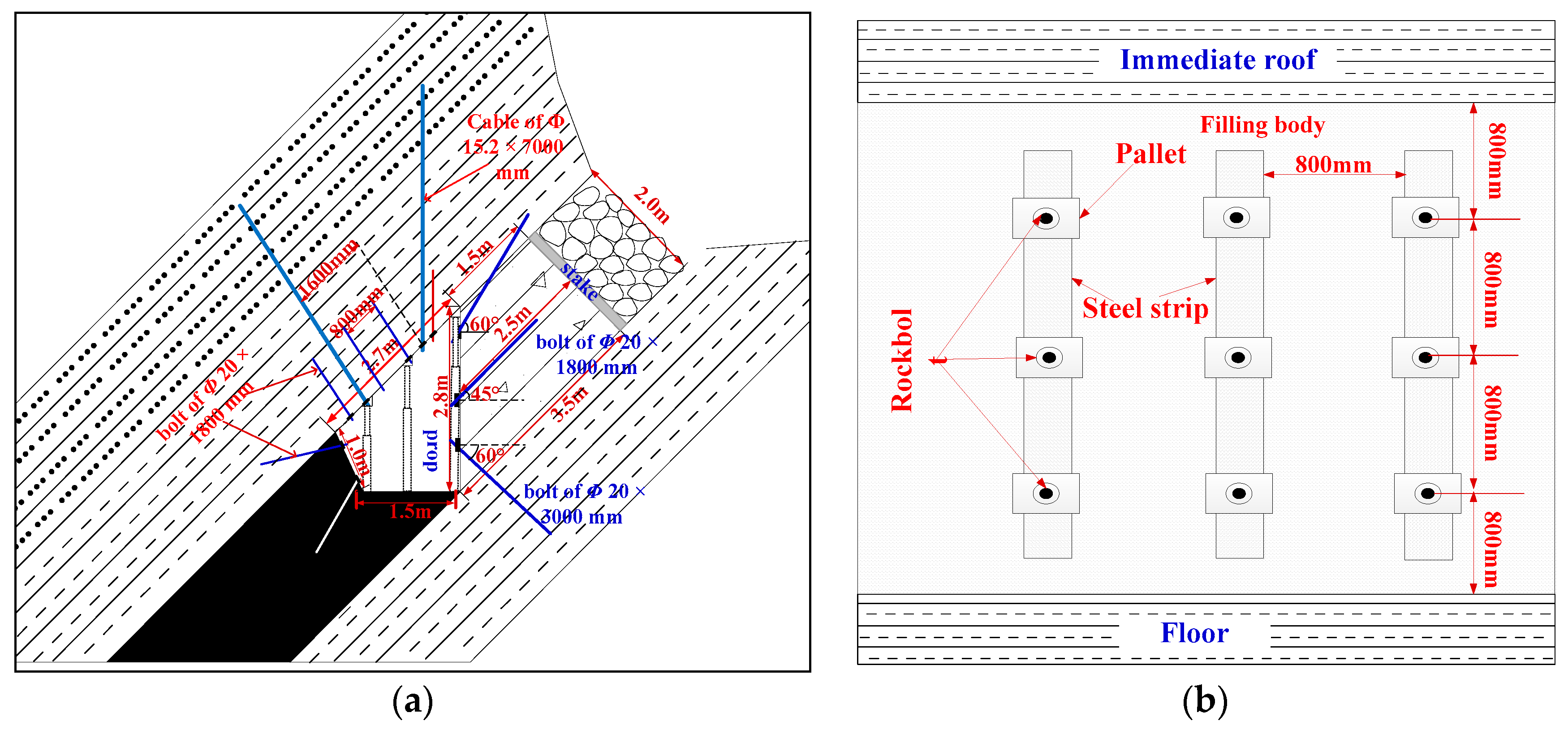
The roof and coal walls are supported according to the parameters set for the original roadway. Beside the roadway, cement-based paste was used to construct a truss support structure with the filling wall being 1.5 m, 3.5 m, and 2.5 m thick in the upper, lower, and middle parts, respectively. Figure 14 shows the backfill–truss support structure. The proportions of this filling material are listed in Table 1. Left-handed high-strength anchor bolts with a yield load of 171 kN and tensile load of 266 kN, containing no longitudinal reinforcement, were used. The bolts were 20 mm in diameter and required a pre-tightening force greater than 60 kN. The inclined anchor bolts in the upper and lower parts of the filling body were 3 m in length. Both had an inclination angle of 60°, while the anchor bolt in the middle part was 1.8 m long. Z2360 anchor agents with a length of 0.3 m were used to anchor the ends. In addition, a W-type steel strip with a width, length, and thickness of 220 mm, 2400 mm, and 2.5 mm, respectively, was used.
6.2. Construction Technology
The backfill–truss support structure in the No. 41101 main transportation roadway was established 3 m behind the working face using the filling technique. The specific construction procedure was as follows:
- (1)
- Advance support was undertaken on the working face using two rows of single hydraulic props erected in the intake airflow roadway and return airway of the working face. These props were arranged at row and column separations of 1000 × 1000 mm2, and the advance-support distance was maintained at 25 m (Figure 15). After the supports of the roadway face-end were normally removed, three rows of single hydraulic props were established in the roadway retained in the gob to temporarily support the working face. These props were fixed at 1000 mm intervals in both the rows and columns, and the supporting width was 4000 mm.
- (2)
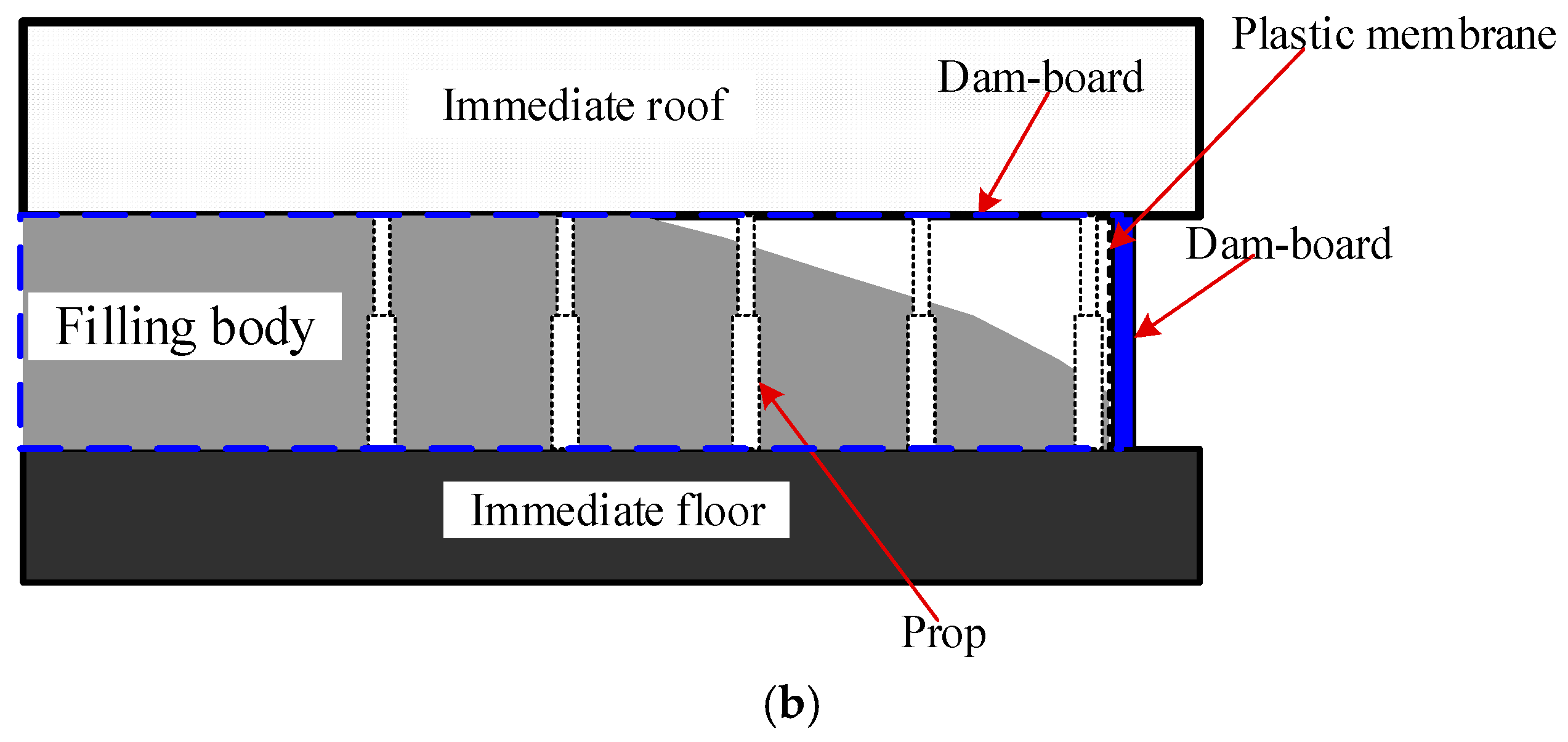
- After the working face was advanced by 3 m, densely arranged wooden pillars were used as substitutes for the single props in the side closest to the gob, followed by the construction of the filling frameworks. The lateral plate (2.8 m in height) was always perpendicular to the horizontal plane, while the inside plate was perpendicular to the inclined direction of the coal seam. Moreover, the distance between two plates in the floor strata was always 3.5 m (see Figure 15). To maintain the stability of the filling frameworks and roof, hydraulic props were fixed on one side of the lateral plate close to the retained roadway at intervals of 1 m along the advancing direction of the working face. To prevent cement grout from escaping by seepage, a plastic diaphragm was laid on the inner side of the filing plate.
- (3)
- After being uniformly mixed according to the proportions listed in Table 1, the filling materials were transported to the filling area through a pipeline beside the roadway to construct the roadside filling body.
- (4)
- Approximately four to five days after the filling body was first constructed, the roadside filling body was supported according to the designed parameters of the truss.
- (5)
- Steps 1 to 4 were repeated until the entire filling wall was constructed.
6.3. Application Effect
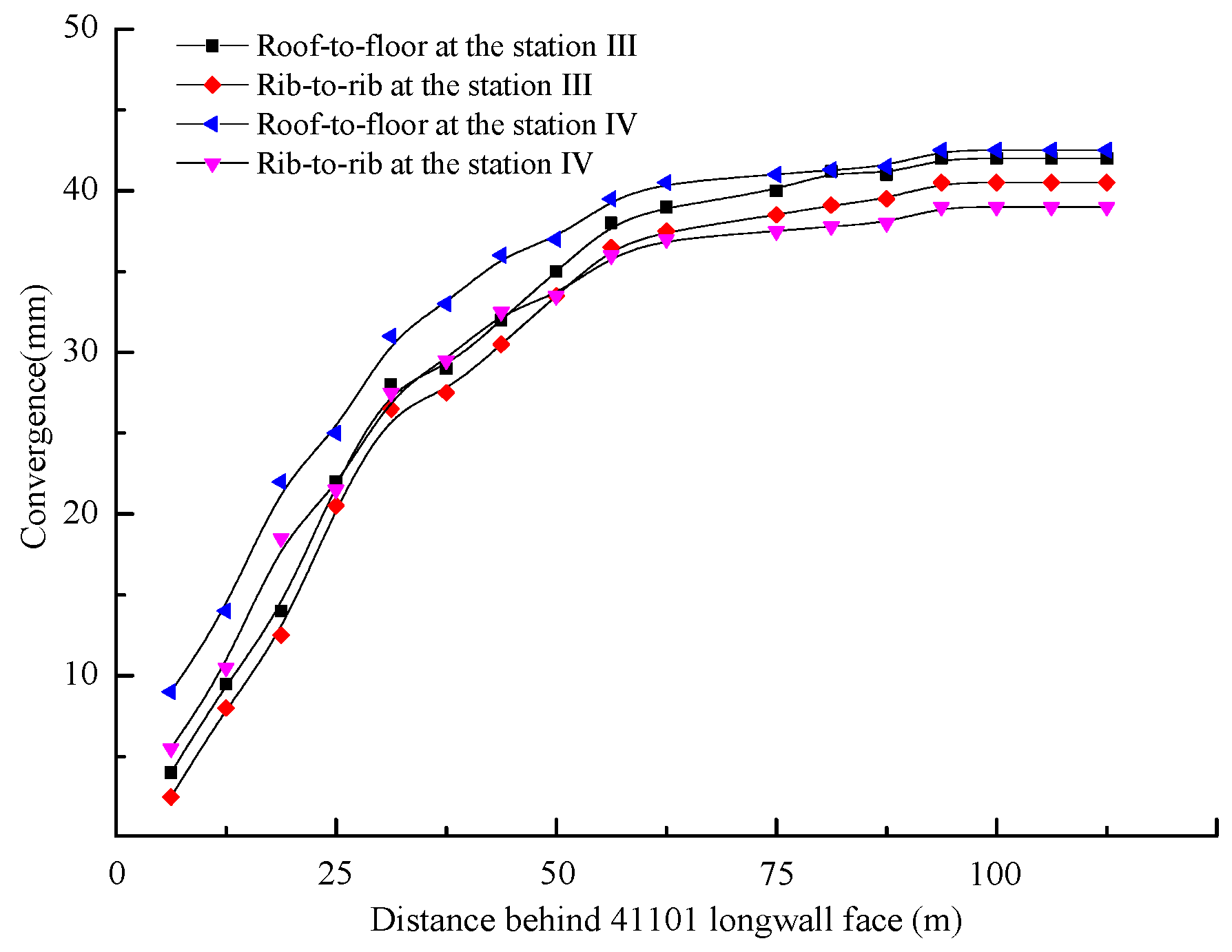
After working face No. 41101 was advanced by 300 m, the remaining roadway along the gob began to be supported using the backfill–truss support. Observation stations III and IV were respectively established at 130 m and 180 m behind the working face (see Figure 1a). The deformation (including convergence between the roof and floor, as well as that between the two walls of the roadway) of the surrounding rocks in the roadway was observed at the stations using a crossing method, as shown in Figure 6b. The monitoring results are presented in Figure 16.
When the backfill–truss support structure was applied, the deformation of the surrounding rocks gradually increased with the advance of the working face over distances of up to 40 m, with the maximum deformation of the surrounding rocks being 37 mm, as shown in Figure 16. The rate of deformation of the surrounding rocks gradually decreased when the working face was advanced by 50 m. Therefore, the truss support structure was found to improve the shear resistance of the cement-based filling body and the capacity to resist lateral deformation by integrating the filling body with the roof and floor strata. Consequently, we concluded that the roadside backfill–truss support structure could adapt to the large shear stresses caused by roof movement in the mining of steeply inclined coal seams.
7. Conclusions
1. After performing gob-side entry retention work for this working face, the roadside filling body in the gob-side entry retention area is expected to bear a large shear stress when the lateral main roof moves, sags, and compacts the rubble. In this stage, if the shear stress τ on the roadside filling body is larger than its ultimate shear strength τU, shear failure is expected to occur in the filling body.
2. By establishing mechanical models of the gob-side entry retention in a steeply inclined coal seam, we obtained an equation for calculating the shear stress on the roadside filling body after the roof strata had stabilized. Based on field investigations and laboratory experiments, some parameters were obtained, including the force acting on the main roof strata from the coal wall and the relationship between the axial bearing capacity and compression ratio of the rubble. On that basis, the shear stress on the roadside filling body of working face No. 41101 was found to be 15.89 MPa. If only the cement-based filling body was used as the roadside support, the maximum shear strength of the filling body was 12.38 MPa, which failed to satisfy the design requirement for shear strength.
3. The roadside backfill–truss support structure proposed in this paper was comprised of three anchor bolts and a steel strip. Therein, two inclined anchor bolts were anchored to the roof and floor, while the third anchor bolt was fixed to the filling body to lie parallel to the coal seam. These three anchor bolts were connected using the steel strip. A laboratory shear test indicated that the ultimate shear strength of the structure was 107.54% higher than that of a cement-based filling body when the dip angle of the inclined bolt was 60°. In addition, field monitoring showed that roof-to-floor and rib-to-rib convergences only reached 42 mm when the working face advanced by up to 50 m when using the roadside backfill–truss support structure in situ.
Acknowledgments
This study was supported by the National Natural Science Foundation of China (No. 51574154), the China Postdoctoral Science Foundation Funded Project (No. 2016M592220), and the Qingdao Postdoctoral Applied Research Project (No. 2015198). Postgraduate Innovative Fund Project of College of Mining and Safety Engineering (KYKC17005). The authors express their sincere thanks to the reviewers for their helpful comments and suggestions for improving this paper.
Author Contributions
Jianguo Ning and Jun Wang developed the design solution and conducted the data analysis. Considering the contribution of Jianguo Ning and Jun Wang on the manuscript, they contributed equally to this paper and should be considered co-first authors. Tengteng Bu and Xuesheng Liu conducted the laboratory and analytical work in the interpretation of data. Shanchao Hu designed the laboratory work and revised the paper.
Conflicts of Interest
The authors declare no conflict of interest.
References
- Guo, Z.B.; Wang, J.; Cao, T.P.; Chen, L.; Wang, J. Research on key parameters of gob-side entry retaining automatically formed and pressure release in thin coal seam mining. J. China Univ. Min. Technol. 2016, 45, 879–885. [Google Scholar]
- Tan, Y.L.; Yu, F.H.; Ning, J.G. Design and construction of entry retention wall along a gob side under hard roof stratum. Int. J. Rock Mech. Min. Sci. 2015, 77, 115–121. [Google Scholar]
- Farmer, I.W. Deformation of Access Roadways and Roadside Packs in Coal Mines. Dev. Geotech. Eng. 1981, 32, 207–212. [Google Scholar]
- Abdelhadi, K.; Latifa, O.; Khadija, B. Valorization of mining waste and tailings through paste backfilling solution, Imiter operation, Morocco. Int. J. Min. Sci. Technol. 2016, 26, 511–516. [Google Scholar]
- Li, L.; Dubé, J.S.; Aubertin, M. An Extension of Marston’s Solution for the Stresses in Backfilled Trenches with Inclined Walls. Geotech. Geol. Eng. 2013, 31, 1027–1039. [Google Scholar] [CrossRef]
- Zhang, Z.Z.; Bai, J.B.; Chen, Y. An innovative approach for gob-side entry retention in highly gassy fully-mechanized longwall top-coal caving. Int. J. Rock Mech. Min. Sci. 2015, 80, 1–11. [Google Scholar]
- Tan, Y.L.; Yu, F.H.; Ning, J.G. Adaptability theory of roadside support in gob-side entry retention and its supporting design. J. China Coal Soc. 2016, 42, 376–382. [Google Scholar]
- He, M.C.; Zhu, G.L.; Guo, Z.B. Longwall mining “cutting cantilever beam theory” and 110 mining method in China-The third mining science innovation. J. Rock Mech. Geotech. Eng. 2015, 7, 483–492. [Google Scholar] [CrossRef]
- Wang, X.Q.; Zhang, N.; Kan, J.G.; Zhang, N.C. Cracking mechanism and control strategy of concrete roadside wall with large scale. J. China Univ. Min. Technol. 2017, 46, 237–243. [Google Scholar]
- Kang, H.P.; Niu, D.L.; Zheng, Z. Deformation characteristics of surrounding rock and supporting technology of gob-side entry retention in deep coal mine. Chin. J. Rock Mech. Eng. 2010, 29, 1977–1987. [Google Scholar]
- Zhang, N.; Yuan, L.; Han, C.L. Stability and deformation of surrounding rock in pillarless gob-side entry retention. Saf. Sci. 2012, 50, 593–599. [Google Scholar] [CrossRef]
- Zhou, B.J.; Xu, J.H.; Zhao, M.S. Stability study on naturally filling body in gob-side entry retention. Int. J. Min. Sci. Technol. 2012, 22, 423–427. [Google Scholar] [CrossRef]
- Ning, J.G.; Wang, J.; Liu, X.S. Soft-strong supporting mechanism of gob-side entry retention in deep coal seams threatened by rockburst. Int. J. Min. Sci. Technol. 2014, 24, 805–810. [Google Scholar] [CrossRef]
- Gao, M.Z. Similarity model test of strata movement with steep seam. Chin. J. Rock Mech. Eng. 2004, 23, 441–445. [Google Scholar]
- Yun, D.F.; Liu, Z.; Cheng, W.D.; Fan, Z.D.; Wang, D.F.; Zhang, Y.H. Monitoring strata behavior due to multi-slicing top coal caving longwall mining in steeply dipping extra thick coal seam. Int. J. Min. Sci. Technol. 2017, 27, 179–184. [Google Scholar] [CrossRef]
- Ning, J.G.; Ma, P.F.; Liu, X.S. Supporting mechanism of “yielding-supporting” beside roadway maintained along the gob under hard rocks. J. Min. Saf. Eng. 2013, 30, 369–374. [Google Scholar]
- Alejano, L.R.; Ramı́rez-Oyanguren, P.; Taboada, J. FDM predictive methodology for subsidence due to flat and inclined coal seam mining. Int. J. Rock Mech. Min. Sci. 1999, 36, 475–491. [Google Scholar] [CrossRef]
- Zhang, Y.Q.; Tang, J.X.; Xiao, D.Q. Spontaneous caving and gob-side entry retention of thin seam with large inclined angle. Int. J. Min. Sci. Technol. 2014, 24, 441–445. [Google Scholar] [CrossRef]
- Wang, J.A.; Jiao, J.L. Criteria of support stability in mining of steeply inclined thick coal seam. Int. J. Rock Mech. Min. Sci. 2016, 82, 22–35. [Google Scholar] [CrossRef]
- Zhang, D.S.; Mao, X.B.; Ma, W.D. Testing study on deformation features of surrounding rocks of gob-side entry retention in fully-mechanized coal face with top-coal caving. Chin. J. Rock Mech. Eng. 2002, 23, 331–334. [Google Scholar]
- Chen, Y.; Bai, J.B.; Wang, X.Y. Support technology research and application inside roadway of gob-side entry retention. J. China Coal Soc. 2012, 36, 903–910. [Google Scholar]
- Schumacher, F.P.; Kim, E. Evaluation of directional drilling implication of double layered pipe umbrella system for the coal mine roof support with composite material and beam element methods using FLAC3D. J. Min. Sci. 2014, 50, 335–348. [Google Scholar] [CrossRef]
- Zhang, D.H.; Li, H. Experimental study on compression performance of continuous grading gangue. J. Liaoning Tech. Univ. Nat. Sci. 2011, 30, 337–340. [Google Scholar]
- Tan, Y.L.; Liu, X.S.; Ning, J.G. In situ investigations on failure evolution of overlying strata induced by mining multiple coal seams. Geotech. Test. J. 2017, 40, 244–257. [Google Scholar] [CrossRef]
- Ning, J.G.; Wang, J.; Tan, Y.L.; Zhang, L.S.; Bu, T.T. In situ investigations into mining-induced overburden failures in close multiple-seam longwall mining: A case study. Geomech. Eng. 2017, 12, 657–673. [Google Scholar]
- Li, W.F.; Bai, J.B.; Peng, S.S. Numerical modeling for yield pillar design: A case study. Rock Mech. Rock Eng. 2015, 48, 305–318. [Google Scholar] [CrossRef]
- Li, H.T.; Zhou, H.W.; Jiang, Y.D. An Evaluation Method for the Bursting Characteristics of Coal under the Effect of Loading Rate. Rock Mech. Rock Eng. 2016, 49, 1–11. [Google Scholar]
Figure 1.
Layout of working face No. 41101: (a) layout of working face; (b) layout of observation stations; (c) lithological profile of roof strata; and (d) section a-a.
Figure 1.
Layout of working face No. 41101: (a) layout of working face; (b) layout of observation stations; (c) lithological profile of roof strata; and (d) section a-a.
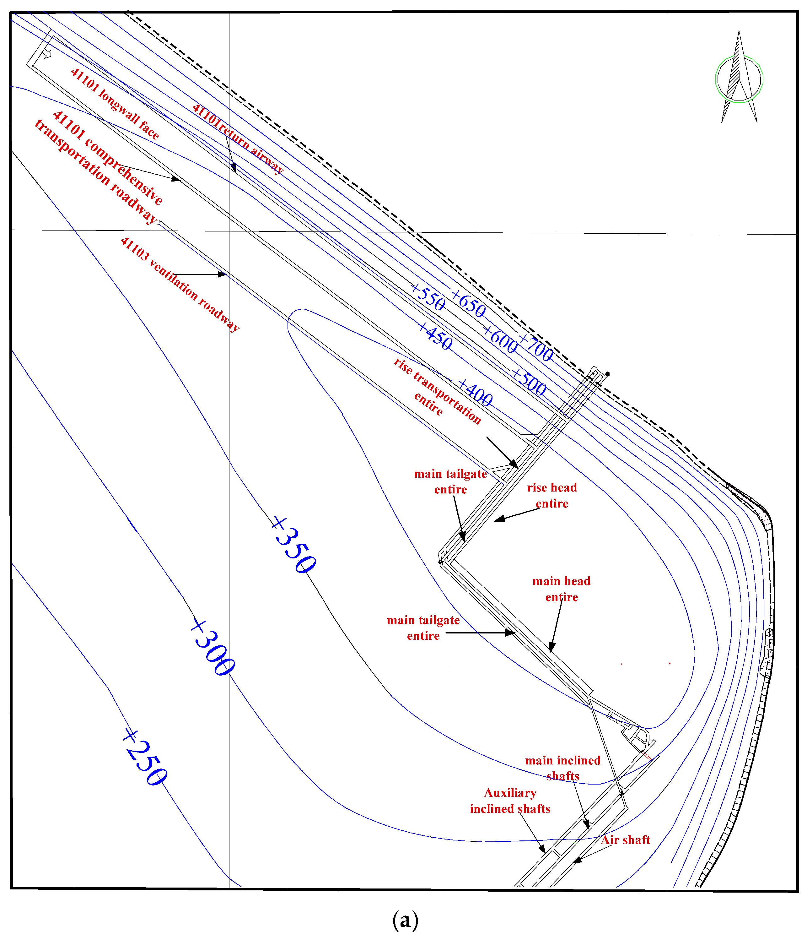

Figure 2.
Relationships between strengths and curing time of cement-based filling body: (a) relationship between uniaxial compressive strength and age and (b) relationship between shear strength and age.
Figure 2.
Relationships between strengths and curing time of cement-based filling body: (a) relationship between uniaxial compressive strength and age and (b) relationship between shear strength and age.
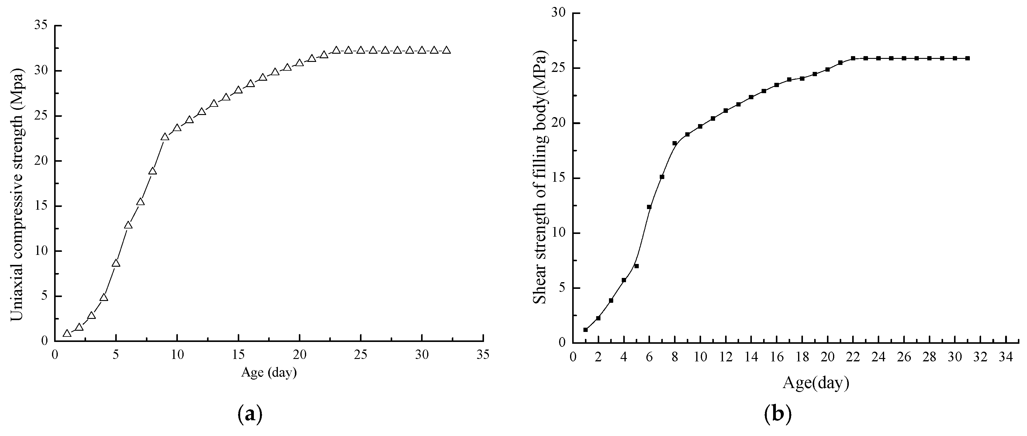
Figure 3.
Deformation of surrounding rocks of gob-side entry retention work (cemented materials were used to fill space in frameworks).
Figure 3.
Deformation of surrounding rocks of gob-side entry retention work (cemented materials were used to fill space in frameworks).
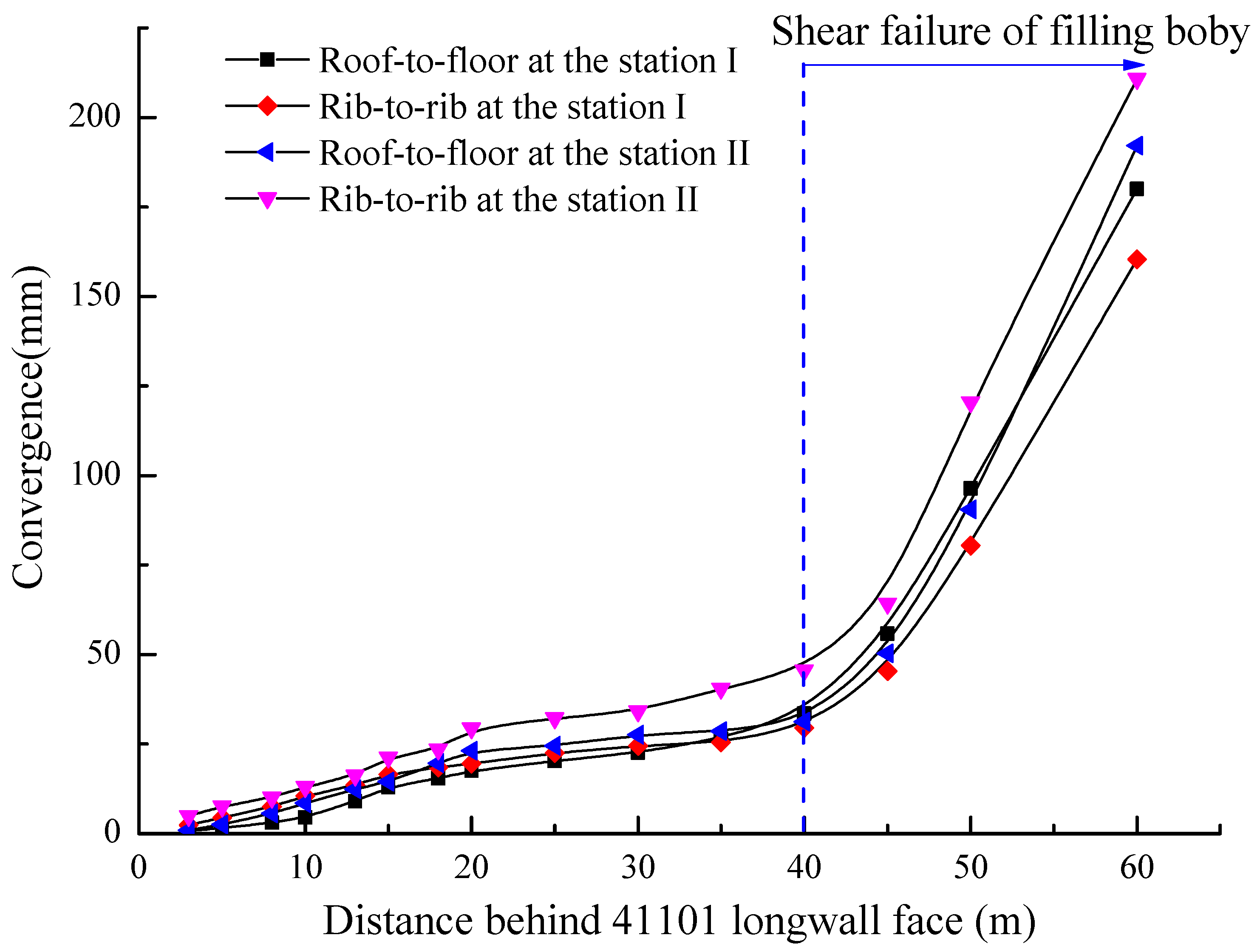
Figure 4.
Mechanical model of roof of gob-side entry retention work in steeply inclined coal seam.
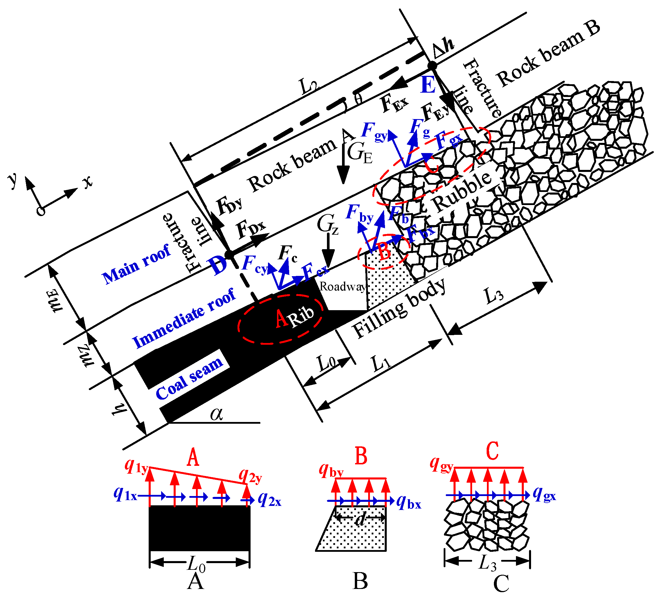
Figure 5.
Mechanical model of filling body of gob-side entry retention work in steeply inclined coal seam.
Figure 5.
Mechanical model of filling body of gob-side entry retention work in steeply inclined coal seam.

Figure 6.
Layout of field monitoring stations: (a) layout of observation stations; (b) profile of Station I; and (c) layout of borehole stress-meters.
Figure 6.
Layout of field monitoring stations: (a) layout of observation stations; (b) profile of Station I; and (c) layout of borehole stress-meters.

Figure 7.
Pressure curves in coal mass.

Figure 8.
Device and molds used in loading test of rubble.
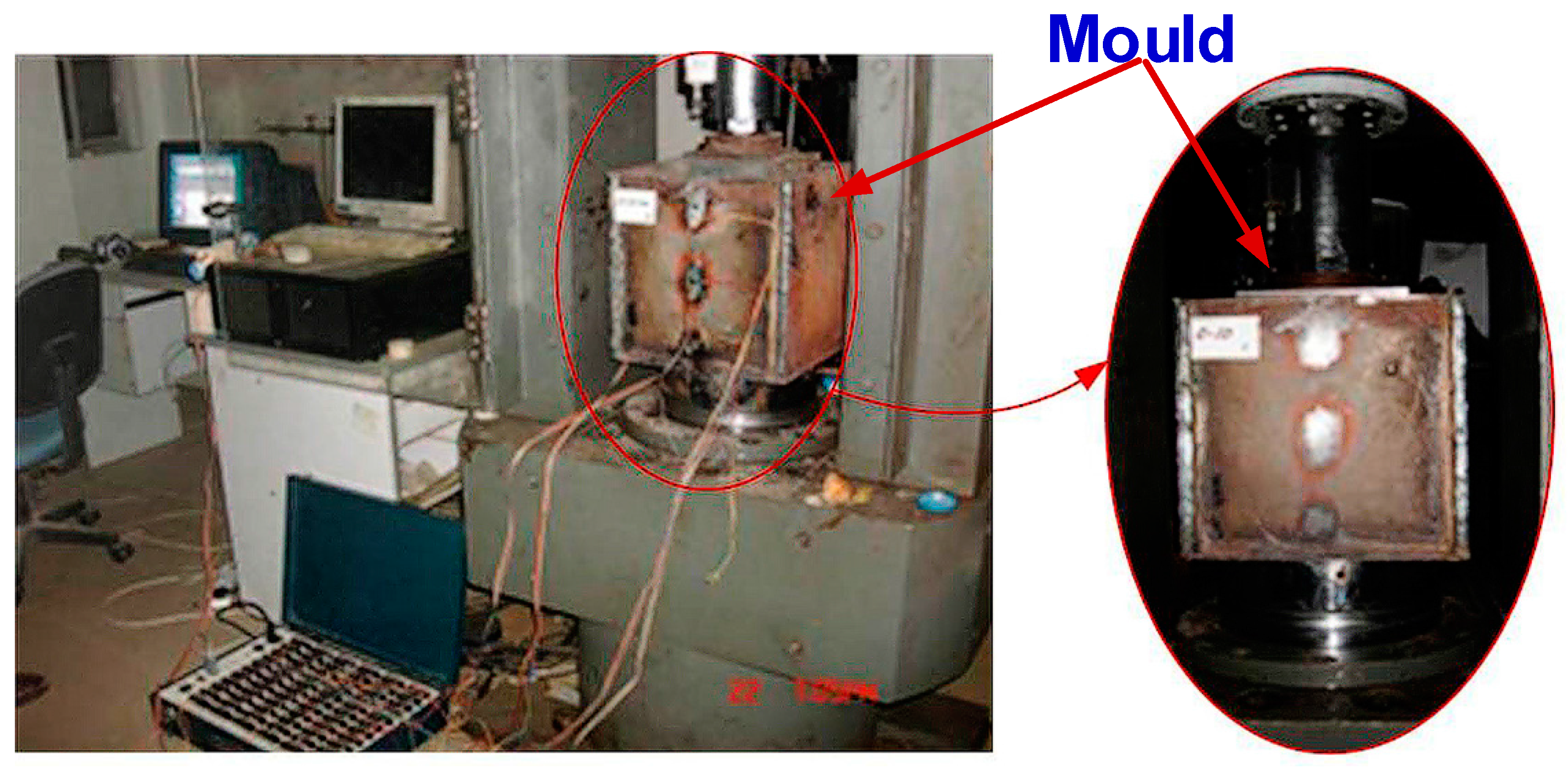
Figure 9.
Curve relating bearing capacity to compression ratio of rubble in gob.
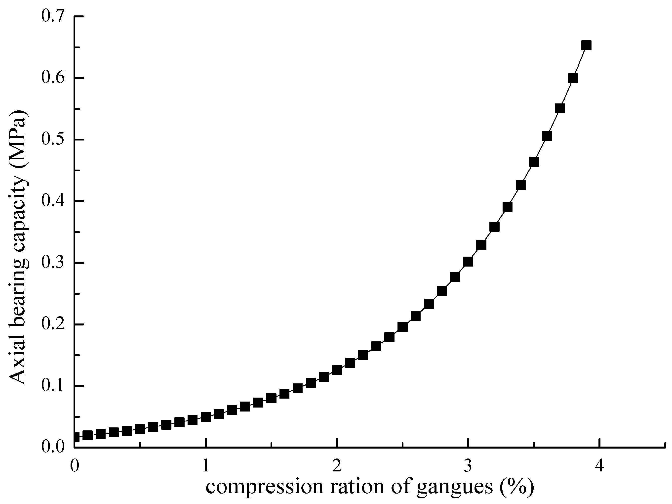
Figure 10.
Thrust from rubble inside gob on filling body.
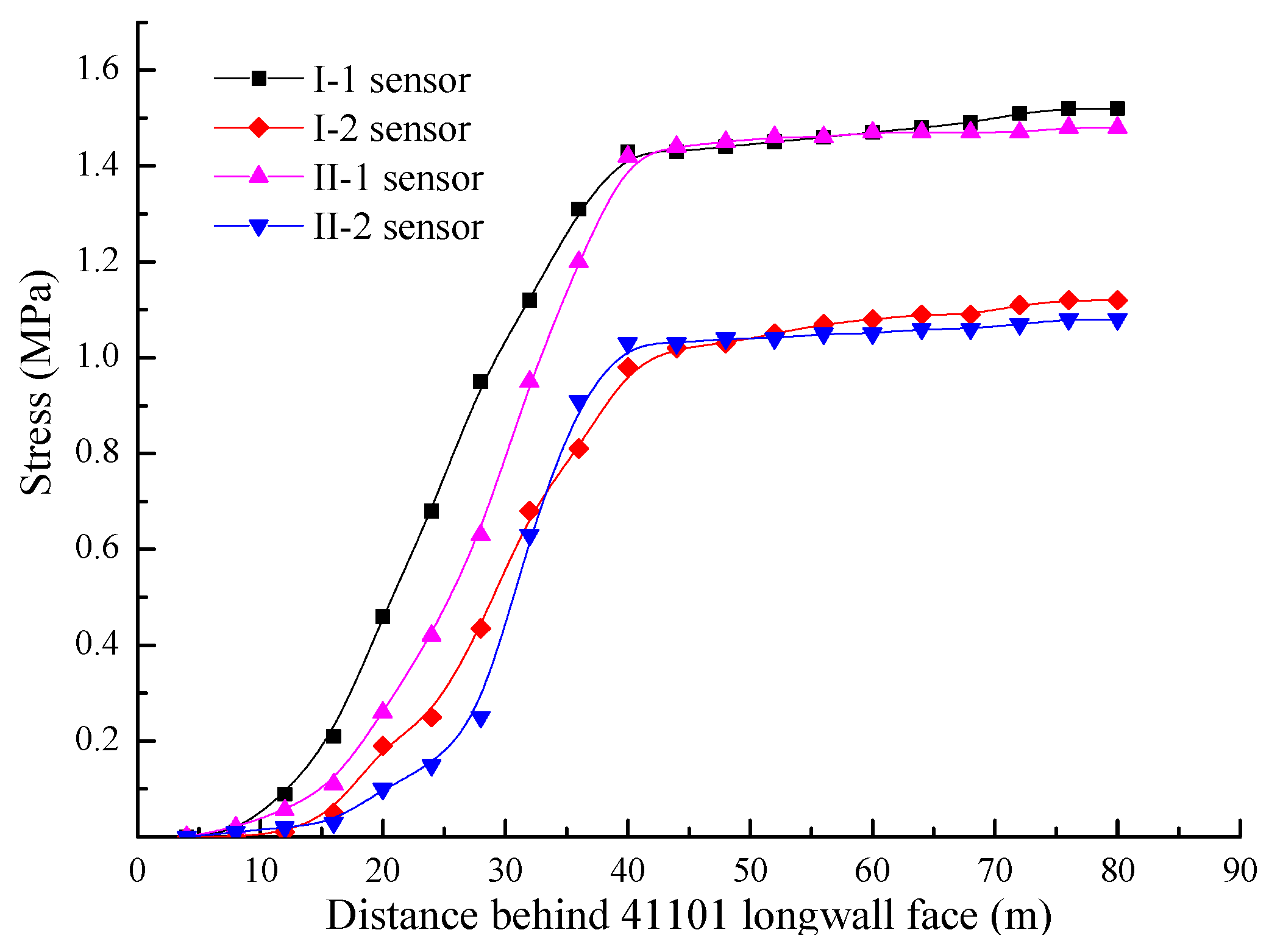
Figure 11.
Filling body–truss support structure beside remaining roadway along gob.
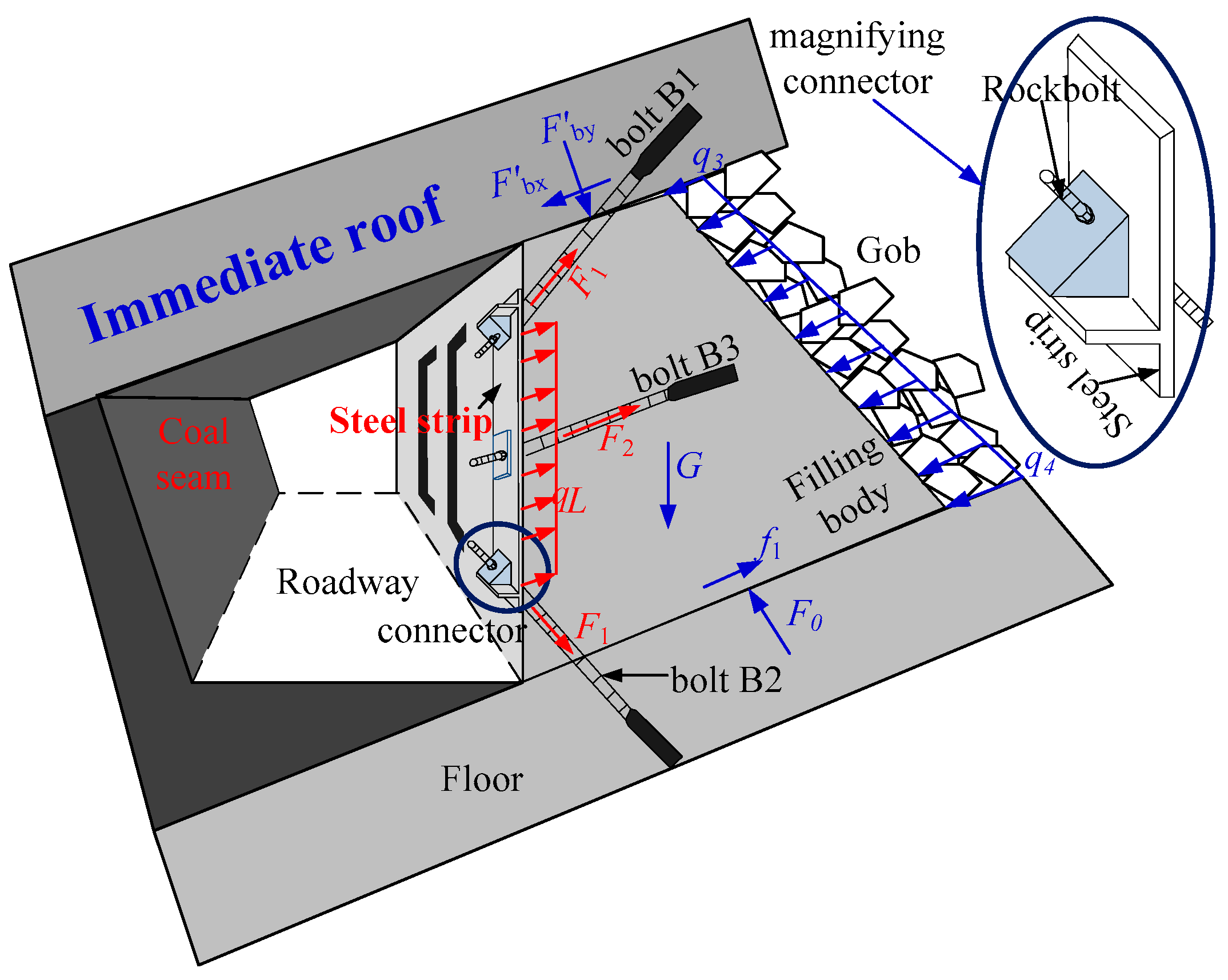
Figure 12.
Direct shear test and size of backfill–truss support structure. (a) Front view; (b) side view; (c) enlargement of local areas.
Figure 12.
Direct shear test and size of backfill–truss support structure. (a) Front view; (b) side view; (c) enlargement of local areas.

Figure 13.
Results of direct shear test of backfill–truss support structure.

Figure 14.
Backfill–truss support structure: (a) front view and (b) right view.

Figure 15.
Filling retained roadway along gob of No. 41101 main transportation roadway: (a) plan view and (b) cross-section A-A.
Figure 15.
Filling retained roadway along gob of No. 41101 main transportation roadway: (a) plan view and (b) cross-section A-A.
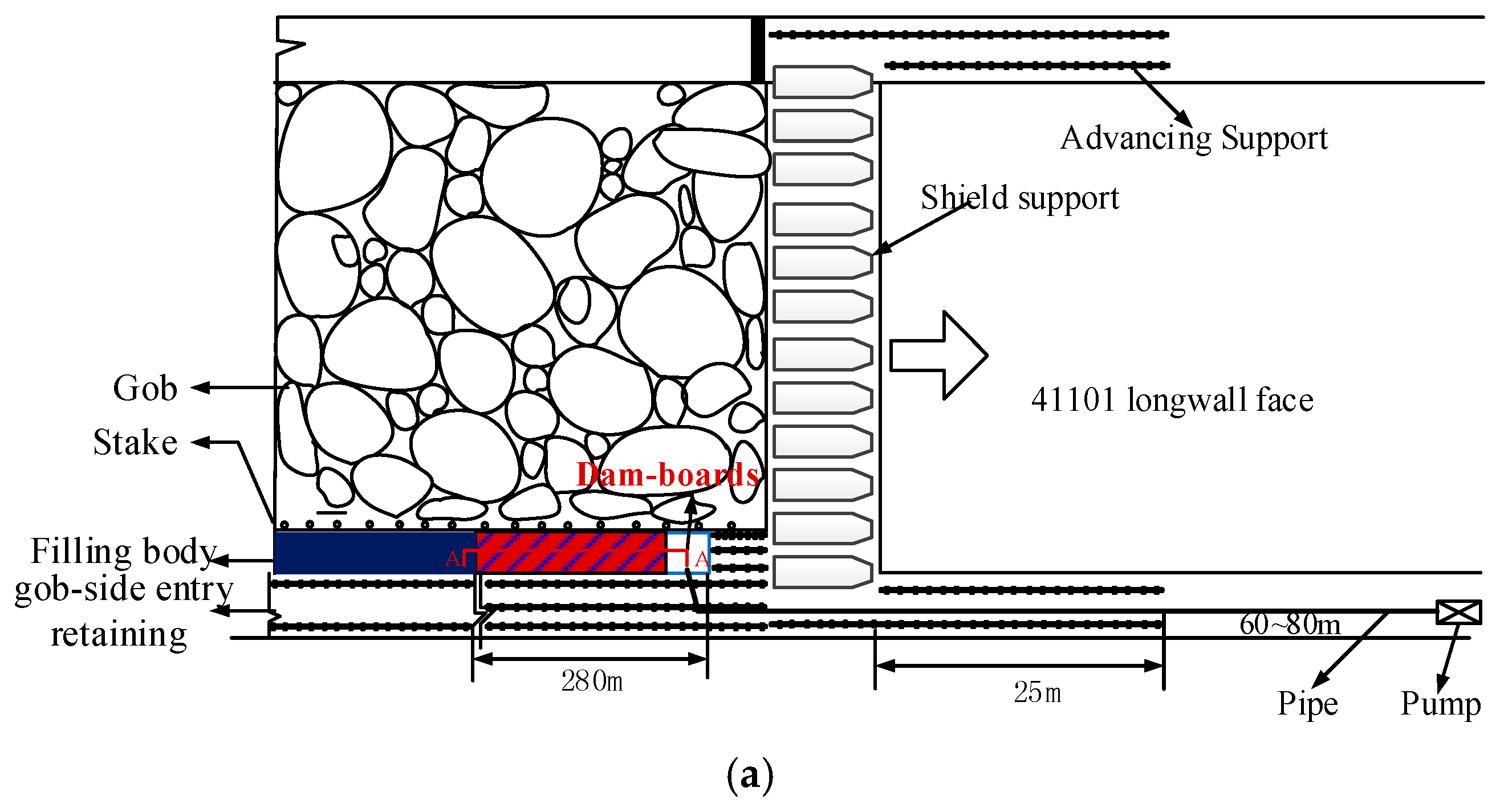

Figure 16.
Deformation of surrounding rocks in backfill–truss supported roadway.

Table 1.
Components and proportions of paste materials.
| Proportions of the Paste Filling Materials (kg/t) | Stone Granularity (mm) | |||||||
|---|---|---|---|---|---|---|---|---|
| Water | Cement | Fly Ash | Gangue | River-Sand | Stone | Early Strength Agent | Water-Reducing Agent | |
| 134 | 164 | 44 | 85 | 227 | 340 | 2.8 | 3.2 | 5–10 |
Table 2.
Mechanical parameters of anchor bolts, steel strip, and 45 steel.
| Parameters | Tension (MPa) | Shear Strength (MPa) | Anchoring Force (MPa) | Elastic Modulus (GPa) | Extensibility | |
|---|---|---|---|---|---|---|
| Element | ||||||
| Rock bolt | 200–600 | 260–600 | ≥50 | 200 | ≥16% | |
| Steel strip | 350–400 | / | / | 200 | ≥16% | |
| Steel wires, thin sheet steel | 600 | 400 | 80 | 210 | ≥16% | |
Table 3.
Geometrical parameters of truss support structure.
| Parameters | Borehole Diameter (mm) | Bolt Diameter (mm) | Space (mm) | Bolt Length (mm) | ||
|---|---|---|---|---|---|---|
| Element | Bolt B1 and Bolt B2 | Bolt B3 | ||||
| Engineering prototype | 30 | 20 | 800 | 3000 | 1800 | |
| Truss support structure | 3 | 2 | 80 | 300 | 180 | |
Table 4.
Geometrical parameters of steel strip.
| Type | Width (mm) | Thickness (mm) | Length (mm) | Space (mm) | Diameter (mm) |
|---|---|---|---|---|---|
| Engineering steel strip | 280 | 32 | 3300 | 800 | 30 |
| Thin sheet steel | 28 | 3.2 | 330 | 80 | 3 |
Table 5.
Proportions and parameters of different materials and physical characteristics of similar materials.
Table 5.
Proportions and parameters of different materials and physical characteristics of similar materials.
| I:B:S | G% | β | RA% | Unit Weight (kN/m3) | USC (MPa) | Elastic Modulus (MPa) |
|---|---|---|---|---|---|---|
| 1:0.25:0.22 | 2.5 | 25% | 5.0% | 2.80 | 3.29 | 1119.66 |
Remark: I, B, S represent iron powder, barite, and sand, respectively; G%, β, and RA% the total weight percentages of gypsum, rosin, and alcohol, respectively.
© 2017 by the authors. Licensee MDPI, Basel, Switzerland. This article is an open access article distributed under the terms and conditions of the Creative Commons Attribution (CC BY) license (http://creativecommons.org/licenses/by/4.0/).
Share and Cite
MDPI and ACS Style
Ning, J.; Wang, J.; Bu, T.; Hu, S.; Liu, X. An Innovative Support Structure for Gob-Side Entry Retention in Steep Coal Seam Mining. Minerals 2017, 7, 75. https://doi.org/10.3390/min7050075
AMA Style
Ning J, Wang J, Bu T, Hu S, Liu X. An Innovative Support Structure for Gob-Side Entry Retention in Steep Coal Seam Mining. Minerals. 2017; 7(5):75. https://doi.org/10.3390/min7050075
Chicago/Turabian StyleNing, Jianguo, Jun Wang, Tengteng Bu, Shanchao Hu, and Xuesheng Liu. 2017. "An Innovative Support Structure for Gob-Side Entry Retention in Steep Coal Seam Mining" Minerals 7, no. 5: 75. https://doi.org/10.3390/min7050075
Note that from the first issue of 2016, this journal uses article numbers instead of page numbers. See further details here.