Effect of Mica and Hematite (001) Surfaces on the Precipitation of Calcite


1
NASA Astrobiology Institute, Department of Geoscience, University of Wisconsin—Madison, Madison, WI 53706, USA
2
Department of Chemistry, The George Washington University, Washington, DC 20052, USA
*
Author to whom correspondence should be addressed.
Minerals 2018, 8(1), 17; https://doi.org/10.3390/min8010017
Submission received: 17 November 2017
/
Revised: 31 December 2017
/
Accepted: 9 January 2018
/
Published: 12 January 2018
(This article belongs to the Special Issue Fundamentals and Frontiers in Mineralogy)
Abstract
:The substrate effect of mica and hematite on the nucleation and crystallization of calcite was investigated using scanning electron microscope (SEM), X-ray diffraction (XRD), and electron backscatter diffraction (EBSD) methods. On mica, we found, in the absence of Mg2+, the substrates’ (001) surfaces with hexagonal and pseudo-hexagonal two-dimensional (2-D) structure can affect the orientation of calcite nucleation with calcite (001) ~// mica (001) and calcite (010) ~// mica (010) to be the major interfacial relationship. On hematite, we did not observe frequent twinning relationship between adjacent calcite gains, but often saw preferentially nucleation of calcite at surface steps on hematite substrate. We suggest that calcite crystals initially nucleate from the Ca2+ layers adsorbed on the surfaces. The pseudo-hexagonal symmetry on mica (001) surface also leads to the observed calcite (001) twinning. A second and less common orientation between calcite {104} and mica (001) was detected but could be due to local structure damage of the mica surface. Results in the presence of Mg2+ show that the substrate surfaces can weaken Mg toxicity to calcite nucleation and lead to a higher level of Mg incorporation into calcite lattice.

1. Introduction
The most recent (2013) Intergovernmental Panel on Climate Change (IPCC) report cogently concluded that increased anthropogenic greenhouse gas emissions (CO2 being the leading component) are the extremely likely cause for the observed warming since 1950s when atmospheric pCO2 increased from ~300 ppm [1] to today’s level around 390 ppm [2,3], resulting in globe-wide changes, such as diminishing of polar ice and sea level rise [4]. Given the unlikely occurrence for alternative energy to replace fossil fuels in the immediate future, this conclusion reinforces the consensus that a carbon sequestration strategy needs to be implemented to curtail future CO2 rise. Geological sequestration, among all other possible choices, stand out to be the most widely advocated. By forming carbonate minerals, this approach contains CO2 in environmentally benign and stable forms for a geologically significant time-frame [5,6,7].
A key scientific question in geological sequestration is carbonate mineralization in existing geological formations (within which CO2 is injected and migrates), particularly templated carbonate formation on other minerals. While there is a plethora of literature work concerning carbonates crystallization on carbonate seeds or on structured organic surfaces [8,9,10,11,12,13], only a few studies have dealt with the effect of non-carbonate minerals on carbonate nucleation and crystallization [14,15]. In the present work, we examine the epitaxial growth of CaCO3 polymorphs on biotite, muscovite, and hematite to evaluate the effect of geometry match between functional and binding groups on the substrates’ basal (001) face and structures of calcite surfaces.
2. Materials and Methods
2.1. Synthesis of Calcite on (001) Surfaces of Mica and Hematite
All experiments utilized well-crystallized single-phase biotite (from Bancroft, ON, Canada (Ward Scientific, 46-1190)), muscovite (from Stoneham, MA, USA), and hematite specularite (UW Mineralogy Collection 5742) with well-developed flat (001) surfaces. The composition of the biotite was determined using a Cameca SX51 electron microprobe (CAMECA, Gennevilliers, France) with mineral standards. Oxidation state of Fe in Bancroft biotite was calculated based on Mössbauer spectra. The biotite contained 16.29% FeO and had composition (K0.980, Na0.025)(Fe2+0.996, Fe3+0.222Mg1.663, Ti0.117)(Si3.048, Al0.812, Ti0.140)O10(OH1.02, F0.98) [16]. The unit cell parameters were obtained by XRD (Rigaku, Tokyo, Japan) using the Rietveld method, with a = 5.337 Å, b = 9.234 Å, c = 10.191 Å, and β = 100.2°.
The biotite and muscovite thin flakes (~0.5 cm in diameter) were prepared with clean scissors at room temperature. The mica and hematite substrates were glued to the wall of vessels using nail polish in all experiments to keep them vertical throughout the duration of the experiments and prevent physical settlement of calcium carbonate onto the substrates (Figure 1).
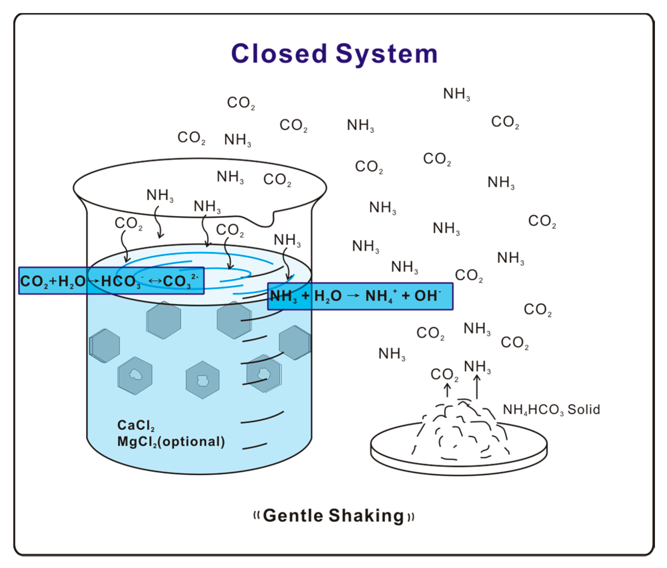
A free drift experiment [17,18,19,20,21,22] was used to carry out calcite crystallization. A vessel containing 1.5 mM/L CaCl2 solution is exposed to NH4HCO3 solid in a closed environment on a shaking station at a rate of 10 rotations per minute. Decomposition of NH4HCO3 provides NH3 and CO2 gases, which diffuse and dissolve into the solution. Hydrolysis of NH3 then raises the solution pH, thereby shifting the equilibrium CO2 + H2O ↔ HCO3− ↔ CO32− forward to increase the concentration of CO32−, which reacts with Ca2+ to precipitate CaCO3 (Figure 1). The whole system was allowed to react for a time period of 24 h. Precipitated samples were collected and washed by deionized (DI) water before further examination. The final solution pH for biotite substrate experiments was around 8.5. Experiments with solutions of various Mg/Ca ratios (1:1, 2:1, 5:1, and 6:1) prepared using mixed MgCl2-CaCl2 agents were also conducted with experiment setups identical to the pure Ca2+ experiment.
2.2. X-ray Diffraction Analyses
Diffraction data were collected using a Rigaku Rapid II X-ray system with a 2-D image plate (Mo K-alpha radiation). The two-dimensional images were then integrated to produce conventional 2-theta-intensity patterns using Rigaku’s 2DP software (ver. 1.0, Rigaku, Tokyo, Japan). Samples were mounted on a glass fiber using silicone grease, and measured at 50 kV accelerating voltage, 50 mA current, 15 min exposure time, and 0.1 mm diameter beam collimator.
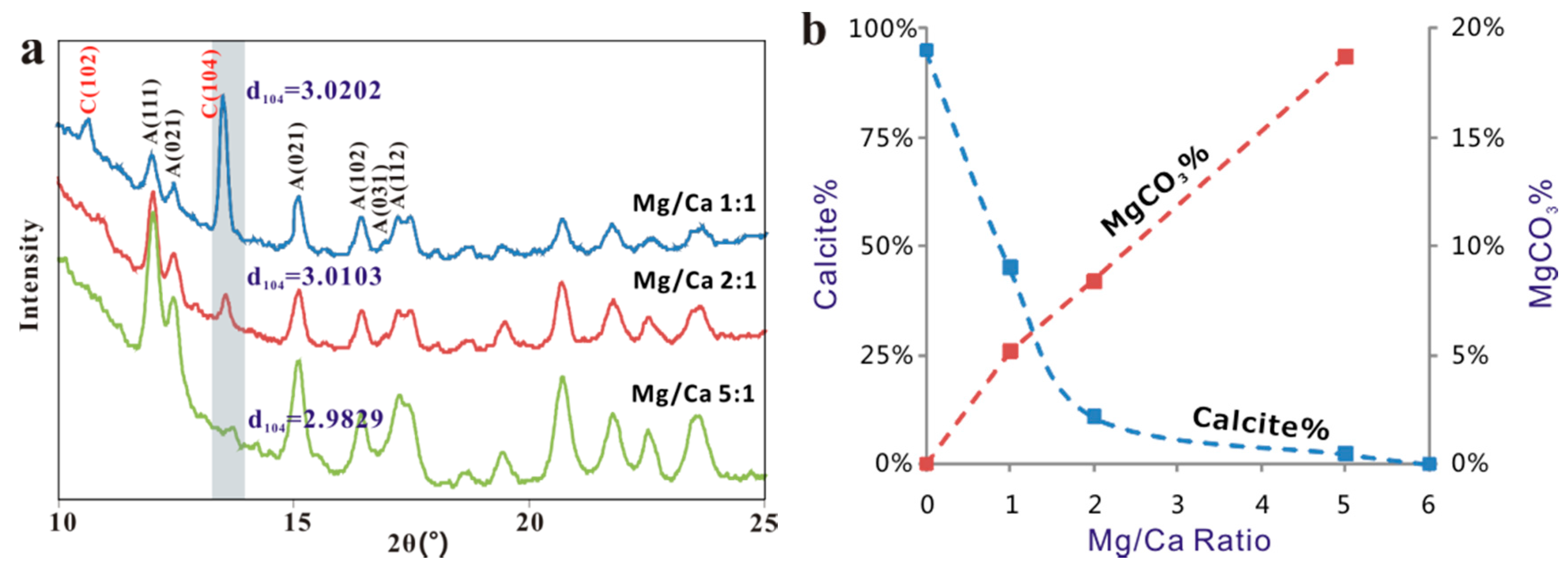
The relative abundance of individual polymorphs within each sample and cell parameters of mica were quantified by the Rietveld method. MDI’s Jade (version 9, MDI, Burbank, CA, USA) Whole Pattern Fitting (WPF) program was used for the Rietveld refinement analyses for this research. Increasing content of Mg in calcite will decrease its unit cell parameters and interspacing d104 value [23]. The d104 values of magnesium calcite, obtained from XRD analyses, in Mg2+-Ca2+ experiments were used for the calculation of Mg content based on an empirical curve for anhydrous Ca–Mg carbonate [23]. Composition of the Mg-bearing calcite on hematite was obtained by analyzing X-ray EDS spectra from the crystals and a dolomite standard on the same sample holder under same condition.
2.3. SEM and EBSD
Mica and hematite substrates with epitaxial calcium carbonate crystals were observed directly under a Hitachi S3400 SEM (Hitachi, Tokyo, Japan) equipped with energy-dispersive X-ray spectroscopy (EDS) using VP mode under 15 KV. SEM and EBSD (electron backscattered diffraction) (Hitachi, Tokyo, Japan) were performed the same samples where the SEM samples were tilted steeply (70°) towards the diffraction camera for EBSD analyses. All crystallographic data were collected at an accelerating voltage of 20 kV. Kikuchi patterns generated by diffracted electrons were processed using the software package CHANNEL 5 from Oxford Instruments Limited and results can be shown on stereographic projections. The EBSD patterns from calcite crystals were collected from areas close to the substrate to minimize height difference.
3. Results
3.1. Substrate Effect in Pure Ca2+ Solution
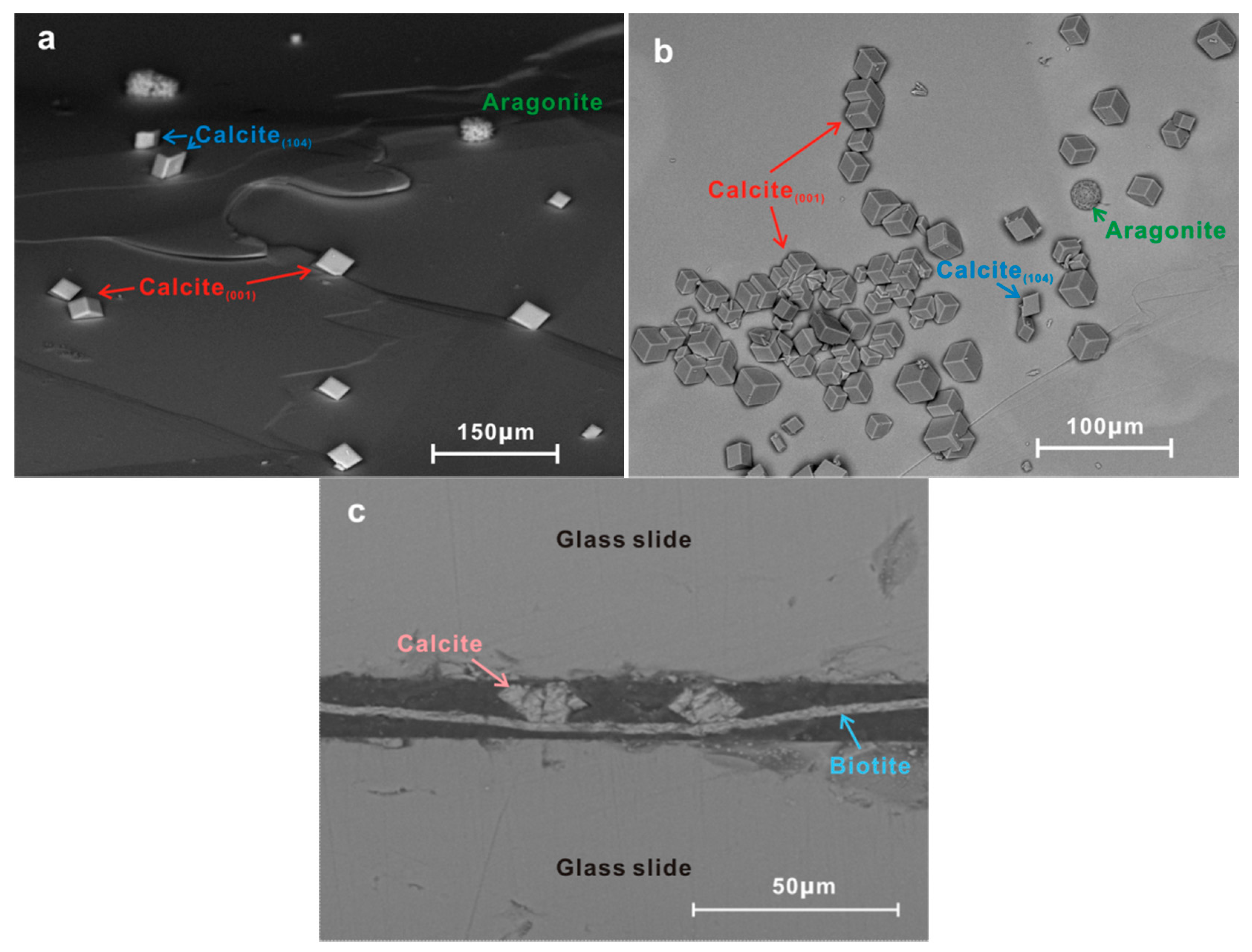
SEM studies showed densely nucleated arrays of crystals of various sizes on biotite substrates (Figure 2). EDS-derived chemical composition indicated carbonate precipitation while crystal morphology suggested the occurrence of both calcite and aragonite. XRD analysis further confirmed the presence of ~5% aragonite. Whereas calcite appeared in the usually rhombic {104} form, aragonite aggregates formed clusters (Figure 2a,b), showing an overall spherical shape and a lack of specific orientations.
Most of the calcite rhombs were oriented in the same direction relative to the biotite substrate with the three-fold c-axes perpendicular to the substrate. Based on cross-section (Figure 2c) and high-angle tilted SEM images (Figure 2a), we found the interface between epitaxial calcite and biotite substrate appears to be triangular and has a comparatively large area. A rare occurrence of a second set of crystal orientation was observed where calcite was situated directly on its {104} faces (Figure 2a,b).
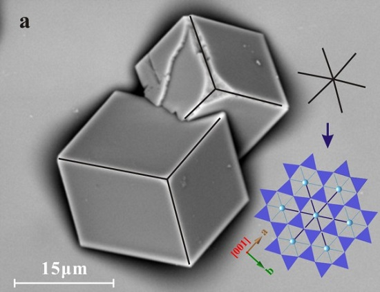
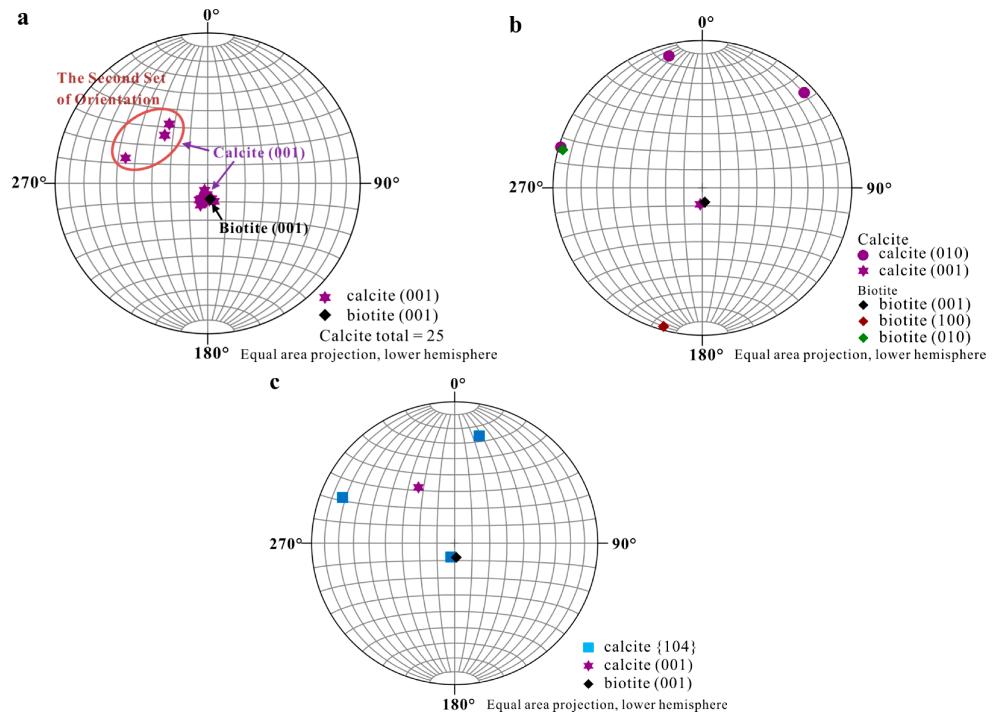
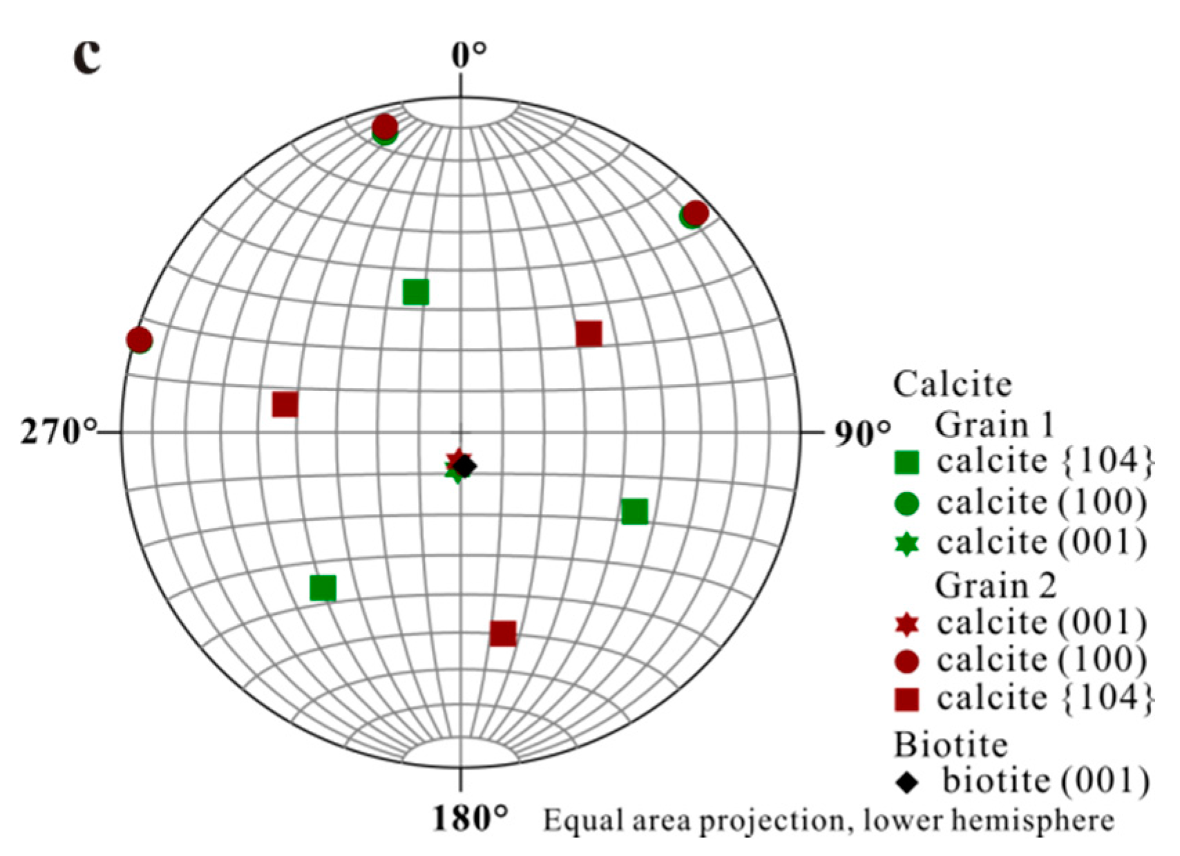
Accurate orientational information derived from EBSD analyses (Figure 3 and Figure 4) showed (1) uniform location of the calcite (001) pole for the first set of orientation (the major set), indicating orientated calcite nucleation; and (2) overlapping of the (001) poles of calcite (purple hexagons) and (001)* (i.e., normal of (001) face, black diamond) of biotite, suggesting an orientation of calcite (001) ~// biotite (001) at the interface (Figure 4). Measured orientations in 25 adjacent calcite crystals showed that 22 belonged to the first set and have a narrow distribution of angles with a spread less than 8°. Additional measurement in the major set also revealed a relation of calcite (010) ~// biotite (010) with calcite (010) pole (purple dots) overlapping with that of biotite (green square) (Figure 4b), indicating the parallel of the a-axis between calcite and biotite. For the second set of orientation, EBSD data gave a calcite {104} face ~// biotite (001) interface (Figure 4c), with the location of calcite {104} poles (blue squares) overlapping with the spot from biotite (001) (black diamond). Within the first set of calcite, orientations of some calcite rhombs showed a 180° in rotation (two-fold axis) within the (001) face, satisfying a twinning configuration. This twinning feature creates an apparent six-fold symmetry (Figure 5) resultant from a combination of the three-fold symmetry of the twinned crystals, leading to a match to the pseudo-hexagonal (001) face of biotite (Figure 5c). The twinning relationship appeared in both contacted (i.e., double crystals in which the two subunits are oriented 180° apart) and un-contacted (i.e., single crystals with a 180° rotation in their c-axis) form. The twinning relation can be better viewed on the schematic diagrams showing the orientation of the calcite twins and their relationships with reference to the biotite substrate (Figure 6).
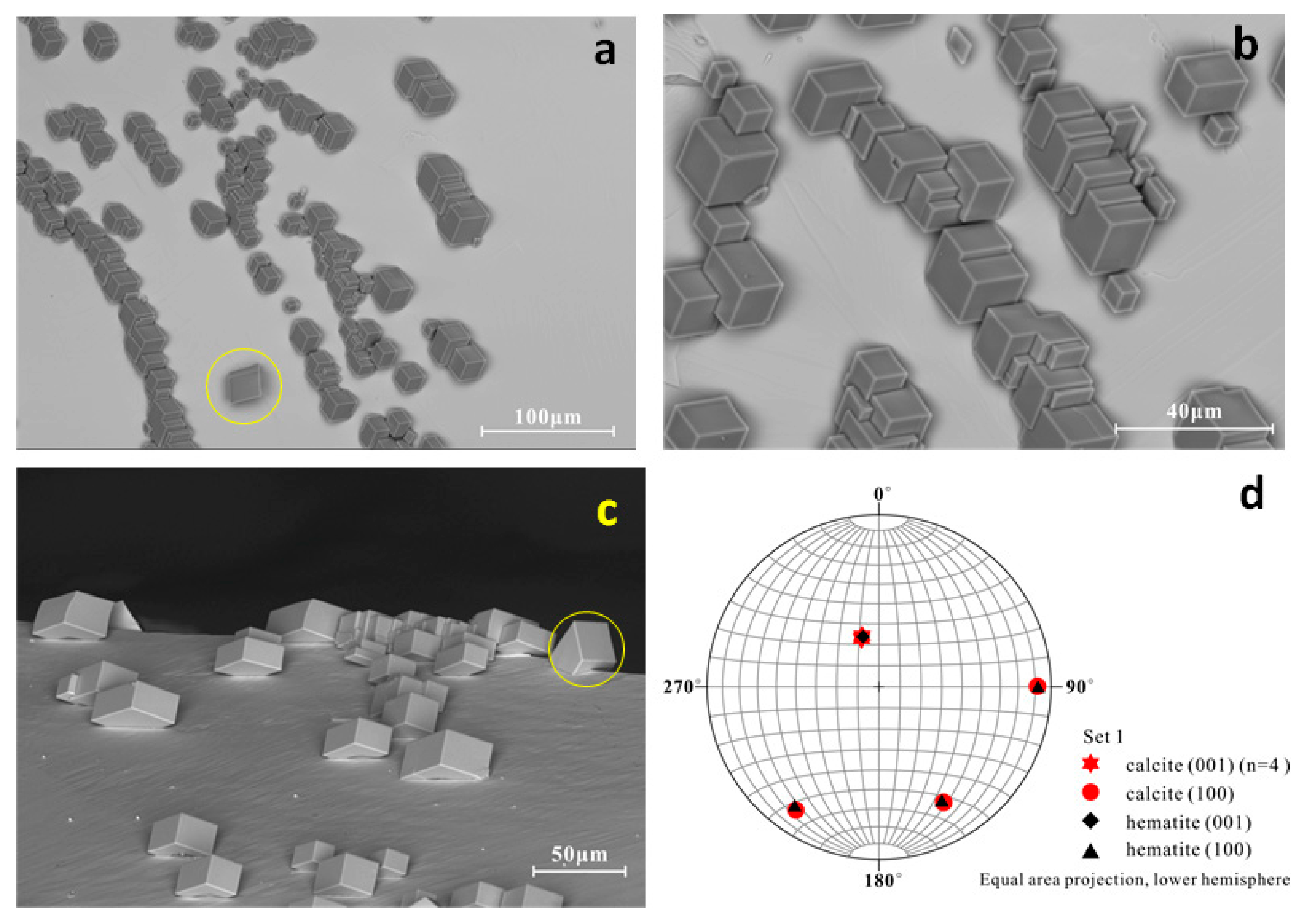
The calcite crystals grown on muscovite (001) substrate are essentially similar to those grown on biotite, except for a low population of aragonite crystals (Figure S1) coinciding with a smaller difference in lattice parameters between calcite and muscovite (Table 1). Hematite-templated calcite crystals are dominated by a single orientation (Figure 7) in light of an even smaller difference in their lattice parameters (calcite and hematite share same symmetry Rc) (Table 1). Calcite crystals on hematite rarely have twinning relationship between adjacent gains, but often showed preferential nucleation at surface steps on hematite substrate.
3.2. Influence of Mg2+ on Epitaxial Growth of Calcite
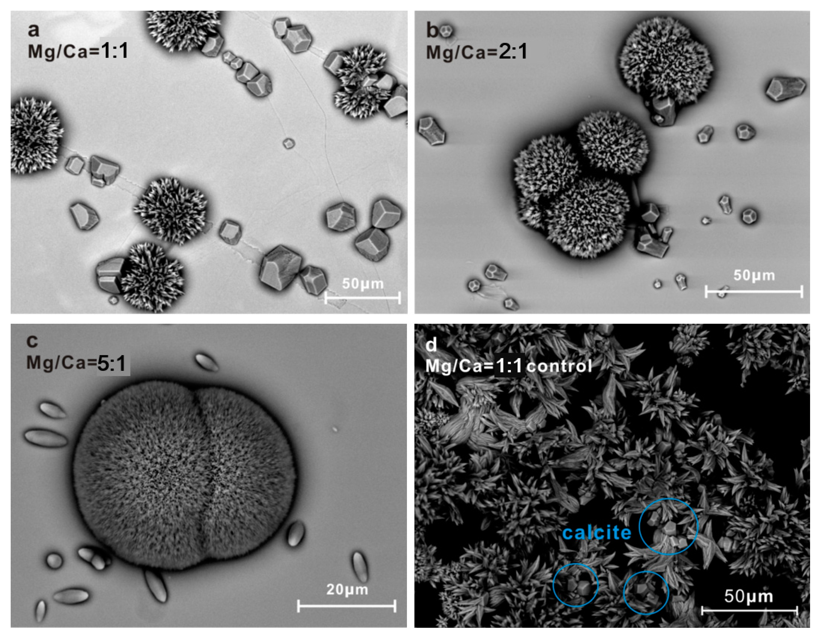
XRD pattern of control experiment (Mg/Ca = 1:1, without biotite substrate) revealed no noticeable (104) peak from calcite (i.e., less than 1%) although SEM image did show a few calcite crystals in contact with aragonite spherulites (Figure 8). Neither XRD nor SEM detected the presence of calcite when the Mg/Ca ratio was increased to 2:1. In the presence of biotite substrate, however, the crystallization system behaved noticeably differently. At Mg/Ca ratio of 1:1, calcite was clearly the dominant crystalline phase formed. Mg2+ ions did not significantly affect the preferred orientation of calcite either (Figure 8a), but did show its impact on crystal shape as the edges of the {104} rhombohedra began to disappear (Figure 8a).
A further increase in Mg2+ concentration to 2:1 resulted in significant changes on calcite morphology. In addition to the normal {104} faces, these crystals exhibited striated faces with rough texture, slightly oblique to the c-axis (Figure 8b). Morphological analyses and computer simulations showed that these new faces formed an angle of 5–14° with respect to the c-axis, which roughly corresponds to the {0k1} family of calcite, where k ranges from 1 to 3 [13]. The orientational preference of calcite was less profound, and the randomness increased as concentration of Mg increased.
Additional increase in the Mg/Ca ratio to 5:1 yielded spindle-shaped calcite crystals with uniform size, faceted only by the {0k1} surfaces [13] (Figure 8c). The crystals were elongated in the c-direction and the angle between c-axis direction and calcite crystals no longer exhibited obvious preferred orientation. Calcite was not observed when the Mg/Ca ratio increased to beyond 6:1.
Besides the change in crystal morphology, there is also a trend of decreasing crystal size from up to 20 μm in a-b dimension in the absence of Mg to needle-like crystals with {hk0} faces poorly developed when Mg/Ca ratio reached 5:1. The change in c-dimension is considerably smaller as calcite crystals can still grow up to 10 μm along c-axis in the solution with Mg/Ca ratio of 5:1. High level Mg2+ presence also appeared to lead to a more uniform crystal size distribution as the range of crystal dimensions in the a–b plane narrowed from ~5 to ~20 μm in the absence of Mg to approximately 2 μm with Mg/Ca ratio of 5:1. Large (average size ~50 μm) aragonite spherulites composed of the typical needle-shaped crystallites were found in all the solutions. The amount of aragonite crystal increases as the Mg/Ca ratio of the solutions increase (Figure 8 and Figure 9).
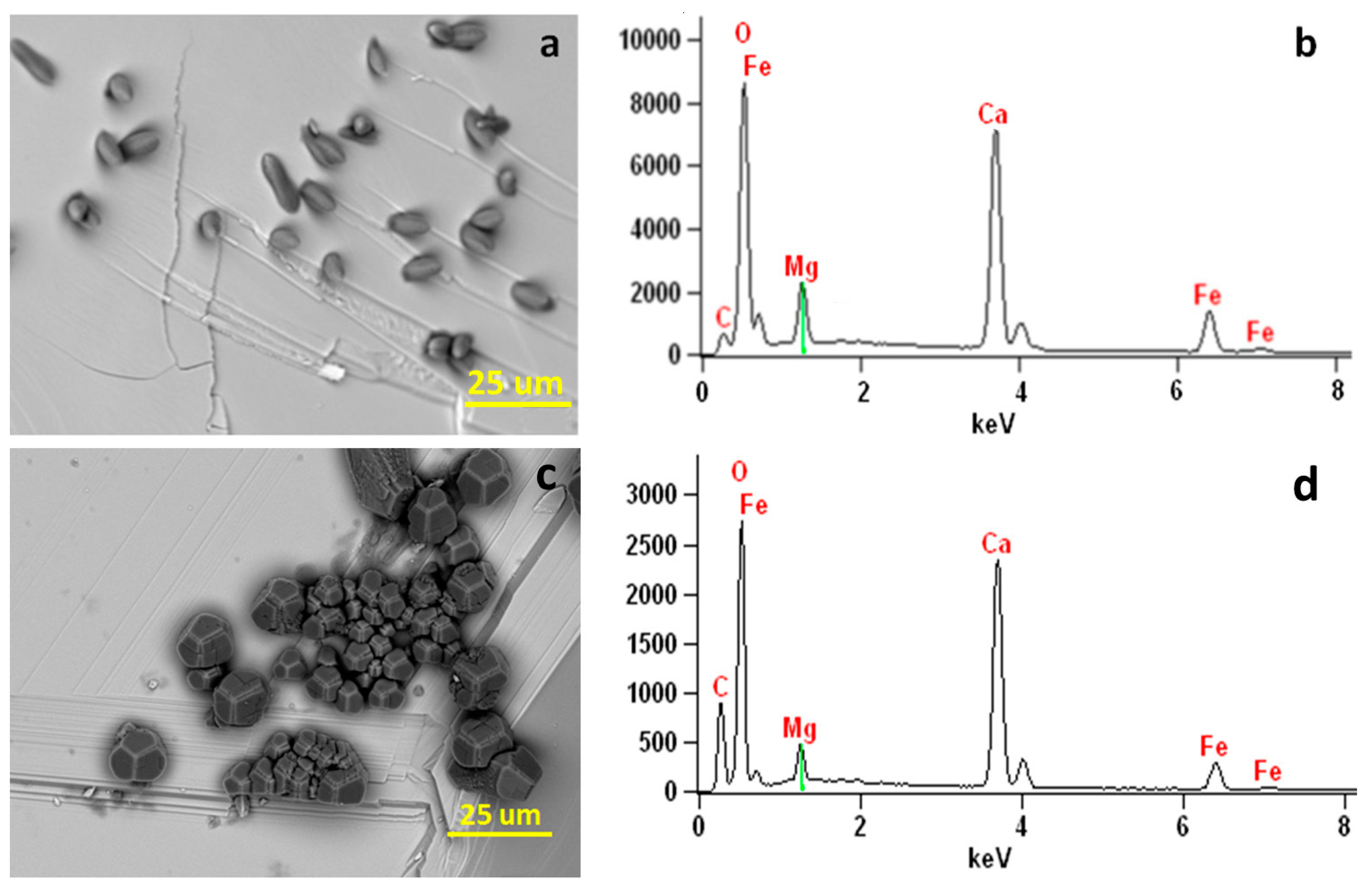
XRD patterns and the Rietveld analysis showed the percentage of calcite crystals dropped from 45% to around 2% as the Mg/Ca ratios of the solutions increased from 1:1 to 5:1 (Table 2). Furthermore, there is a significant change in the d104 values of calcite accompanied by the presence of Mg, from 3.030 (normal calcite) to 3.015 (solution Ma/Ca = 1:1), and finally to 2.998 (solution Ma/Ca ratio of 5:1) (Figure 9a). The reduction in the d104 value is presumably due to the substitution of smaller size of Mg2+ for Ca2+ leading to a shrinkage in the calcite lattice. Compositions of the precipitated crystals calculated by the empirical curve from Zhang et al. (2010) [23] using the d104 values showed that up to 19% of Mg2+ was incorporate into calcite lattice (Figure 9b, Table 2), almost doubling the reported theoretical maximum of ~10 mol % ([24,25,26]). Mg content in the calcite grown on hematite in a solution with Mg/Ca ratio of 5:1 is slightly higher (~19 mol % to ~23 mol % of MgCO3) than that on biotite (Figure 10). Mg from X-ray EDS analyses is from surface (late stage) calcite with higher Mg content. Mg content in calcite from XRD analysis indicates average composition of the Mg-bearing calcite.
4. Discussion
4.1. Calcite Growth in Mg2+-Free System
It is well known that ion exchange on biotite surface is a common occurrence. For example, it was shown that K+ can be easily replaced by ions such as H+, Mg2+, and Ca2+ [27]. Refrence [28] even reported that the process of K+ replacement by Mg2+ and Ca2+ goes to completion in a few minutes and is irreversible. We suggest this ion exchange process plays an important role in the epitaxial growth of calcite by affecting the composition of biotite surface, thus altering its overall surface behavior. Based on the results of previous studies, we deduce that K+ on biotite surface is replaced rapidly and permanently by Ca2+ once the mica is exposed to Ca2+-containing solutions. Furthermore, we believe the newly formed Ca2+ layer should be fairly stable as ion mobility measurements revealed that Mg2+ and Ca2+ move much more slower than K+ and H+ on mica surfaces [28]. Constrained by charge balance, Ca2+ should be found in part of sites previously occupied by K+. Such formed sheet of calcium is expected to attract CO32− ions from the solution and provide the epitaxial affect for subsequent carbonate nucleation.
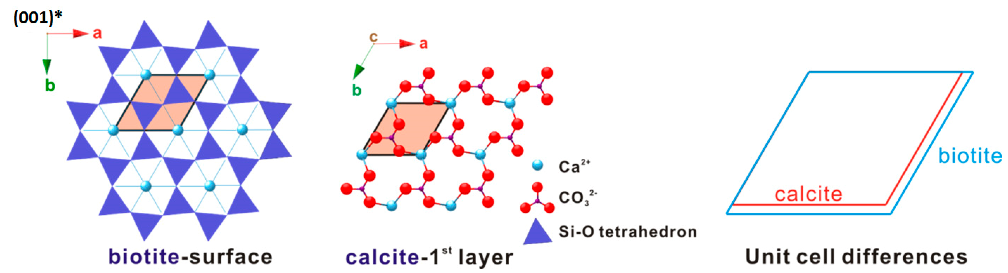
A critical requirement for epitaxy is a close match of the lattice planes between substrate and epitaxial crystals [29]. The occurrence of the calcite (001) twinning confirms (i.e., symmetry match) this view point. The first is the alignment the a-axis of biotite and the a-axis of calcite, and the other is between the [120]-direction of calcite and the b-axis of biotite. The difference within the two direction sets is +4.3% and +6.8%, respectively, resulting in a 14% overall area difference. Besides this, as far as the lattices’ geometric difference concerns, any adjacent four Ca2+ positions form a rhombus very similar to that of calcite (Figure 11) and is expected to make a minimal contribution to the overall mismatch between the subtract and the first deposited layer.
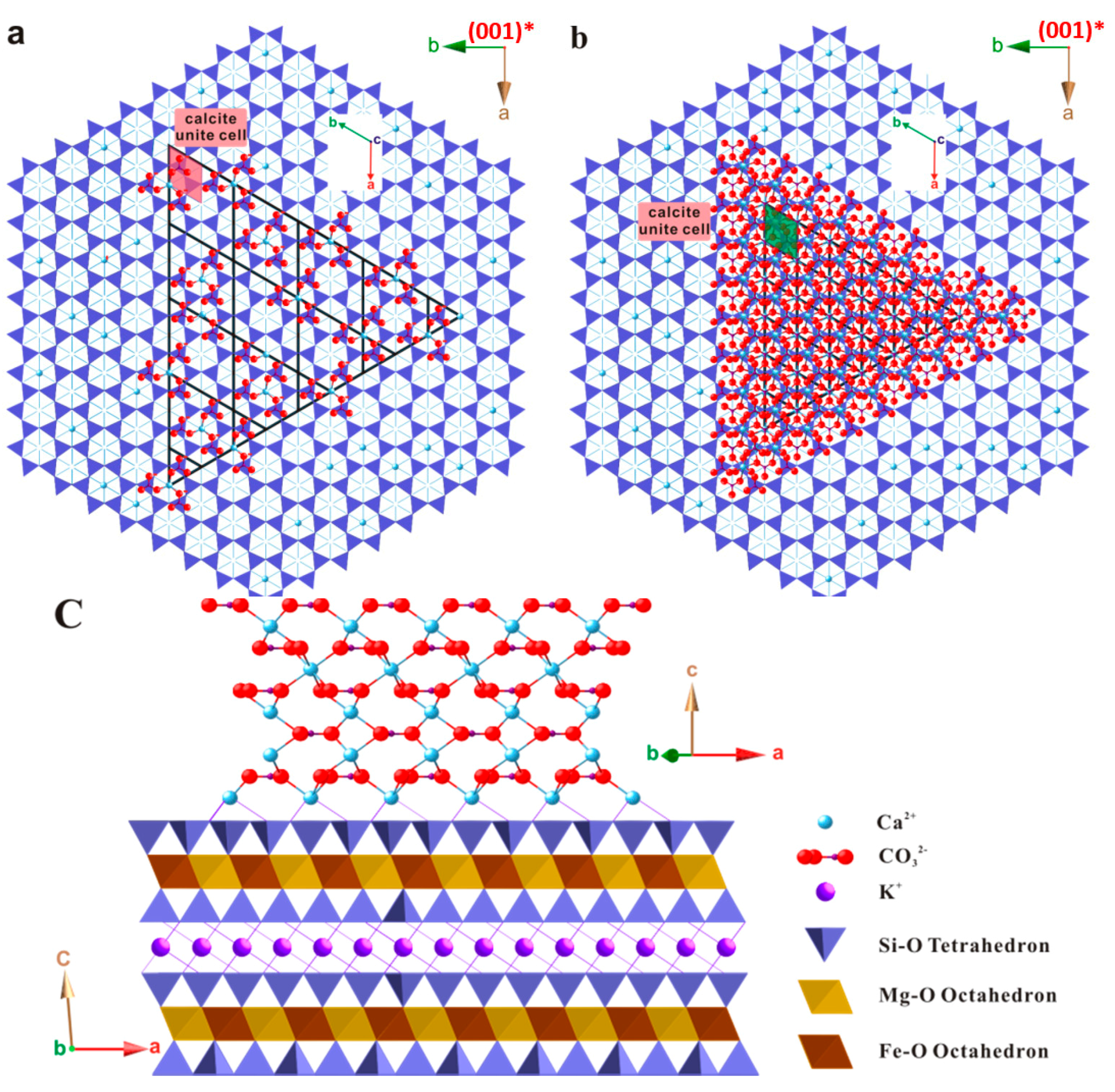
Despite the small difference, it is anticipated that strains are present in the first few layers of calcite at the interface of the substrate. The magnitude of the strain is not readily available, but is expected to be related to the substrate-calcite nuclei interaction. In the case of a strong host-guest mineral interaction, the first few layers of calcite could be deviated from ideal calcite structure. This may lead to an elongated Ca–CO3 bond and a more significant strained lattice. If the interactions are weak, the first Ca2+ layer may reorganize itself with little energy cost, so as to form arrangements which more closely resemble planes of calcite in the bulk crystal. Figure 12b–d illustrates the possible initial state of calcite growing on biotite substrate with an expected minimal mismatch. The shape of calcite-biotite interface is created as a triangle based on the interface morphology derived from SEM studies and the crystal shape of calcite.
Our observations of the first set orientation are consistent with previous work on the epitaxial growth of calcite on muscovite [14,15]. For example, the authors of reference [14] showed through their SEM and XRD measurements that the (001) plane of calcite is aligned virtually parallel to the muscovite basal plane, which is the same orientation in biotite. Although the difference in 2-D lattices between muscovite and calcite is smaller than that for biotite (Table 1), there is no significant difference in either crystal size or density between these two micas except less aragonite crystals on muscovite surface.
For the second set of calcite where the crystals sit on one of {104} faces, there is no obvious matching relation between the two lattices. We suspect this is due to damage on mica surfaces that have lost the regular pseudo-hexagonal patterns. Nucleation of calcite on such surfaces may be similar to those on glass, and is very different from those on minerals in that the formed crystals do not display preferred orientation (Figure S2). Calcite crystals grown on glass commonly nucleated on the most stable {104} faces (Figure S2), similar to what appears in homogeneous solution crystallization processes.
4.2. Calcite Growth in Ca2+-Mg2+ System
It is widely recognized that aqueous Mg2+ has a strong effect on calcium carbonate mineralization. Normally, calcite precipitates if the Mg/Ca ratio of the solution is below about 1:5 (a tenth that of normal seawater), and aragonite becomes the only polymorph if Mg/Ca ≥ 1 [30]. This is consistent with the observations in modern marine environment where dissolved magnesium appears to have no effect on the rate of crystal growth of aragonite, but has a strong inhibiting effect on the growth of calcite, the thermodynamically more stable form [25,31,32,33,34,35,36].
Our results indicate that substrate effect may alleviate the Mg inhibition on calcite crystallization as (1) calcite did not cease to precipitate until the ratio of Mg/Ca reached above 5; and (2) the Mg incorporation in calcite was higher than the reported values for Mg-bearing calcite grown in systems without substrates. We don’t have direct experimental observations to pinpoint the cause of the substrate effect, but we can explain this phenomenon by considering the interfacial adsorption of Mg ions. The calcite crystals grown on hematite (001) substrate contain more Mg that those grown on mica. Compared to Ca2+, Mg2+ is about 30% smaller in ionic radius and therefore carries as much as twice of the charge density. This leads to a stronger hydration of Mg2+ and, consequently, a higher level of difficulty for magnesium ions to adsorb onto mica surface. As a result, the initial state of substrate-promoted calcite crystallization should experience little Mg2+ influence. The preferred orientation created by biotite surface at the initial stage which aligns calcite crystals in their c-directions (i.e., a slice of pure Ca ion) may be a deciding factor that lessens the Mg retardation. However, as Mg in the solution increases, the calcite crystals lose their crystallographic orientation relationship with the substrates. It is proposed that adsorbed Mg-water complexes on the mineral substrates decrease or even eliminate the effect of pseudo-hexagonal patterns of the substrate surface on oriented nucleation of the Mg-bearing calcite crystals.
Calcite growth rates are thought to change as a function of saturation states, but, within a given saturation state, factors such as pH, ionic strength, reagent ion ratios, and incorporated impurities (Mg in here) are also important [37,38,39,40]. Non-uniform growth rate along different directions may result in crystal shapes with elongated directions. The development of elongation on calcite may indicate a selective binding of partially hydrated Mg2+ onto the {0kl} surfaces of calcite [41], which are nearly parallel to the c-axis. This direction-specific adsorption can limit the crystal growth on {hk0} faces [13], thus promoting growth in the c-direction and ultimately yielding the uniform rod-shaped crystals. The relative strong binding of Mg to the {hk0} faces reduces growth of calcite along a and b directions but with a high overall incorporation of magnesium. Our early in situ atomic force microscopy (AFM) results indicated that incorporation of Mg in the calcite results in slower growth rates along a and b directions [42]. The (104) steps look like tear-drop elongated along c-axis (traces of c-axis in here) (Figure S3). Reduced growth rates along a and b directions resulted in the observed elongated crystals (Figure S4).
5. Conclusions
Our study indicates that mica or hematite as a substrate can promote the nucleation and growth of calcium carbonate even in high-concentration Mg-bearing solutions. Based upon structure analysis, we suggest this is due to the close-match of lattices between calcite and the substrates. Specifically, the locations of the K+ sites on biotite basal surface constitute geometrical pattern that matches well with the calcite rhombus. For nucleation mechanism, we believe that the substitution and adsorption of Ca2+ on the K+ sites provides a bridge which attracts CO32− groups and acts as the precursor of calcite crystal. Lattice strain can be compensated either by slight displacement of Ca2+ layer on biotite surface or by dislocations inside calcite crystals.
On mica and hematite substrates, calcite can form in solutions with Mg/Ca ratio up to 5:1; moreover, as much as ~20% of MgCO3 can be incorporated into calcite crystals nucleated on the substrates. Our study provides baseline to further understand the templating effect of non-carbonate substrates on carbonate mineralization. The new results may provide better understanding about Ca–Mg carbonate precipitation in subsurface environment after CO2 injection. Ca-Mg-carbonates are stable phases for long-term carbon immobilization and sequestration.
Supplementary Materials
The following are available online at www.mdpi.com/2075-163X/8/1/17/s1, Figure S1: SEM image showing calcite crystals on (001) surface of a muscovite. Crystals C and C’ are in twinning relationship, Figure. S2: Calcite crystals and small amount of aragonite aggregates nucleated on gorilla glass, Figure S3: AFM images sowing (104) surface steps grown in Mg-free solution (left) and Mg-bearing solution with Mg/Ca ratio = 5/1 (right). Incorporation of Mg in the calcite results in slower growth rates along a and b directions. The (104) steps look like tear-drop elongated along c-axis (traces of c-axis in here), Figure S4: Diagrams showing the surface step and shape changes as Mg incorporated into the Mg-bearing calcite structure. Reduced growth rates along a and b directions resulted in the observed elongated crystals.
Acknowledgments
This research was funded by the Department of Energy of United States (DE-FG02-09ER16050), National Science Foundation, and NASA Astrobiology Institute (NNA13AA94A). Authors thank two anonymous reviewers for their constructive suggestions.
Author Contributions
Huifang Xu and H. Henry Teng conceived the idea; Huifang Xu and Mo Zhou designed the experiments; Mo Zhou and Huifang Xu performed the experiments; Huifang Xu, Mo Zhou, and Yihang Fang analyzed the data. All the authors contributed to manuscript writing.
Conflicts of Interest
The authors declare no conflict of interest.
References
- Conti, J.J.; Holtberg, P.D.; Beamon, J.A.; Schaal, A.M.; Ayoub, J.C.; Turnure, J.T. Annual energy outlook 2011: With Projections to 2035. 2011. Available online: https://www.eia.gov/outlooks/archive/aeo11/pdf/0383(2011).pdf (accessed on 10 September 2012).
- Mani, D.; Charan, S.N.; Kumar, B. Assessment of carbon dioxide sequestration potential of ultramafic rocks in the greenstone belts of southern India. Curr. Sci. 2008, 94, 53–61. [Google Scholar]
- Conwa, T.; Tans, P. Trends in Atmospheric Carbon Dioxide. Available online: https://www.esrl.noaa.gov/gmd/ccgg/trends/ (accessed on 1 September 2017).
- Stern, N.H. Executive review. In The Economics of Climate Change: The Stern Review; Cambridge University Press: Cambridge, UK, 2007; ISBN 0521700809. [Google Scholar]
- Benson, L. Carbonate deposition, Pyramid Lake subbasin, Nevada: 1. Sequence of formation and elevational distribution of carbonate deposits (Tufas). Palaeogeogr. Palaeoclimatol. Palaeoecol. 1994, 109, 55–87. [Google Scholar] [CrossRef]
- Ryu, K.W.; Lee, M.G.; Jang, Y.N. Mechanism of tremolite carbonation. Appl. Geochem. 2011, 26, 1215–1221. [Google Scholar] [CrossRef]
- Goff, F.; Lackner, K.S. Carbon dioxide sequestering using ultramafic rocks. Environ. Geosci. 1998, 5, 89–101. [Google Scholar]
- Koustoukos, P.G.; Nancollas, G.H. Crystal growth of calcium phosphates - epitaxial considerations. J. Cryst. Growth 1981, 53, 10–19. [Google Scholar]
- Belcher, A.M.; Wu, X.H.; Christensen, R.J.; Hansma, P.K.; Stucky, G.D.; Morse, D.E. Control of crystal phase switching and orientation by soluble mollusc-shell proteins. Nature 1996, 381, 56–58. [Google Scholar] [CrossRef]
- DeOliveira, D.B.; Laursen, R.A. Control of Calcite Crystal Morphology by a Peptide Designed To Bind to a Specific Surface. J. Am. Chem. Soc. 1997, 119, 10627–10631. [Google Scholar] [CrossRef]
- Aizenberg, J.; Black, A.J.; Whitesides, G.M. Control of crystal nucleation by patterned self-assembled monolayers. Nature 1999, 398, 495–498. [Google Scholar]
- Travaille, A.M.; Donners, J.J.J.M.; Gerritsen, J.W.; Sommerdijk, N.A.J.M.; Nolte, R.J.M.; van Kempen, H. Aligned Growth of Calcite Crystals on a Self-Assembled Monolayer. Adv. Mater. 2002, 14, 492–495. [Google Scholar]
- Han, Y.; Aizenberg, J. Effect of Magnesium Ions on Oriented Growth of Calcite on Carboxylic Acid Functionalized Self-Assembled Monolayer. J. Am. Chem. Soc. 2003, 125, 4032–4033. [Google Scholar] [CrossRef] [PubMed]
- Stephens, C.J.; Mouhamad, Y.; Meldrum, F.C.; Christenson, H.K. Epitaxy of Calcite on Mica. Cryst. Growth Des. 2010, 10, 734–738. [Google Scholar] [CrossRef]
- Yamanaka, S.; Ito, N.; Shimosaka, A.; Shirakawa, Y.; Hidaka, J. AFM Investigation for the initial growth processes of calcium carbonate on hydrophilic and hhydrophobic substrate. Cryst. Growth Des. 2009, 9, 3245–3250. [Google Scholar] [CrossRef]
- Shelobolina, E.; Xu, H.; Konishi, H.; Kukkadapu, R.; Wu, T.; Blöthe, M.; Roden, E. Microbial Lithotrophic Oxidation of Structural Fe(II) in Biotite. Appl. Environ. Microbiol. 2012, 78, 5746–5752. [Google Scholar] [CrossRef] [PubMed]
- Addadi, L.; Moradian, J.; Shay, E.; Maroudas, N.G.; Weiner, S. A chemical model for the cooperation of sulfates and carboxylates in calcite crystal nucleation: Relevance to biomineralization. Proc. Natl. Acad. Sci. USA 1987, 84, 2732–2736. [Google Scholar] [CrossRef] [PubMed]
- Aizenberg, J.; Albeck, S.; Weiner, S.; Addadi, L. Crystal—Protein interactions studied by overgrowth of calcite on biogenic skeletal elements. J. Cryst. Growth 1994, 142, 156–164. [Google Scholar] [CrossRef]
- Paquette, J.; Reeder, R.J. Relationship between surface structure, growth mechanism, and trace element incorporation in calcite. Geochim. Cosmochim. Acta 1995, 59, 735–749. [Google Scholar] [CrossRef]
- Jiménez-López, C.; Caballero, E.; Huertas, F.J.; Romanek, C.S. Chemical, mineralogical and isotope behavior, and phase transformation during the precipitation of calcium carbonate minerals from intermediate ionic solution at 25 °C. Geochim. Cosmochim. Acta 2001, 65, 3219–3231. [Google Scholar] [CrossRef]
- Becker, A.; Becker, W.; Marxen, J.C.; Epple, M. In-vitro Crystallization of Calcium Carbonate in the Presence of Biological Additives—Comparison of the Ammonium Carbonate Method with Double-Diffusion Techniques. Z. Anorg. Allg. Chem. 2003, 629, 2305–2311. [Google Scholar] [CrossRef]
- Gruzensky, P.M. Growth of calcite crystals. J. Phys. Chem. Solids 1967, 365–367. [Google Scholar]
- Zhang, F.; Xu, H.; Konishi, H.; Roden, E.E. A relationship between d104 value and composition in the calcite-disordered dolomite solid-solution series. Am. Mineral. 2010, 95, 1650–1656. [Google Scholar] [CrossRef]
- Chave, K.E.; Deffeyes, K.S.; Weyl, P.K.; Garrels, R.M.; Thompson, M.E. Observations on the solubility of skeletal carbonates in aqueous solutions. Science 1962, 137, 33–34. [Google Scholar] [CrossRef] [PubMed]
- Berner, R.A. The role of magnesium in the crystal growth of calcite and aragonite from sea water. Geochim. Cosmochim. Acta 1975, 39, 489–494. [Google Scholar] [CrossRef]
- Walter, L.M.; Hanor, S. Effect of orthophosphate on the dissolution kinetics of biogenic magnesian calcites. Geochim. Cosmochim. Acta 1979, 43, 1377–1385. [Google Scholar] [CrossRef]
- Christenson, H.K. Adhesion and surface energy of mica in air and water. J. Phys. Chem. 1993, 97, 12034–12041. [Google Scholar] [CrossRef]
- Xu, L.; Salmeron, M. Effects of surface ions on the friction and adhesion properties of mica. Langmuir 1998, 14, 2187–2190. [Google Scholar] [CrossRef]
- Shtukenberg, A.G.; Popov, D.Y.; Punin, Y.O. Growth ordering and anomalous birefringence in ugrandite garnets. Mineral. Mag. 2005, 69, 537–550. [Google Scholar] [CrossRef]
- Morse, J.W.; Wang, Q.; Tsio, M.Y. Influences of temperature and Mg:Ca ratio on CaCO3 precipitates from seawater. Geology 1997, 25, 85–87. [Google Scholar] [CrossRef]
- Reddy, M.M.; Nancollas, G.H. The crystallization of calcium carbonate. IV. The effect of magnesium, strontium and sulfate ions. J. Cryst. Growth 1976, 35, 33–38. [Google Scholar] [CrossRef]
- Reddy, M.M.; Wang, K.K. Crystallization of calcium carbonate in the presence of metal ions. I. Inhibition by magnesium ions at pH 8.8 and 25 °C. J. Cryst. Growth 1980, 50, 470–480. [Google Scholar] [CrossRef]
- Falini, G.; Gazzano, M.; Ripamonti, A. Crystallization of calcium carbonate in presence of magnesium and polyelectrolytes. J. Cryst. Growth 1994, 137, 577–584. [Google Scholar] [CrossRef]
- Fernandez-Diaz, L.; Putnis, A.; Prieto, M.; Putnis, C.V. The role of magnesium in the crystallization of calcite and aragonite in a porous medium. J. Sediment. Res. 1996, 66, 482–491. [Google Scholar]
- Chen, T.; Neville, A.; Yuan, M. Influence of Mg2+ on CaCO3 formation—Bulk precipitation and surface deposition. Chem. Eng. Sci. 2006, 61, 5318–5327. [Google Scholar] [CrossRef]
- Astilleros, J.M.; Fernandez-Diaz, L.; Putnis, A. The role of magnesium in the growth of calcite: An AFM study. Chem. Geol. 2010, 271, 52–58. [Google Scholar] [CrossRef] [Green Version]
- Teng, H.H.; Dove, P.M.; De Yoreo, J.J. Kinetics of calcite growth: Surface processes and relationships to macroscopic rate laws. Geochim. Cosmochim. Acta 2000, 64, 2255–2266. [Google Scholar] [CrossRef]
- Hong, M.; Teng, H.H. Implications of solution chemistry effects: Direction-specific restraints on the step kinetics of calcite growth. Geochim. Cosmochim. Acta 2014, 141, 228–239. [Google Scholar] [CrossRef]
- Van Der Weijden, C.H.; Van Der Weijden, R.D. Calcite growth: Rate dependence on saturation, on ratios of dissolved calcium and (bi)carbonate and on their complexes. J. Cryst. Growth 2014, 394, 137–144. [Google Scholar] [CrossRef]
- Sand, K.K.; Tobler, D.J.; Dobberschütz, S.; Larsen, K.K.; Makovicky, E.; Andersson, M.P.; Wolthers, M.; Stipp, S.L.S. Calcite Growth Kinetics: Dependence on Saturation Index, Ca2+:CO32− Activity Ratio, and Surface Atomic Structure. Cryst. Growth Des. 2016, 16, 3602–3612. [Google Scholar] [CrossRef]
- Raz, S.; Weiner, S.; Addadi, L. Formation of high-magnesian calcites via an amorphous precursor phase: Possible biological implications. Adv. Mater. 2000, 12, 38–42. [Google Scholar] [CrossRef]
- Zhang, F.; Yan, C.; Teng, H.H.; Roden, E.E.; Xu, H. In situ AFM observations of Ca-Mg carbonate crystallization catalyzed by dissolved sulfide: Implications for sedimentary dolomite formation. Geochim. Cosmochim. Acta 2013, 105, 44–55. [Google Scholar] [CrossRef]
Figure 1.
Illustration diagram of free-drift experiment.

Figure 2.
SEM images of calcium carbonate crystals on biotite substrate. (a) High-angle tilted conditions showing the interfaces between calcite crystals and substrate with (001) surface steps; (b) Regular SEM image shows the calcite crystals on biotite. Two sets of oriented calcite crystals and aragonite aggregates are indicated in both images; (c) Cross-section SEM image of two calcite crystals on biotite substrate. The dark bands above and below the biotite are epoxy.

Figure 3.
Typical Kikuchi patterns of biotite substrate (a) and calcite (b) which has calcite (001) ~// biotite (001).
Figure 3.
Typical Kikuchi patterns of biotite substrate (a) and calcite (b) which has calcite (001) ~// biotite (001).

Figure 4.
Stereographic Projection of calcite crystals on biotite substrate. (a) Overall stereographic projection of calcite crystals and biotite substrate which shows two sets of orientation; (b) Stereographic projection from first set of calcite indicating calcite (001) ~// biotite (001) and calcite (010) ~// biotite (010); (c) Stereographic projection from second set of calcite with a calcite {104} face ~// biotite (001).

Figure 5.
SEM images and stereographic projection of calcite (001) twinning explaining the six-fold symmetry created. (a) A contact calcite (001) twin SEM image showing the overall six-fold symmetry which matches the biotite’s pseudo-hexagonal on the right; (b) High-angle SEM image of un-contact calcite crystals in (001) twinning relationship; (c) Stereographic projection of calcite (001) twin with (001) of both crystals overlap with biotite (001), and two sets of {104} faces forming the six-fold symmetry.


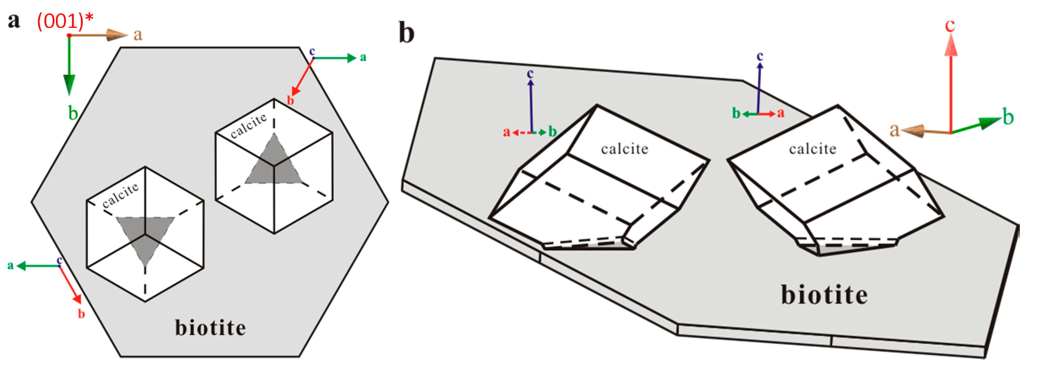
Figure 6.
Figures demonstrating the calcite twinning on biotite substrate. (a) Top view; (b) Side view.
Figure 6.
Figures demonstrating the calcite twinning on biotite substrate. (a) Top view; (b) Side view.

Figure 7.
SEM images ((a,b) top view; (c) side view) and stereonet projection (d) showing calcite crystals and hematite substrate relationship. Majority of the crystals keep the same orientation with the hematite substrate. Very few crystals (circled with yellow circles) do not.
Figure 7.
SEM images ((a,b) top view; (c) side view) and stereonet projection (d) showing calcite crystals and hematite substrate relationship. Majority of the crystals keep the same orientation with the hematite substrate. Very few crystals (circled with yellow circles) do not.

Figure 8.
Morphologies of calcite crystals precipitated from solutions of different Mg/Ca ratios. (a) SEM image of calcite and aragonite on the biotite substrate. The mole ratio of Mg/Ca in solution is 1:1. Calcite occurs as isolated crystals, whereas aragonite occurs as spherical aggregates; (b) SEM image of calcite and aragonite on the biotite substrate. The mole ratio of Mg/Ca in solution is 2:1; (c) SEM image of Mg-bearing calcite (elongated oval shapes) and aragonite aggregate on the biotite substrate. The mole ratio of Mg/Ca in solution is 5:1; (d) Control experiment with Mg/Ca ratio of 1:1 mole in solution showing very small amount of calcite crystals (under 1%).

Figure 9.
(a) XRD patterns and d104 values of magnesian-calcite precipitated from solutions of different Mg/Ca ratios. (b) Relationship between the relative rate of calcite and aragonite precipitation and Mg incorporation in the calcite.
Figure 9.
(a) XRD patterns and d104 values of magnesian-calcite precipitated from solutions of different Mg/Ca ratios. (b) Relationship between the relative rate of calcite and aragonite precipitation and Mg incorporation in the calcite.

Figure 10.
(a) SEM image showing elongated Mg-bearing calcite crystals on (001) surface of the hematite substrate in a solution with Mg:Ca ratio of 5:1. (b) X-ray EDS spectrum showing Mg (~21 mol % of MgCO3) in the Mg-bearing calcite crystals. (c) SEM image showing elongated Mg-bearing calcite crystals on (001) surface of the hematite substrate in a solution with Mg:Ca ratio of 2:1. (d) X-ray EDS spectrum showing Mg (~10 mol % of MgCO3) in the Mg-bearing calcite crystals. Fe peaks are from the hematite substrate.

Figure 11.
Two-dimensional (2-D) lattice difference between biotite and calcite.

Figure 12.
Various stages of calcite overgrowing on biotite substrate of both horizontal and vertical views. (a) First layer of calcite Ca2− and CO32− on biotite substrate; (b) Three layers of calcite Ca2+ and CO32− on biotite substrate; (c) Side view of five layers of calcite Ca2+ and CO32− on biotite.


Table 1.
Difference between calcite and its substrates of biotite, muscovite, and hematite.
| Difference Values for Biotite and Muscovite | |||||
|---|---|---|---|---|---|
| Substrate | a-Axis (Å) | b-Axis (Å) | Angle (°) | Δ Area (Å2) | Overall |
| Biotite | 0.348 | 0.57 | 0 | 6.3% | 14% |
| Muscovite | 0.201 | 0.40 | 0 | 4.0% | 9% |
| Hematite | 0.050 | 0.07 | 0 | 1.0% | 2% |
Notes: Overall difference % = 100% × {(Δa)2 + (Δb)2 + |Δarea|}/{(acc)2 + (bcc)2 + |areacc|}. Δa: difference between certain configuration’s a-axis and calcite a-axis. Δb: difference between certain configuration’s b-axis and calcite b-axis. Δ area: difference between certain configuration’s areas based on orthorhombic cells. Unit cell parameters of calcite and the substrates: Calcite: a = b = 4.99 Å (or, b = 8.66 Å for orthorhombic cell); Hematite: a = b = 5.04 Å (or, b ~ 8.73 Å for orthorhombic cell); Muscovite: a = 5.209 Å, b = 9.052 Å, c = 20.125 Å, β = 95.70°; Biotite: a = 5.337 Å, b = 9.234 Å, c = 10.191 Å, β = 100.2°.
Table 2.
Relative amounts (wt %) of calcite and aragonite precipitates on the biotite and Mg contents (mol %) in calcites precipitated from various solutions with Mg/Ca ratios.
Table 2.
Relative amounts (wt %) of calcite and aragonite precipitates on the biotite and Mg contents (mol %) in calcites precipitated from various solutions with Mg/Ca ratios.
| Mg/Ca Ratio | Calcite % (±1%) | MgCO3 % (±2%) |
|---|---|---|
| 0 | 95.0% | 0% |
| 1 | 45.1% | 5.2% |
| 2 | 10.9% | 8.4% |
| 5 | 2.4% | 18.7% |
| 6 | 0.0% | N/A |
© 2018 by the authors. Licensee MDPI, Basel, Switzerland. This article is an open access article distributed under the terms and conditions of the Creative Commons Attribution (CC BY) license (http://creativecommons.org/licenses/by/4.0/).
Share and Cite
MDPI and ACS Style
Xu, H.; Zhou, M.; Fang, Y.; Teng, H.H. Effect of Mica and Hematite (001) Surfaces on the Precipitation of Calcite. Minerals 2018, 8, 17. https://doi.org/10.3390/min8010017
AMA Style
Xu H, Zhou M, Fang Y, Teng HH. Effect of Mica and Hematite (001) Surfaces on the Precipitation of Calcite. Minerals. 2018; 8(1):17. https://doi.org/10.3390/min8010017
Chicago/Turabian StyleXu, Huifang, Mo Zhou, Yihang Fang, and H. Henry Teng. 2018. "Effect of Mica and Hematite (001) Surfaces on the Precipitation of Calcite" Minerals 8, no. 1: 17. https://doi.org/10.3390/min8010017
Note that from the first issue of 2016, this journal uses article numbers instead of page numbers. See further details here.