Communication

Influence of Slip and Lubrication Regime on the Formation of White Etching Cracks on a Two-Disc Test Rig †

by
Francisco Gutiérrez Guzmán
1,*,
Mehmet Ozan Oezel
2,
Georg Jacobs
1,
Gero Burghardt
1,
Christoph Broeckmann
2 and
Thomas Janitzky
2
1
Institute for Machine Elements and Machine Design, RWTH Aachen University, Schinkelstrasse 10, 52062 Aachen, Germany
2
Institute for Materials Applications in Mechanical Engineering, RWTH Aachen University, Augustinerbach 4, 52062 Aachen, Germany
*
Author to whom correspondence should be addressed.
This paper is a revised version of a paper published in World Tribology Congress 2017, Beijing, China, 17–22 September 2017.
Lubricants 2018, 6(1), 8; https://doi.org/10.3390/lubricants6010008
Submission received: 4 December 2017 / Revised: 2 January 2018 / Accepted: 10 January 2018 / Published: 12 January 2018
(This article belongs to the Special Issue Tribology of Machine Elements--Smart Lubricants)

Abstract

:
A common cause for maintenance and downtime in multiple fields of the mechanical transmission industries are premature rolling bearing failures due to white etching cracks (WEC). Within this work, WEC have been successfully recreated on a two-disc test rig under rolling contact loading without additional loading such as hydrogen pre-charging. This paper summarizes the state of the investigations regarding the influence of the slip type and the lubrication regime on the WEC formation on the two-disc test rig.

1. Introduction

A common challenge in multiple fields of the mechanical driveline technology consist of premature rolling bearing failures caused by white etching cracks (WEC). This failure mode can lead to bearing failure at 5–20% of the nominal life [1]. This damage pattern is characterized by sub-surface crack networks within regions of altered microstructure, which ultimately lead to axial cracking or spalling of the bearing’s raceway. These altered regions are resistant to etching and are called white etching areas (WEA) due to their white appearance under reflected light.
Although the WEA had been well characterized by different microscopy techniques [2,3], the relevant drivers and formation mechanisms are still under debate. Some authors propose that the cracks are the precursor of the WEA [4,5], while other authors have suggested that the crack initiation and propagations is a consequence of the formation of WEA [6,7]. Besides a local hydrogen ingress [1] other WEC influence factors such as lubricant composition [1,8], sliding conditions [1,9,10], tensile stresses [1,5] and electrical effects [11] had been proposed.
In a previous study, WEC tests were carried out using cylindrical roller thrust bearings. Through ultrasonic analysis on the bearing’s washers, it was shown that the WEC are mainly located in the region under negative slip [12]. However, through testing on a component level, it is not possible to decouple and assess the influence of single contact parameters, such as the slide roll ratio (SRR). Therefore, the main tribological conditions had been transferred onto a two-disc test rig using inner rings from radial cylinder roller bearings made of martensitic hardened 100Cr6 (1.3505/SAE 52100) steel. This has allowed recreation of WEC on a two-disc test rig under rolling contact loading without additional loading such as hydrogen pre-charging or passage of electrical current.
This paper summarizes the state of the investigations regarding the influence of the lubrication regime and slip on the WEC formation on the two-disc test rig.

2. Materials and Methods

2.1. Lubricant

In this study, a mineral oil with a viscosity grade of ISO VG 100—kinematic viscosity of 103.78 mm2/s at 40 °C—was used. This lubricant has led in previous studies to WEC formation in a reproducible manner [12]. Table 1 shows the results of the elemental composition analysis. The specific chemical components of this off-the-shelf fully formulated gearbox oil are not publically available.

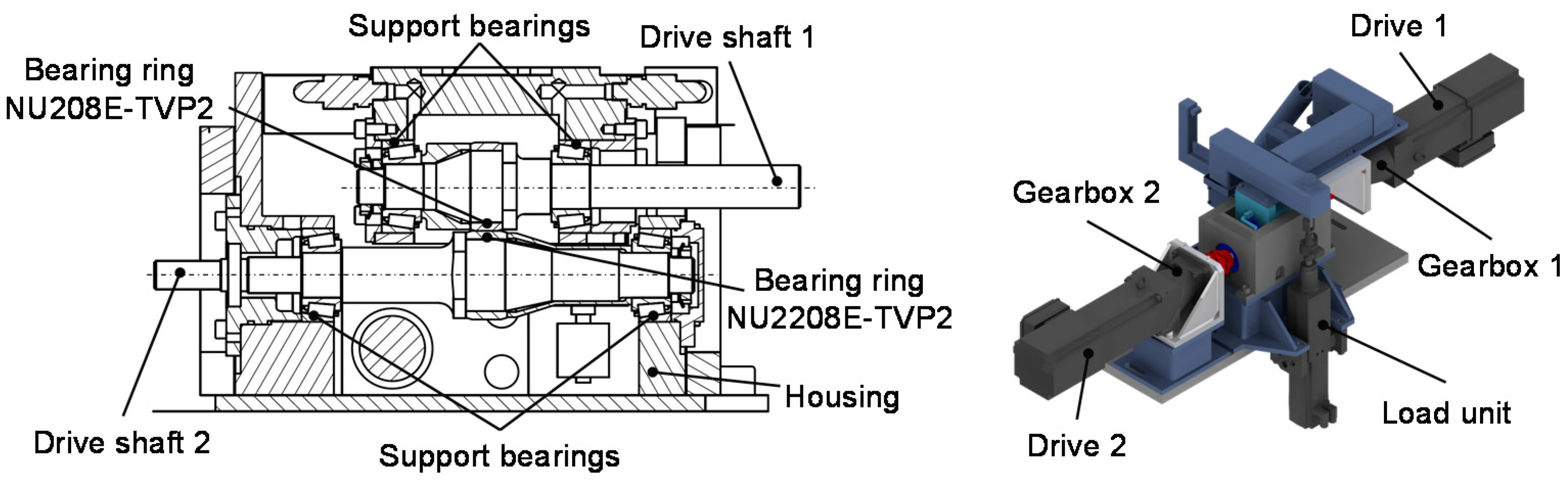
2.2. Two-Disc Test Rig

The rolling contact tests were performed on a self-developed two-disc test rig (Figure 1). Two inner rings from radial cylinder roller bearings of type NU208-TVP2 and NU2208-TVP2 are used as test specimens. The bearings rings are made from martensitic hardened 100Cr6 steel—conform to the DIN EN ISO 683-17 requirements—and are powered by independent servomotors. The freely adjustable SRRs are set by varying the speed ratio of the drive units. The variable static load is applied using a loading lever connected to the upper shaft and an electrical motor with integrated spindle. The lubrication of the test specimens and the support bearings is carried out by a circulating immersion lubrication system. The oil temperature can be adjusted using an electric heater. Testing is carried out until either a predefined number of contact load cycles is reached or a vibration level, normally caused by pitting or spalling, surpasses a set threshold.

2.3. Calculation Methods

In this work, the specific lubrication film thickness λ is used as a quantitative indicator of the lubricating conditions, which prevails in the point of contact. The λ-value, defined in Equation (1), is determined using the lubrication film thickness hmin—according to Dowson and Higginson [13]—and the measured surface roughness Ra,1 and Ra,2.
λ = h min R a , 1 2 + R a , 2 2
According to [7], values of λ ≥ 3 indicate full fluid lubrication conditions and values of λ ≤ 1 indicate boundary lubrication conditions.
Furthermore, it has been proved that the rolling contact fatigue (RCF) is strongly influenced by the presence of sliding [14,15]. The slide roll ratio, defined in Equation (2), is commonly used as a criterion to describe the ratio of the sliding ( U s l i d i n g ) and the rolling velocity ( U r o l l i n g ) in mating surfaces.
SRR = 2 ( U 1 U 2 U 1 + U 2 ) 100 %
Aside from conditions under pure rolling (0% SRR) a tangential traction force, caused by the sliding friction, is transmitted between the contact surfaces. It has been proved that the RCF is influenced by both the magnitude and the direction of the tangential traction force [16]. While the contact surface, which is running with the lower surface velocity—i.e., “follower”—experiences a traction force vector in the direction of the surface motion vector, the contact body with the higher surface velocity—i.e., “driver”—experiences a traction force vector opposed to the direction of the surface motion vector. Previous literature [15,16,17] have used the terms negative slip (follower) and positive slip (driver) to describe these contact states (Figure 2).

2.4. Test Methods

In the framework of this study, nine tests (Table 2) were carried out in order to investigate the influence of the lubrication regime and SRR on the WEC formation.
Two different test series were defined on the basis of previous investigations on two- and four-disc test rigs [7,9,10,18]. Whereas for the first test series λ-values > 3 were chosen, the second test series was conducted under boundary lubrication (λ < 1).
The selection of five different SRRs (0%, 8.3%, 12.7%, 15.0% and 21.0–23.5%) is based on previously published work [12], in which the reproducibility of WEC induced failures was demonstrated, using two cylindrical roller thrust bearings of type 81212. The contact line of this bearing type is characterized by a SSR, which increases in proportion to the distance from the center of the raceway (0% SRR) and therefore, achieves it maximum (12% SRR) at the outermost point of the contact line.
In addition to the SRRs, resulting from the axial thrust bearing’s kinematics, it has been proposed that transient events in wind turbine gearboxes—an industry sector affected by WEC—can lead to SRRs from up to 110% [1]. Therefore, tests 6, 8 and 9 were designed to simulate these conditions and were conducted with a higher SRR.
Alongside these influence factors, the kinematics of the two-disc test rig allow the assessment of the influence of the slip type on each test simultaneously. While the bearing ring NU208 runs under negative slip (follower), the bearing ring NU2208 runs under positive slip (driver).

3. Results

3.1. Influence of Sliding under Full Fluid Lubrication

The results of the first four tests are shown in Table 3. These tests were stopped after 40 × 106 cycles and showed no macroscopic signs of surface damage. Metallographic inspections conducted on both rings of test 1 and 2 and the driver of test 4 showed no WEC.

3.2. Influence of Sliding under Boundary Lubrication

The results of the second test series is shown in Table 4. Aside from test 5, which was stopped after 12 × 106, all tests where concluded when a spall failure occurred.
Within these tests, four followers (NU208) and one driver (NU2208) showed spalling. The development of surface spalling can be observed exemplary in (Figure 3). As RCF proceeds, a cluster of micro-cracks is formed, which ultimately leads to spalling of material. In contrast, the driver from test 6 showed axial cracks.
Optical metallography and SEM examinations proved that the specimens from test 6, 7, 8, 9 and 10 which experienced negative slip and the ring from test 9 which experienced positive slip, failed due to extensive white etching cracks. Although the ring from test 6, which experienced positive slip and failed due to axial cracks, was extensively serial sectioned, WEC were only found isolated and unconnected to the axial crack.

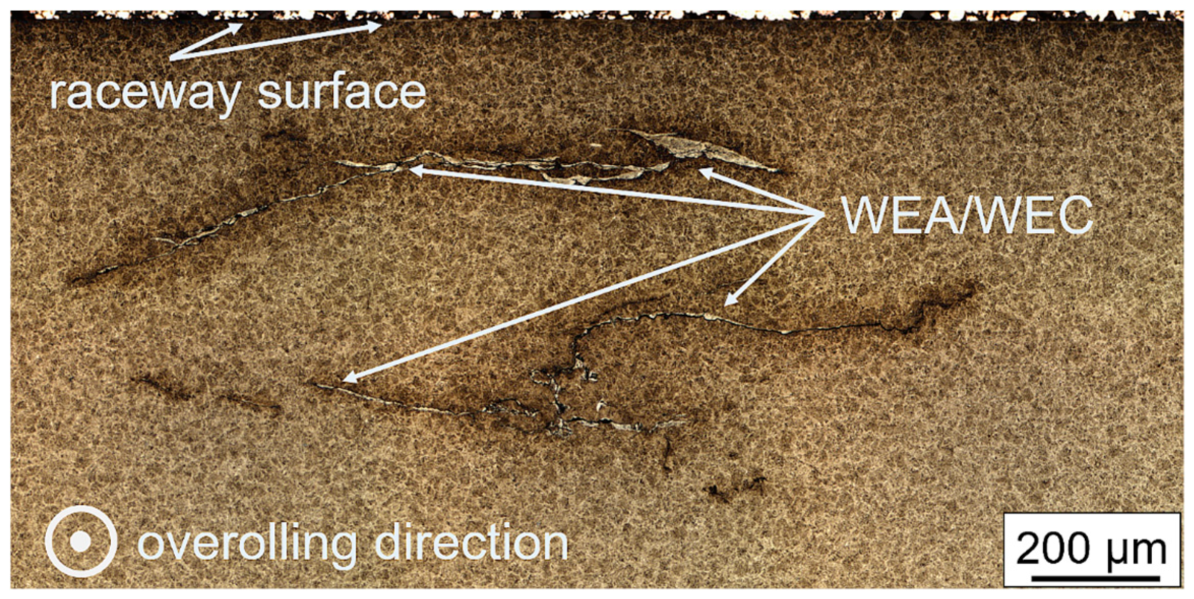
3.3. Identification of WEA/WEC

In order to get detailed information of the failed specimens, metallographic investigations were carried out. The examined followers were sectioned orthogonally to the over-rolling direction, where spalling damage was observable (exemplary shown in Figure 4). Furthermore, on the examined driver from test 6, sections were cut circumferentially in order to reveal the crack path into the depth and detect possible WEA in association with the axial cracks. All samples were prepared using standard metallographic methods. After preparation, samples were etched in 3% nital solution for imaging with light optical microscopy.
Summing up the analysis carried out on the followers, the morphology of the WEA/WEC areas can be described as zones, which are mostly horizontally orientated to the over-rolling direction. Typical appearance of the damaged area can be seen in Figure 5. Similar observations regarding the orientation of the WEC have been made for cylindrical roller thrust bearings tested under similar conditions [12].
Furthermore, the location of the affected areas correlates roughly with the location of the maximum von Mises stress σv, calculated to be 214 µm (1.4 GPa) below the raceway surface, this observation has also been made in the aforementioned investigations on cylindrical roller thrust bearings [12]. However, the advanced damage pattern does not allow reliable conclusions to be drawn with regard to the initiation mechanism.
As aforementioned and besides isolated WEC, axial cracks were found in driver from test 6. It is worth reiterating again, that no WEA were observed in association with the examined axial cracks.
Further investigation of one axial crack by forced fracture showed that the crack initiation and propagation had taken place below the surface. According to [5] the occurrence of the axial cracks can be caused by bulk tensile stresses superposed with material defects, which can be seen as crack initiators below the surface.

4. Discussion

Rolling contact fatigue tests conducted in the present study showed that the formation of WEC is influenced by lubrication regime, SRR and the slip type (±). The formation of WEC takes place preferentially under negative slip and boundary lubrication conditions.

4.1. Influence of Lubrication Regime

As previously described, the tests running under full fluid lubrication showed no signs of WEC formation. Furthermore, as can be seen from Figure 6 it can be argued that under boundary lubrication and a roughly constant SRR the run time until failure increases as λ increases.
These results are consistent with investigations on a four-disc test rig under boundary lubrication (λ = 0.06–0.7) in which the author suggested that the extent of the WEC damage increases as the lambda value decreases [10].
The stronger development of the WEC under boundary lubrication could be attributed to two key aspects. According to [1,18] the aforementioned observations might be consistent with hydrogen diffusion into steel, which is a confirmed WEC driver [1,2,9]. It has been demonstrated, that the decomposition of the lubricant—due to catalytic reactions with a nascent steel surfaces in sliding contacts—can lead to the generation of atomic hydrogen [19]. Moreover, the amount of generated hydrogen correlates with the amount of wear-induced nascent steel surface [19], which in a simplified approach, can be assumed to increase as the lambda value decreases [1].
In addition, the lubrication regime can influence the mechanism of crack growth in rolling/sliding contacts (as explained in the next section). According to [15], the traction force acting on the contact surfaces is greatly reduced under full fluid lubrication. Hence, there is no significant lubricant penetration into the surface crack, limiting not only the crack propagation but also the liberation of highly diffusible hydrogen at the crack tips.

4.2. Influence of Sliding and Slip Type

As illustrated in Figure 5, a decrease in the SRR at a constant λ-value, leads to decrease in run time until failure. This observation is against the expectations and the findings on a four-disc test rig, in which the author observed a reversed effect [10]. It should be noted, that the results are yet to be confirmed statistically and further studies are needed to validate this initial observation.
The higher tendency towards the development of crack networks under negative slip could be attributed to two mechanisms. It has been shown, that a volume element under negative slip is exposed to a higher material stress, resulting from the Hertzian pressure, the traction force and the temperature in the contact zone [17].
Moreover, it is well established that the surface crack growth and propagation is favored by negative slip [16]. It has been shown that, a crack formed on the surface under negative slip grows faster than its equivalent under positive slip [15,16]. As described in [15], this effect can be traced back to the lubricant penetrating the crack causing a rise in the hydraulic pressure—upon a contact body entering the contact zone—and ultimately leading to a further crack growth. A detailed description of crack growth and propagation mechanisms can be found in [15].

5. Conclusions

Following conclusions can be drawn from this study:
(1)
The prevailing lubrication conditions seem to have a dominant influence on the formation of WEC under rolling contact. Tests under full fluid lubrication (λ > 3) did not show any material damage (after the pre-defined running times), whereas WEC formation occur on tests running under boundary lubrication conditions (λ < 1).
(2)
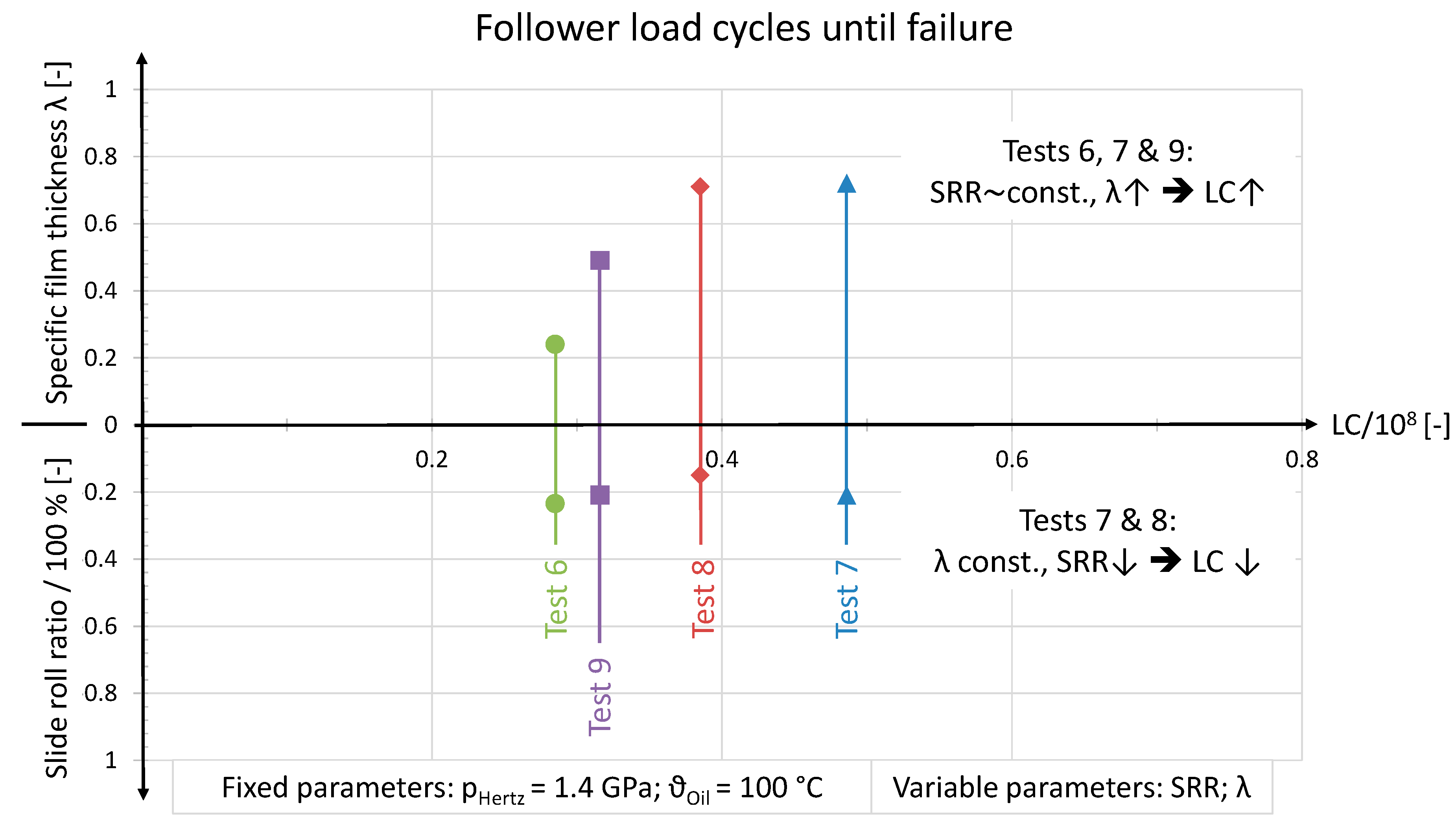
Maintaining a roughly constant SRR while increasing the λ-value from 0.2 to 0.5 and 0.7 leads to an increase of the running time by 11% and 54% respectively.
(3)
By decreasing the SRR from 21.0% to 15% and maintaining the same λ-value, the running time decreased (against the expectations) by 20%.
(4)
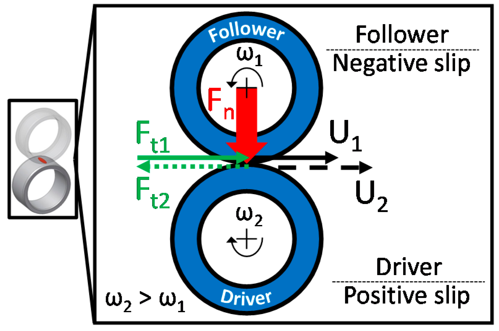
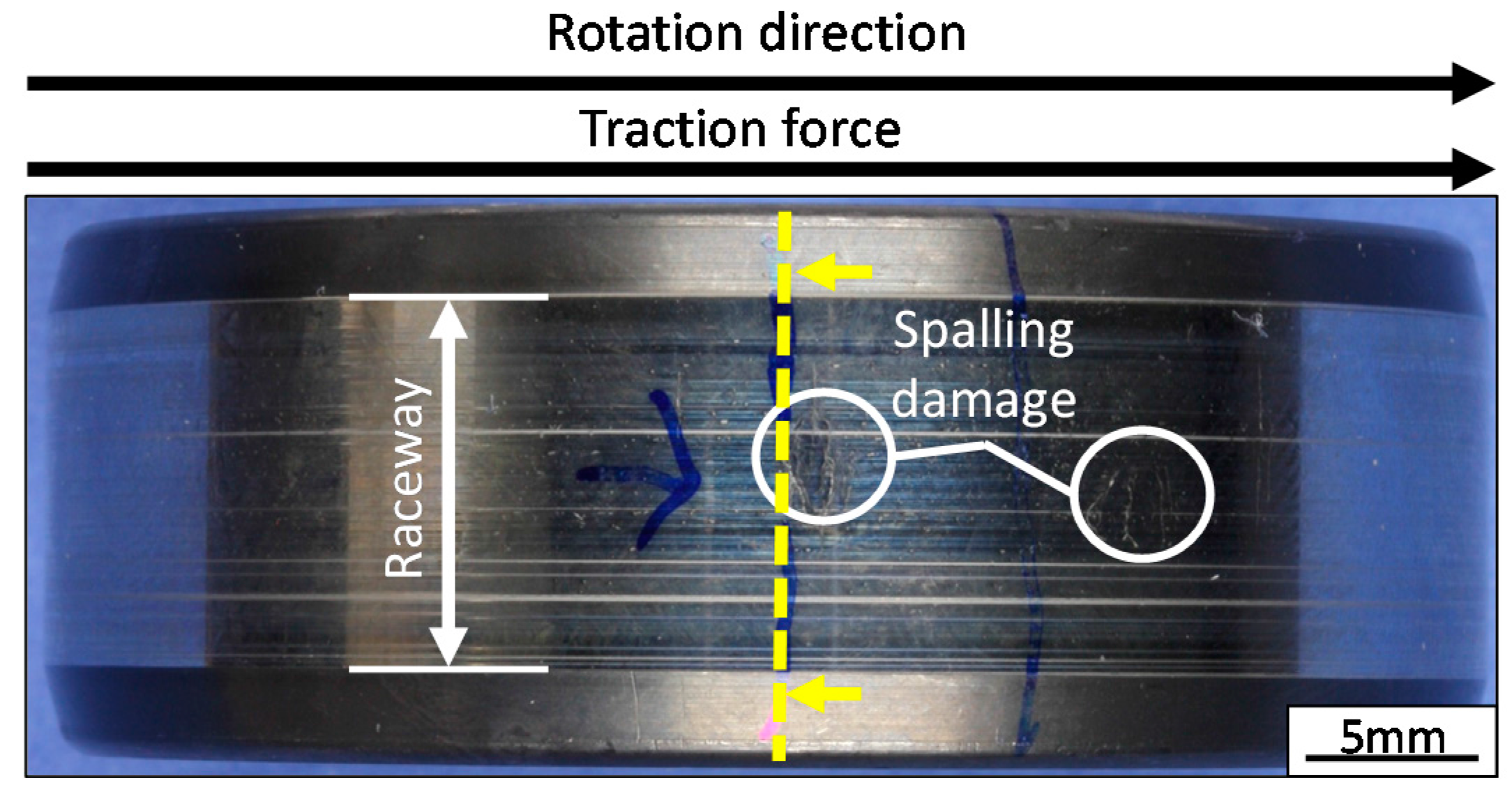
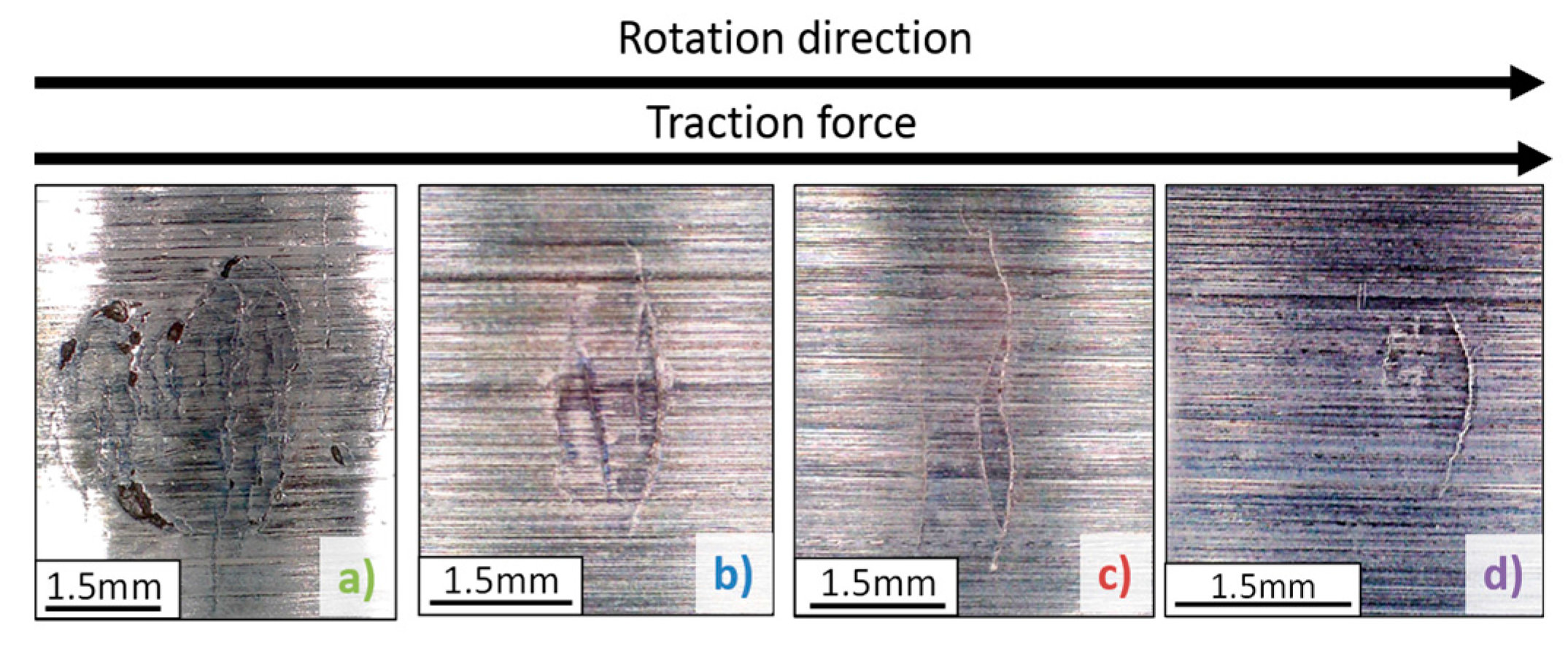
The slip type influences the extent of the WEA/WEC damage. Whereas the test rings that experienced negative slip showed large WEA/WEC networks—which spread mainly parallel to the raceway surface—the rings running positive slip showed considerably less WEA/WEC.

Acknowledgments

The research project FVA 707 II (IGF-Nr. 17904) was supported by the Federal Ministry of Economic Affairs and Energy (BMWi) based on a decision by the German Bundestag. The authors would like to thank the Forschungsvereinigung Antriebstechnik e.V. for the financial support and the helpful advice on the research projects FVA 707 I and II.

Author Contributions

Francisco Gutiérrez Guzmán and Mehmet Ozan Oezel wrote the article, designed and performed the experiments and analysis and analyzed the data. Georg Jacobs and Gero Burghardt supervised the work, discussed the basic design of experiments with Francisco Gutiérrez Guzmán and provided suggestions for the final discussion. Christoph Broeckmann and Thomas Janitzky discussed the metallographic investigations with Mehmet Ozan Oezel and provided suggestions for the final discussion.

Conflicts of Interest

The authors declare no conflicts of interest.

References

  1. Evans, M.H. An updated review: White etching cracks (WECs) and axial cracks in wind turbine gearbox bearings. Mater. Sci. Technol. 2016, 32, 1133–1169. [Google Scholar] [CrossRef]
  2. Evans, M.H. White Structure Flanking Failure in Bearings under Rolling Contact Fatigue. Ph.D. Thesis, University of Southampton, Southampton, UK, 2013. [Google Scholar]
  3. Diederichs, A.M.; Schwedt, A.; Mayer, J.; Dreifert, T. Electron microscopy analysis of structural changes within white etching areas. Mater. Sci. Technol. 2016, 32, 1683–1693. [Google Scholar] [CrossRef]
  4. Hiraoka, K.; Nagao, M.; Isomoto, T. Study on flaking process in bearings by white etching area generation. J. ASTM Int. 2006, 3, 1–7. [Google Scholar] [CrossRef]
  5. Lai, J.; Stadler, K. Investigation on the mechanisms of white etching cracks (WEC) formation in rolling contact fatigue and identification of a root cause for bearing premature failure. Wear 2016, 364–365, 244–256. [Google Scholar] [CrossRef]
  6. Greco, A.; Shengb, S.; Kellerb, J.; Erdemira, A. Material wear and fatigue in wind turbine systems. Wear 2013, 302, 1583–1591. [Google Scholar] [CrossRef]
  7. Li, S.; Su, Y.; Shu, X.; Chen, J. Microstructural evolution in bearing steel under rolling contact fatigue. Wear 2017, 380–381, 146–153. [Google Scholar] [CrossRef]
  8. Holweger, W.; Wolf, M.; Merk, D.; Blass, T.; Goss, M.; Loos, J.; Barteldes, S.; Jakovics, A. White etching crack root cause investigation. Tribol. Trans. 2014, 58, 56–59. [Google Scholar] [CrossRef]
  9. Ruellan, A.; Ville, F.; Lieber, X.; Arnaudon, A.; Girodin, D. Understanding white etching cracks in rolling element bearings: The effect of hydrogen charging on the formation mechanisms. J. Eng. Tribol. 2014, 228, 1252–1265. [Google Scholar] [CrossRef]
  10. Gould, B.; Greco, A. Investigating the Process of White Etching Crack Initiation in Bearing Steel. Tribol. Lett. 2016, 62, 26. [Google Scholar] [CrossRef]
  11. Loos, J.; Bergmann, I.; Goss, M. Influence of currents from electro-static charges on WEC formation in rolling bearings. Tribol. Trans. 2016, 59, 865–875. [Google Scholar] [CrossRef]
  12. Danielsen, H.K.; Gutiérrez Guzmánb, F.; Dahl, K.V.; Li, Y.J.; Wu, J.; Jacobs, G.; Burghardt, G.; Faster, S.; Alimadadih, H.; Goto, S.; et al. Multiscale characterization of White Etching Cracks (WEC) in a 100Cr6 bearing from a thrust bearing test rig. Wear 2016, 370–371, 73–82. [Google Scholar] [CrossRef]
  13. Dowson, D.; Higginson, G.R. Elasto Hydrodynamic Lubrication; Pergamon Press: Oxford, UK, 1977. [Google Scholar]
  14. Murakami, Y.; Kaneta, M.; Yatsuzuka, H. Analysis of Surface Crack Propagation in Lubricated Rolling Contact. ASLE Trans. 1985, 28, 60–68. [Google Scholar] [CrossRef]
  15. Kaneta, M.; Yatsuzuka, H.; Murakami, Y. Mechanism of Crack Growth in Lubricated Rolling/Sliding Contact. ASLE Trans. 1985, 28, 407–414. [Google Scholar] [CrossRef]
  16. Soda, N.; Yamamoto, T. Effect of Tangential Traction and Roughness on Crack Initiation/Propagation during Rolling Contact. ASLE Trans. 1982, 25, 198–206. [Google Scholar] [CrossRef]
  17. Sommer, K.; Heinz, R.; Schoefer, J. Verschleiß Metallischer Werkstoffe-Erscheinungsformen Sicher Beurteilen; Vieweg+Teubner Verlag, Springer Fachmedien Wiesbaden GmbH: Wiesbaden, Germany, 2010. [Google Scholar]
  18. Kruhöffer, W.; Loos, J. WEC Formation in Rolling Bearings under Mixed Friction: Influences and “Friction Energy Accumulation” as Indicator. Tribol. Trans. 2017, 60, 516–529. [Google Scholar] [CrossRef]
  19. Kohara, M.; Kawamura, T.; Egami, M. Study on Mechanism of Hydrogen Generation from Lubricants. Tribol. Trans. 2006, 49, 53–60. [Google Scholar] [CrossRef]
Figure 1. Two-disc test rig.
Lubricants 06 00008 g001
Figure 2. Kinematics of the two-disc test rig.
Lubricants 06 00008 g002
Figure 3. Images of the NU208-ring surfaces from test 6 (a); 7 (b); 8 (c) and 9 (d).
Lubricants 06 00008 g003
Figure 4. Plane of sample extraction (Follower—Test 6 (a)).
Lubricants 06 00008 g004
Figure 5. Detailed image of etched cross section (Follower—Test 6 (a)).
Lubricants 06 00008 g005
Figure 6. Plotted results—boundary lubrication.
Lubricants 06 00008 g006
Table 1. Elemental analysis of the lubricant (ICP).
S (ppm)P (ppm)Zn (ppm)Ca (ppm)Mg (ppm)
8343512616391950
Table 2. Test conditions.
TestPHertz (GPa)ϑOil (°C)SRR (%)λ (-)
Fluid lubrication11.260010.3
28.315.4
38.37.1
412.719.1
Boundary lubrication51.47012.80.78
610023.50.24
721.00.72
815.00.71
921.00.49
Table 3. Test results—full fluid lubrication.
TestLoad Cycles (Mio.)Results from Metallography
-FollowerDriverFollowerDriver
140.940.9No WECNo WEC
237.640.9No WECNo WEC
339.342.7N.A.N.A.
435.540.3N.A.No WEC
Table 4. Test results—boundary lubrication.
TestLoad Cycles (Mio.)Results from Metallography
-FollowerDriverFollowerDriver
510.512.0No WECNo WEC
628.536.1WEC (Spalling)Axial Cracks + WEC
748.660.0WEC (Spalling)N.A. (No Spalling)
838.544.7WEC (Spalling)N.A. (No Spalling)
931.639.0WEC (Spalling)WEC (Spalling)

