Crack Propagation in Honeycomb Cellular Materials: A Computational Approach

Politecnico di Torino, Department of Structural, Geotechnical and Building Engineering, Corso Duca degli Abruzzi 24, 10129 Torino, Italy
Metals 2012, 2(1), 65-78; https://doi.org/10.3390/met2010065
Submission received: 29 November 2011
/
Revised: 13 January 2012
/
Accepted: 2 February 2012
/
Published: 13 February 2012
(This article belongs to the Special Issue Nanocrystalline Metals and Alloys)
Abstract
:Computational models based on the finite element method and linear or nonlinear fracture mechanics are herein proposed to study the mechanical response of functionally designed cellular components. It is demonstrated that, via a suitable tailoring of the properties of interfaces present in the meso- and micro-structures, the tensile strength can be substantially increased as compared to that of a standard polycrystalline material. Moreover, numerical examples regarding the structural response of these components when subjected to loading conditions typical of cutting operations are provided. As a general trend, the occurrence of tortuous crack paths is highly favorable: stable crack propagation can be achieved in case of critical crack growth, whereas an increased fatigue life can be obtained for a sub-critical crack propagation.
Nomenclature
a = crack length (m)
amax = crack length corresponding to the component failure (m)
C = parameter of the Paris’ law (m (MPa√m)−m)
d = rod diameter (m)
 = diameter of the micro-grains (m)
E = Young’s modulus (N/m2)
 = critical opening displacement of the interfaces of level 1 (m)
 = critical opening displacement of the interfaces of level 2 (m)
 = fracture energy of the interfaces of level 1 (J/m2)
 = fracture energy of the interfaces of level 2 (J/m2)
 = strain energy release rate for crack deflection into one material (J/m2)
 = strain energy release rate for delamination (J/m2)
 = fracture energy of a material used in LEFM simulations (J/m2)
 = fracture energy of the interface used in LEFM simulations (J/m2)
KIC = material fracture toughness (MPa m1/2)
KICint = interface fracture toughness (MPa m1/2)
m = exponent of the Paris’ law (-)
N = number of cycles (-)
Pc = critical load for brittle crack propagation (N)
P* = average horizontal load measured during cutting conditions (N)
t = interface thickness (m)
ν = Poisson’s ratio (-)
ψ = inclination of the cellular rods with respect to the horizontal axis (°)
 = maximum (or peak) cohesive traction of the interfaces of level 1 (N/m2)
 = maximum (or peak) cohesive traction of the interfaces of level 2 (N/m2)
 = peak stress of the homogenized stress-strain curves (N/m2)
1. Introduction
Hard materials subjected to extreme loading conditions, high temperatures and severe impacts, as in case of cutting tools, have been the subject of extensive research to improve their performance. For instance, reducing the grain size of the material micro-structure down to the nanoscale is a common way to increase hardness, strength and wear resistance [1]. However, in spite of these enhanced properties, ultrafine grained materials may have shortcomings due to their brittle behavior, with a reduced toughness as compared to their large grain counterpart. Hence, a trade-off is often necessary in industrial applications to achieve high hardness and strength, with a sufficient resistance to cracking.
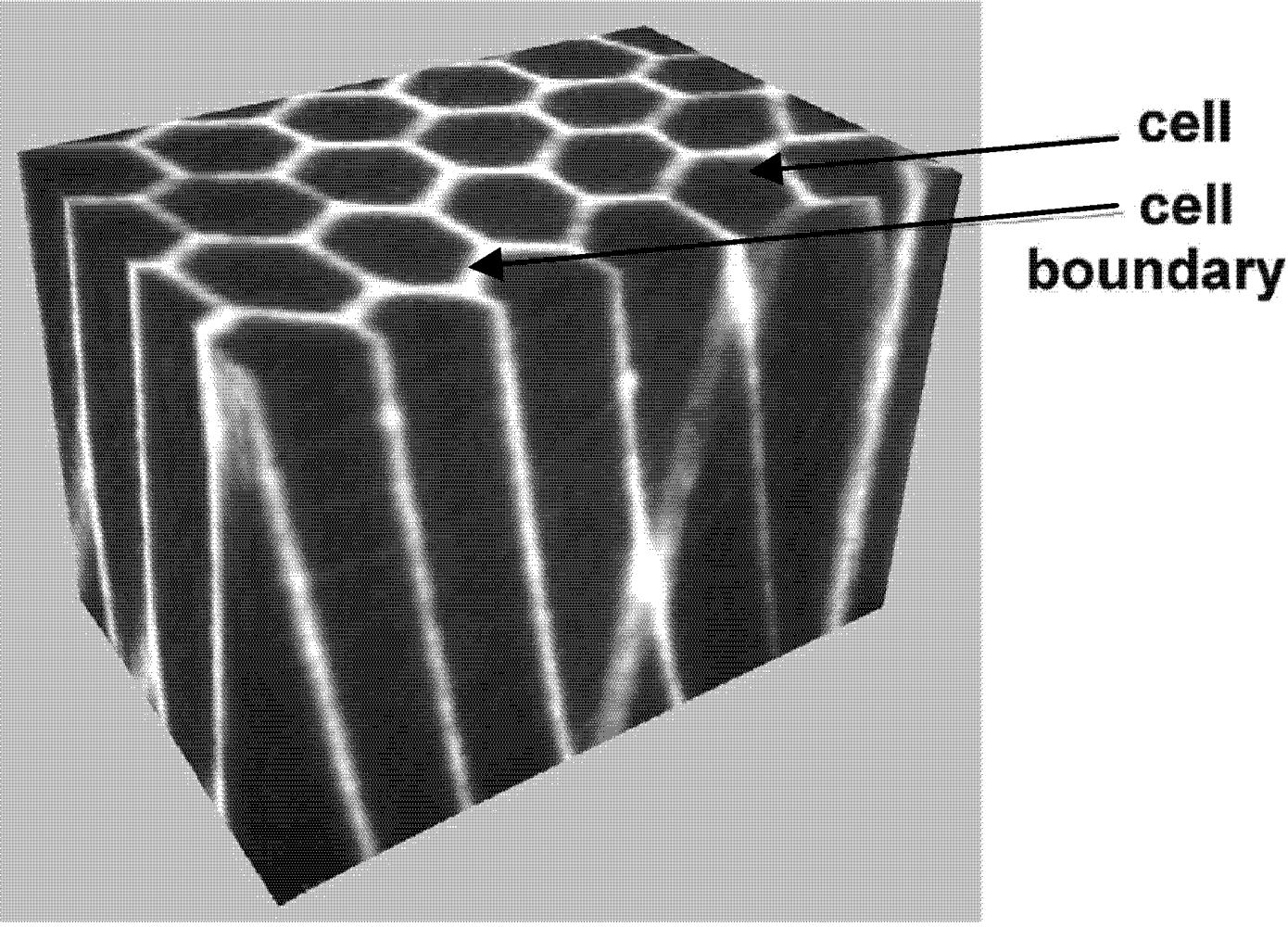
Recently, the introduction of functionally designed micro-structures opened new possibilities. In 2001, Fang et al. [2] sintered a new type of material that was called “structured”, see Figure 1. Very hard polycrystalline diamond (PCD) rods (also called cells) are embedded into thick WC-10 wt% Co (cemented Tungsten carbide with 10 wt% of Cobalt) cell boundaries. The fabrication procedure requires blending of graded powders of polycrystalline diamond and WC-10% Co with polymer binder, separately. The obtained PCD/polymer mixture is used to form the rods. The assembly of rods is then co-extruded several times, until the required cell size is obtained. As a result of these operations, a honeycomb structure is observed at any cross-section of the produced components. Preliminary experimental results concerning the fracture behavior of these materials are very promising. As crack deflection can increase the life of laminate composites by modifying the crack path [3], a similar effect was noticed for these honeycomb cellular materials [2]. The WC-Co cell boundary deflects and interrupts crack propagation and reduces the size of each individual chipped part. As a result, the macro-chipping failure mode, which involves a significant amount of material for a homogeneous PCD [4], is reduced or prevented. Hence, the reduction of the size of the chipped portions allows us to enhance the functionality of the component and to increase its service life.
Figure 1.
Scheme of a functionally designed cellular microstructure (reprinted with permission from [5]).
Figure 1.
Scheme of a functionally designed cellular microstructure (reprinted with permission from [5]).

Clearly, the presence of several design parameters makes the connection between the microstructure properties and the final mechanical response hard to be quantified. In particular, the presence of interfaces over different scales (finite thickness interfaces separating the cells and the grain boundaries between the PCD grains) makes the material characterization particularly challenging. At present, there is a lack of information about the effect of interface properties over multiple scales on the overall structural response. Understanding this connection is of paramount importance in order to improve the mechanical properties by tailoring the interface characteristics. In this context, virtual testing using numerical methods taking into account the heterogeneous composition of the material is expected to be beneficial.
In the present study, interfaces are not considered as simple defects, i.e., weak points of the material microstructure that limit the achievement of the maximum theoretical strength. The connection between interface characteristics and mechanical response is explicitly investigated, aiming at determining optimal configurations through tailoring of interface fracture parameters. This approach is in line with the research in composite [6] and biological structures [7], where interfaces play an active role in the realization of optimized mechanical responses. In Section 2, the effect of a hierarchy assembly of interfaces over two-level micro-structures is numerically investigated. The cohesive zone model (CZM), widely applied for nonlinear fracture mechanics characterization of materials and interface mechanical problems [8,9,10,11,12,13,14], is used to describe the nonlinear interface response. It will be shown that the tensile strength can be significantly enhanced by suitably modifying the interface characteristics. In Section 3, the global response of the cutting tool in terms of brittle crack propagation and fatigue crack growth is numerically analyzed. Since the focus is the structural analysis of the whole component used in cutting tools, the detailed finite element (FE) model used in Section 2 is not viable due to its high computational cost. Hence, a FE model based on linear elastic fracture mechanics (LEFM) accounting for interface crack propagation is devised. For both failure mechanisms, stable and unstable crack growth, the presence of interfaces between the rods is found to be beneficial.
2. Fracture Mechanics of Honeycomb Cellular Materials: The Role of the Two-Level Micro-Structure
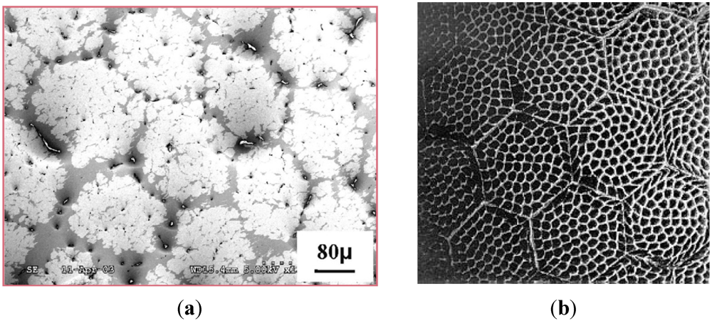
In this section, the role of the two-level micro-structure on the fracture mechanics response of honeycomb cellular materials is numerically investigated using the finite element method and nonlinear fracture mechanics. To this purpose, let us consider the cross-sections of the material micro-structure shown in Figure 2.
Figure 2.
Cross-sections of polycrystalline diamond (PCD) cellular rods with thick cell boundaries ((a) is reprinted with permission from [5]; (b) is adapted from [15]).

This material is an example of a hierarchical composite, where two distinct structural levels can be recognized. At the level 1, polycrystalline diamond (PCD) grains inside the cellular rods are separated by interfaces and represent the material micro-structure. The grain boundaries can be more or less regular, as we can recognize by comparing Figure 2(a,b). In Figure 2(b), the grain shape can be reasonably well approximated by hexagons. The cellular rods are separated by thick interfaces made of WC-10 wt% Co and represent the level 2, or meso-structure. In Figure 2(a), the thickness of these interfaces is approximately 30 μm and a porosity can be observed. In general, the porosity can locally modify the interface properties, leading to a statistical variability of interface fracture parameters. This aspect, which is not considered in the present work, is worth investigating in the future.
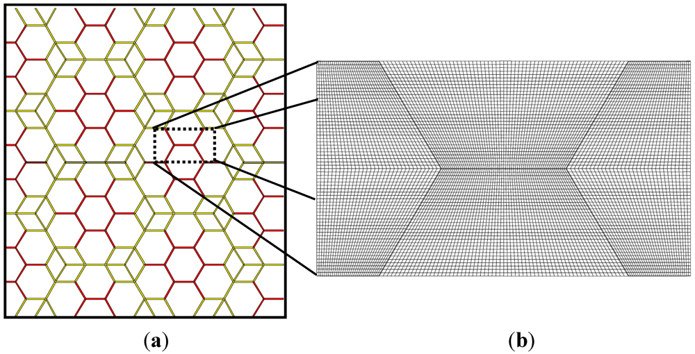
Hence, at both levels we have material interfaces that are expected to influence the mechanical response. Experiments [2] show that fracture is often the result of crack propagation along the cell and grain boundaries, with the occurrence of interface decohesion. Hence, the cohesive zone model (CZM), which sets up a relation between cohesive tractions and relative opening and sliding displacements at the imperfect interfaces, is appropriate for the physical description of this form of damage. In the present work, the methodology recently proposed in [16,17] is adopted. Finite thickness interfaces are simplified by considering rods separated by zero-thickness interface elements whose constitutive law is set up in terms of cohesive tractions vs. relative opening and sliding displacements. However, instead of using a standard CZM, the new nonlocal CZM proposed in [16] is used, since it takes into account the finite thickness properties of the interfaces. In this framework, a damage mechanics formulation describes the evolution of damage in the finite thickness region and leads to the final shape of the CZM which is not imposed a priori. For more details about the mathematical formulation and the numerical implementation of this CZM into the Finite Element Analysis Program (FEAP) developed by Zienkiewicz and Taylor [18], the reader is referred to [16,17]. A sketch of the interfaces of the level 1 (micro-structure) is shown in Figure 3(a) in red, whereas the interfaces of the level 2 (meso-structure) are depicted in green in the same figure. A magnification of the FE mesh of one portion of the domain is also shown in Figure 3(b).
Figure 3.
(a) 2D model of a cross-section of the hierarchical cellular polycrystalline material (cohesive zone model (CZM) interface elements of the interfaces of the levels 1 and 2 are shown in red and green, respectively); (b) Detail of the finite element (FE) mesh.
Figure 3.
(a) 2D model of a cross-section of the hierarchical cellular polycrystalline material (cohesive zone model (CZM) interface elements of the interfaces of the levels 1 and 2 are shown in red and green, respectively); (b) Detail of the finite element (FE) mesh.

The statistical variability of interface fracture properties may affect the crack path in case of intergranular crack propagation, especially inside the PCD rods. In this regards, the CZM in [16] can take into account the statistical variability of interface fracture properties. This issue has been investigated in [17] for standard polycrystalline materials. In the present work, however, the focus is on structural hierarchy and this problematic is left to future investigations.
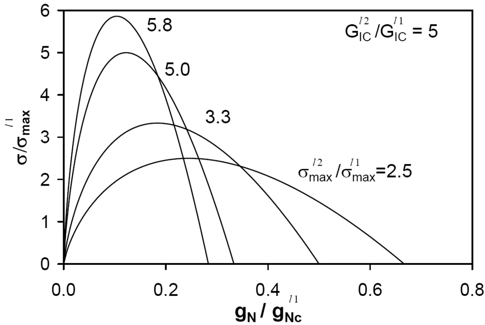
Note that the micro- and meso-structures are not physically similar if different constitutive laws are used at the two levels. As a practical example, we consider interfaces at the second level to be tougher than those of the first level. In particular, ![Metals 02 00065 i014]() is selected, where
is selected, where ![Metals 02 00065 i008]() is the Mode I fracture energy of the interface at a given level, evaluated as the area under the CZM traction-separation curve. This choice is consistent with the experimental observation that the thick cell boundaries are much tougher than the cell interior material. Keeping constant the CZM parameters of the interfaces of level 1, different CZM shapes are considered for the interfaces of level 2, as shown in Figure 4 in case of pure Mode I deformation. Here,
is the Mode I fracture energy of the interface at a given level, evaluated as the area under the CZM traction-separation curve. This choice is consistent with the experimental observation that the thick cell boundaries are much tougher than the cell interior material. Keeping constant the CZM parameters of the interfaces of level 1, different CZM shapes are considered for the interfaces of level 2, as shown in Figure 4 in case of pure Mode I deformation. Here, ![Metals 02 00065 i010]() denotes the peak cohesive traction of the interfaces of level 1, and
denotes the peak cohesive traction of the interfaces of level 1, and ![Metals 02 00065 i002]() is the critical relative opening displacement corresponding to vanishing cohesive tractions, always for level 1. The parameter
is the critical relative opening displacement corresponding to vanishing cohesive tractions, always for level 1. The parameter ![Metals 02 00065 i011]() denotes the peak cohesive traction of the interfaces of level 2.
denotes the peak cohesive traction of the interfaces of level 2.
 is selected, where is the Mode I fracture energy of the interface at a given level, evaluated as the area under the CZM traction-separation curve. This choice is consistent with the experimental observation that the thick cell boundaries are much tougher than the cell interior material. Keeping constant the CZM parameters of the interfaces of level 1, different CZM shapes are considered for the interfaces of level 2, as shown in Figure 4 in case of pure Mode I deformation. Here, denotes the peak cohesive traction of the interfaces of level 1, and is the critical relative opening displacement corresponding to vanishing cohesive tractions, always for level 1. The parameter denotes the peak cohesive traction of the interfaces of level 2.
 Figure 4.
Shapes of the CZMs of the interfaces between the rods (level 2 or meso-structure).

Simulating virtual tensile tests on a representative volume element (RVE) of the material by imposing a monotonic horizontal displacement to the finite element nodes on the vertical sides of the RVE, the homogenized response can be computationally determined. The RVE is selected as to isolate the smallest repetitive part of the meso-structure.
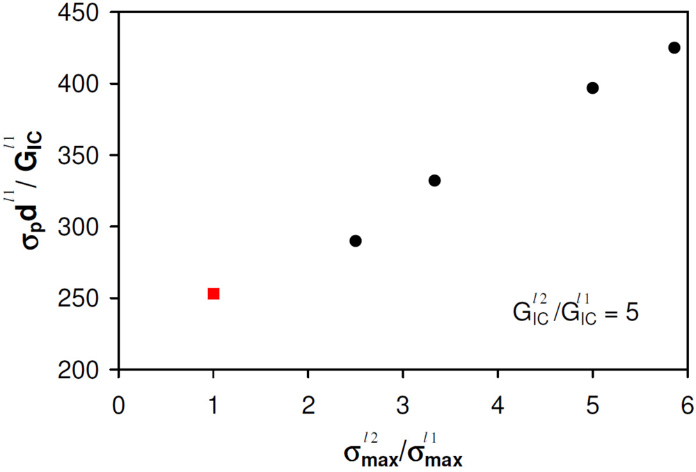
Figure 5.
Dimensionless tensile strength vs. CZM peak stress ratio between levels 2 and 1.

The peak stress of the homogenized stress-strain curves, ![Metals 02 00065 i012]() , obtained from a parametric analysis is plotted in Figure 5 vs. the ratio
, obtained from a parametric analysis is plotted in Figure 5 vs. the ratio ![Metals 02 00065 i017]() . The peak stresses are made dimensionless using the Mode I fracture energy of level 1,
. The peak stresses are made dimensionless using the Mode I fracture energy of level 1, ![Metals 02 00065 i004]() , and the grain size diameter,
, and the grain size diameter, ![Metals 02 00065 i001]() , of the grains composing the rods. In this diagram, the response of a standard polycrystalline material without structural hierarchy, which coincides with the response of the RVE with red interfaces only, is shown in Figure 5 with a red square. The results clearly pinpoint that the tensile strength can be significantly increased by using a hierarchical microstructure if the properties of the interfaces of level 2 are suitably selected. The interfaces of level 2 act as crack-arresters for the micro-cracks propagating into level 1. This fundamental mechanism is consistent with the qualitative experimental observation in [2], where the honeycomb cellular micro-structure leads to chipped parts of reduced sizes as compared to what happens in standard PCDs.
, of the grains composing the rods. In this diagram, the response of a standard polycrystalline material without structural hierarchy, which coincides with the response of the RVE with red interfaces only, is shown in Figure 5 with a red square. The results clearly pinpoint that the tensile strength can be significantly increased by using a hierarchical microstructure if the properties of the interfaces of level 2 are suitably selected. The interfaces of level 2 act as crack-arresters for the micro-cracks propagating into level 1. This fundamental mechanism is consistent with the qualitative experimental observation in [2], where the honeycomb cellular micro-structure leads to chipped parts of reduced sizes as compared to what happens in standard PCDs.
, obtained from a parametric analysis is plotted in Figure 5 vs. the ratio  . The peak stresses are made dimensionless using the Mode I fracture energy of level 1, , and the grain size diameter, , of the grains composing the rods. In this diagram, the response of a standard polycrystalline material without structural hierarchy, which coincides with the response of the RVE with red interfaces only, is shown in Figure 5 with a red square. The results clearly pinpoint that the tensile strength can be significantly increased by using a hierarchical microstructure if the properties of the interfaces of level 2 are suitably selected. The interfaces of level 2 act as crack-arresters for the micro-cracks propagating into level 1. This fundamental mechanism is consistent with the qualitative experimental observation in [2], where the honeycomb cellular micro-structure leads to chipped parts of reduced sizes as compared to what happens in standard PCDs.
3. Crack Patterns, Global Structural Response and Structural Integrity Considerations at the Component Level
The results in Section 2, obtained by performing virtual tensile tests on RVEs, are important from the materials science point of view, since they show that a suitable modification of interface properties can be beneficial for the tensile strength. However, from the structural integrity point of view, it is important to assess the effect of the cellular micro-structure on crack propagation inside a full-sized composite tool when subjected to real loading conditions. The complexity of modeling crack propagation due to loads experienced during real cutting regards the possible presence of crack branching and multiple cracks. Experimental images of cracked components in [2], however, show that failure is often the result of a single prevailing crack propagating along the boundaries of the cellular rods.
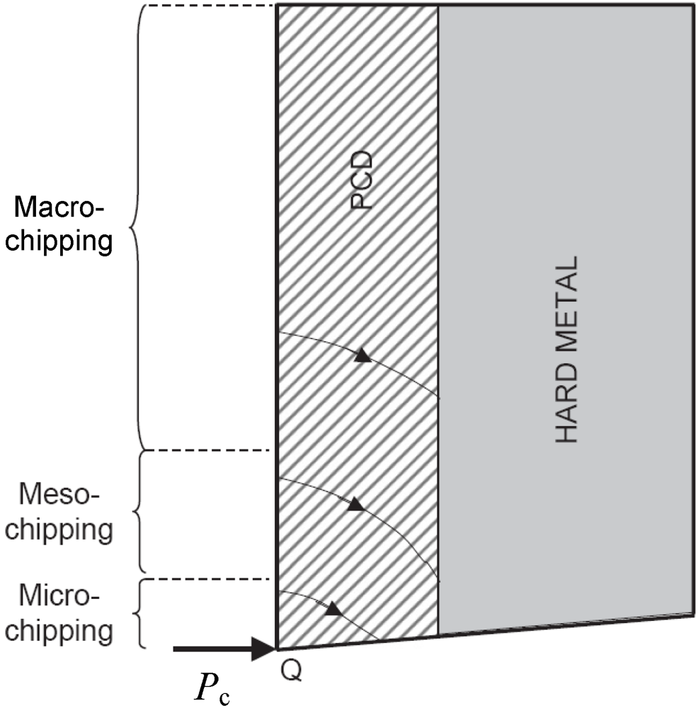
Here, a multi-material component is considered, where an external layer made of PCD cells is bonded to a hard metal substrate (see Figure 6). The substrate is also made of WC-Co and it is constrained to horizontal and vertical displacements on the side opposite to the load. These boundary conditions are representative of the bit of a cutting tool, as modeled in [8]. This composite structure is usually joined to a steel support, which is not modeled in the present case. In fact, the steel support can be considered as a boundary condition to the composite PCD bit, where fracture phenomena take place. A typical thickness of the PCD layer is of the order of 1 mm.
Figure 6.
Sketch of a PCD bit used in cutting tools (reprinted with permission from [8]). The critical impact load is denoted by Pc and different possible failure modes ranging from micro- to macro-chipping are sketched.
Figure 6.
Sketch of a PCD bit used in cutting tools (reprinted with permission from [8]). The critical impact load is denoted by Pc and different possible failure modes ranging from micro- to macro-chipping are sketched.

When subjected to repeated loadings, as during cutting operations, different failure modes may occur. In case of a horizontal load concentrated at the tool tip, Pc, micro-, meso- and macro-chipping can take place, depending on the initiation point of a crack on the vertical side in tension, see Figure 6. Moreover, different failure mechanisms, i.e., brittle crack propagation or fatigue crack growth, may also occur. A detailed investigation of the failure modes and fracture mechanisms for homogeneous PCD layers is available in [8].
To investigate the effect of the rods on the crack pattern and on the stability of crack propagation, a FE model of the PCD layer with a cellular meso-structure is proposed. A rod diameter d = 200 μm and an interface thickness t = 30 μm are considered. At this scale of observation, the rods are modeled as a homogeneous material with E = 855 GPa and ν = 0.2. This is a reasonable approximation at this scale, since the size of the grains is much smaller than the size of the rods. Similarly, the thick cell boundaries of WC-Co are also modeled as a linear elastic material with E = 543 GPa and ν = 0.23. Since the fracture process zone is quite small at this scale of observation, linear elastic fracture mechanics is adopted to simulate crack propagation. A 2D model of the tool is considered, although crack propagation is essentially 3D in reality. In spite of that, 2D simulations for homogeneous PCD layers compared favorably well with experimental trends [8]. An initial edge notch inside a rod is introduced along the free vertical side of the tool. Its initial size is 20 μm, comparable with the size of the existing micro-defects observed in these materials [8]. The fracture parameters of WC-Co, PCD and the bi-material interfaces are KIC(PCD) = 10.5 MPa m1/2, KIC(WC-Co) = 30.0 MPa m1/2 and KIC(int) = 20 MPa m1/2, see also [8].
Specific crack propagation criteria have to be considered for simulating interface fracture in the framework of linear elastic fracture mechanics. Among the criteria generally used, a distinction has to be made between local and global ones. Local fracture criteria can be used in those cases where the elastic fields lose self-similarity or the crack may not remain coplanar as it propagates [19]. These criteria are based on quantities related to the series expansion of the elastic fields in the neighborhood of the crack tip. For brittle materials, an example of a local fracture criterion is represented by the modified version of the Erdogan and Sih [20] maximum circumferential stress criterion proposed by Piva and Viola [21] for the study of an elastic system consisting of two bonded dissimilar materials with a crack along their common interface. The following assumptions are made in this criterion, considering for instance a bi-material system with one material occupying the region ![Metals 02 00065 i018]() and the other the region
and the other the region ![Metals 02 00065 i019]() :
:
 and the other the region
  :
:- (1) Crack propagation takes place along the interface or in one of the two adjacent materials along the direction
![Metals 02 00065 i020]() (i = 1, 2) for which the circumferential stress, evaluated at a small distance
(i = 1, 2) for which the circumferential stress, evaluated at a small distance ![Metals 02 00065 i021]() from the crack tip, is maximum.
from the crack tip, is maximum. - (2) Crack propagation begins as soon as one of the following conditions is satisfied:


where ![Metals 02 00065 i023]() and
and ![Metals 02 00065 i024]() are the critical stress-intensity factors of the two components and
are the critical stress-intensity factors of the two components and ![Metals 02 00065 i025]() is a critical parameter taking into account the adhesive interface bonding strength.
is a critical parameter taking into account the adhesive interface bonding strength.
 and
and  are the critical stress-intensity factors of the two components and
  is a critical parameter taking into account the adhesive interface bonding strength.
 On the other hand, global fracture criteria are essentially based on the energy balance and are generally applicable under the condition that the crack propagates along an interface or into a homogeneous medium [22]. Applications to the study of mixed-mode crack problems were also proposed by Gupta [23]. For instance, let consider the problem consisting of a crack which starts at the interface between two different materials. Clearly, two possibilities may occur during propagation: to continue to move along the interface giving rise to pure delamination, or to move out of the interface into one of the two material regions. According to He and Hutchinson [22] and to He et al. [24], it is possible to assume that the interface, like a continuum, presents a resistance to cracking, i.e., a critical interface fracture energy ![Metals 02 00065 i009]() . In this respect, the conditions for pure delamination along the bi-material interface, or for deflection into one of the material regions, can be stated using a strain energy-based failure criterion. In doing so, we consider first the ratio between the strain energy release rate for delamination and the critical interface fracture energy,
. In this respect, the conditions for pure delamination along the bi-material interface, or for deflection into one of the material regions, can be stated using a strain energy-based failure criterion. In doing so, we consider first the ratio between the strain energy release rate for delamination and the critical interface fracture energy, ![Metals 02 00065 i026]() , and then the ratio between the strain energy release rate for crack deflection into one of the constituent materials and the corresponding critical value of the strain energy release rate,
, and then the ratio between the strain energy release rate for crack deflection into one of the constituent materials and the corresponding critical value of the strain energy release rate, ![Metals 02 00065 i027]() . The crack continues to propagate along the interface if
. The crack continues to propagate along the interface if
. In this respect, the conditions for pure delamination along the bi-material interface, or for deflection into one of the material regions, can be stated using a strain energy-based failure criterion. In doing so, we consider first the ratio between the strain energy release rate for delamination and the critical interface fracture energy,  , and then the ratio between the strain energy release rate for crack deflection into one of the constituent materials and the corresponding critical value of the strain energy release rate,
  . The crack continues to propagate along the interface if
otherwise it deflects into one of the neighborhood materials. This failure criterion was implemented in the FE Fracture ANalysis Code (FRANC2D) by Ingraffea and Wawrzynek [25,26] and it will be used in the present study. In particular, the following algorithm is adopted:
- (1) For each material region around a crack tip:
- find the direction of the maximum tensile circumferential stress;
- remesh to add a finite crack increment in this direction;
- solve the resulting FE equations;
- normalize the global change in strain energy with respect to the crack increment and compute the ratio with the critical energy release rate.
- (2) For each interface around the crack tip:
- extend the crack a finite distance along the interface;
- solve the resulting FE equations;
- use the relative opening and sliding at the crack tip to determine the load angle and the critical strain energy release rate;
- normalize the change in strain energy with respect to the crack increment and find the ratio with the critical strain energy release rate.
- (3) The direction of propagation is that with the largest associated ratio of the rate of energy release to the critical rate of energy release.
The use of the energy criterion is preferred here to the strength criterion. For crack propagation inside homogeneous materials, the global and the local criteria give predictions that fall in a very narrow band [27]. On the other hand, for interface crack propagation problems, the use of the energy balance criterion is motivated by the numerical comparisons proposed by Červenka et al. [28]. They showed that, for the portion of crack growth along the bi-material interface, the energy release rate tends to remain almost constant, contrary to the stress-intensity factors related to circumferential and shearing stresses that are functions of the crack length. Therefore, from the numerical point of view, the energy balance criterion is considered to be more robust and appropriate for interface crack simulations.
Considering the mechanical stress field due to a horizontal force acting at the tool tip, a magnification of the crack path is shown in Figure 7.
Figure 7.
Fracture of a cutter with a cellular microstructure: scheme of the compact bit (left) and magnification of the crack path in the region inside the rectangular dashed box (right).
Figure 7.
Fracture of a cutter with a cellular microstructure: scheme of the compact bit (left) and magnification of the crack path in the region inside the rectangular dashed box (right).

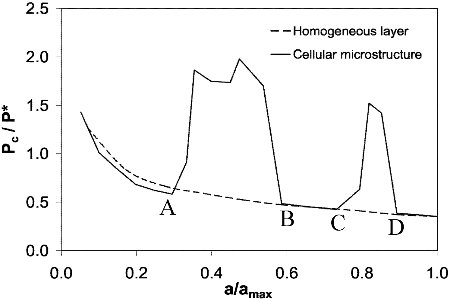
The critical load for crack propagation, Pc, which corresponds to the critical condition for crack propagation at each step, is shown in Figure 8 vs. the crack length a. The load P* represents the average load typically experienced during experimental tests for homogeneous PCDs. This value is determined from a statistics of cutting tests where the horizontal acceleration of the tool is measured [8]. The parameter amax is the final crack length when the crack meets the hard metal substrate and failure of the component takes place. At the beginning of the simulation, the crack propagates into a PCD road, and therefore there is no difference with respect to the propagation into a standard homogeneous material, at least in 2D simulations (see Figure 7 up to the point labeled A). When the crack tip meets the bi-material interface, delamination of the rod takes place (path A–B in Figure 7). Since the interface fracture energy is higher than that of the PCD, the external applied load required for crack propagation has to be significantly increased with respect to the homogeneous case. Subsequently, the crack deviates again into the rod (path B–C). A second peak is finally observed when the crack propagates through the binder between the cells (path C–D).
These results are important as far as the issue of stability of crack propagation is concerned (see Figure 8). A crack would arrest its propagation at the first interface if the dimensionless applied load is lower than 2.0. This situation is substantially different from the case of a homogeneous layer, whose response is shown with dashed line in Figure 8. In this case, the critical dimensionless load is a monotonic decreasing function of the crack length. As a consequence, when the dimensionless applied load exceeds 1.5, then the crack cannot be arrested. Therefore, the use of a cellular microstructure is beneficial and may arrest a crack thereby controlling its propagation.
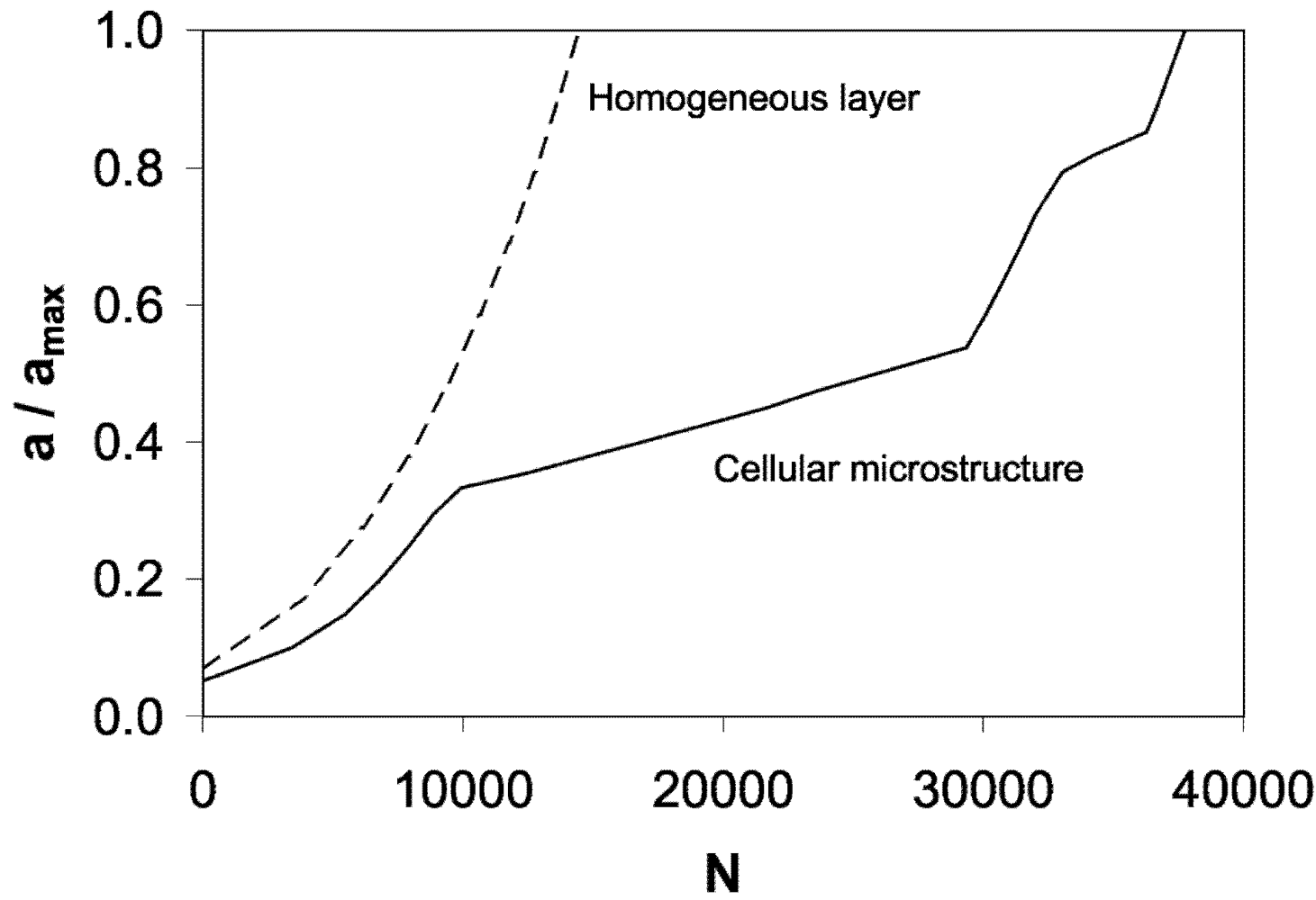
For subcritical crack propagation, which may occur in case of repeated forces of magnitude lower than Pc, similar numerical simulations can be performed and the Paris’ law can be applied to determine the crack growth rate, da/dN:

where C and m are the Paris’ law parameters, a is the crack length, N is the number of cycles and ![Metals 02 00065 i030]() is the stress-intensity factor range experienced at the crack tip during a cyclic load from zero to a maximum value of the external applied force. The computed crack growth rate can be finally integrated in order to determine the corresponding loading cycles, N. Using the Paris’ law parameters adopted in [8] for the same material combination, the fatigue life of a cellular microstructure is predicted to be approximately four times longer than that of a homogeneous layer (see Figure 9).
is the stress-intensity factor range experienced at the crack tip during a cyclic load from zero to a maximum value of the external applied force. The computed crack growth rate can be finally integrated in order to determine the corresponding loading cycles, N. Using the Paris’ law parameters adopted in [8] for the same material combination, the fatigue life of a cellular microstructure is predicted to be approximately four times longer than that of a homogeneous layer (see Figure 9).
 is the stress-intensity factor range experienced at the crack tip during a cyclic load from zero to a maximum value of the external applied force. The computed crack growth rate can be finally integrated in order to determine the corresponding loading cycles, N. Using the Paris’ law parameters adopted in [8] for the same material combination, the fatigue life of a cellular microstructure is predicted to be approximately four times longer than that of a homogeneous layer (see Figure 9).
Figure 8.
Dimensionless critical load for brittle crack propagation vs. dimensionless crack length. The response of a cellular microstructure is compared with that of a homogeneous layer.
Figure 8.
Dimensionless critical load for brittle crack propagation vs. dimensionless crack length. The response of a cellular microstructure is compared with that of a homogeneous layer.

Figure 9.
Dimensionless crack length vs. loading cycles. The response of a cellular microstructure is compared with that of a homogeneous PCD layer.
Figure 9.
Dimensionless crack length vs. loading cycles. The response of a cellular microstructure is compared with that of a homogeneous PCD layer.

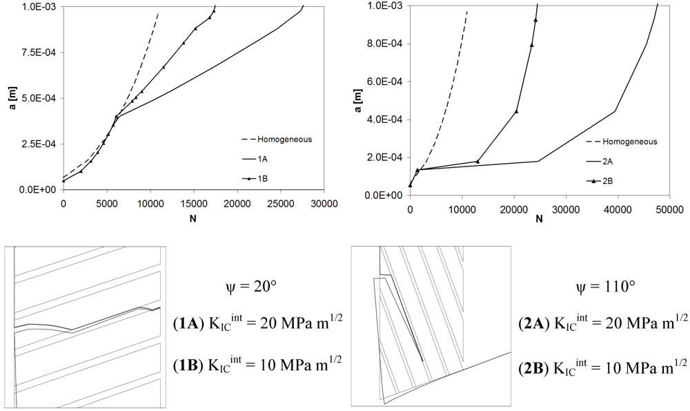
The effects of rods’ inclination and interface fracture toughness are also investigated and the results are shown in Figure 10. Two different meso-structures are considered, with a rod inclination angle of 20° or 110° with respect to the horizontal axis. In both cases, a rod diameter equal to 200 μm and a finite thickness interface of 30 μm are selected. The crack deviates along the bi-material interface very soon in both cases and regardless of the value of the interface fracture toughness used in the simulations. In general, the configuration 2 (ψ = 110°) is more convenient than configuration 1 (ψ = 20°), since it leads to a longer fatigue life. In both cases, the use of tougher interfaces is beneficial. For comparison, the response of the homogeneous PCD layer without meso-structure is reported in Figure 10 with dashed line.
Figure 10.
The effects of rods’ inclination and interface fracture toughness on fatigue life.

4. Conclusion and Future Perspectives
In this study it has been shown that functionally designed micro-structures can offer enhanced mechanical properties as compared to traditional polycrystalline materials. Tailoring of interface properties is the way to enhance the material tensile strength as compared to standard polycrystals. Moreover, interfaces can be used to enforce crack propagation along pre-defined paths, increasing the critical load for brittle crack propagation and the fatigue life of structural components. However, further investigations in this direction are necessary, especially regarding the effect of cellular structures on the properties related to contact mechanics, i.e., hardness and wear resistance. From the computational point of view, 3D simulations can offer more capabilities to investigate interface crack propagation problems with more than 2 hierarchical levels. However, the computational cost significantly increases and multi-scale solution techniques should be invoked. Another important aspect deserving further investigations is the role of porosity and defects in the finite thickness interfaces. A possibility could be the run of stochastic fracture mechanics simulations with a random distribution of interface properties, provided that the connection between the degree of porosity and the CZM parameters is established.
Acknowledgments
The support of the Italian Ministry of Education, University and Research (MIUR), Ateneo Italo-Tedesco, and the Deutscher Akademischer Austausch Dienst (DAAD) to the Vigoni Project “3D modeling of crack propagation in polycrystalline materials” is gratefully acknowledged.
References
- Langdon, T.G. The processing of ultrafine-grained materials through the application of severe plastic deformation. J. Mater. Sci. 2007, 42, 3388–3397. [Google Scholar]
- Fang, Z.K.; Griffo, A.; White, B.; Lockwood, G.; Belnap, D.; Hilmas, G.; Bitler, J. Fracture resistant super hard materials and hardmetals composite with functionally graded microstructure. Int. J. Refract. Met. Hard Mater. 2001, 19, 453–459. [Google Scholar]
- Abisset, E.; Daghia, F.; Ladevèze, P. On the validation of a damage mesomodel for laminated composites by means of open-hole tensile tests on quasi-isotropic laminates. Compos. Part A 2011, 42, 1515–1524. [Google Scholar]
- Carpinteri, A.; Paggi, M. Numerical analysis of fracture mechanisms and failure modes in bi-layered structural components. Finite Elem. Anal. Des. 2007, 43, 941–953. [Google Scholar]
- Functional design puts the bite into hard and refractory metals. Met. Powder Rep. 2003, 58, 20–25.
- Park, S.-J.; Seo, M.-K. Interface Science and Composites; Acedemic Press: New York, NY, USA, 2011. [Google Scholar]
- De Santis, R.; Ambrosio, L.; Mollica, F.; Netti, P.; Nicolais, L. Mechanical properties of human mineralized connective tissues. In Modeling of Biological Materials; Mollica, F., Preziosi, L., Rajagopal, K.R., Eds.; Birkhäuser: Boston, MA, USA, 2007; chapter 6. [Google Scholar]
- Carpinteri, A. Cusp catastrophe interpretation of fracture instability. J. Mech. Phys. Solids 1989, 37, 567–582. [Google Scholar]
- Carpinteri, A. Softening and snap-back instability in cohesive solids. Int. J. Numer. Methods Eng. 1989, 28, 1521–1537. [Google Scholar]
- Corigliano, A.; Allix, O. Some aspects of interlaminar degradation in composites. Comput. Methods Appl. Mech. Eng. 2000, 185, 203–224. [Google Scholar]
- Mroz, Z.; Giambanco, G. An interface model for analysis of deformation behaviour of discontinuities. Int. J. Numer. Anal. Methods Geomech. 1996, 20, 1–33. [Google Scholar]
- Giambanco, G.; Rizzo, S.; Spallino, R. Numerical of masonry structures via interface models. Comput. Methods Appl. Mech. Eng. 2001, 190, 6493–6511. [Google Scholar]
- Giambanco, G.; Turetta, T.; Borino, G. Elasto-plastic damaging interface model for the description of decohesion processes in composite structures. In Proceedings of the International Conference of Composites in Constructions CCC-2003, Cosenza, Italy, 16–19 September 2003.
- Carpinteri, A.; Paggi, M.; Zavarise, G. Snap-back instability in micro-structured composites and its connection with superplasticity. Strength Fract. Complex. 2005, 3, 61–72. [Google Scholar]
- Rigali, M.J.; Fulcher, M.R. Fibrous Monolith Wear Resistant Components for the Mining Industry; Advanced Ceramics Research: Tucson, AZ, USA, 2003; 3292 East Hemisphere Loop Dr., 85706-5013. Available online: http://www.osti.gov/bridge/purl.cover.jsp?purl=/829541-jVi73L/native (accessed on 29 November 2011).
- Paggi, M.; Wriggers, P. A nonlocal cohesive zone model for finite thickness interfaces—Part I: Mathematical formulation and validation with molecular dynamics. Comput. Mater. Sci. 2011, 50, 1625–1633. [Google Scholar]
- Paggi, M.; Wriggers, P. A nonlocal cohesive zone model for finite thickness interfaces—Part II: FE implementation and application to polycrystalline materials. Comput. Mater. Sci. 2011, 50, 1634–1643. [Google Scholar]
- Zienkiewicz, O.C.; Taylor, R.L. The Finite Element Method, 5th ed; Butterworth-Heinemann: Oxford, UK, 2000. [Google Scholar]
- Viola, E.; Piva, A. Plane strain interfacial fracture analysis of a biomaterial incompressible body. Eng. Fract. Mech. 1981, 15, 131–142. [Google Scholar]
- Erdogan, F.; Sih, G.C. On the crack extension in plates under plane loading and transverse shear. J. Basic Eng. 1963, 85, 1–7. [Google Scholar]
- Piva, A.; Viola, E. Biaxial load effects on a crack between dissimilar media. Eng. Fract. Mech. 1980, 13, 143–174. [Google Scholar]
- He, M.-Y.; Hutchinson, J.W. Crack deflection at an interface between dissimilar elastic materials. Int. J. Solids Struct. 1989, 25, 1053–1067. [Google Scholar]
- Gupta, G.D. Strain Energy release rate for mixed mode crack problem. In Proceedings of the American Society of Mechanical Engineers, Winter Annual Meeting, New York, NY, USA, 5–10 December 1976; 8 WA/PVP-7.
- He, M.-Y.; Evans, A.G.; Hutchinson, J.W. Crack deflection at an interface between dissimilar elastic materials: Role of residual stresses. Int. J. Solids Struct. 1994, 31, 3443–3455. [Google Scholar]
- Wawrzynek, P.A.; Ingraffea, A.R. Interactive finite element analysis of fracture processes: An integrated approach. Theor. Appl. Fract. Mech. 1987, 8, 137–150. [Google Scholar]
- Wawrzynek, P.A.; Ingraffea, A.R. Discrete Modeling of Crack Propagation: Theoretical Aspects and Implementation Issues in Two and Three Dimensions; Technical Report 91-5, School of Civil and Environmental Engineering, Cornell University: Ithaca, NY, USA, 1991. [Google Scholar]
- Wang, C.H. Fracture of interface cracks under combined loading. Eng. Fract. Mech. 1997, 56, 77–86. [Google Scholar]
- ervenka, J.; Chandra Kishen, J.M.; Saouma, V.E. Mixed mode fracture of cementitious bimaterial interfaces; part II: Numerical simulation. Eng. Fract. Mech. 1998, 60, 95–107. [Google Scholar] [CrossRef]
© 2012 by the authors; licensee MDPI, Basel, Switzerland. This article is an open-access article distributed under the terms and conditions of the Creative Commons Attribution license (http://creativecommons.org/licenses/by/3.0/).
Share and Cite
MDPI and ACS Style
Paggi, M. Crack Propagation in Honeycomb Cellular Materials: A Computational Approach. Metals 2012, 2, 65-78. https://doi.org/10.3390/met2010065
AMA Style
Paggi M. Crack Propagation in Honeycomb Cellular Materials: A Computational Approach. Metals. 2012; 2(1):65-78. https://doi.org/10.3390/met2010065
Chicago/Turabian StylePaggi, Marco. 2012. "Crack Propagation in Honeycomb Cellular Materials: A Computational Approach" Metals 2, no. 1: 65-78. https://doi.org/10.3390/met2010065