Article

Potential of Metal Fibre Felts as Passive Absorbers in Absorption Silencers

Institute for Materials, TU Braunschweig, Langer Kamp 8, Braunschweig D-38106, Germany
*
Author to whom correspondence should be addressed.
Metals 2013, 3(1), 150-158; https://doi.org/10.3390/met3010150
Submission received: 30 November 2012 / Revised: 19 February 2013 / Accepted: 22 February 2013 / Published: 5 March 2013

Abstract

:
The growing noise exposure of residents, due to a rising number of flights, causes significant impacts on physical health. Therefore it is necessary to reduce the noise emission of aircrafts. During take-off, the noise generated by the jet engines is dominating. One way to lower the noise emission of jet engines is to build an absorption silencer by using porous liners. Because of the high thermic and corrosive attacks as well as high fatigue loads, conventional absorbers cannot be used. A promising material is sintered metal fibre felts. This study investigates the suitability of metal fibre felts for the use as absorption material in silencers. The influences of pore morphology, absorption coefficient, determined with perpendicular sound incidence, as well as geometric parameters of the silencer to the damping are identified. To characterise the material, the parameters fibre diameter, porosity and thickness are determined using three-dimensional computer tomography images. The damping potential of absorption silencers is measured using an impedance tube, which was modified for transmission measurements. The essential parameter to describe the acoustic characteristics of porous materials is the flow resistivity. It depends on the size, shape and number of open pores in the material. Finally a connection between pore morphology, flow resistivity of the metal fibre felts and damping potential of the absorption silencer is given.

1. Introduction

The exposure to a high noise level, such as aircraft noise, causes insomnia, makes it difficult to concentrate and incurs further health damage [1,2]. The rising number of flights and the associated expansion of airports close to residential areas require a reduction of the aircrafts’ noise emission. Besides the aeroacoustic noise generated by flow around the aircraft, the engine noise is the most significant source of noise [3]. To reduce this noise, the future objective is to line the exhaust side of the engine’s hot gas path with porous absorbers. This would create an absorption silencer for the core engine. Because brittle ceramics would crack due to high fatigue loads and polymers cannot be used at high temperatures, metallic absorbers were chosen as porous liners. Sintered metal fibre felts of the alloy 1.4404 have a high porosity, which is a basic requirement for dissipative sound absorption, and are available with different pore sizes. Thus it is possible to optimize the flow resistivity to the frequency needed to be damped. These characteristics make sintered metal fibre felts well suited for the studies of silencers. A previous study, determining the absorption coefficient for a wide range of porous metals, supports this approach [4].

1.1. Dissipative Absorption

The dissipative sound absorption converts the kinetic energy of sound waves into thermal energy through friction [5]. For this purpose it is necessary for sound waves to enter the absorber and to experience a high energetic loss inside the material. In both cases the flow resistivity is the essential parameter, which is a function of the porosity and pore morphology. For a laminar flow through a capillary, the flow resistivity can be determined from the pore morphology using the law of Hagen–Poiseuille [6]. As the pore morphology of fibrous materials is irregular and the pores are no capillaries, other characteristic values are required for the description of sintered fibre felts. For fibrous material the hydraulic radius can be replaced by the viscous characteristic length, as defined by Johnson et al. (1986) [7,8]. To allow the sound wave to enter the absorber easily, a low flow resistivity is required. For a high friction loss, a high flow resistivity is needed. The ideal value of the flow resistivity depends on the frequency. Due to the fact that the absorption increases with the length of the path inside the absorber, the flow resistivity is usually considered multiplied by the absorber thickness.

1.2. Absorption Silencer

A channel lined homogeneously with a noise-absorbing material without a gap to the channel wall is considered an absorption silencer [9]. The damping that can be achieved with a silencer depends on the absorption coefficient α of the porous material, and therefore on the pore morphology (see [4]), and the dimensions of the silencer. For an absorption silencer of the length L, which has a circular cross section with the inner radius h, the damping DL can be estimated using the following form of the “Piening formula”:
D L =3 α h L

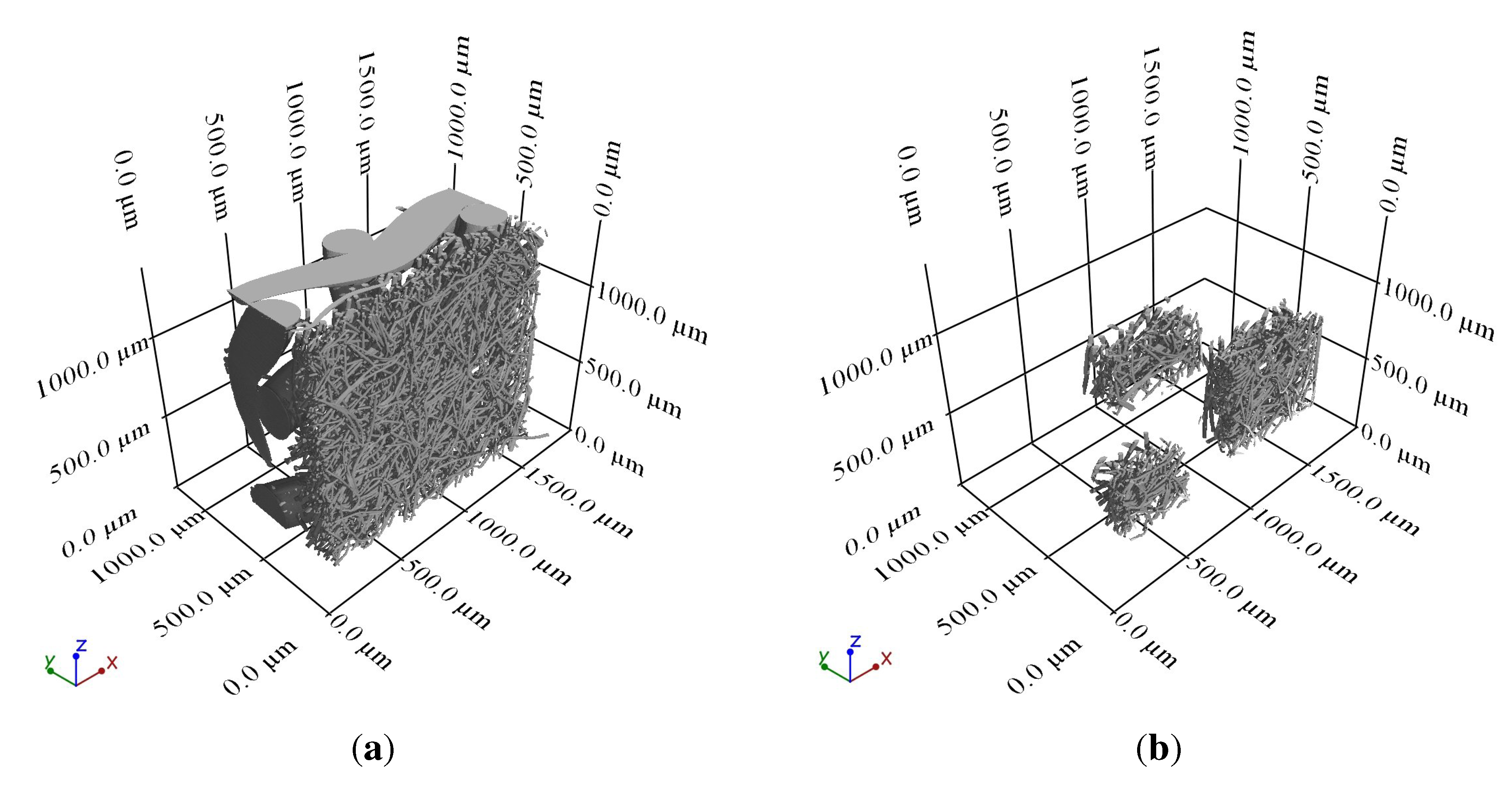
2. Material Characterisation

To characterize the material, the thickness t, the fibre diameter d and the porosity σ were determined using CT images. To prepare roughly rotationally symmetric samples for CT imaging, the fibre felts were embedded in a transparent polymer and cut into square sticks, about 2 mm thick. In this way, it is possible to place the samples close to the X-ray tube and reach the highest possible resolution. The length of the sticks varied but was kept short to avoid eccentric rotation. CT images are based on two-dimensional X-ray images. As these pictures consist of different grey values, depending on the thickness and density of the material, the reconstruction of a three-dimensional image is based on the interpretation of grey values. The critical step is to determine the surface by defining the threshold value and assign grey values to air or material. Considering the achieved voxel size V ≈ 1 µm, the fibre diameter can be measured with an accuracy of 2 µm. The advantage of the three-dimensional characterisation over the two-dimensional characterisation, using light or electron microscopes that have a much higher resolution, is the possibility to look at more than one plane. This allows taking the changes in porosity and fibre diameter into account. Furthermore, the cross-sectional shape of all fibres can be identified more clearly. For two dimensional images this is only possible if the fibres are perpendicular to the plane. To calculate the porosity, a rectangular volume that contains a representative volume of the sample and is as large as possible without including surrounding air was chosen. Using the previously determined surface, it is possible to distinguish between air and material. The percentage of air in the volume is equivalent to the porosity. As the fibre felts are not completely flat but slightly arched, the size of rectangular volumes including a representative part of the sample is limited. To include as much as possible of the sample, several volumes were analysed, as shown in Figure 1. The averaged results are given in Table 1. As mentioned above, the flow resistivity for fibrous materials can be calculated using the characteristic length, which is given by
Λ = 1 2 π L R
where L is the total length of fibres per unit volume and R is the fibre radius [8]. The total length of fibres per unit volume was calculated using the following equation:
L   =   1     σ π R 2  
The flow resistivity Ξ was then calculated by [8]:
Ξ = 8 η Λ 2 σ
For the dynamic viscosity of air the value η = 17, 7 µPas was used [10].
Table 1 contains the flow resistivity measured according to DIN EN 29053 (Ξ1) and the flow resistivity calculated with Equation 4 (Ξ2). All fibre felts are supported by a fibre grid with significantly larger dimensions (see Figure 1(a)). This support grid is not considered in the analysis. SFF 40 consists of two functional layers with different fibre diameters. Layer 1 is the outer layer without contact to the support grid, and layer 2 is the layer on the support grid. For the calculation of the flow resistivity, the mean value of the fibre diameter was used. Although the calculation of the flow resistivity is not very accurate, proper forecasts of the order of magnitude of the flow resistivity are possible. Note that Ξ1 was measured with support grid.
Figure 1. CT image of sintered fibre felt 40. (a) Complete sample; (b) Analysed volumes.
Metals 03 00150 g001
Table 1. Material properties of sintered fibre felts (SFF), porosity (σ), thickness of functional layer (t), fibre diameter of layers 1 and 2 (d1 and d2), flow resistivity measured by the Physikalisch-Technische Bundesanstalt in Braunschweig according to DIN EN 29053 (Ξ1), calculated flow resistivity (Ξ2).
Material σ/% t/µmd1/µmd2/µmΞ1/ kPas/m2Ξ2/ kPas/m2
SFF 40 87 ± 19 280 13 ± 2 24 ± 2 182 127 ± 87
SFF 50 86 ± 14 590 25 ± 2 -79 90 ± 45
SFF 70 92 ± 16 430 23 ± 2 --33 ± 18
SFF 100 92 ± 15 430 25 ± 2 -85 28 ± 14
SFF 120 89 ± 14 270 26 ± 2 -95 49 ± 24
SFF 150 94 ± 16 270 24 ± 2 -37 16 ± 8

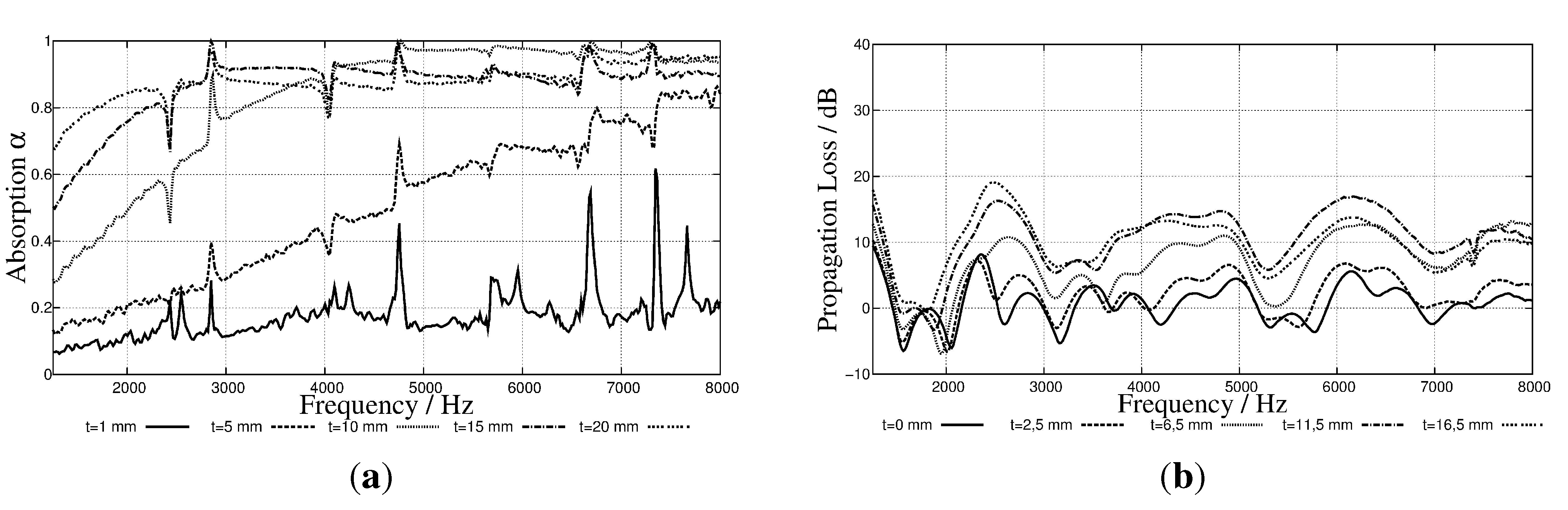
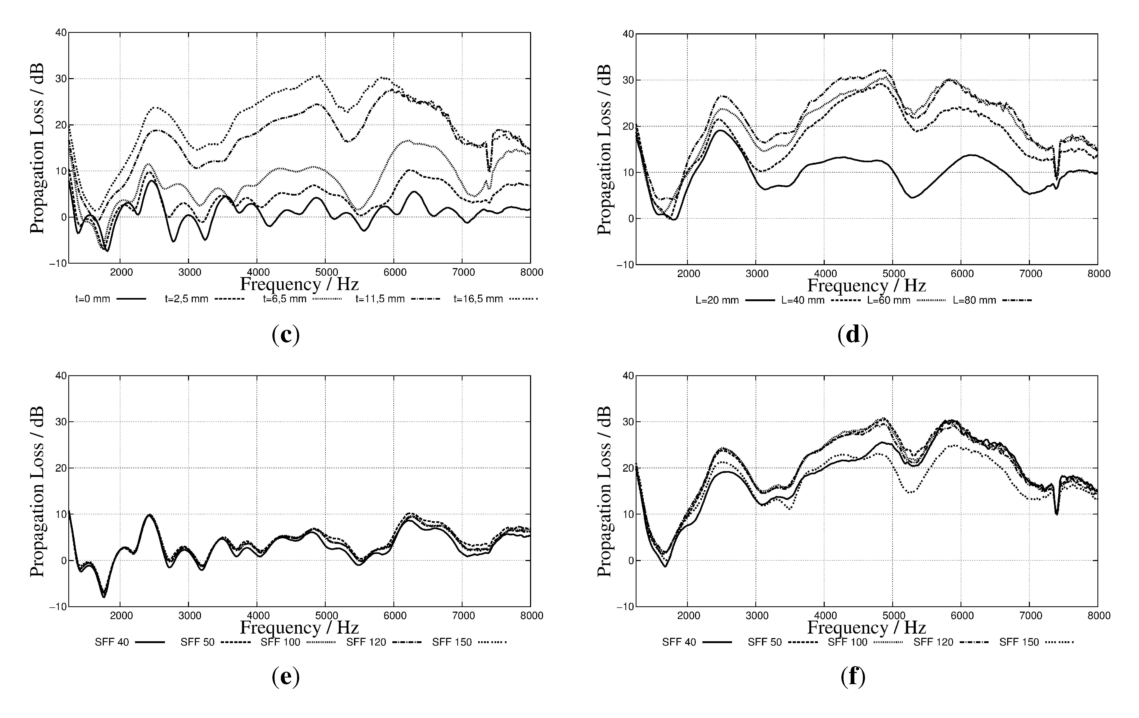
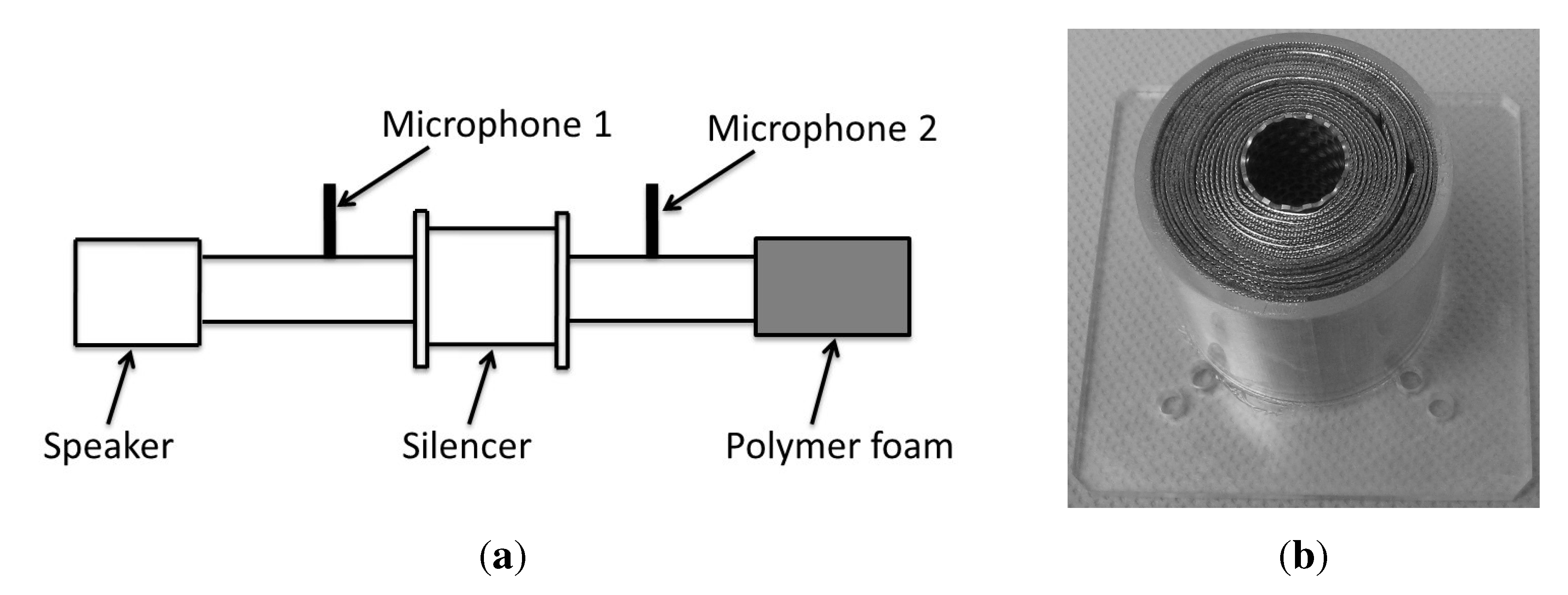
3. Attenuation Measurement

In an impedance tube occur, depending on the inner diameter of the tube, only plane sound waves. The direction of propagation of the sound wave is parallel to the axis of the silencer. The absorption coefficient α was measured using an impedance tube with an inner diameter of 19 mm, according to DIN EN ISO 10534-2 [4]. This impedance tube covers a frequency range from  fl = 1,25 kHz to fu = 10 kHZ. Results are given in Figure 2(a). For the attenuation measurement of the absorption silencer the same impedance tube was used to retain consistency. The inner diameter of the impedance tube and the silencer is much smaller than that one of a jet engine. Therefore the measured damping is high compared with silencers with the dimensions of jet engines (compare Equation 1). Nevertheless the effects of the different fibre felts and dimensions of the silencers are visible. To enable transmission measurements, the impedance tube was modified, see Figure 3. The sonically hard wall, which closed the tube, was removed and replaced by a polymer foam with a hole, corresponding to the inner diameter of the impedance tube. This is supposed to ensure a low level of reflections and make sure that no sound waves will run back into the tube. A microphone was placed on each side of the silencer to detect the sound pressure. This setup, deviating from a more complex setup according to ASTM E2611, is designed to have a low level of reflections and is suitable to compare the damping potential of different silencers. The silencer consists of a tube and two flanges of acrylic glass. The contact areas between the silencer and the impedance tube were greased to avoid loss. For the outer wall of the silencer, tubes with different lengths L and diameters (below considered as the silencer’s external diameter) were used, to vary these parameters. The silencer’s inner diameter was set to that of the impedance tube to avoid reflections. The sintered fibre felts were rolled on a perforated tube with the inner diameter of the impedance tube and inserted into the acrylic glass tube, see Figure 3(b). A perforated screen is a common cover to protect the absorber material [5,9]. The perforated tube used for the measurements has a perforation percentage of p = 56, 9% and can be regarded as acoustically transparent [9]. The sound wave will be damped not only in the silencer but also in the impedance tube. The propagation loss D between the two microphones was calculated from the sound pressure level measured in front of the inlet (Lp1) and behind the outlet (Lp2) of the silencer.
D = Lp1Lp2
To avoid random errors, every measurement was performed five times and the results were averaged. The measurement results for the frequency range f = 1,25 kHz to f = 8 kHz can be found in Figure 2. All measurements were performed at room temperature.
Figure 2. Propagation loss due to absorption silencers. (a) Absorption coefficient of SFF 50; (b) Propagation loss with SFF 50 and L = 20 mm; (c) Propagation loss with SFF 50 and L = 60 mm; (d) Propagation loss with SFF 50 and t = 16,5 mm; (e) Propagation loss with different sintered fibre felts with t = 2,5 mm and L = 60 mm; (f) Propagation loss with different sintered fibre felts with t = 16,5 mm and L = 60 mm.
Metals 03 00150 g002aMetals 03 00150 g002b
Figure 3. Experimental setup. (a) Impedance tube for transmission measurements; (b) Silencer.
Metals 03 00150 g003

4. Discussion

The attenuation measurement was performed using an impedance tube, which was modified for transmission measurement. Although a foam was used to ensure a low level of reflections, standing waves appeared during the measurement. In Figure 2(b–f), local minima and maxima of the propagation loss can be identified, which arise from the superposition of opposed waves. In Figure 2(b,c), the propagation loss for acrylic glass tubes, which are of the same length as the silencers, are shown as a reference (indicated as t = 0 mm). The appearance of standing waves makes it difficult to give absolute values for the damping of absorption silencers and identify the impact of dissipative absorption. However, different silencers remain comparable and the suitability of the sintered fibre felts for the use in absorption silencers can be assessed.
The propagation loss grows with an increase in the silencer’s length and external diameter. That was to be expected according to Equation 1. The silencer length has a direct impact on the damping. The external diameter is indirectly implied via the absorber thickness and the resulting absorption coefficient (see also [4]). In Figure 2(a) the absorption coefficient, of perpendicular incidence, is plotted against the frequency for absorbers with different thickness. With a low absorption coefficient (up to f ≈ 2000 Hz) only a low propagation loss can be reached; for higher frequencies, absorption coefficient and propagation loss are increasing. The comparison with Figure 2(b) shows clearly that the way the absorption coefficient develops with the frequency is transferable to the development of the damping of absorption silencers using the same porous absorption material. The second parameter besides the absorber thickness that influences the absorption coefficient as well as the damping is the pore morphology. It has a major influence on the flow resistivity and, therefore, on the absorption coefficient (see also [4]). For sintered fibre felts, an increase in fibre diameter and porosity induces a decreasing flow resistivity (see Table 1). As the damping depends on the absorption coefficient, it depends on the flow resistivity as well. A low flow resistivity enables the damping of low frequencies, but requires thicker absorbers [9]. The measurement results show that the increase of the propagation loss with an increase of the absorber thickness is smaller for sintered fibre felts that have a high flow resistivity than it is for sintered fibre felts with a low flow resistivity. Figure 2(f) shows that a decreasing flow resistivity up to a certain value (79 kPas/m2 ≥ Ξ ≤ 37 kPas/m2) induces an increase in damping. If this value is exceeded, the damping decreases again. This indicates that the flow resistivity must be optimized for the frequency range being observed. The increase in damping is most significant for SFF 50 to SFF 120 compared with SFF 40 for a frequency range from f = 2000 Hz to f = 5000 Hz. With an even lower flow resistivity, the damping decreases again. This effect can be observed with the use of SFF 150. Regarding geometric parameters, the optimal damping for the considered frequency range can be achieved with fibre felts that have a porosity of σ ≈ 90% and a fibre diameter of d ≈ 25 µm. Note that all measurements were performed at room temperature. Due to elevated temperatures in jet engines and changing properties of air, the frequency range best to be damped will move to higher frequencies; similarly, the required porosity, fibre diameter and absorber thickness will increase.
For silencers with the length L = 20 mm, the order of the damping is according to the order of the absorption coefficient. For L = 60 mm, the order of damping for different external diameters differs from that order. This effect can be explained with the superposition dissipative and reactive absorption. The abrupt changes in tube diameters from impedance tube to silencer and back effect multiple reflections in a resonator. This causes reactive absorption through the λ/4 principle, where the incident wave is eliminated through superposition with the reflected wave, if the resonator length is an odd-numbered multiple of λ/4 [3,11]. The longer the silencer is, the more high frequencies can be damped through the λ/4 principle. Therefore, the propagation loss for high frequencies consisting of dissipative and reactive damping effects will increase. The bigger is the change in tube diameters, the bigger is the damping effect through the λ/4 principle [11]. This can change the order of damping for certain frequencies from the order one would expect according to Equation 1. Similarly to the geometric parameters of the silencer, the porous absorption material has an influence on the reactive absorption. A decreasing flow resistivity causes an increase in the reactive absorption through the λ/4 principle [11]. This effect has to be regarded opposed to the decrease in damping for a certain frequency range with decreasing flow resistivity and constant absorber thickness. The material with the highest absorption coefficient does not necessarily achieve the highest damping in a silencer. The highest damping could be reached using a sintered fibre felt with the porosity σ ≈ 89%, the fibre diameter df ≈ 26 µm and flow resistivity Ξ ≈ 49 kPas/m2.

5. Conclusions

One way to reduce aircraft noise is to line jet engines with porous materials and build an absorption silencer for the core engine. For this study, lined hollow cylinders were used for sound transmission measurements. Due to the thermal and mechanical performances as well as high absorption coefficients, sintered fibre felts were chosen as porous liners. The experiments show that the way the absorption coefficient of sintered fibre felts changes with the frequency is transferable to the change of the damping of absorption silencers. The flow resistivity, defined by fibre diameter and porosity, has to be optimized according to a particular frequency range. Additionally to the dissipative absorption, reactive sound absorption effects occur that are superimposed. The total damping of different silencers might differ from the damping that was to be expected considering only the dissipative absorption. Note that standing waves occurred and that the inner diameter of the silencer is only 19 mm. Due to the much higher diameter of jet engines, the possible damping will decrease. Furthermore, the requirements for pore diameters will differ, due to changing properties of air with rising temperatures.

Acknowledgements

The authors would like to thank GKN sinter metals for providing sample materials. Financial support by the German federal state of Lower Saxony of the research program “Bu¨rgernahes Flugzeug” and by the German Research Foundation (Deutsche Forschungsgemeinschaft-DFG) in the framework of the “Sonderforschungsbereich 880” is greatly appreciated.

References

  1. Haines, M.M.; Stansfeld, S.A.; Job, R.F.S.; Berglund, B.; Head, J. Chronic aircraft noise exposure, stress responses, mental health and cognitive performance in school children. Psychol. Med. 2001, 31, 265–277. [Google Scholar]
  2. Franssen, E.A.M.; van Wiechen, C.M.A.G.; Nagelkerke, N.J.D.; Lebert, E. Aircraft noise around a large international airport and its impact on general health and medication use. Occup. Environ. Med. 2004, 61, 405–413. [Google Scholar] [CrossRef]
  3. Bräunling, W.J.G. Flugtriebwerke,3.,vollst. überarb. u. erw. Aufl.; Springer: Berlin, Germany, 2009; pp. 1309–1314. [Google Scholar]
  4. Hinze, B.; Rösler, J.; Lippitz, N. Noise reduction potential of cellular metals. Metals 2012, 2, 195–201. [Google Scholar] [CrossRef]
  5. Seddeq, H.S. Factors influencing acoustic performance of sound absorptive materials. Aust. J. Basic Appl. Sci. 2009, 3, 4610–4617. [Google Scholar]
  6. Böswirth, L.; Bschorer, S. Technische Strömungslehre-Lehr-und Übungsbuch, 9. Auflage; Vieweg+Teubner, Springer Fachmedien Wiesbaden GmbH: Wiesbaden, Germany, 2012; pp. 175–177. [Google Scholar]
  7. Johnson, D.L.; Koplik, J.; Schwartz, L.M. New pore-size parameter characterizing transport in porous media. Phys. Rev. Lett. 1986, 57, 2564–2567. [Google Scholar] [CrossRef]
  8. Allard, J.F.; Atalla, N. Propagation of Sound in Porous Media: Modelling Sound Absorbing Materials, 2nd ed.; John Wiley & Sons, Ltd: Hoboken, NJ, USA, 2009; pp. 79–81. [Google Scholar]
  9. Schirmer, W. Technischer Lärmschutz-Grundlagen und praktische Maβ nahmen zum Schutz vor Lärm und Schwingungen von Maschinen,2.,bearbeitete und erweiterte Auflage; Springer: Berling, Germany, 2006. [Google Scholar]
  10. Sigloch, H. Technische Fluidmechanik Achte,überprüfte und aktualisierte Auflage; Springer: Berlin, Germany, 2012; p. 453. [Google Scholar]
  11. Möser, M. Technische Akustik,8.,aktualisierte Aufl.; Springer: Berlin, Germany, 2009; pp. 285–329. [Google Scholar]

