Article

Morphology Analysis of a Multilayer Single Pass via Novel Metal Thin-Wall Coating Forming

State key Laboratory of Manufacturing System Engineering, Xi’an Jiaotong University, Xi’an 710049, China
*
Author to whom correspondence should be addressed.
Metals 2016, 6(12), 313; https://doi.org/10.3390/met6120313
Submission received: 30 June 2016 / Revised: 22 November 2016 / Accepted: 24 November 2016 / Published: 9 December 2016
(This article belongs to the Special Issue 3D Printing of Metals)

Abstract

:
Through using a novel micro-coating metal additive manufacturing (MCMAM) process in this study, the forming characteristics of the multilayer single-pass specimens were investigated. The forming defects including the porosity and the bonding quality between layers were analyzed. Moreover, we also attempted to study the effect of process parameters such as flow rate, deposition velocity, and layer thickness on the forming morphology. Based on the results, the optimization of process parameters was conducted for the fabrication of thin-wall MCMAM. Finally, estimation criteria for the integrity of the interfacial bond were established.

1. Introduction

Additive manufacturing (AM) has attracted much attention from the public due to its unique advantages, such as unrivalled design freedom and short lead times [1]. It can produce high-performance metal components rapidly using alloy powder or wires as raw material and applying a high-power laser or electron beam as a heat source [2,3,4,5]. However, the high capital costs and slow throughput printing have severely restricted its application.
To overcome the shortages of traditional AM, micro-coating metal additive manufacturing (MCMAM) has been proposed as a commercial manufacturing technology. Compared with traditional metal AM technologies, MCMAM has shown several advantages. At first, it provides a higher material utilization than selective laser melting (SLM) with a high deposition rate. Second, it produces less dust pollution than powder-based equipment when the powder material was recycled. Third, it has a lower equipment cost than SLM and electron beam machining (EBM) [6].
Xiong et al. investigated the forming characteristics of a multilayer single pass with the application of GMAW-based additive manufacturing [7]. Jorge et al. developed a fused deposition modeling (FDM) system for metals that can deposit electronic structures directly [8]. Yao et al. adopted a metal droplet deposition manufacturing process to reduce product development time as well as the cost of manufacturing [9]. However, deposition accuracy was difficult to control. In addition, the novel metal additive manufacturing process proposed in this paper was analyzed using a numerical simulation method. Nevertheless, the influences of process parameters on the forming morphology have never been mentioned [10].
Therefore, this paper is aimed at investigating the effects of the major process parameters on the forming morphology and the bonding quality between layers during the micro-coating additive manufacturing. Moreover, a statistical investigation on the surface finish of fabricated specimens was also performed.

2. Experimental Procedure

In order to increase the productivity and reduce cost, a novel metal micro-coating technology—micro-coating metal additive manufacturing (MCMAM)—was proposed. A special micro-coating nozzle was designed. Molten metal is transported from the channel of the fused-coating nozzle to the region between the horizontal moving substrate and the thermal capillary flow. When the melt contacts the substrate or pre-solidified layers, cooling and solidification begin at the interface of the melt and substrate. The solidified structure will keep moving at the same speed and in the same direction as the substrate. The rapidly moving and advancing solidification front under cooling conditions will produce strong shear stress in the melt near the solidification front. Moreover, the interfacial shear stress may be able to shed the newly formed dendrites. The new forming process can significantly enhance metal forming efficiency. As a result, it is especially suitable for the fabrication of large structures in aerospace, the automobile industry, and national defense.

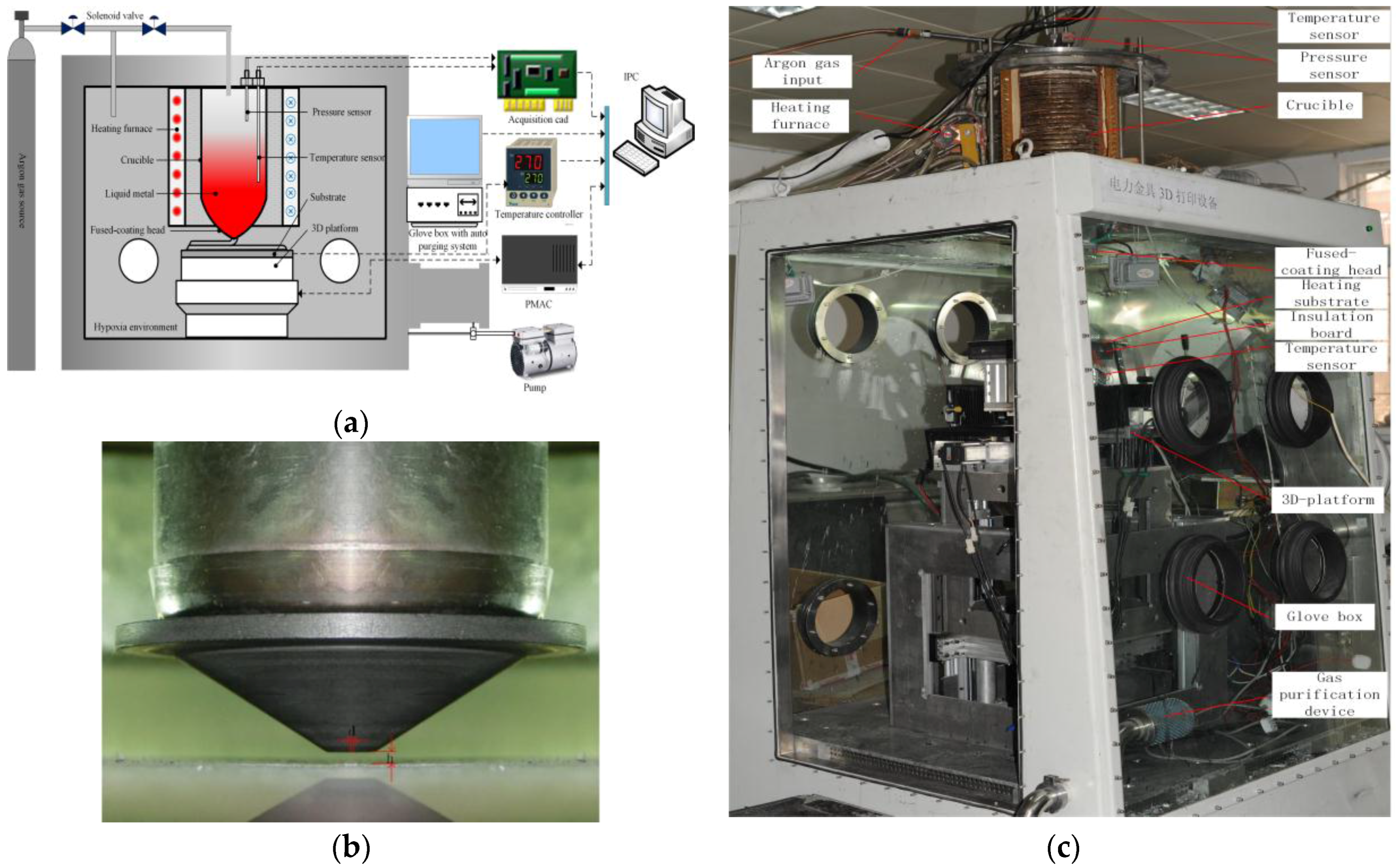
2.1. Experimental System

A schematic illustration of the principle of the MCMAM process and experimental platform is presented in Figure 1a. The equipment of MCMAM includes a pressure control system, an argon gas protection system, and a machine control system on the basis of a movable platform. In this experiment, the MCMAM was used to form specimens by controlling the motion of the 3D platform in accordance with data information. The 3D platform system has a PMAC (programmable multi-axis controller). Under the combined action of gas pressure, hydrostatic pressure, and surface tension, the molten metal flows through the channel in the fused-coating head, as shown in Figure 1b,c.

2.2. Arrangement of the Experiments

To evaluate the feasibility and the control parameters of the designed experiment, a Sn63Pb37 alloy was involved in this work. According to actual situation, the crucible temperature was heated to 270 °C, the initial distance between the micro-coating nozzle and the substrate was set to 1.6 mm, the substrate temperature was set to 90 °C, and the argon mass flowmeter pressure was set to 100 KPa. Single-layer single pass (SLSP) experimental conditions are shown in Table 1.

3. Results and Discussion

As a basic unit, the forming process of a single-track specimen should be primarily investigated. There are many process parameters in the MCMAM forming process, including the deposition velocity, the flow rate, the distance from the nozzle to the workpiece, the heating temperature, the nozzle size, and the heat dissipation conditions, having great impacts on the final forming quality of specimens. The present paper focuses on the deposition velocity, the flow rate, and the layer thickness; thus, other factors are kept constant.

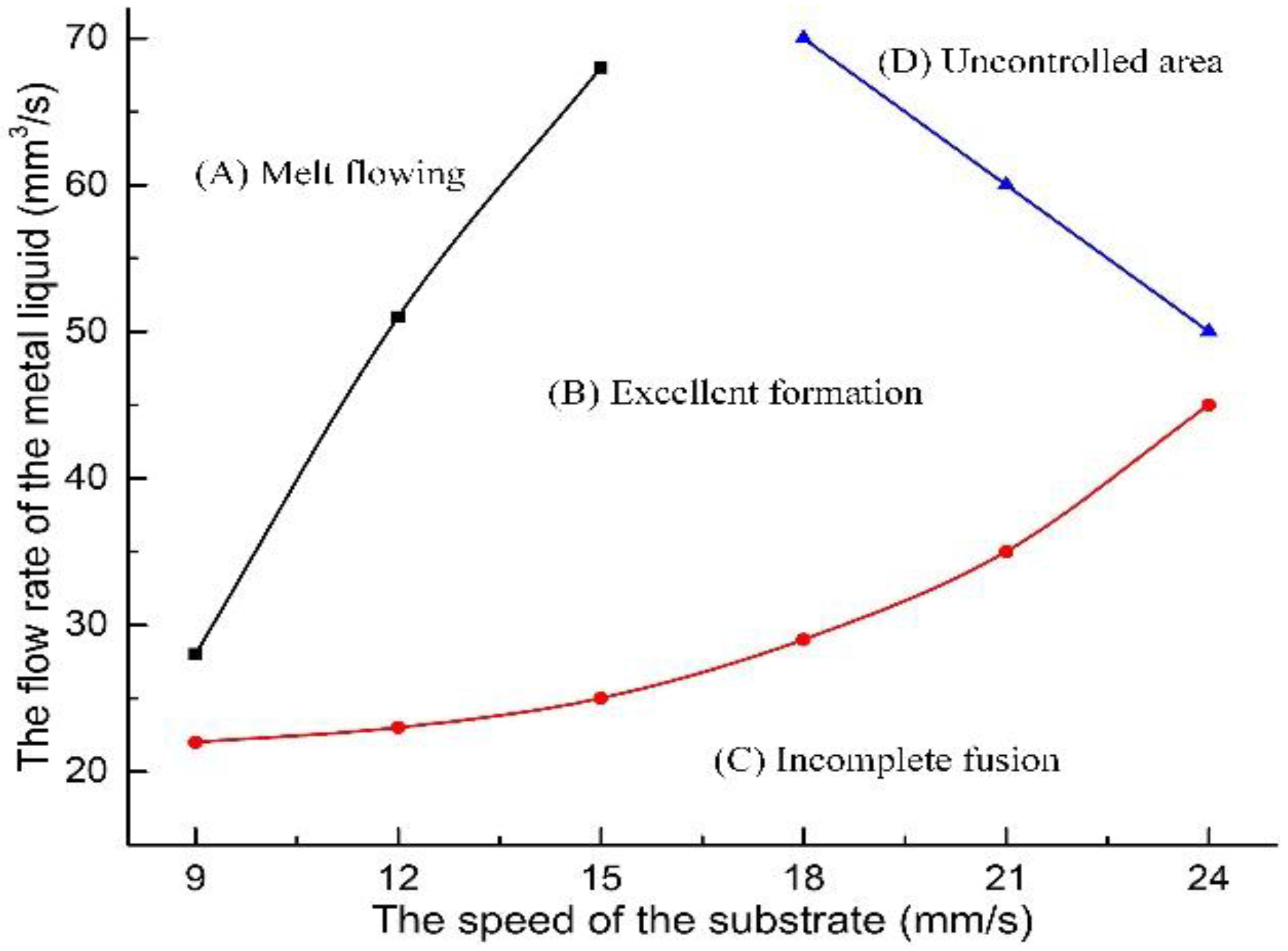
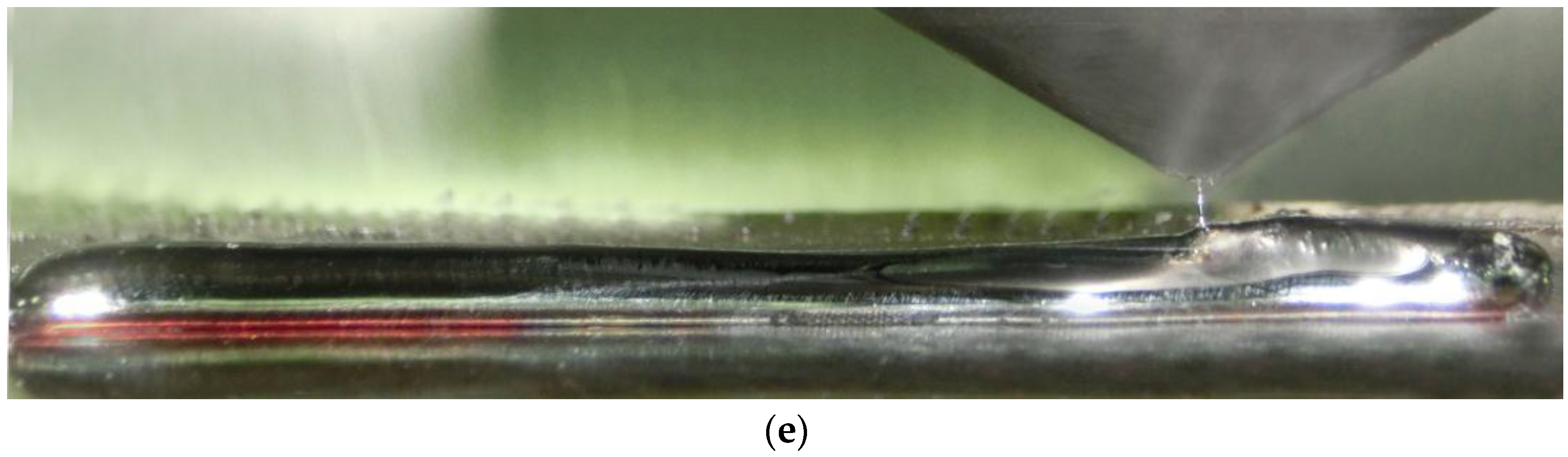
3.1. Preliminary Experiments to Determine the Process Window of SLSP

In this section, the effect of flow rate and deposition velocity on the forming morphology is explored. The flow rate varied from 20 to 70 mm3/s, and the deposition velocity varied from 9 to 24 mm/s. According to the parameters presented in Table 1, a set of preliminary experiments had been conducted. Moreover, the SLSP combination was evaluated according to the surface morphology and the relationship between the process parameters and the forming morphology of SLSP were analyzed, the results of which can be found in Figure 2.
The process parameters were divided into four categories. With a relatively low deposition velocity and high flow rate, Category A can easily cause an accumulation of the melt because the feeding speed of the melt is too high for the given deposition velocity, leading to a significant increment of the micro-coating width and an accumulation of molten metal at the starting and stopping of the SLSP. These problems remain unfavorable to the successful operation of the multilayer single-pass (MLSP) process. As a result, the forming efficiency was low, as shown in Figure 3a. For Category C, with a high deposition velocity and a low flow rate, the molten metal dragged due to surface tension, which caused necking. The position of necking leads to a decrease in mechanical properties in SLSP. The subsequent experiments in Region C were consequently discarded, as presented in Figure 3c. For Category D, with a high flow rate and deposition velocity, micro vibration occurred in the 3D-platform. Hence, the forming defects were aggravated, resulting in burr and distortions, as shown in Figure 3d. For Category B, the flow rate matched well with the deposition velocity, and the surface quality was satisfactory, as shown in Figure 3b.

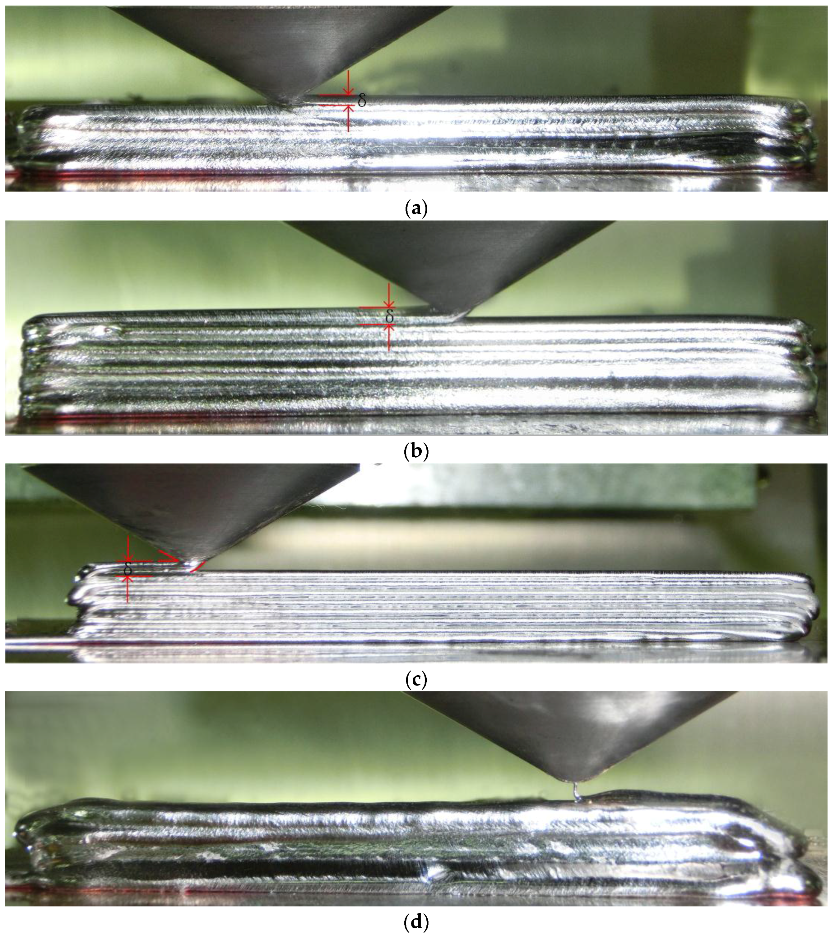
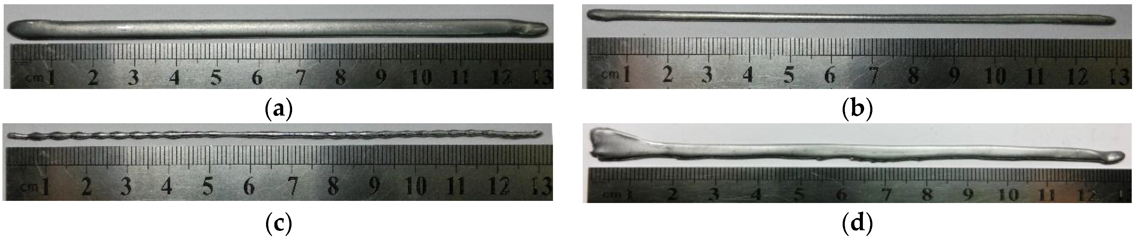
3.2. Influence of the Distance between the Nozzle and the Top Surface of the Previous Layer

In this section, only the layer thickness is discussed in order to maintain other parameter consistency. One goal of this experiment was to achieve multilayer deposition. After one layer was deposited, the platform was moved downward for a distance in the z-direction, and another layer was deposited over the previous one. The forming process of the MLSP is more complicated than the SLSP due to the complex morphologies of the pre-deposited layer. In this section, the forming process is based on the optimized process windows of the SLSP. Each thin-walled specimen has twelve layers that are 100 mm in length. If the forming defect occurs in the current layer, the forming process must be terminated.
The process parameters of Category B in Figure 2 were used. In the experiment, the deposition velocity was 18 mm/s, the flow rate was 50 mm3/s, and the layer thickness was set to 0.9 mm, 1.2 mm, 1.5 mm, 1.8 mm, and 2.1 mm, respectively, the platform was moved downward for a distance in the z-direction. Figure 4 mainly shows the experimental results. As shown in Figure 4a, the nozzle contacted completely with the workpiece when the thickness was 0.9 mm, resulting in wider layers, which was beneficial for the formation of a new layer, as good bonding quality can be achieved between layers. As shown in Figure 4b, when the thickness was 1.2 mm, the thin-wall was not too wide with heat capillary flow pressure and heat capillary flow, resulting in the most complex forming state. As shown in Figure 4c, the molten metal generated a drag angle when the thickness was 1.5 mm, which will be discussed in detail in the next section. As shown in Figure 4d, when the thickness was 1.8 mm, the random jet from the molten metal affected the forming morphology, which led to the failure of the subsequent deposition process. As shown in Figure 4e, the nozzle separated completely from the workpiece when the thickness was 2.1 mm. In addition, the high-speed melt had a strong impact on the free surface of the melt.
To conclude, layer thickness is one of the major factors influencing the forming morphology. Different layer thicknesses will produce a compression or a jet. When the layer thickness is larger than 1.5 mm, the molten metal jet will negatively affect the free surface of the melt, usually causing damage to the previous layers or massive overflowing. When the layer thickness is smaller than 1.2 mm, the width of thin-wall specimens increases due to the nozzle extrusion pressure and, as a result, usually reduces the forming efficiency. The flat forming morphology can be achieved when the layer thickness is between 1.2 mm and 1.5 mm.
The forming morphology of the workpieces in Figure 4b,c are better than the others. Consequently, the process parameters of these two workpieces were applied to form a thin wall, as shown in Figure 5. In Figure 5a, the previous several layers were deposited with a good overlapping rate. However, the cumulative error made the bonding quality decrease, and the porosity increased during the subsequent depositions when the thickness was 1.5 mm. In Figure 5b, the layer thickness matches well with the height of the actual specimens. The ideal workpiece was obtained without any defects, and the morphology of each layer was uniform when the thickness was 1.2 mm.

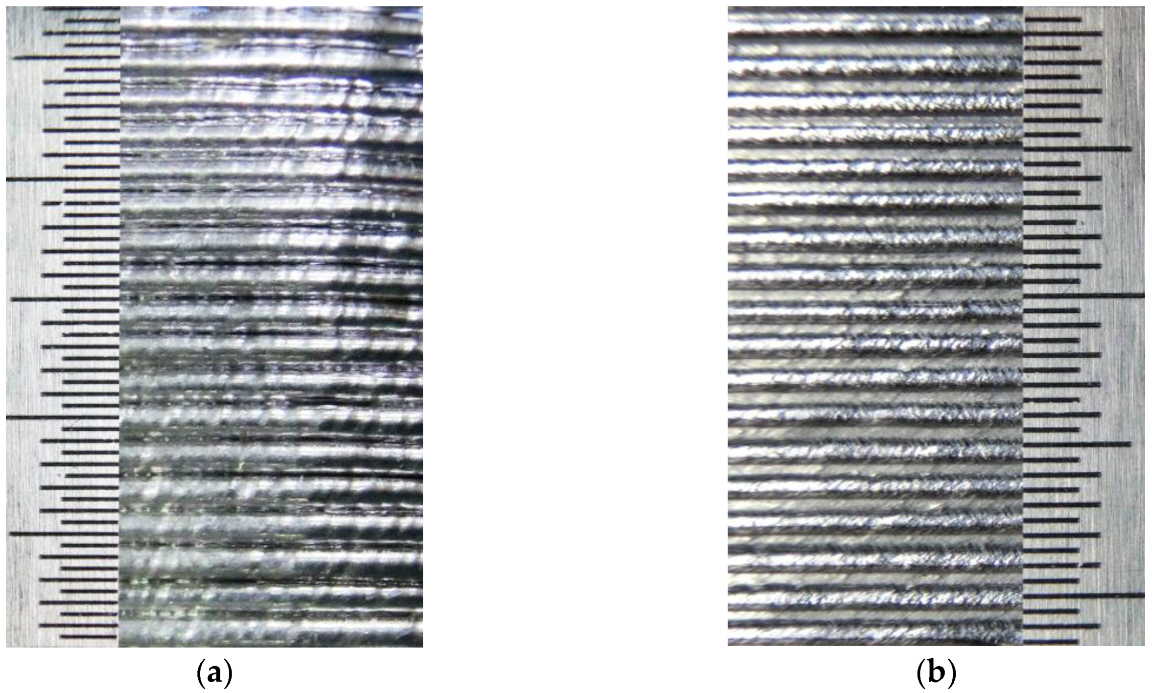
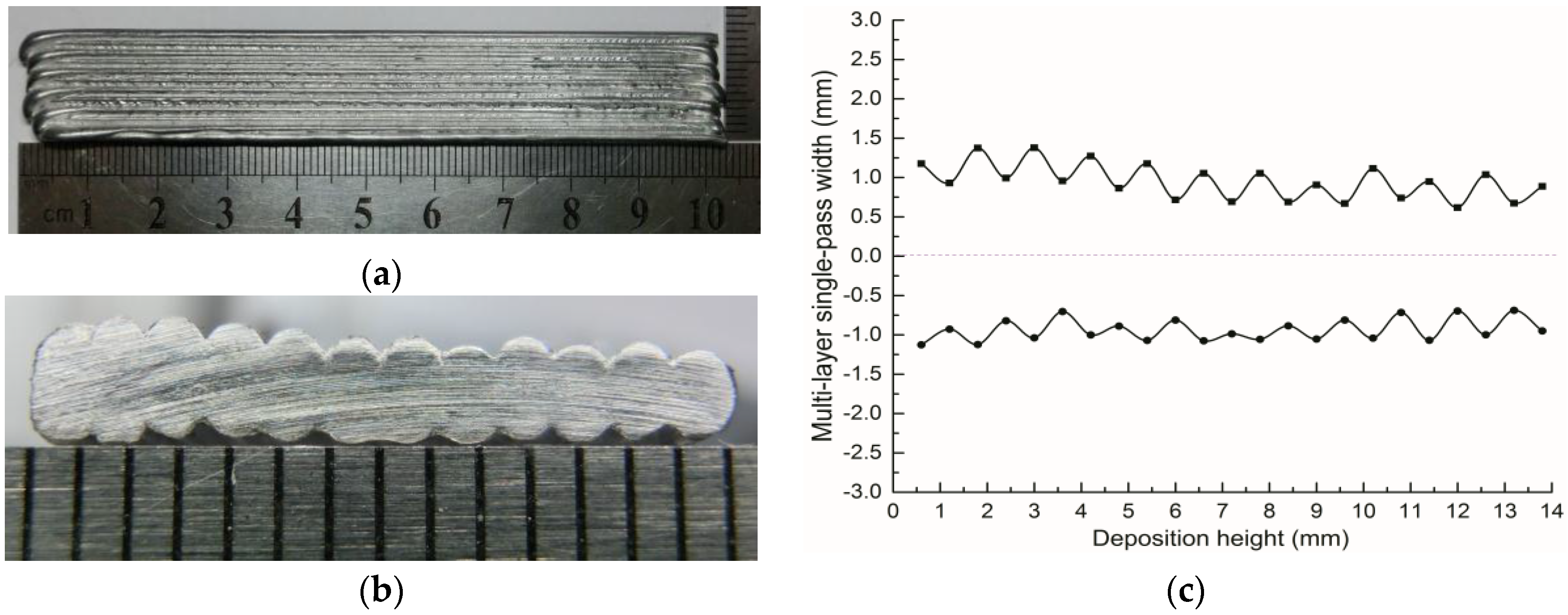
3.3. Waviness and Cross-Section Morphology Analysis of Thin-Walled Specimens

The layer thickness and surface quality remain the most important issues to be taken into consideration for the thin-walled experiments. The waviness was applied to evaluate the surface quality, including three major indexes (Wa, Wq and Wz). The indexes, Wa, Wq, and Wz, denote the arithmetical mean deviation of the assessed profile, the root mean square deviation of the assessed profile, and the maximum height of the assessed profile, respectively. In addition, it was found that the waviness of the formed specimens is greatly affected by the layer thickness. As illustrated in Figure 6a, the thin-walled specimen was formed based on the following process parameters: a deposition velocity of 18 mm/s, a flow rate of 50 mm3/s, and a layer thickness of 1.2 mm. The cross section of the specimen is shown in Figure 6b, and the corresponding measured data was shown in Figure 6c. The waviness indexes were analyzed, and the results are as follows: Wa = 0.9448, Wq = 0.963, and Wz = 0.303.

4. Conclusions

To conclude, a new metal 3D printing process—micro-coating metal additive manufacturing (MCMAM)—was investigated in this paper. The forming morphologies of the deposited thin-walled specimens were analyzed, and the main findings are summarized as follows:
  • The MCMAM technology is considered an economical and effective forming process. The forming efficiency of the MCMAM up to 50 mm3/s (viz. 1490 g/h) is doubled, compared to the metal droplet deposition.
  • The layer thickness is one of the major factors, influencing the forming morphology. The forming morphology of the thin-wall specimen is relatively the best when the layer thickness is set to 1.2 mm, and the metallurgical bonding of the adjacent layers can be obtained.
  • The waviness was used to analyze the forming morphology of the thin-walled specimen. The values of the surface waviness indexes are Wa = 0.9448, Wq = 0.963, and Wz = 0.303 when the layer thickness is 1.2 mm.

Acknowledgments

Project supported by the State Key Development Program Research of China (2016YFB1100400), the national project (20140530) “3D Printing Electrical Fittings Droplet Forming and Shaping the Experimental Prototype Development Platform”, the China Postdoctoral Science Foundation (2014m560764) “Study on Metal Micro Jet Droplet Electromagnetic Confinement Deposition Forming Mechanism” and the Fundamental Research Funds for the Central Universities (xjj2016124).

Author Contributions

Jun Du and Zhengying Wei conceived and designed the experiments; Xin Wang, Xuewei Fang, and Guangxi Zhao performed the experiments; Hao Bai and Wei Liu analyzed the data; Chuanqi Ren and Yunfei Yao contributed reagents/materials/analysis tools; Xin Wang wrote the paper.

Conflicts of Interest

The authors declare no conflict of interest.

References

  1. Beaman, J.J.; Deckard, C.R. Selective Laser Sintering with Assisted Powder Handling. U.S. Patent 4938816, 1990. [Google Scholar]
  2. Arcella, F.G.; Froes, F.H. Producing titanium aerospace components from powder using laser forming. JOM 2000, 52, 2–30. [Google Scholar] [CrossRef]
  3. Clare, A.T.; Chalker, P.R.; Davies, S.; Sutcliffe, C.J.; Tsopanos, S. Selective laser melting of high aspect ratio 3D nickel–titanium structures two way trained for MEMS applications. Int. J. Mech. Mater. Des. 2008, 4, 181–187. [Google Scholar] [CrossRef]
  4. Aiyiti, W. Investigation of the overlapping parameters of MPAW-based rapid prototyping. Rapid Prototyp. J. 2006, 12, 165–172. [Google Scholar] [CrossRef]
  5. Xiong, J.; Zhang, G.; Zhang, W. Forming appearance analysis in multi-layer single-pass GMAW-based additive manufacturing. Int. J. Adv. Manuf. Technol. 2015, 80, 1767–1776. [Google Scholar] [CrossRef]
  6. Heralic, A.; Christiansson, A.K.; Ottosson, M.; Lennartson, B. Increased stability in laser metal wire deposition through feedbackfrom optical measurements. Opt. Lasers Eng. 2010, 48, 478–485. [Google Scholar] [CrossRef]
  7. Xiong, J.; Zhang, G. Adaptive control of deposited height in GMAW-based layer additive manufacturing. J. Mater. Process. Technol. 2014, 214, 962–968. [Google Scholar] [CrossRef]
  8. Mireles, J.; Espalin, D.; Roberson, D.A.; Zinniel, B.; Medina, F.; Wicker, R. Fused Deposition Modeling of Metals. In Proceedings of the Solid Freeform Fabrication Symposium, Austin, TX, USA, 6–8 August 2012; pp. 836–845.
  9. Yao, Y.; Gao, S.; Cui, C. Rapid prototyping based on uniform droplet spraying. J. Mater. Process. Technol. 2004, 146, 389–395. [Google Scholar]
  10. Du, J.; Wei, Z.; Wang, X.; Fang, X.; Zhao, G. A novel high-efficiency methodology for metal additive manufacturing. Appl. Phys. A 2016, 122, 945. [Google Scholar] [CrossRef]
Figure 1. (a) Molten metal micro-coating equipment schematic diagram. (b) Nozzle practicality picture. (c) Molten metal micro-coating equipment practicality picture.
Metals 06 00313 g001
Figure 2. Process parameter set of various forming morphology in a single-layer single pass (SLSP).
Metals 06 00313 g002
Figure 3. Various forming morphology with different combinations of process parameters. (a) Melt flowing. (b) Excellent formation. (c) Incomplete fusion. (d) Uncontrolled area.
Metals 06 00313 g003
Figure 4. The deposited specimens in different layer thickness. (a) δ = 0.9 mm. (b) δ = 1.2 mm. (c) δ = 1.5 mm. (d) δ = 1.8 mm. (e) δ = 2.1 mm.
Metals 06 00313 g004aMetals 06 00313 g004b
Figure 5. The deposited specimens in different layer thickness. (a) δ = 1.5 mm. (b) δ = 1.2 mm.
Metals 06 00313 g005
Figure 6. Thin wall with a 1.2 mm layer thickness for each layer: (a) Main view. (b) Cross-section view. (c) Cross-section data statistics.
Metals 06 00313 g006
Table 1. Experimental condition of micro-coating metal additive manufacturing (MCMAM).
Property and ParameterValue
Coating head temperature270 °C
Heating substrate90 °C
Argon mass flowmeter20–70 mm3/s
Deposition velocity9–24 mm/s
Initial distance1.6 mm
Layer thickness0.9–2.1 mm
Coating nozzle0.3 mm
Pressure100 KPa
Glove boxAr (99.999%) (20 ppm)
Size of copper-clad substrate300 mm × 200 mm × 10 mm
SLSP deposited length130 mm
multilayer single pass deposited length100 mm

