Article

Effect of Surface States on Joining Mechanisms and Mechanical Properties of Aluminum Alloy (A5052) and Polyethylene Terephthalate (PET) by Dissimilar Friction Spot Welding

by
Farazila Yusof
1,2,*,
Mohd Ridha bin Muhamad
1,2,
Raza Moshwan
1,2,
Mohd Fadzil bin Jamaludin
1,2 and
Yukio Miyashita
3
1
Department of Mechanical Engineering, University of Malaya, Kuala Lumpur 50603, Malaysia
2
Centre of Advanced Manufacturing and Material Processing, University of Malaya, Kuala Lumpur 50603, Malaysia
3
Department of System Safety, Nagaoka University of Technology, Nagaoka 940-2188, Japan
*
Author to whom correspondence should be addressed.
Metals 2016, 6(5), 101; https://doi.org/10.3390/met6050101
Submission received: 10 February 2016 / Revised: 14 March 2016 / Accepted: 18 March 2016 / Published: 28 April 2016
(This article belongs to the Special Issue Aluminum Alloys)

Abstract

:
In this research, polyethylene terephthalate (PET), as a high-density thermoplastic sheet, and Aluminum A5052, as a metal with seven distinct surface roughnesses, were joined by friction spot welding (FSW). The effect of A5052’s various surface states on the welding joining mechanism and mechanical properties were investigated. Friction spot welding was successfully applied for the dissimilar joining of PET thermoplastics and aluminum alloy A5052. During FSW, the PET near the joining interface softened, partially melted and adhered to the A5052 joining surface. The melted PET evaporated to form bubbles near the joining interface and cooled, forming hollows. The bubbles have two opposite effects: its presence at the joining interface prevent PET from contacting with A5052, while bubbles or hollows are crack origins that induce crack paths which degrade the joining strength. On the other hand, the bubbles’ flow pushed the softened PET into irregularities on the roughened surface to form mechanical interlocking, which significantly improved the strength. The tensile-shear failure load for an as-received surface (0.31 μ m Ra) specimen was about 0.4–0.8 kN while that for the treated surface (>0.31 μ m Ra) specimen was about 4.8–5.2 kN.

1. Introduction

To solve environmental and energy problems, light materials are increasingly being adopted as structural constituents in different transportation industries, such as the automotive, aeronautic and train industries. The various parts of light materials are combined and joined to assemble such structures and components for cars, airplanes and trains. There are several joining technologies [1] including welding, bolt joining adhesive joining, and so on. Tungsten inert gas (TIG) welding and laser welding are commonly used to join similar and dissimilar light metal sheets.
Friction stir welding (FSW) has been recently developed and successfully applied to join light materials such as aluminum alloys and titanium alloys. The welding method is a promising ecological welding method that enables workers to diminish material waste and avoid radiation and harmful gas emissions that often occur from fusion welding [2,3]. The main process parameters in controlling the quality of joints are tool rotation speed, tool traverse speed, vertical pressure on the specimen, the tilt angle of the tool, tool geometry, and others [4,5]. During welding, a non-consumable tool attached with a specially designed pin rotates and pushes the butting edges of the two plates to be joined. The friction heat causes the material to soften, allowing the tool to penetrate into the material surface. The tool shoulder sits on the specimen’s surface during penetration. Under this condition, the rotating tool traverses along the joining line. Thus, generated frictional heat causes both materials to soften under the tool where joining is achieved. This process is suitable for joining plates and sheets. However, it can also be employed for joining pipes and hollow sections [6]. Although the FSW process was initially developed for aluminum alloys [7,8,9], it also has a great potential for the welding of copper [10], titanium [11], steel [12], magnesium [13], metal matrix composites [14], and different material combinations [15].
Recently, studies have shown that applying FSW welding to thermoplastics is successful and various factors influencing its joinability were investigated. The effect of tool tilt angle and welding speed on the tensile strength in FSW of polyethylene [16] was studied using different tool dimensions and pre-heated pins [17]. Taguchi’s approach to parameter design and analysis of variance were utilized with further experimental confirmation for FSW of polyethylene. It was shown that the optimum welding parameters were tool rotational speed of 3000 rpm, traverse of 115 mm/min and tilt angle of three degrees [18]. In a novel study by Vijendra, a new hybrid friction stir welding process, i-FSW, was designed. In i-FSW, the tool is heated during welding by an induction coil, and the temperature is precisely maintained through feedback control [19]. Another study on tool design where a new self-reacting tool with a convex pin was utilized showed the greatest effects on tensile strength in welding of acrylonitrile butadiene styrene (ABS) sheets [20]. Recent research that combines experimental and analysis models for optimization is popular to reduce experimental cost and for the ability to predict optimal conditions precisely. Factors that influence FSW were optimized using a factorial design and analyzed using Artificial Neural Networks (ANN) to compare the experimental and the model analysis, which has demonstrated that tool plunge rate, dwell time and waiting time, plunging force, and torque were discussed as the most influential factors [21,22]. A study of an ABS sheet optimized by Analysis of Variance (ANOVA) and Response Surface Methodology (RSM) demonstrated high diameter ratio and low rotational speed, which are optimal. A comparison indicated the more accurate prediction of a corresponding model for a conical pinned tool than a cylindrical probe tool. The recommended conditions identified are two degrees for tilt angle, 900 rpm rotational speed, a tool with diameter ratio of 20/6 and linear speed of 25 mm/min, which generated a weld joint with equal yield strength to the base material [23]. In another study, Simoes analysed the material flow and thermo-mechanical phenomena taking place during FSW of polymers. Polymethylmethacrylate (PMMA) was used owing to the high transparency so that polarization during tool penetration could be observed clearly. It has been reported that due to the polymers’ rheological and physical properties, the thermo-mechanical conditions during FSW are very different from those registered during the welding of metals. The material flow and temperature distribution between metallic and polymeric materials were compared based on the Arbegast flow-partitioned deformation zone model for FSW in metals. The formation of discontinuities was indicated as one of the main weldability problems for polymers [24].
There are very few reports on the friction stir spot welding of polymer-polymer as well as polymer-metal combinations, which have great applicability and are in high demand, especially in the automotive industry [25,26]. In the author’s previous work [27], the dissimilar joining of aluminum alloys (A5052) and polyethylene terephthalate (PET) was attempted using the frictional energy generated from friction spot welding. In the joining conditions shown for plunge depth of 0.7 mm, the lower plunge speed exhibited higher tensile strength, which was the result of longer contact time and more generated heat. The process yielded the dissimilar joining of the two materials despite the low joining strength. In the dissimilar friction stir butt joining of aluminum and Polycarbonate (PC), the feasibility was achieved, but the concerns remain regarding lower tensile strength due to fracture induced voids [28]. The dissimilar joining of aluminum and thermoplastics by adopting the hole-clinching method has been reported in several studies. Lee investigated tool shapes such as punch diameter, punch corner radius and die depth on hole-clinching for dissimilar materials [29]. Studies on the joinability of rigid thermoplastic polymers with aluminum AA6082-T6 alloy sheets by mechanical clinching have revealed that fracture at the metal or polymer sheet was the main factor contributing to unsuccessful joinability. Joinability has been examined by studying mechanical interlocking manipulated by tool geometry [30], tool shapes [31] or temperature [32]. These studies focused on tool shapes that directly influence mechanical interlocking at the microstructural level. An analysis study by Wirth on the bonding behavior and joining mechanism of aluminum and thermoplastics recommended optimal conditions such as holding time, axial force, etc. [33]. High lap joint quality with shear strength of 5–8 MPa was reported in a case study of aluminum and laser transmission joints of nylon [34] and PMMA [35] where in both cases the temperature reached the melting temperature of the thermoplastics.
In the present study, the effect of surface roughness on the joining strength of an FSW-ed PET-A5052 dissimilar joint is investigated with the aim to increase the joining strength. The joining mechanism and effects of surface roughness are discussed in detail.

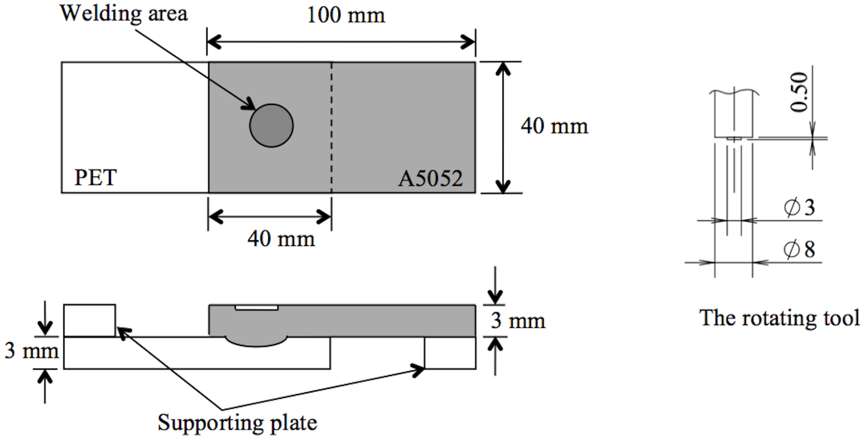
2. Materials and Methods

Aluminum alloy (A5052) and polyethylene terephthalate (PET) specimens were machined to dimensions of 40 × 100 mm and 3 mm thickness. The chemical composition of A5052 is shown in Table 1. The physical and mechanical properties of A5052 and PET are shown in Table 2. The aluminum alloy A5052 specimens were prepared in the as-received condition, and six different surface roughness values were prepared by wire brushing and etching (Etchant: Hydrochloric acid and Aluminium chloride), as shown in Table 3. The surface roughness of the A5052 specimens was measured by means of a profilometer (Mitutoyo, Kawasaki, Japan, Model: SJ-201) with a diamond stylus. The arithmetic mean surface roughness values, Ra, obtained by averaging three measurements for each specimen are shown in Table 3. In this study, a lap joint arrangement is investigated, with an A5052 specimen positioned on top and a PET specimen on the bottom.
Figure 1 displays the schematic diagram of lap joint specimen positioning (left) and rotating tool dimensions (right). The dark region at the center of the assembly represents the welding area. Two alignment pads with 3 mm thickness were attached to the end of the joint specimens to align the specimens on the machine. The rotating tool consists of a shoulder with 8 mm diameter and a conical center probe with 3 mm diameter. In the FSW process, the rotating tool partially penetrated the A5052 surface to a certain depth and then moved up after a dwell time of 2 s. Table 4 lists the welding parameters, including rotating speed, plunge speed, plunge depth and dwell time. A single lap shear test of the FSW joints was performed using a tensile test machine (Shimadzu, Kyoto, Japan, Model: AGS-X, 10 kN) with a loading rate of 0.5 mm/min. Scanning electron microscope (SEM) were used to study and observe the micro-structural interlocking, joining structure and material flow at cross-sectional of the joint interface.

3. Results and Discussion

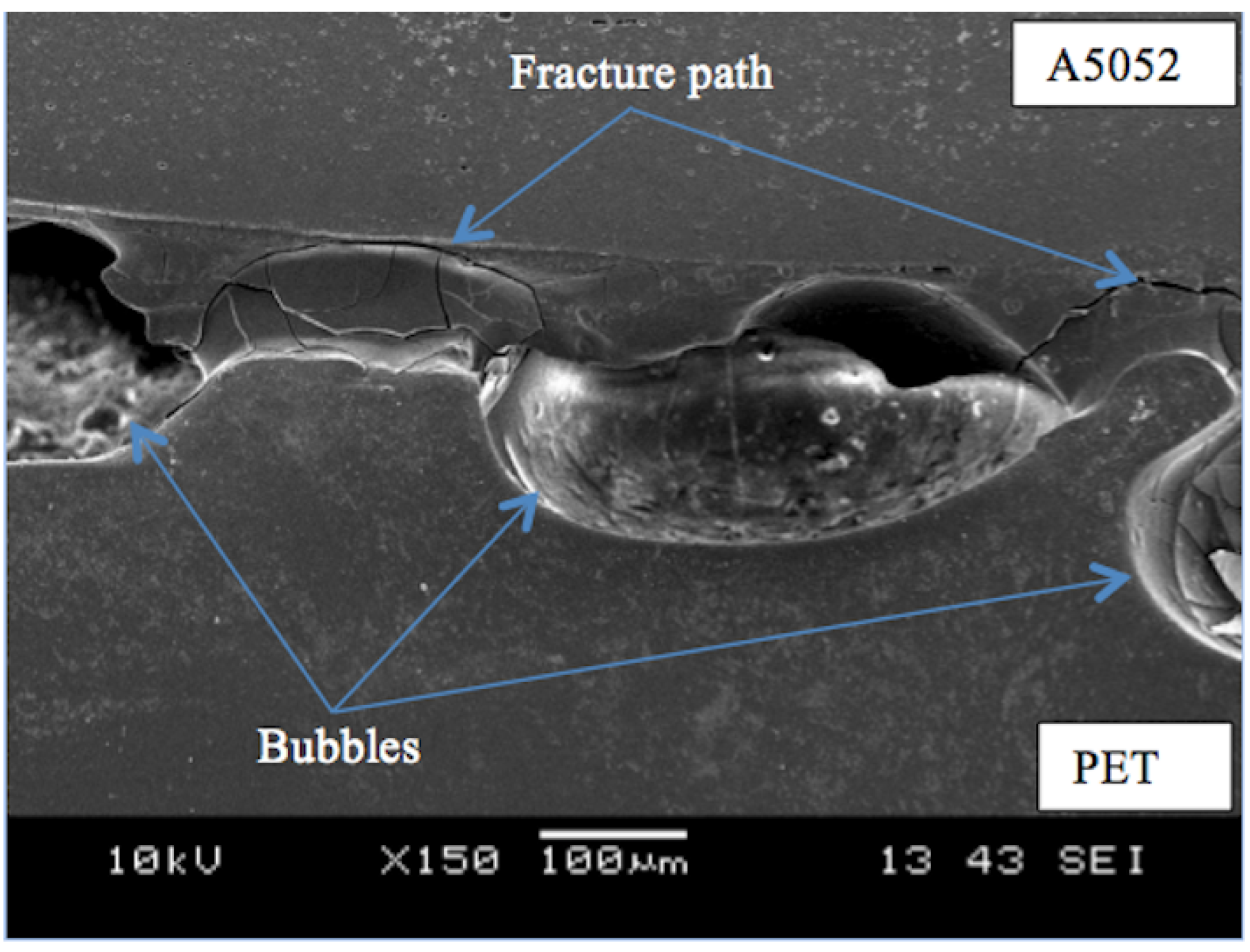
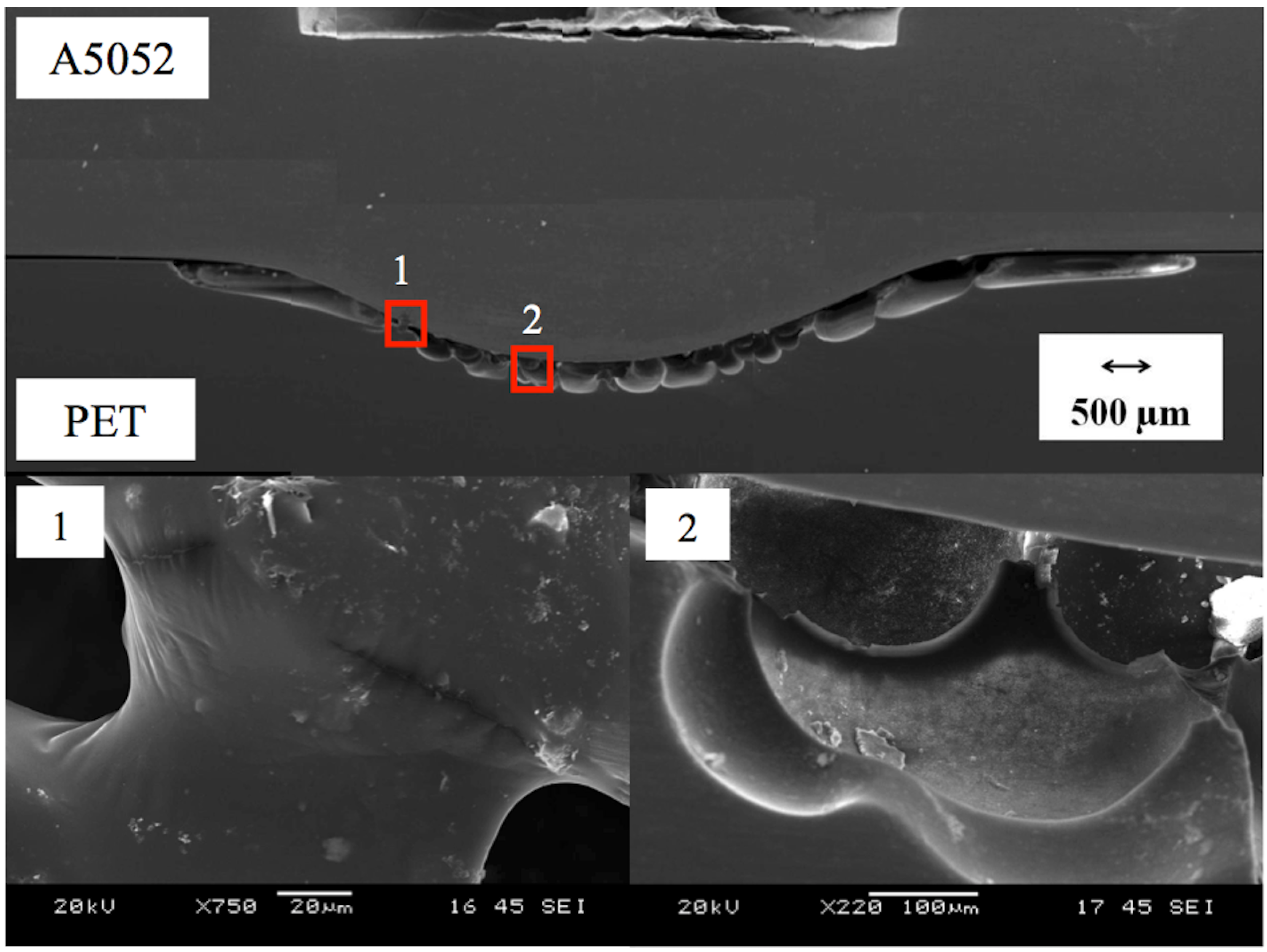
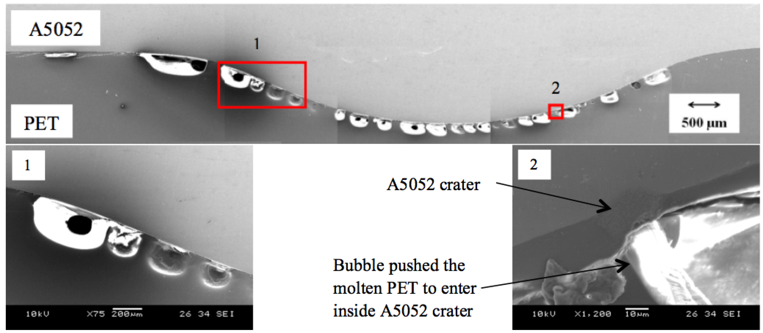
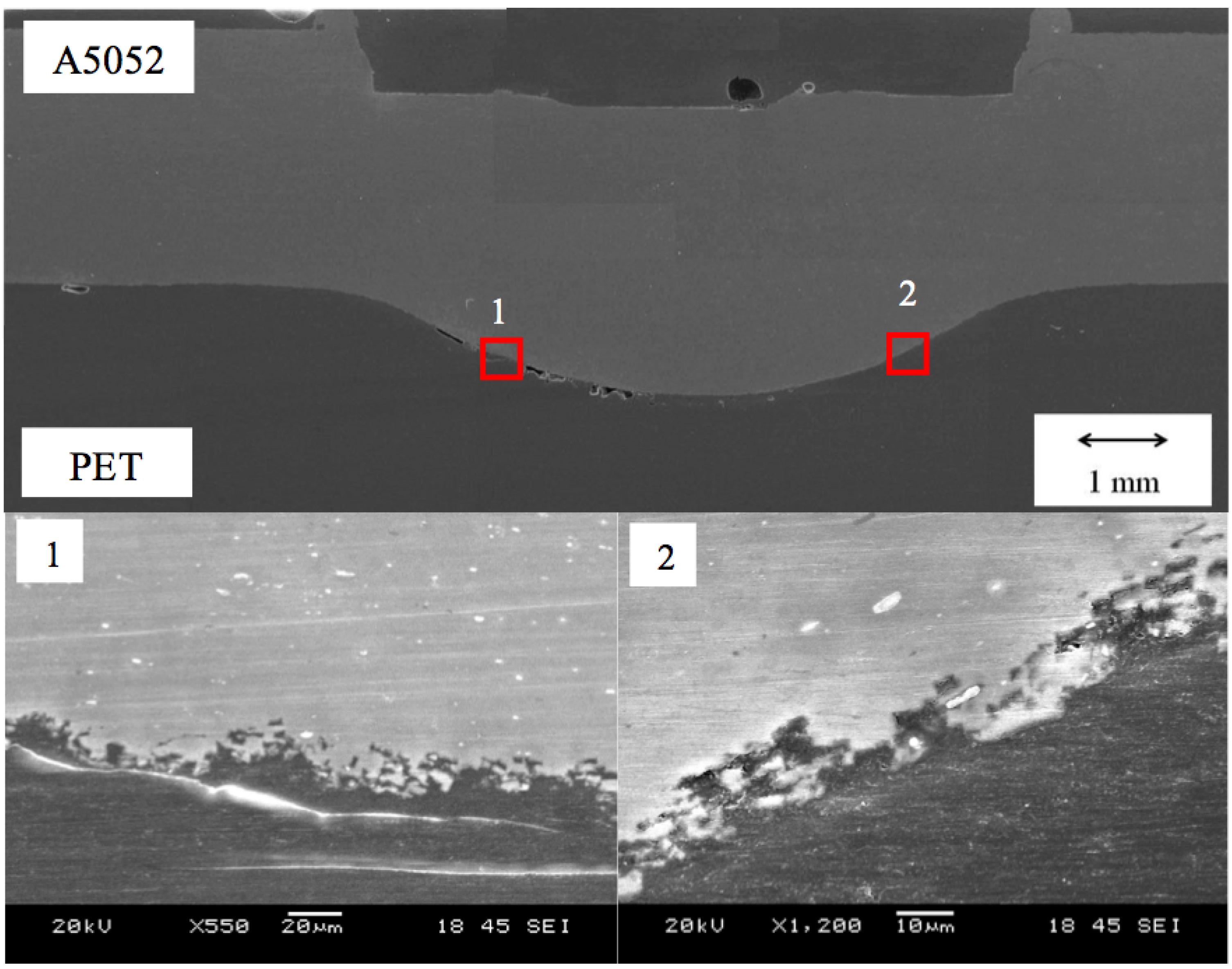
3.1. Joining Mechanism

Adhesion between metal and polymer is a complicated process. Therefore, it is crucial to understand the bonding mechanism between both materials. For polymer and metal interfaces, the principal mechanisms include physical adsorption, mechanical interlocking and chemical adhesion (covalent bonds) [36]. In this study, different surface conditions were utilized in order to improve the adhesive behavior of A5052 and PET. According to Qizhou Yao and Jianmin Qu [37], metal surfaces are microscopically rough. Thus, when a liquid is applied to a rough surface, it conforms to the rough surface and fills the irregularities of the substrate surfaces, such as microgrooves, holes and dips. Similar behavior is predicted during the joining of A5052 and PET.
In specimen preparation, the A5052 surface was roughened by pre-treating. It is believed that higher surface roughness will increase the adhesive properties between two materials [38,39,40]. For A5052-PET joints with treated surface roughness, the PET would soften and conform to the A5052 irregularities, creating an interfacial region. This region would have the intermediate physical properties of PET and A5052. Therefore, higher joining strength is achievable for specimens with higher surface roughness.

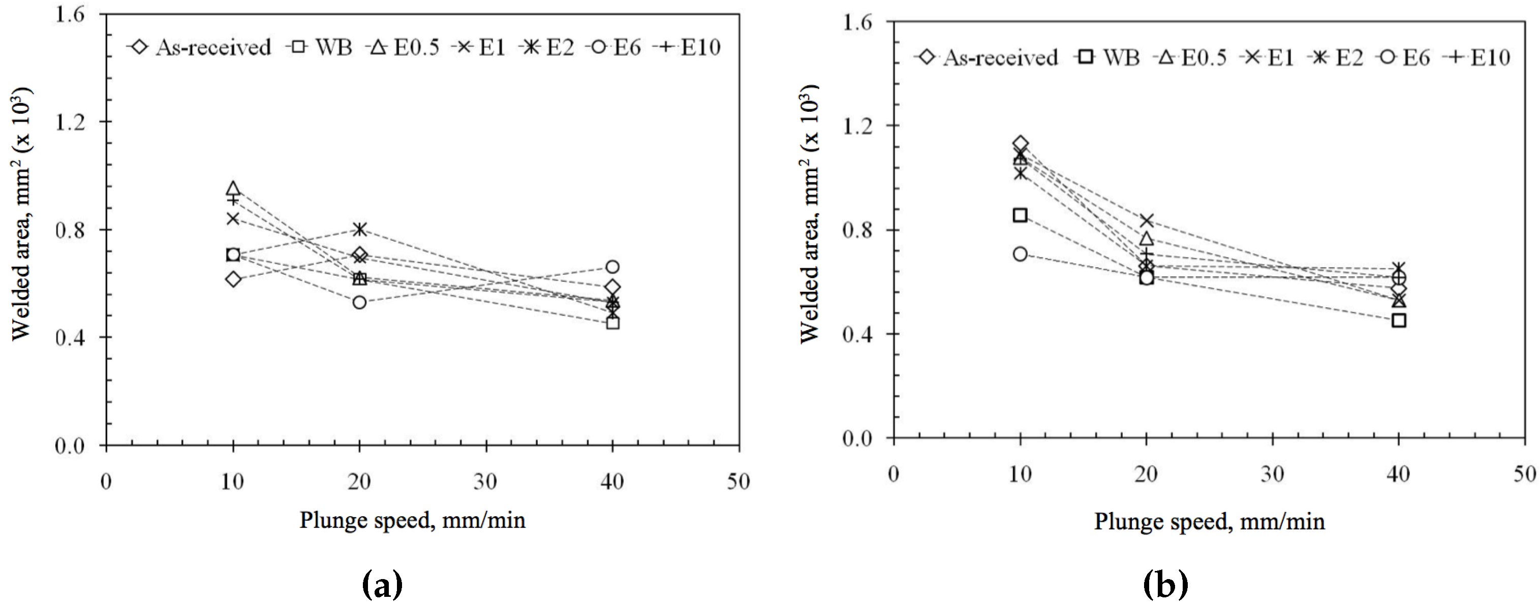
3.2. Effect of Surface Roughness on Welded Area

As mentioned in the previous report [27], the welded area could be clearly observed through the transparent PET side after FSW. In this region, the molten or softened PET is strongly attached to the A5052. In the present study, the welded area was also measured for all FSW joints. The results are presented in Figure 2a,b. The welded area ranged from 450 to 900 mm2 for the specimens welded at a plunge depth of 0.4 mm. For the specimens welded at plunge depth of 0.7 mm, the welded area ranged from 550 to 1100 mm2. Therefore, a larger welded area was obtained for 0.7 mm plunge depth compared to 0.4 mm. It is speculated that the deeper tool penetration generated a greater amount of heat, thus producing a larger welded area. This effect is in line with Oliveira et al.’s report [1] that deeper tool penetration induces high heat input and greater joining strength.
In the current study, it was observed that the joined area of all specimens was larger when welded at lower plunge speed. A lower plunge speed induces substantial heat at the tool tip due to the longer spin duration, hence increasing the joined area. It was also noticed that the joined area for the A5052(AR)-PET joint converged and declined at higher plunge speed, even with the different surface roughness values of the A5052 specimens. This implies that the heat generated from rapid plunge speeds is similar to the variance of pre-treated surface roughness specimens used in the experiment.

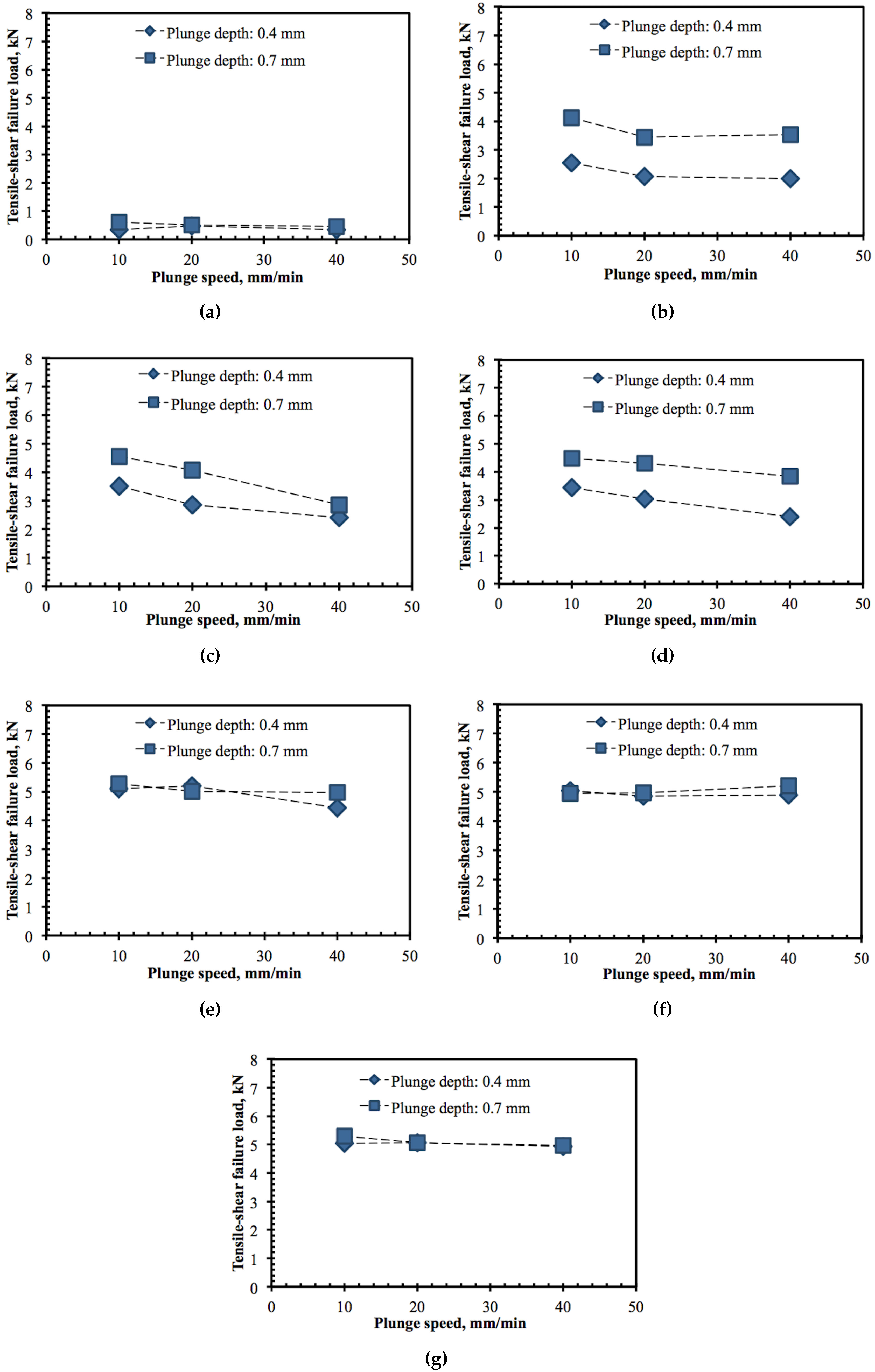
3.3. Effect of Surface Roughness on Tensile-Shear Strength

Figure 3a–g show the relationships between plunge speed and tensile shear failure load for the specimens welded at plunge depths of 0.4 and 0.7 mm, respectively. Although there is a slight decrease in tensile-shear failure load as the plunge speed increases for WB, E0.5 and E1, generally failure load was constant regardless of the plunge speed. Additionally, the plunge depth 0.7 mm yielded greater failure load than 0.4 mm, apparently from more heat induced. The results E2, E6 and E10 exhibited that higher surface roughness produced a higher tensile-shear failure load. Notably at a higher plunge speed, the difference could be significantly observed.
The fracture surface from the single lap shear test provides insight into the behavior of the failure load observed. Figure 4 displays images of fracture surfaces in the single lap shear test. Three types of failures were identified, and it was observed that surface roughness influenced the type of failure in the single lap shear test. Type 1: Failure is caused by separation at the welded interface without damage to the parent materials. It includes the A5052(AR)-PET joint at all plunge depths and plunge speeds, and the A5052(WB)-PET joint at 0.4 mm plunge depth and all plunge speeds. Type 2: Failure starts at the edge of the bubble formation region in the center of the welded area. It includes the A5052(E0.5)-PET and A5052(E1)-PET joints at 10 mm/min plunge speed and at all plunge depths. Type 3: Failure occurs from the edge of the welded area following the large plastic deformation of the PET specimen. It includes the A5052(E6)-PET and A5052(E10)-PET joints at all plunge speeds and plunge depths and the A5052(E2)-PET joint at a plunge depth of 0.7 mm and all plunge speeds. In failure Type 1 (T1), the upper (A5052) and lower (PET) specimens were separated from each other, and no severe damage occurred on either side. For failure Type 2 (T2), the upper and lower specimens were separated from each other, but the lower specimen was broken. For failure Type 3 (T3), the upper and lower specimens did not easily separate, and the lower specimen was elongated before fracturing.
It was found that the tensile shear failure load was relatively low when the fracture was initiated at the interface (Type 1), which is clearly observed on the A5052(AR)-PET joint. It is believed that the joint was weak due to bubble formation. From the fracture path identified, it was found that the path appeared at the edge of the bubbles as observed in Figure 5. This indicates that the bubbles near the joining interface may have induced the fracture and directly affected the joining strength. In addition, the bubbles formed in the A5052(AR)-PET joint were relatively larger than the specimens with treated surfaces. The observation suggests that bubble size affects the failure load. In the case of Type 2 and Type 3, the tensile shear failure load was relatively high, with a number of specimens having reached the maximum load when the fracture was initiated in the PET sheet. However, in Type 3, the PET was elongated, and necking occurred at the PET side near the edge of the joined area. This phenomenon shows that a strong joint was achieved with the materials. Strong interfacial bonding between PET and A5052 was attained due to higher surface roughness treated by etching. Further investigations of the cross-sectional observation at the joined interface could explain these behaviors.
The relationships between plunge speed and shear strength are shown in Figure 6a,b, respectively. The shear strength was calculated from the ratio of shear failure load to joined area. The shear strength for specimens that could not be separated (Type 3) is not included in Figure 6. As seen from Figure 6a,b, the specimens with surface modifications exhibited higher shear strength than the A5052 (AR)-PET joint. The highest shear strength of 9.03 MPa was achieved for the A5052(E2)-PET joint (2 min etching, 40 mm/min plunge speed, and 0.4 mm plunge depth). The joined specimens with etching-roughened surfaces had higher surface roughness than A5052(AR).
Therefore, stronger interfacial bonding between A5052 and PET occurred, thus improving the shear strength. The molten PET flows into irregularities such as pores, holes and crevices due to the pushing of bubbles’ internal pressure. This phenomenon effectively conforms PET to the surface. Further investigation of the joined interface cross section could clarify the mechanical interlocking effect. It was also observed that the shear strength increased with increasing plunge speed. Similarly, plunge speed has a pushing effect or impact on the molten PET flow, which promotes the mechanical interlocking of materials.

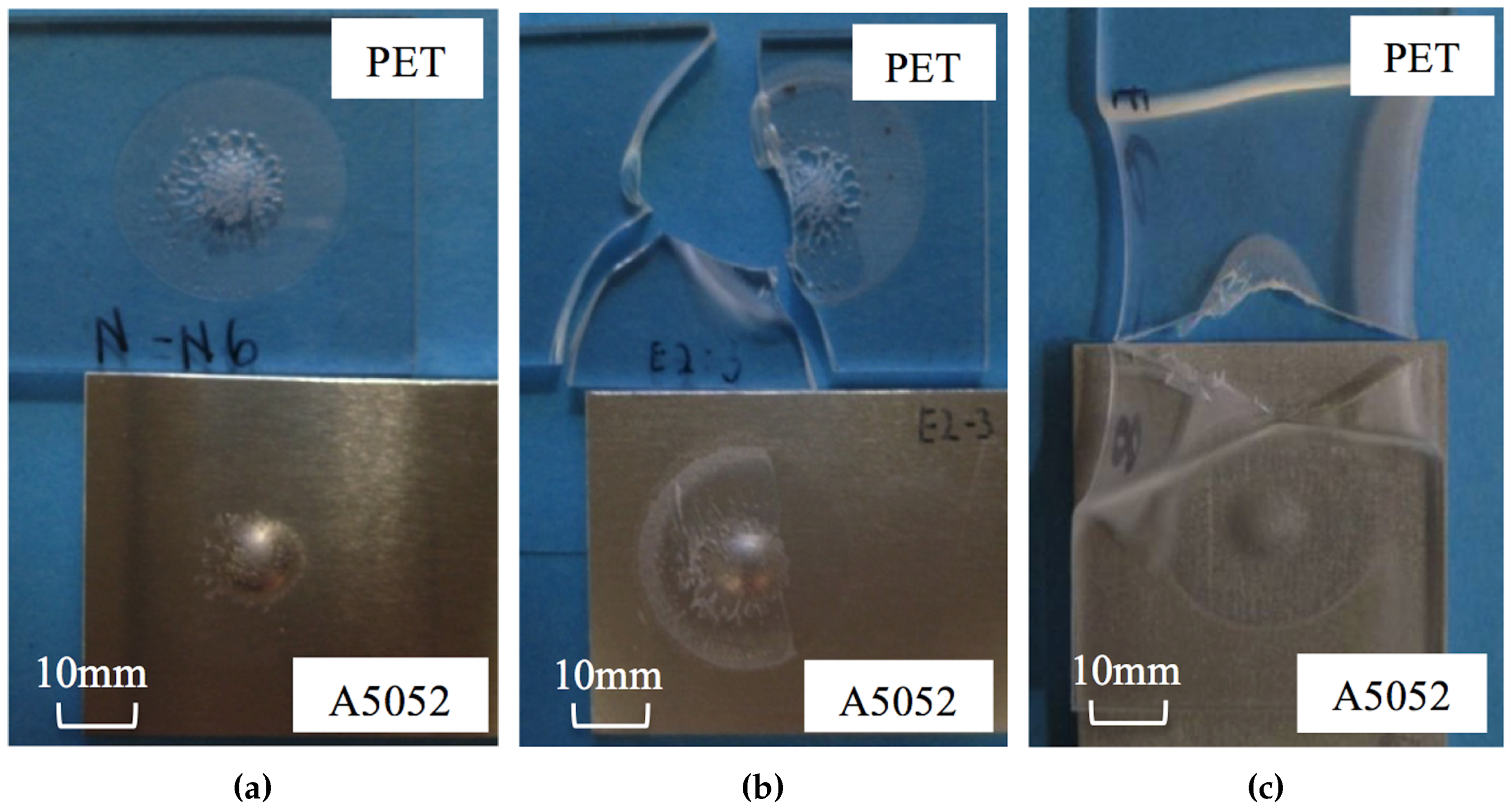
3.4. Cross-Sectional Observations of the Joined Interface

Cross-sectional observations of the joined regions for three typical joint specimens corresponding to Types 1, 2 and 3 are shown in Figure 7, Figure 8 and Figure 9, respectively. Figure 7 indicates significant bubble formation with a maximum bubble size of approximately 1 mm in the center region of the welded area in the A5052(AR)-PET joint with surface roughness of 0.31 μ m Ra. These bubbles formed from evaporated PET due to heat generated by the tool. The high internal pressure in the bubbles drove the molten PET into the aluminum surface irregularities, as seen in the first region in Figure 7. However, these large bubbles induced fractures and thus degraded the failure strength of the joined interface. Here, the material flow initiated by the protruded part of the aluminum towards the PET. The heat is transferred by conduction, softens the PET and dislocates it away from the plunged area. As it cools, the PET shrinks towards the plunge area simultaneously adhered to the rough aluminum surface by formed mechanical interlockings.
For the Type 2 specimens with surface roughness of 0.47 and 0.61 μ m Ra, the size and number of bubbles were smaller compared to the Type 1 specimen, as seen in Figure 8. Therefore, the tensile shear failure load for Type 2 was higher than for the Type 1 specimen. For the Type 3 specimens with surface roughness of 1.42, 3.41 and 4.16 μ m Ra, the size and number of bubbles were much smaller compared to the Type 1 and 2 specimens, as seen in Figure 9. It was observed that the molten PET flowed into the craters of the A5052 roughened surface. During tool penetration, the molten PET conformed to the rough surface and filled up the irregularities to form mechanical interlocking. Therefore, a rougher A5052 surface generates an anchoring effect between A5052 and PET, thus significantly improving the bonding strength of the joint.
As a result, the fracture was induced outside the bonding interface, which was at the PET in this case. According to the preceding results, the FSW joining of A5052 and PET contributed by the bonding of molten PET to A5052 when it conformed to the rough surface of A5052 with the aid of the inner pressure of the bubbles. This behavior created mechanical interlocking, which resulted in high tensile shear failure load. The effect of surface roughness, which can induce mechanical interlocking, was significant for the present FSW joining of A5052 and PET. The tensile shear failure load for the as-received surface roughness of 0.31 μ m Ra was 0.5 kN while that for the treated specimen with a surface roughness of over 1.4 μ m Ra was 5 kN. Notably, specimens with higher surface roughness have more bubbles than specimens with lower surface roughness. This is due to the presence of large amounts of microgrooves, concavities and holes in the rough surface that get filled by molten PET during the process. This significantly promotes structural interlocking and enhanced strength.
The experimental data demonstrated that bubbles pushing PET to enter the irregularities comprise a critical factor for improving joint strength in the process. However, the cooling of PET leaves bubbles in the hollow structure, which adversely reduces the strength. Preventing these bubbles from flowing away from the surface becomes difficult when the cooling process initiates. Another factor that promotes joint strength was high plunge speed. Therefore, FSW conditions with a lower temperature than PET vaporization which produces bubbles and higher plunge speed is expected to achieve superior failure strength without the adverse effects of the hollow structure.

4. Conclusions

FSW joining of A5052 and PET with various surface roughness values was carried out to investigate the joining mechanism and welding strength improvement. The PET joining interface melted due to heat induced by the FSW process and it adhered to the A5052 joining surface during the cooling process. Due to the low PET vaporizing temperature, part of the molten PET vaporized to form bubble-like holes beneath the PET joining interface. The internal pressure of the bubbles contributed to pushing the molten PET against the A5052 joining interface. Additionally, higher plunge speed also promoted a similar effect.
The cross-sectional observations showed that bubbles formed on the PET side in all joined specimens. The size and distribution of the bubbles significantly affected the shear strength of the welded joint. Smaller bubbles formed in the pre-treated A5052-PET joints compared to the A5052(AR) joints. The molten PET conformed to the roughened surface irregularities to form mechanical interlocking.
In the present FSW joining between A5052 and PET, a significant improvement of tensile-shear failure load was achieved when the surface roughness was larger than 0.31 μ m Ra(as-received). The tensile-shear failure load was 0.4–0.8 kN for lower surface roughness specimens (0.31 μ m Ra) and 4.8–5.2 kN for roughened surface specimens (>0.31 μ m Ra).

Acknowledgments

This research was funded by University Malaya Research Grant (UMRG) through grant No. RP035A-15AET. The authors thank Nobushiro Seo from Nippon Light Metal Co. Ltd. for preparing the specimens.

Author Contributions

Farazila Yusof performed the research and wrote the article. Mohd Ridha bin Muhamad performed data and micrograph analysis, and manuscript revision. Raza Moshwan and Mohd Fadzil bin Jamaludin assisted in conducting the experiments and data analysis and Yukio Miyashita provided guidance and advise.

Conflicts of Interest

The authors declare no conflict of interest.

References

  1. Oliveira, P.H.F.; Amancio-Filho, S.T.; Dos Santos, J.F.; Hage, E. Preliminary study on the feasibility of friction spot welding in PMMA. Mater. Lett. 2010, 64, 2098–2101. [Google Scholar] [CrossRef]
  2. Rodrigues, D.M.; Loureiro, A.; Leitao, C.; Leal, R.M.; Chaparro, B.M.; Vilaça, P. Influence of friction stir welding parameters on the microstructural and mechanical properties of AA 6016-T4 thin welds. Mater. Des. 2009, 30, 1913–1921. [Google Scholar] [CrossRef]
  3. Feng, A.H.; Xiao, B.; Ma, Z. Grain boundary misorientation and texture development in friction stir welded SiCp/Al–Cu–Mg composite. Mater. Sci. Eng. A 2008, 497, 515–518. [Google Scholar] [CrossRef]
  4. Cam, G. Friction stir welded structural materials: Beyond Al-alloys. Int. Mater. Rev. 2011, 56, 1–48. [Google Scholar] [CrossRef]
  5. Leal, R.M.; Leitão, C.; Loureiro, A.; Rodrigues, D.M.; Vilaça, P. Material flow in heterogeneous friction stir welding of thin aluminum sheets: Effect of shoulder geometry. Mater. Sci. Eng. A 2008, 498, 384–391. [Google Scholar] [CrossRef]
  6. Ghosh, M.; Kumar, K.; Kailas, S.V.; Ray, A.K. Optimization of friction stir welding parameters for dissimilar aluminum alloys. Mater. Des. 2010, 31, 3033–3037. [Google Scholar] [CrossRef]
  7. Colligan, K. Material Flow Behavior during Friction Stir Welding of Aluminum. Weld. J. 1999, 78, 229–237. [Google Scholar]
  8. Murr, L.; Liu, G.; McClure, J. Dynamic recrystallization in friction-stir welding of aluminum alloy 1100. J. Mater. Sci. Lett. 1997, 6, 1801–1803. [Google Scholar] [CrossRef]
  9. Dawes, C.J.; Thomas, W.M. Friction stir process welds aluminum alloys. Weld. J. 1996, 75, 41–50. [Google Scholar]
  10. Barlas, Z.; Uzun, H. Microstructure and mechanical properties of friction stir butt welded dissimilar Cu/CuZn30 sheets. J. Achiev. Mater. Manuf. Eng. 2008, 30, 182–186. [Google Scholar]
  11. Ramirez, A.J.; Juhas, M.C. Microstructural Evolution in Ti-6Al-4V Friction Stir Welds. Mater. Sci. Forum 2003, 426–432, 2999–3004. [Google Scholar] [CrossRef]
  12. Sato, Y.S.; Nelson, T.W.; Sterling, C.J.; Steel, R.J.; Pettersson, C.O. Microstructure and mechanical properties of friction stir welded SAF 2507 super duplex stainless steel. Mater. Sci. Eng. A 2005, 397, 376–384. [Google Scholar] [CrossRef]
  13. Commin, L.; Dumont, M.; Masse, J.E.; Barrallier, L. Friction stir welding of AZ31 magnesium alloy rolled sheets: Influence of processing parameters. Acta Mater. 2009, 57, 326–334. [Google Scholar] [CrossRef] [Green Version]
  14. Nami, H.; Adgi, H.; Sharifitabar, M.; Shamabadi, H. Microstructure and mechanical properties of friction stir welded Al/Mg2Si metal matrix cast composite. Mater. Des. 2011, 32, 976–983. [Google Scholar] [CrossRef]
  15. Yan, Y.; Zhang, D.T.; Qiu, C.; Zhang, W. Dissimilar friction stir welding between 5052 aluminum alloy and AZ31 magnesium alloy. Trans. Nonferrous Metals Soc. China 2010, 20, s619–s623. [Google Scholar] [CrossRef]
  16. Squeo, E.A.; Bruno, G.; Guglielmotti, A.; Quadrini, F. Friction stir welding of polyethylene sheets. In The Annals of “DUNÄĆREA DE JOS” University of Galati Fascicle V, Technologies in Machine Building; Galati University Press: Galati, Romania, 2009; pp. 241–146. [Google Scholar]
  17. Bilici, M.K.; Yükler, A.I.; Kurtulmuş, M. The optimization of welding parameters for friction stir spot welding of high density polyethylene sheets. Mater. Des. 2011, 32, 4074–4079. [Google Scholar] [CrossRef]
  18. Arici, A.; Selale, S. Effects of tool tilt angle on tensile strength and fracture locations of friction stir welding of polyethylene. Sci. Technol. Weld. Join. 2007, 12, 536–539. [Google Scholar] [CrossRef]
  19. Vijendra, B.; Sharma, A. Induction heated tool assisted friction-stir welding (i-FSW): A novel hybrid process for joining of thermoplastics. J. Manuf. Process. 2015, 20, 234–244. [Google Scholar] [CrossRef]
  20. Pirizadeh, M.; Azdast, T.; Ahmadi, S. Friction stir welding of thermoplastics using a newly designed tool. Mater. Des. 2014, 54, 342–347. [Google Scholar] [CrossRef]
  21. Lambiase, F. Mechanical behaviour of polymer-metal hybrid joints produced by clinching using different tools. Mater. Des. 2015, 87, 606–618. [Google Scholar] [CrossRef]
  22. Paoletti, A.; Lambiase, F.; Di Ilio, A. Optimization of Friction Stir Welding of Thermoplastics. Procedia CIRP 2015, 33, 563–568. [Google Scholar] [CrossRef]
  23. Sadeghian, N.; Besharati Givi, M.K. Experimental optimization of the mechanical properties of friction stir welded Acrylonitrile Butadiene Styrene sheets. Mater. Des. 2015, 67, 145–153. [Google Scholar] [CrossRef]
  24. Simões, F.; Rodrigues, D. Material flow and thermo-mechanical conditions during Friction Stir Welding of polymers: Literature review, experimental results and empirical analysis. Mater. Des. 2014, 59, 344–351. [Google Scholar] [CrossRef]
  25. Arici, A.; Mert, S. Friction Stir Spot Welding of Polypropylene. J. Reinf. Plast. Compos. 2008, 27, 2001–2004. [Google Scholar] [CrossRef]
  26. Amancio-Filho, S.; Bueno, C.; dos Santos, J.; Huber, N.; Hage, E. On the feasibility of friction spot joining in magnesium/fiber-reinforced polymer composite hybrid structures. Mater. Sci. Eng. A 2011, 528, 3841–3848. [Google Scholar] [CrossRef]
  27. Yusof, F.; Miyashita, Y.; Seo, N.; Mutoh, Y.; Moshwan, R. Utilising friction spot joining for dissimilar joint between aluminum alloy (A5052) and polyethylene terephthalate. Sci. Technol. Weld. Join. 2012, 17, 544–549. [Google Scholar] [CrossRef]
  28. Moshwan, R.; Rahmat, S.M.; Yusof, F.; Hassan, M.A.; Hamdi, M.; Fadzil, M. Dissimilar friction stir welding between polycarbonate and AA 7075 aluminum alloy. Int. J. Mater. Res. 2015, 106, 258–266. [Google Scholar] [CrossRef]
  29. Lee, S.H.; Lee, C.J.; Kim, B.H.; Ahn, M.S.; Kim, B.M.; Ko, D.C. Effect of Tool Shape on Hole Clinching for CFRP with Steel and Aluminum Alloy Sheet. Key Eng. Mater. 2014, 622–623, 476–483. [Google Scholar] [CrossRef]
  30. Lambiase, F. Joinability of different thermoplastic polymers with aluminum AA6082 sheets by mechanical clinching. Int. J. Adv. Manuf. Technol. 2015, 80, 1995–2006. [Google Scholar] [CrossRef]
  31. Lambiase, F.; Paoletti, A.; Di Ilio, A. Mechanical behaviour of friction stir spot welds of polycarbonate sheets. Int. J. Adv. Manuf. Technol. 2015, 80, 301–314. [Google Scholar] [CrossRef]
  32. Lambiase, F.; Di Ilio, A. Mechanical clinching of metal-polymer joints. J. Mater. Process. Technol. 2015, 215, 12–19. [Google Scholar] [CrossRef]
  33. Wirth, F.X.; Zaeh, M.F.; Krutzlinger, M.; Silvanus, J. Analysis of the bonding behavior and joining mechanism during friction press joining of aluminum alloys with thermoplastics. Procedia CIRP 2014, 18, 215–220. [Google Scholar] [CrossRef]
  34. Liu, F.C.; Liao, J.; Nakata, K. Joining of metal to plastic using friction lap welding. Mater. Des. 2014, 54, 236–244. [Google Scholar] [CrossRef]
  35. Hussein, F.I.; Akman, E.; Genc Oztoprak, B.; Gunes, M.; Gundogdu, O.; Kacar, E.; Hajim, K.I.; Demir, A. Evaluation of PMMA joining to stainless steel 304 using pulsed Nd:YAG laser. Opt. Laser Technol. 2013, 49, 143–152. [Google Scholar] [CrossRef]
  36. Ho, P. Chemistry and adhesion of metal-polymer interfaces. Appl. Surf. Sci. 1990, 41–42, 559–566. [Google Scholar] [CrossRef]
  37. Yao, Q.; Qu, J. Interfacial versus cohesive failure on polymer-metal interfaces in electronic packaging—effects of interface roughness. J. Electron. Packag. 2002, 124, 127. [Google Scholar] [CrossRef]
  38. Hay, K.M.; Dragila, M.I. Physics of fluid spreading on rough surfaces. Int. J. Numer. Anal. Model. 2008, 5, 85–92. [Google Scholar]
  39. Nakae, H.; Inui, R.; Hirata, Y.; Saito, H. Effects of surface roughness on wettability. Acta Mater. 1998, 46, 2313–2318. [Google Scholar] [CrossRef]
  40. Chen, Y.; Nakata, K. Effect of the Surface State of Steel on the Microstructure and Mechanical Properties of Dissimilar Metal Lap Joints of Aluminum and Steel By Friction Stir Welding-Redorbit. Sci. Technol. Weld. Join. 2010, 15, 293–298. [Google Scholar] [CrossRef]
Figure 1. Schematic diagram of lap joint specimen positioning details (left) and the rotating tool dimension (right).
Metals 06 00101 g001
Figure 2. Effect of plunge speed on the welded area for plunge depth (a) plunge depth 0.4 mm and (b) plunge depth 0.7 mm.
Metals 06 00101 g002
Figure 3. Effect of plunge speed on the tensile-shear failure load for different plunge depth. (a) As-received; (b) wire brushing; (c) etching 30 s; (d) etching 1 min; (e) etching 2 min; (f) etching 6 min; and (g) etching 10 min.
Metals 06 00101 g003
Figure 4. Three types of failure mode occurred in the A5052-PET joints. (a) Separation at welded interface; (b) fracture at the edge of bubbles or hollow structures; and (c) fracture at the edge of welded area after PET deformation.
Metals 06 00101 g004
Figure 5. SEM photograph showing fracture path propagated at the bubbles.
Metals 06 00101 g005
Figure 6. Effect of plunge speed on shear strength for different plunge depth. (a) Plunge depth: 0.4 mm and (b) plunge depth: 0.7 mm.
Metals 06 00101 g006
Figure 7. Cross-sectional observation of A5052(AR)-PET specimen joint at plunge speed of 20 mm/min and plunge depth of 0.7 mm.
Metals 06 00101 g007
Figure 8. Cross-sectional observation of A5052(E0.5)-PET specimen joint at plunge speed of 10 mm/min and plunge depth of 0.7 mm.
Metals 06 00101 g008
Figure 9. Cross-sectional observation of A5052(E6)-PET specimen joint at plunge speed of 20 mm/min and plunge depth of 0.7 mm.
Metals 06 00101 g009
Table 1. Chemical composition of A5052 (mass percentage) specified by American Society for Testing and Materials (ASTM).
MaterialAlSiFeCuMnMgCrOthers
A5052Balance<0.25<0.4<0.10.15-0.352.2-2.8<0.1<0.15
Table 2. Physical and mechanical properties of polyethylene terephthalate (PET) and A5052.
PropertiesPETA5052
Density, (g/cm3)1.452.68
Glass transition temperature, ( C )80-
Melting temperature, ( C )200–225607–649
Specific heat capacity, (J/g C )1.000.88
Thermal conductivity, (W/cm C )0.00241.38
Ultimate tensile strength, (Mpa)55193
Yield stress, (Mpa)-89.6
Modulus of elasticity, (Gpa)2.770.3
Elongation at break, (%)12525
Table 3. Surface roughness, Ra for different surface treatments.
No.Surface TreatmentsSurface Roughness, ( μ m Ra)
1As-received (AR)0.31
2Wire brushing 80 times (WB)1.04
3Etching 30 s (E0.5)0.47
4Etching 1 min (E1)0.61
5Etching 2 min (E2)1.42
6Etching 6 min (E6)3.40
7Etching 10 min (E10)4.16
Table 4. List of welding parameters during the friction stir spot joining.
ParametersValue
Spindle speed, (rpm)3000
Plunge depth, (mm)0.4 and 0.7
Plunge speed, (mm/min)10, 20 and 40
Dwell time, (s)2

