Study of the Precipitation Hardening Behaviour and Intergranular Corrosion of Al-Mg-Si Alloys with Differing Si Contents

1
College of Materials Science and Engineering, Central South University, Changsha 410083, China
2
Key Laboratory of Safety Design and Reliability Technology for Engineering Vehicle, Changsha University of Science and Technology, Changsha 410114, China
*
Author to whom correspondence should be addressed.
Metals 2017, 7(10), 387; https://doi.org/10.3390/met7100387
Submission received: 10 August 2017
/
Revised: 16 September 2017
/
Accepted: 17 September 2017
/
Published: 21 September 2017
Abstract
:The effects of Si addition on the precipitation hardening behaviour and evolution of intergranular corrosion (IGC) of Al-Mg-Si alloys were investigated using hardness tests, scanning electron microscopy (SEM), potentiodynamic polarization measurements, and high-resolution transmission electron microscopy (HRTEM). With an increase of the Si content, the peak hardness of the Al-Mg-Si alloys considerably increased by enhancing the density of the β″ (Mg5Si6) phase inside the grains. The microstructures affecting the IGC performance consisted of MgSi particles, Si particles, Al-Fe-Mn-Si intermetallics, and the precipitate-free zone (PFZ). The IGC susceptibility of the Al-Mg-Si alloys was mainly attributed to the high electrochemical potential difference between the MgSi particles and solute-depleted zones. Excess Si improved the IGC susceptibility of the alloys, mainly due to an increase of the grain boundary MgSi precipitates. Furthermore, the evolution of the IGC process was discussed in detail.
1. Introduction
Al-Mg-Si alloys have been widely used to produce ocean ships, automotive bodies, and fuselages owing to their high strength-to-weight ratio, excellent formability, and corrosion resistance [1,2,3]. Their service properties are mainly acquired by the formation of high-density metastable strengthening phases during artificial ageing after solution heat treatment, followed by rapid water quenching to room temperature [4]. The precipitation of Mg/Si master alloys during the ageing treatment is generally believed to occur via the following sequence: GP zone (Guinier Preston zone)—β′′ phase—β′ phase—β phase [5]. The main contributors to hardness and mechanical strength in Al-Mg-Si alloys are the β′′ phase and GP zone. To improve the mechanical performance, a small amount of Cu and an excessive amount of Si are often added to Al-Mg-Si alloys. Cu can accelerate the formation of a coherent reinforcement phase of GP zones and MgSi precipitates, and can also form metastable strengthening Cu-containing precipitates, primarily including the θ phase (Al2Cu), S phase (Al2CuMg), or Q phase (Al4Cu2Mg8Si7) [6,7]. Increasing the Si content in Al-Mg-Si alloys usually provides more formable and higher mechanical strength properties by improving the density of MgSi precipitates with a fine and uniform distribution [8].
High electrochemical potential differences between the aluminium matrix and precipitates play critical roles [9,10,11]. Generally, these precipitates include inhomogeneities, intermetallics, and grain boundaries, which may introduce susceptibility to intergranular corrosion (IGC) [12,13] and become the main initial locations of electrochemical corrosion [8,9]. MgSi particles represent the main strengthening precipitate, with diverse structures and sizes depending on the thermal processing parameters; neutral chloride electrolytes possess a lower corrosion potential. The MgSi phase must be considered in studies of corrosion behaviour [14,15], as this phase results in a high electrochemical potential difference between MgSi secondary phases and the cathode. In addition, intermetallic particles and anodic sites [16] lead to the preferential dissolution of more active sites, including the matrix and precipitate-free zone (PFZ) [17], as they are often present as cathodes and protected in the electrochemical corrosion process. With excessive Si and Cu addition, the formation of Si-rich or Cu-containing precipitates introduced to improve mechanical properties are not conducive to improving the corrosion performance of the alloy [18,19]. These precipitates often act as unfavourable electrochemical heterogeneities for corrosion resistance, related to pitting corrosion and IGC attack. To resolve this problem, increasing the Mg content can reduce the corrosion propagation susceptibility by altering the precipitate type and the structure containing the Si strengthening phase [8]. However, this process is simultaneously detrimental to the mechanical properties of hardness and strength [20].
Therefore, to acquire Al-Mg-Si alloys with a suitable performance, extensive works on IGC susceptibility have been conducted to investigate the corrosion behaviour of Al-Mg-Si alloys [21,22,23]. Mol et al. [24] studied the contribution of the MgSi structure in the IGC process, and reported that stable MgSi particles could improve the corrosion resistance compared to alloys with coherent MgSi precipitates. Li et al. [25] reported that the continuous distribution of grain boundary precipitates (GBPs) were a primary reason for the high IGC susceptibility of Al-Mg-Si alloys. Mizuno et al. [26] suggested that surface particles should be considered as initial propagation sites in pitting corrosion, where one of the main problems involved the influence of MgSi particles on the initial propagation and process of IGC. Regarding this problem, Table 1 summarizes some findings from the relevant literature. As shown in Table 1, different experimental conditions (e.g., the alloy composition and heat treatment conditions) complicate the analysis. Although the corrosion of Al-Mg-Si alloys is strongly affected by the chemical composition, size, and distribution of precipitates and intermetallics, the corrosion mechanism of these alloys still has no suitable explanation, which may originate from the different chemical compositions and heat treatment conditions used in the various studies.
In this study, the effect of the Si content on the hardness behaviour and IGC of Al-Mg-Si alloys was investigated using electrochemical and transmission electron microscopy (TEM) analyses, paying particular attention to the evolution of the IGC process and the corrosion behaviour of the MgSi particles during exposure of an Al-Mg-Si alloy in 3.5 wt % NaCl solution. In addition, the artificial age-hardening behaviour of Al-Mg-Si alloys and the structure of the main precipitates were also investigated in detail.
2. Experimental Materials and Methods
2.1. Materials and Procedures
The experimental materials used in this study were nominal Al-Mg-Si alloys with various Si contents balanced with pure Al (wt %). The measured chemical compositions of the alloys (shown in Table 2) were determined by inductively coupled plasma optical emission spectrometry (ICP-OES). The slabs were prepared by common chill casting, scalped, and homogenized at 520 °C before solution treatment. Samples with different diameters used for subsequent characterization were cut from the middle section of hot rolling slabs (75% hot deformation in four passes at 460 °C). The solution treatment was conducted in an air circulation furnace at 520 °C for 3 h, and then the samples were water quenched in cold water at a temperature below 30 °C. Afterwards, all the samples were aged at 170 °C for different times to facilitate metastable strengthening phase precipitation. The hardness measurements were performed on an HV-10B machine (Huangqi, Nanjing, China) at a load of 500 g with a dwell time of 10 s. Each data point in the hardness curves was the average of 10 indentations.
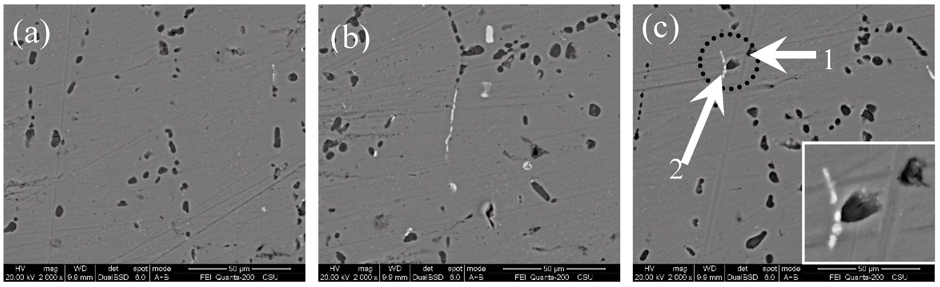
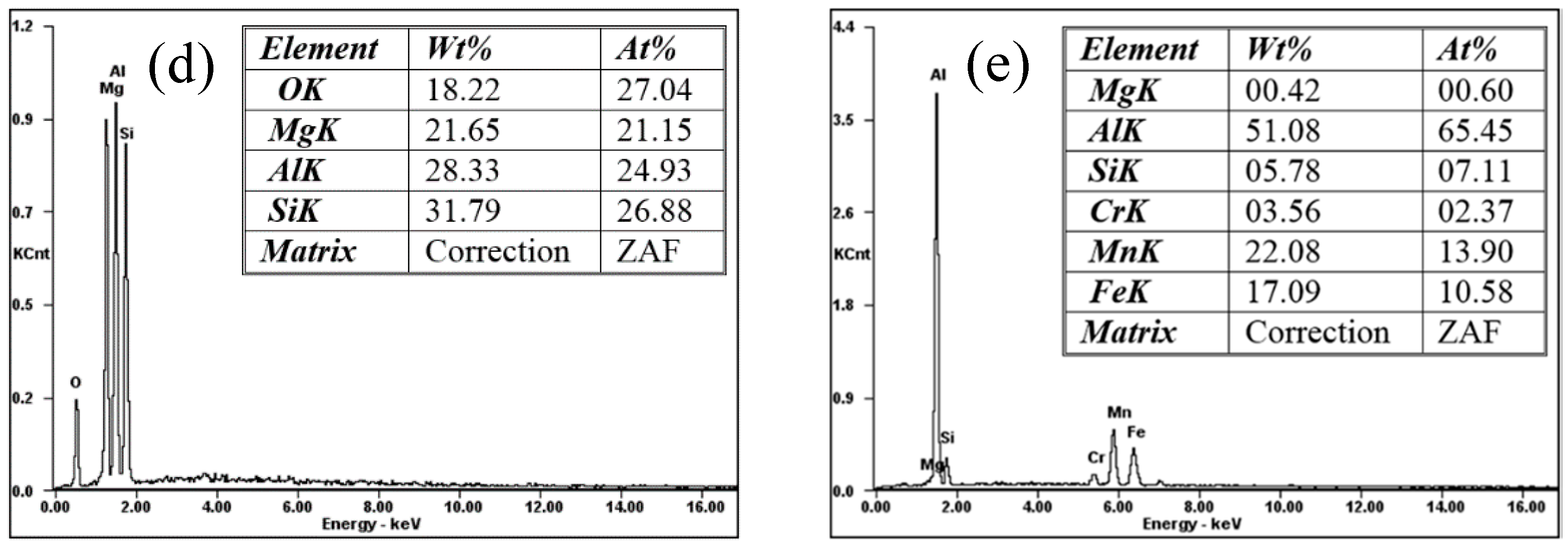
The backscattered electron images of the three alloys and corresponding energy dispersive X-ray spectroscopy (EDS) results are shown in Figure 1. Obviously, a high number of black areas identified as MgSi particles were identified by EDS. Since MgSi particles are hard and brittle, a portion of the particles fell off the aluminium matrix in the grinding process. In addition, elemental Si pits could have also fell. In addition to the MgSi precipitates, the emission scanning electron microscopy (SEM) images contained a small number of visible white particles, as shown in the white areas, which were mainly Al-Fe-Mn-Si intermetallics, including cubic (Al15(Fe,Mn)3Si2) and monoclinic (A15FeSi) phases. These intermetallics have high melting points and large sizes, and are formed in the process of casting and cannot be completely dissolved during the solution treatment.
2.2. Corrosion Tests
IGC tests were performed according to British standard 11,846 method B [34]. The standard involved the following steps: degreasing in ethanol, 5 min etching in 10 wt % NaOH, and 2 min desmutting in 30 wt % HNO3, followed by a 24 h immersion in an acidified sodium chloride solution (30 g NaCl and 10 mL HCl per litre). The surface and cross-sectional morphologies of the corroded samples were observed by an XJG-05 optical microscope (OM, Chincan, Dongguan, China) and JEOL JSM 6490 SEM instrument (JSM, Tokyo, Japan). For each condition, at least five valid parallel tests were performed to obtain statistical data of the IGC depth. Different immersion times were applied to clarify the evolution of the IGC process and the corrosion behaviour of MgSi particles during exposure of the Al-Mg-Si alloys in 3.5 wt % NaCl solution. Subsequently, the corroded surface appearance and corrosion depth on the cross-section were examined.
Potentiodynamic polarization measurements were performed using a conventional three-electrode electrochemical cell in 3.5 wt % NaCl solution at 25 ± 1 °C. A saturated calomel electrode (SCE) was used as the reference electrode, and a platinum sheet served as the auxiliary electrode. Samples with a size of 10 mm length × 10 mm width × 8 mm thickness were cut. Next, the polished face (L-T planes) was swept from an initial potential of −1.2 V to a final potential of 0.2 V at a scanning rate of 2 mV/s using an EG&G Model 273 Galvanostat/Potentiostat (GAMRY Reference 3000, Pennsylvania, PA, USA). The software plotted the polarization curve and calculated the corrosion current density (Icorr) and corrosion potential (Ecorr).
2.3. Characterization
The compositions and morphologies of the microstructures in the corroded samples were measured by an SEM instrument (JSM, Tokyo, Japan) equipped with EDS functionality. The detailed characteristics of the microstructures of the three investigated alloys were further observed by an FEI Tecnai G2 F20 TEM instrument (FEI, Hillsboro, OR, USA) operating at 200 kV. The samples for TEM characterization were prepared by mechanically grinding to 75 μm–95 μm, then punching into discs. The discs were perforated in an electrolyte consisting of 30% HNO3 and 70% methanol by Twin-Jet electropolishing. The electropolishing conditions were T = −25 °C and V = 22 V.
3. Results
3.1. Hardness Evolution During Ageing at 170 °C
The hardness evolutions for the three investigated Al-Mg-Si alloys with different Si contents treated by artificial ageing at 170 °C immediately after quenching are shown in Figure 2. The hardness curves of the three alloys displayed similar profiles, featuring a sharp rise in hardness within the first three hours, followed by a slow increase during the next three hours, and finally reaching maximum peak-aged hardness values of 123 HV, 127 HV, and 129 HV for alloys A, B, and C, respectively. The hardness remained at a relatively constant state for a long time, and with an increase in the ageing time, the hardness value gradually decreased. However, the required ageing time to obtain the maximum peak-aged hardness value was different for each alloy, and the ageing kinetics of the three alloys were different, as the increased Si content accelerated age-hardening. The age-hardening speed of alloy A with 1.21 wt % Si was the lowest amongst the three alloys, reaching a peak value of 123 HV after ageing for 4.5 h. By increasing the Si content to 1.73 wt %, the age-hardening rate and peak hardness value were both enhanced; after 4 h of ageing, alloy B reached a peak hardness of 127 HV. However, increasing the Si content to 2.52 wt % was not beneficial to further enhance the peak hardness value, as the hardness of the sample was not significantly greater than alloy B. In contrast, the hardness plateau became less and indistinct. From previous studies described in References [35,36], peak hardness was shown to be mainly due to the presence of high-density (Mg + Si) clusters and β′′ phase (Mg5Si6) precipitates, and an increased Si content increased the number of these strengthening phases. To further investigate strengthening phase microstructures and the difference among the peak-aged hardness values, the microstructures of the three alloys after peak-ageing treatment were characterized, as shown below.
3.2. Microstructure
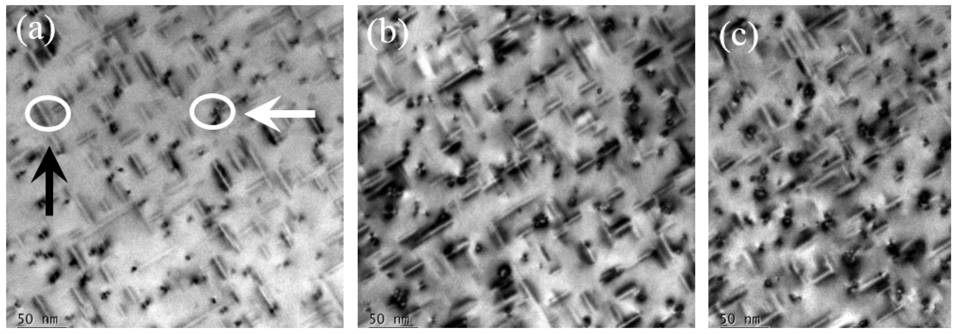
For the studied Al-Mg-Si alloys, the peak-aged state persisted for a long time. To acquire distinct microstructure views of the peak-aged states of the three alloys, all alloys were treated at 170 °C for 5 h (at the peak-aged state). Figure 3 shows the bright-field TEM images of the three alloys after being peak-aged at 170 °C for 5 h taken with the electron beam parallel to the [001]Al zone axis. A high-density of rod-shaped precipitates (marked with the black arrow) and cross-sections (marked with the white arrow) were dispersed in all the TEM images. As clearly observed, an increased Si content resulted in an increased number and density of these precipitates, and therefore the hardness and strength of the alloys accordingly improved, which is consistent with the previous literature [37,38].
To further analyse and confirm the structure of the rod-shaped precipitates in the three peak-aged alloys, a high-resolution TEM (HRTEM) image and corresponding fast Fourier filtering transform (FFT) pattern of the cross-section of a rod-shaped precipitate were obtained, as shown in Figure 4. The precipitate was polygonal and belonged to a monoclinic system with lattice parameters a = 1.51 nm, c = 0.67 nm, and β = 105.3° (Figure 4a). The aforementioned analysis results show that the precipitate was the β′′ phase through comparison with the published database [39] and the orientation relationships of (200)β′′ parallel to (301)Al. The main precipitate contributing to the peak hardness of the alloys was the β′′ precipitate elongated along the <001>Al axis with a rounded cross-section.
The composition and distribution of grain boundary particles in aluminium alloys play important roles in obtaining good corrosion resistance properties. The influence of the Si content in the Al-Mg-Si alloys on the grain boundary microstructure is shown in Figure 5. Alloy A (Figure 5a) did not exhibit obvious grain boundary precipitates, and the grain boundaries of alloys B (Figure 5b) and C (Figure 5c) were decorated with a mass of particles, but the PFZs of all the alloys were not obvious near the grain boundaries. These grain boundary precipitates observed in the TEM images consisted of two types of particles: (1) particles larger than 500 nm and (2) particles less than 100 nm, but only a few particles larger than 500 nm were found on the grain boundaries in these alloys. The large particles observed in all the alloys were Al-Fe-Si (Mn) dispersoids [40]. The numerous small rod-shaped particles on the grain boundaries in all three alloys were MgSi precipitates with sizes ranging from 0.1 μm–0.15 μm [40]. However, the structure of these MgSi precipitates is not studied in this paper; this will be further investigated and discussed in future research. With an increased Si content, the MgSi particle density on the boundaries increased, resulting in a more continuous distribution. In addition, solute-depleted zones of Mg and Si inevitably existed near the MgSi particles, although the PFZs could not be identified in these TEM images.
3.3. Corrosion Behaviour
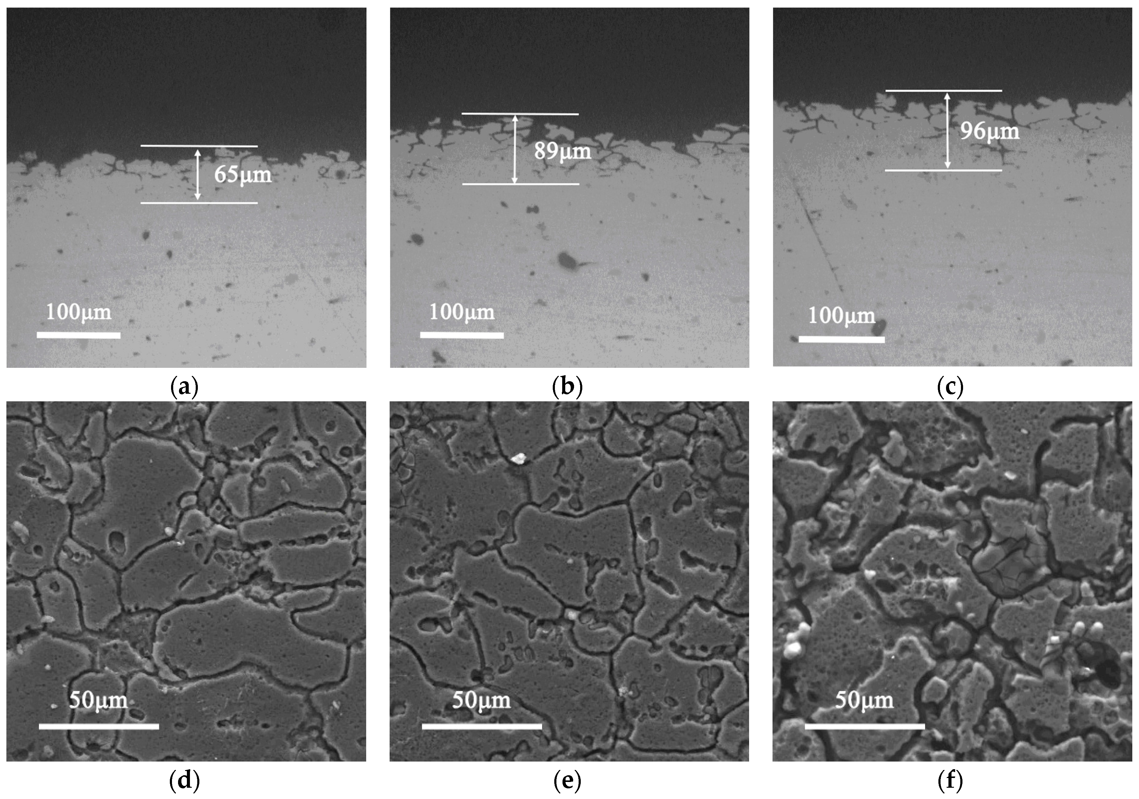
Figure 6 displays the corroded morphologies of the cross-sections and surfaces of the peak-aged (170 °C/5 h) Al-Mg-Si alloys after immersion in 3.5 wt % NaCl solution for 12 h, as per British standard 11,846 method B.
All the specimens displayed distinctly different degrees of IGC. The corrosion level was determined by the maximum IGC depth [34], and the values of the IGC depths and corrosion levels are presented in Table 3. Clearly, the typical IGC layers of all the samples were homogeneously distributed, but the degrees of corrosion varied. The IGC depth of alloy A with 1.21 wt % Si was 65 μm, and the entire sample presented superficial IGC (Figure 6a,d). With an increased Si content to 1.73 wt %, the IGC depth of alloy B increased, and some particles were stripped from the Al matrix (Figure 6b,e). Serious corrosion etched alloy C with a Si content of 2.52 wt %, displaying an IGC depth of 96 μm (Figure 6c,f). These different IGC depths demonstrated that alloy C presented the highest IGC susceptibility among the three alloys, as the increased Si content weakened the IGC corrosion resistance of the Al-Mg-Si alloys, which may be correlated to the density of MgSi precipitates on the grain boundaries. Alloys B and C displayed similar sizes, and maximum IGC depths (Table 3) were determined at the same IGC level.
3.4. Potentiodynamic Polarization Tests
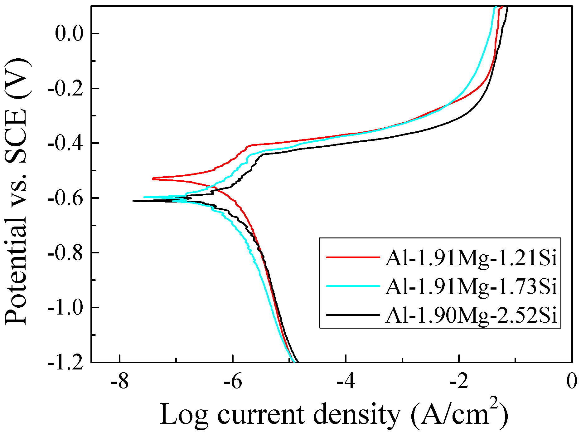
The potentiodynamic polarization curves of the three peak-aged samples are shown in Figure 7, and the polarization features (e.g., corrosion voltages, Ecorr, and corrosion current densities, Icorr) of the three studied alloys calculated from potentiodynamic polarization curves are presented in Table 4. The shapes of the polarization curves were largely unchanged with an increasing Si content. The anodic polarization behaviour was dictated by activated anodic dissolution with a sharp increase in current density at potentials higher than the pitting potential (Epit). As shown in Table 4, Icorr increased with an increasing Si content, which is consistent with the IGC test results.
3.5. Corrosion Process
The principle of IGC in age-hardened Al alloys is closely related to electrochemical corrosion, resulting from composition segregation and electrochemical microcouples continuously distributed along the grain boundaries. As previously stated, we concluded that the Si content of the Al-Mg-Si alloys was a predominant factor in the corrosion speed and level. Despite the different IGC levels of the three alloys, their IGC mechanisms are consistent. To uncover the common IGC mechanism of the Al-Mg-Si alloys with high Si contents, we selected alloy B as a representative sample with excellent integrated performance to elaborate and analyse the corrosion process. SEM images of a freshly polished alloy B surface aged at 170 °C for 5 h and subsequently exposed to a solution of 3.5 wt % NaCl for various times are shown in Figure 8. The corroded alloy morphologies with different exposure times showed the IGC process via the corrosion morphology and provided an overview of the corrosion evolution on the local surface and cross-section morphology of the Al-Mg-Si alloy. At the beginning of the corrosion process, corrosion occurred at and around the MgSi surface, and some corrosion trenching appeared around the particles. With an increasing corrosion time, the alloy presented obvious IGC, and the internal grains also displayed many corroded pits.
4. Discussion
To further clarify the IGC susceptibility and corrosion process of the high-Si-content alloy B at prolonged immersion time, two typical microstructural aspects must first be satisfied: (i) the grain boundary microstructures must contain a large number of discontinuously distributed MgSi precipitates and Al-Fe-Mn-Si intermetallics, and indistinguishable pure Si particles must exist; (ii) large differences must exist between the corrosion potentials of the grain boundary microstructures. Generally, the typical grain boundary microstructures in peak-aged Al-Mg-Si alloys mainly consist of MgSi precipitates, Al-Fe-Mn-Si intermetallics, pure Si, an Al matrix, and PFZ; however, the PFZ was not identified by TEM in this study. The concentration of Si and Mg atoms in the PFZ was lower than the aluminium matrix and precipitates, resulting in a lower corrosion potential at these solute-depleted zones than at the adjacent precipitates or Al matrix, which become the starting points of corrosion.
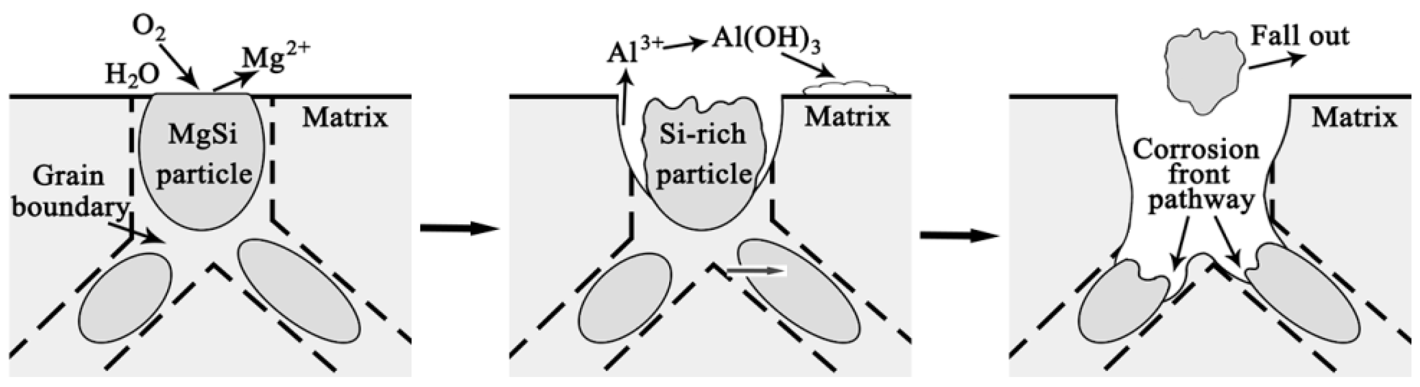
Figure 9 shows a schematic diagram of the IGC evolution of Al-Mg-Si alloys. When the peak-aged samples were immersed in the corrosive solution, the corrosion priority initiated from the grain boundary PFZ adjacent to the intermetallic or precipitate peripheries, and the grain boundary PFZ acted as an anode, resulting in anodic dissolution and the presence of a corrosion ring surrounding these Al-Fe-Mn-Si intermetallics and MgSi particles. Meanwhile, corrosion could also start at some intermetallics and precipitates due to preferential dissolution. After 4 h of immersion, these two main types of particles corroded, and considerable trenches surrounding the MgSi particles and Al-Fe-Mn-Si intermetallics were observed. During this corrosion process, the Si phase acted as a cathodic zone with strong polarization; however, the existence of pure Si in the grain boundary microstructures was not found, and corrosion dynamic conversion existed in the MgSi precipitate particles. During corrosion initiation, the MgSi precipitates underwent self-corrosion on their surface, resulting from the selective preferential dissolution of Mg in chloride-containing environments. As the corrosion time extended, the IGC continued into the corrosive MgSi phase, which led to Si gradually enriching the remnant MgSi particles, thus transforming polarity between the MgSi particles and solute-depleted zones and resulting in the MgSi particles becoming cathodic to the PFZ. In other words, the electrochemical driving force for the anodic dissolution of the solute-depleted zones increased, resulting in a larger dissolution velocity of the alloy due to larger differences in the corrosion potential between the de-alloyed MgSi particles and anode. This conversion was also found in some particles containing low corrosion potential elements. After 20 h of exposure to the corrosion solution, the corrosion trenching width around the particles was extensive—even forming a continuous corrosion channel, despite the fact that the MgSi precipitates were discontinuously distributed at the grain boundaries. In addition, some intergranular particle remnants were removed. After 40 h of immersion, many corroded small pits were found in the internal grains (submicro/nanometre range). These small pits may have been dissolved in the MgSi strengthening phase, and were not detectable before etching the micro-pits in the SEM images because of their infinitesimal size. As the corrosion time extended, corrosion constantly proceeded along the corrosion front pathway. Therefore, we uncovered a common corrosion evolution by analysing the abovementioned process, which we hope proves advantageous in improving alloy performances.
5. Conclusions
In this study, the hardness behaviours and IGC susceptibilities of the three alloys after ageing at 170 °C for different times were investigated by hardness tests, electrochemical experiments, SEM, and TEM. The precipitate microstructures and IGC evolutions of the peak-aged Al-Mg-Si alloys were uncovered, and the main conclusions can be summarized as follows:
- The hardness of the Al-Mg-Si alloys with peak-ageing treatments mainly originated from contribution from the β′′ phase. With an increased Si content, the age-hardening response improved, and the hardness value also increased by enhancing the quantity and density of the β′′ strengthening phase.
- The microstructures affecting the IGC performances the Al-Mg-Si alloys consisted of MgSi particles, Al-Fe-Mn-Si intermetallics, and the PFZ. The IGC susceptibility of the Al-Mg-Si alloys was mainly attributed to the high electrochemical potential difference between the MgSi particles and solute-depleted zones.
- Corrosion priority initiated from the grain boundary PFZ adjacent to the Al-Fe-Mn-Si intermetallics or from the MgSi precipitate peripheries forming a trench around the particles. Meanwhile, some intermetallics and precipitates displayed self-corrosion until dislodging after forming continuous corrosion channels. With an extended corrosion time, IGC constantly proceeded along the corrosion front pathway.
Acknowledgments
This study is supported by the Open Fund of Hunan Province Key Laboratory of Safety Design and Reliability Technology for Engineering Vehicle No. KF1604 and the National Defense Foundation of China No. 2011-006.
Author Contributions
Yaya Zheng and Binghui Luo conceived and designed the experiments; Yaya Zheng performed the experiments; Yaya Zheng and Zhenhai Bai analysed the data; Juan Wang and Yuan Yin contributed reagents/materials/analysis tools; Yaya Zheng wrote the paper.
Conflicts of Interest
The authors declare no conflict of interest.
References
- Hua, D.R.; Yang, W.S.; Yu, Z.H.; Wu, P.; Hussain, M.; Jiang, L.T.; Wu, G.H. Aging behavior of 6061Al matrix composite reinforced with high content SiC nanowires. J. Alloys Compd. 2015, 649, 1037–1042. [Google Scholar]
- Lin, C.W.; Hung, F.Y.; Lui, T.S.; Chen, L.H. Microstructure Evolution and High-Temperature Compressibility of Modified Two-Step Strain-Induced Melt Activation-Processed Al-Mg-Si Aluminum Alloy. Metals 2016, 6, 113. [Google Scholar] [CrossRef]
- Kaseem, M.; Choi, K.; Ko, Y.G. A highly compact coating responsible for enhancing corrosion properties of Al-Mg-Si alloy. Mater. Lett. 2017, 196, 316–319. [Google Scholar] [CrossRef]
- Li, J.R.; Kai, W.; Jiang, Q.T.; Sun, H.Y.; Li, Y.T.; Hou, B.R.; Li, W.Z.; Liu, M. Corrosion and Discharge Behaviors of Mg-Al-Zn and Mg-Al-Zn-In Alloys as Anode Materials. Metals 2016, 6, 65. [Google Scholar] [CrossRef]
- Yin, D.; Xiao, Q.; Chen, Y.Q.; Liu, H.Q.; Yi, D.Q.; Wang, B.; Pan, S.P. Effect of natural ageing and pre-straining on the hardening behavior and microstructural response during artificial ageing of an Al-Mg-Si-Cu alloy. Mater. Des. 2016, 95, 329–339. [Google Scholar] [CrossRef]
- Farlkoosh, A.R.; Pekguleryuz, M. Enhanced mechanical properties of an Al-Si-Cu-Mg alloy at 300 °C: Effects of Mg and the Q-precipitate phase. Mater. Sci. Eng. A 2015, 621, 277–286. [Google Scholar] [CrossRef]
- Yin, M.J.; Chen, J.H.; Wang, S.B.; Liu, Z.R.; Cha, L.M.; Duan, S.Y.; Wu, C.L. Anisotropic and temperature-dependent growth mechanism of S-phase precipitates in Al-Cu-Mg alloy in relation with GPB zones. Trans. Nonferrous Met. Soc. China 2016, 26, 1–11. [Google Scholar] [CrossRef]
- Xu, X.X.; Yang, Z.; Ye, Y.L.; Wang, G.X.; He, X.L. Effects of various Mg/Si ratios on microstructure and performance property of Al-Mg-Si alloy cables. Mater. Charact. 2016, 119, 114–119. [Google Scholar] [CrossRef]
- EcKermannae, F.; Sutera, T.; Uggowitzerv, P.J.; Afseth, A.; Schmutz, P. The influence of MgSi particle reactivity and dissolution processes on corrosion in Al-Mg-Si alloys. Electrochim. Acta 2008, 54, 844–855. [Google Scholar] [CrossRef]
- Chrominski, W.; Lewandowska, M. Precipitation phenomena in ultrafine grained Al-Mg-Si alloy with heterogeneous microstructure. Acta Mater. 2016, 703, 547–557. [Google Scholar] [CrossRef]
- Nassef, A.; El-Garaihy, W.H.; El-Hadek, M. Mechanical and Corrosion Behavior of Al-Zn-Cr Family Alloys. Metals 2017, 7, 171. [Google Scholar] [CrossRef]
- Hai, L.; Mao, Q.Z.; Wang, Z.X.; Miao, F.F.; Fang, B.J.; Song, R.G.; Zheng, Z.Q. Enhancing mechanical properties of Al-Mg-Si-Cu sheets by solution treatment substituting for recrystallization annealing before the final cold-rolling. Mater. Sci. Eng. A 2014, 620, 204–212. [Google Scholar]
- Ding, L.P.; Jia, Z.H.; Zhang, Z.Q.; Sanders, R.E.; Liu, Q.; Yang, G. The natural aging and precipitation hardening behavior of Al-Mg-Si-Cu alloys with different Mg/Si ratios and Cu additions. Mater. Sci. Eng. A 2015, 627, 119–126. [Google Scholar] [CrossRef]
- Cao, C.; Zhang, D.; Wang, X.; Ma, Q.B.; Zhuang, L.Z.; Zhang, J.S. Effects of Cu addition on the precipitation hardening response and intergranular corrosion of Al-5.2Mg-2.0Zn (wt %) alloy. Mater. Charact. 2016, 122, 177–182. [Google Scholar] [CrossRef]
- Jiang, J.T.; Xiao, W.Q.; Yang, L.; Shao, W.Z.; Yuan, S.J.; Zhen, L. Ageing behavior and stress corrosion cracking resistance of a non-isothermally aged Al-Zn-Mg-Cu alloy. Mater. Sci. Eng. A 2014, 605, 167–175. [Google Scholar] [CrossRef]
- Song, F.X.; Zhang, X.M.; Liu, S.D.; Tan, Q.; Li, D.F. The effect of quench rate and overaging temper on the corrosion behavior of AA7050. Corros. Sci. 2014, 78, 276–286. [Google Scholar] [CrossRef]
- Zhang, X.X.; Zhou, X.R.; Hashimoto, T.; Liu, B. Localized corrosion in AA2024-T351 aluminum alloy: Transition from intergranular corrosion to crystallographic pitting. Mater. Charact. 2017, 130, 230–236. [Google Scholar] [CrossRef]
- Bonfils-Lahovary, M.L.; Laffont, L.; Blanc, C. Characterization of intergranular corrosion defects in a 2024 T351 aluminum alloy. Corros. Sci. 2017, 119, 60–67. [Google Scholar] [CrossRef]
- Bonzom, R.; Oltra, R. Droplet cell investigation of intergranular corrosion on AA2024. Electrochem. Commun. 2017, 81, 84–87. [Google Scholar] [CrossRef]
- Tang, Y.; Zhang, L.J.; Du, Y. Diffusivities in liquid and fcc Al-Mg-Si alloys and their application to the simulation of solidification and dissolution processes. Calphad 2015, 49, 58–66. [Google Scholar] [CrossRef]
- Ferguson, J.B.; Lopez, H.E.; Cho, K.; Kim, C.S.; Farlkoosh, A.R.; Pekguleryuz, M. Temperature Effects on the Tensile Properties of Precipitation-Hardened AI-Mg-Cu-Si Alloys. Metals 2016, 6, 43. [Google Scholar] [CrossRef]
- Kaseem, M.; Min, J.H.; Ko, Y.G. Corrosion behavior of Al-1 wt % Mg-0.85 wt % Si alloy coated by micro-arc-oxidation using TiO2 and Na2MoO4 additives: Role of current density. J. Alloys Compd. 2017, 723, 448–455. [Google Scholar] [CrossRef]
- Svenningsen, G.; Larsen, M.H.; Nordlien, J.H. Nisancioglu, K. Effect of high temperature heat treatment on intergranular corrosion of AlMgSi(Cu) model alloy. Corros. Sci. 2006, 48, 258–272. [Google Scholar] [CrossRef]
- Mol, J.M.C.; Langkruis, J.; Wit, J.H.W.; Zwaag, S. An integrated study on the effect of pre-and post-extrusion heat treatments and surface treatment on the filiform corrosion properties of an aluminum extrusion alloy. Corros. Sci. 2005, 47, 2711–2730. [Google Scholar] [CrossRef]
- Li, J.F.; Maier, B.; Frankel, G.S. Corrosion of an Al-Mg-Si alloy under MgCl2 solution droplets. Corros. Sci. 2011, 53, 2142–2151. [Google Scholar] [CrossRef]
- Mizuno, K.; Nylund, A.; Olefjord, I. Surface reactions during pickling of an aluminum-magnesium-silicon alloy in phosphoric acid. Corros. Sci. 2001, 43, 381–396. [Google Scholar] [CrossRef]
- Li, C.; Sun, J.Y.; Li, Z.D.; Gao, Z.M.; Liu, Y.C.; Yu, L.M.; Li, H.J. Microstructure and corrosion behavior of Al-10%Mg2Si cast alloy after heat treatment. Mater. Charact. 2016, 122, 142–147. [Google Scholar] [CrossRef]
- Zeng, L.F.; Wei, Z.L.; Li, J.F.; Li, C.X.; Xing, T.; Zhao, Z.; Zheng, Z.Q. Corrosion mechanism associated with Mg2Si and Si particles in Al-Mg-Si alloys. Trans. Nonferrous Met. Soc. China 2011, 21, 2559–2567. [Google Scholar] [CrossRef]
- Li, C.X.; Li, J.F.; Birbilis, N.; Jia, Z.Q.; Zheng, Z.Q. Synergetic effect of Mg2Si and Si particles on intergranular corrosion of Al-Mg-Si alloys through multi-electrode coupling system. J. Chin. Soc. Corros. Prot. 2010, 30, 107–113. [Google Scholar]
- Blanc, C.; Roques, Y.; Mankowski, G. Application of phase shifting interferometric microscopy to studies of the behavior of coarse intermetallic particles in 6056 aluminum alloys. Corros. Sci. 1998, 40, 1019–1035. [Google Scholar] [CrossRef]
- Ahlatci, H. Production and corrosion behaviors of the Al-12Si-XMg alloys containing in situ Mg2Si particles. J. Alloys Compd. 2010, 503, 122–126. [Google Scholar] [CrossRef]
- Bhattamishra, A.K.; Lal, K. Microstructural studies on the effect of Si and Cr on the intergranular corrosion in Al-Mg-Si alloys. Mater. Des. 1997, 27, 25–28. [Google Scholar] [CrossRef]
- Liang, W.J.; Rometsch, P.A.; Cao, L.F.; Birbilis, N. General aspects related to the corrosion of 6xxx series aluminum alloys: Exploring the influence of Mg/Si ratio and Cu. Corros. Sci. 2013, 76, 119–128. [Google Scholar] [CrossRef]
- Wang, Z.X.; Li, H.; Miao, F.F.; Sun, W.Z.; Fang, B.F.; Song, R.G.; Zheng, Z.Q. Improving the intergranular corrosion resistance of Al-Mg-Si-Cu alloys without strength loss by a two-step aging treatment. Mater. Sci. Eng. A 2014, 590, 267–273. [Google Scholar] [CrossRef]
- Masuda, T.; Takaki, Y.; Sakurai, T.; Hirosawa, S. Combined effect of pre-straining and pre-aging on bake-hardening behavior of an A1-0.6 massy Mg-1.0 massy Si alloy. Mater. Trans. 2010, 51, 325–332. [Google Scholar] [CrossRef]
- Yassar, R.S.; Cai, M.; Field, D.P.; Chen, X.; Asay, J. The effect of shock-loading aging behavior of an Al-Mg-Si alloy. J. Mater. Sci. 2006, 41, 1711–1720. [Google Scholar] [CrossRef]
- Buchanan, K.; Colas, K.; Ribis, J.; Lopez, A.; Gamier, J. Analysis of the metastable precipitates in peak-hardness aged Al-Mg-Si(-Cu) alloys with differing Si contents. Acta Mater. 2017, 132, 209–221. [Google Scholar] [CrossRef]
- Ding, X.P.; Cui, H.; Zhang, J.X.; Li, H.X.; Guo, M.X.; Lin, Z.; Zhuang, L.Z.; Zhang, J.S. The effect of Zn on the age hardening response in an Al-Mg-Si alloy. Mater. Charact. 2015, 65, 1229–1235. [Google Scholar] [CrossRef]
- Chen, J.H.; Costan, E.; Van-huis, M.A.; Xu, Q.; Zandbergen, H.W. Atomic Pillar-Based Nanoprecipitates Strengthen AlMgSi Alloys. Science 2006, 312, 416–420. [Google Scholar] [CrossRef] [PubMed]
- Zou, Y.; Qing, L.; Jia, Z.H.; Xing, Y.; Ding, L.P.; Wang, X.L. The intergranular corrosion behavior of 6000-series alloys with different Mg/Si and Cu content. Appl. Surf. Sci. 2017, 405, 489–496. [Google Scholar] [CrossRef]
Figure 1.
SEM images of the samples: (a) alloy A, (b) alloy B, and (c) alloy C. (d,e) Corresponding energy dispersive X-ray spectroscopy (EDS) results of particles from mark 1 and 2, respectively. (ZAF: Correction for Quantitative Electron-probe Microanalysis of Microparticles).
Figure 1.
SEM images of the samples: (a) alloy A, (b) alloy B, and (c) alloy C. (d,e) Corresponding energy dispersive X-ray spectroscopy (EDS) results of particles from mark 1 and 2, respectively. (ZAF: Correction for Quantitative Electron-probe Microanalysis of Microparticles).


Figure 2.
Vickers hardness evolution of the three alloys with ageing time at 170 °C immediately after quenching (error limit ±2%).
Figure 2.
Vickers hardness evolution of the three alloys with ageing time at 170 °C immediately after quenching (error limit ±2%).
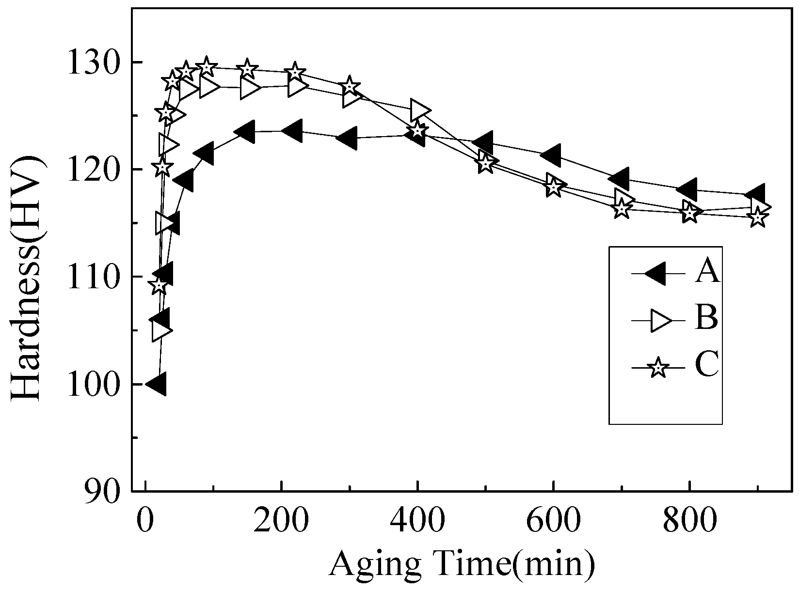
Figure 3.
TEM micrographs of the three alloys at peak-ageing conditions: (a) alloy A, (b) alloy B, and (c) alloy C.
Figure 3.
TEM micrographs of the three alloys at peak-ageing conditions: (a) alloy A, (b) alloy B, and (c) alloy C.

Figure 4.
High-resolution TEM (HRTEM) images of a representative β′′ precipitate imaged parallel to the <010>Al axis of the precipitates in the peak-aged (170 °C/5 h) Al-Mg-Si alloy: (a) HRTEM image and (b) the corresponding fast Fourier filtering transform (FFT) pattern.
Figure 4.
High-resolution TEM (HRTEM) images of a representative β′′ precipitate imaged parallel to the <010>Al axis of the precipitates in the peak-aged (170 °C/5 h) Al-Mg-Si alloy: (a) HRTEM image and (b) the corresponding fast Fourier filtering transform (FFT) pattern.
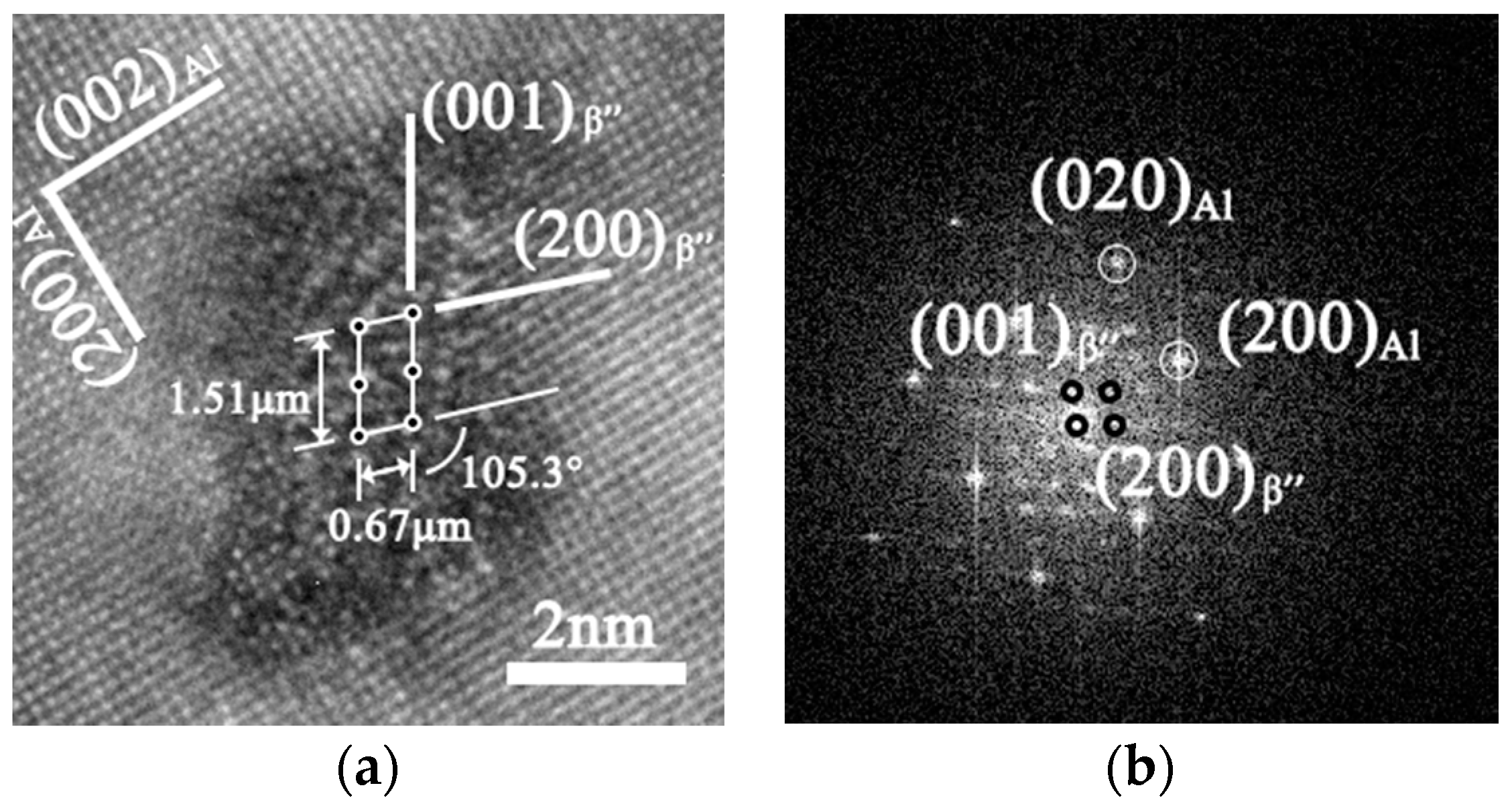
Figure 5.
TEM images showing the distributions of grain boundary particles in (a) alloy A, (b) alloy B, and (c) alloy C.
Figure 5.
TEM images showing the distributions of grain boundary particles in (a) alloy A, (b) alloy B, and (c) alloy C.
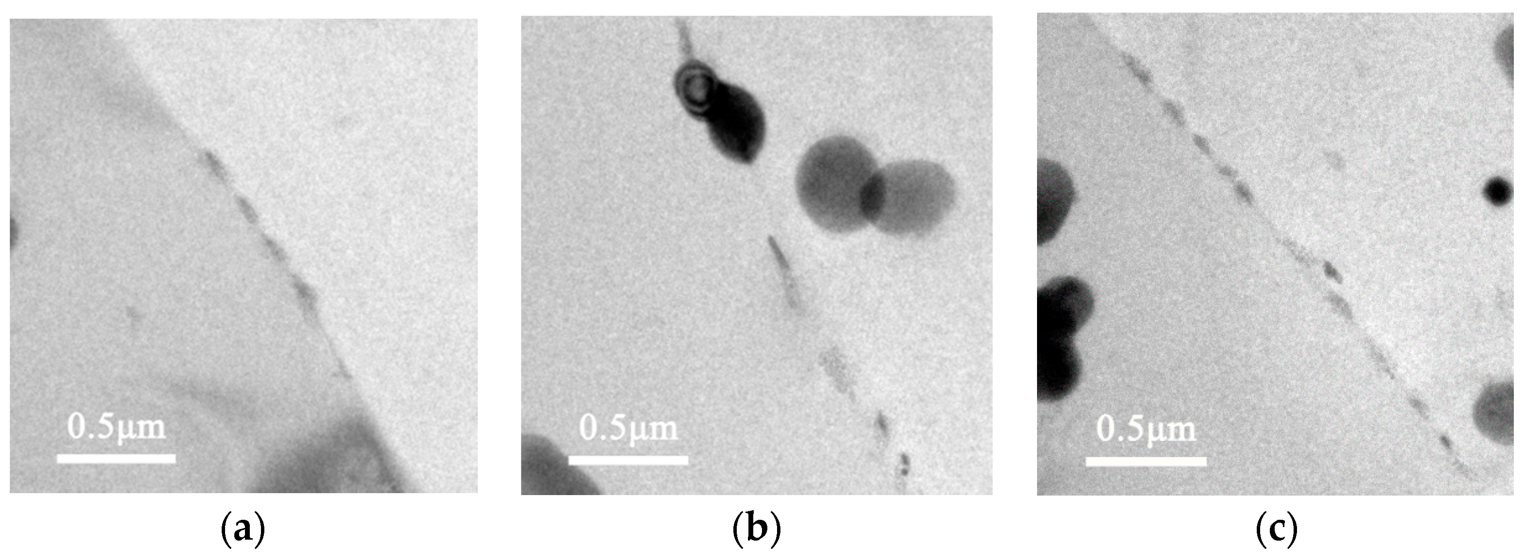
Figure 6.
Typical IGC cross-sections and corresponding surface morphologies of the corroded Al-Mg-Si alloys with different Si contents: (a,d) alloy A, (b,e) alloy B, and (c,f) alloy C.
Figure 6.
Typical IGC cross-sections and corresponding surface morphologies of the corroded Al-Mg-Si alloys with different Si contents: (a,d) alloy A, (b,e) alloy B, and (c,f) alloy C.

Figure 7.
Polarization curves of the peak-aged Al-Mg-Si alloys with different Si contents tested in IGC solution. SCE: saturated calomel electrode.
Figure 7.
Polarization curves of the peak-aged Al-Mg-Si alloys with different Si contents tested in IGC solution. SCE: saturated calomel electrode.

Figure 8.
Corrosion evolution of the Al-Mg-Si alloy after immersion in 3.5 wt % NaCl solution.
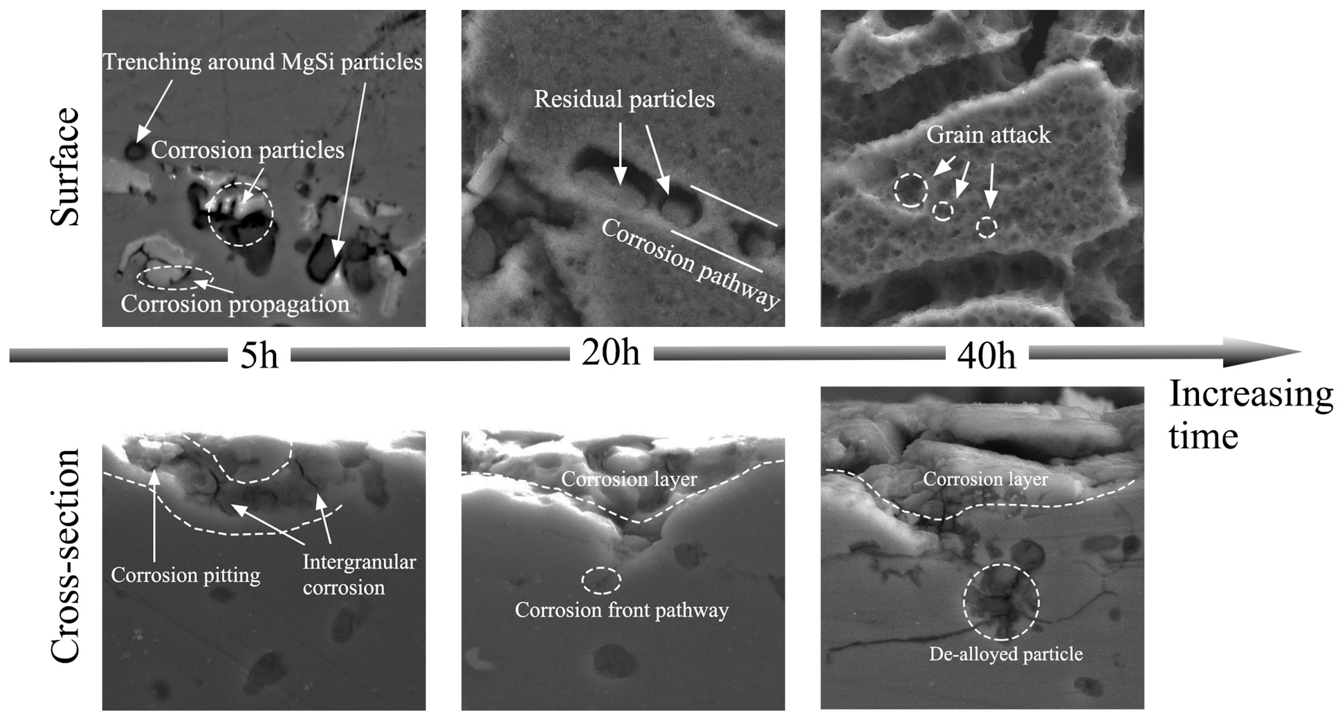
Figure 9.
Schematic diagram of the corrosion evolution of a cross-section of the Al-Mg-Si alloy.

Table 1.
Summary of the corrosion behaviours of Al-Mg-Si alloys.
| Alloys (Composition in wt %) | Heat Treatment Conditions | Corrosion Form | Corrosion Mechanism |
|---|---|---|---|
| Al-6.34Mg-3.66Si | 520 °C/6 h (ST) + aged at 200 °C/6 h | IGC | Propagation of corrosion pits in the corrosive media occurs along the interface between the MgSi particles and α-Al [27]. |
| Al-0.63Mg-0.28Si and Al-0.63Mg-0.88Si | ST + aged at 175 °C/1 h | The ratio of Mg to Si less than 1.73 resulted in IGC | Corrosion initiates on the MgSi surface and PFZ. Corrosion develops along the grain boundary PFZ at the adjacent MgSi precipitates [28]. |
| Al-1.31Si-0.4Mg and Al-0.6Si-0.52Mg-0.18Cu | 540 °C/30 min (ST) + aged at 185 °C | Aged sample is susceptible to IGC | IGC caused by micro-galvanic coupling between the cathodic Cu-containing precipitates and solute-depleted active zone [29]. |
| Al-0.86Mg-0.92Si | 550 °C/ST + aged at 175 °C/8 h | - | Very strong dissolution of the Al-Mg- and Si-containing particles along the grain boundaries [30]. |
| Al-12Si-0Mg and Al-12Si-5Mg and Al-12Si-10Mg and Al-12Si-20Mg | Casting | - | Corrosion primarily initiates from the Al matrix adjacent to the primary Mg2Si particles [31]. |
| Al-0.4Mg-1.0Si | 550 °C/1 h + aged at 175 °C/16 h | IGC | Precipitation of MgSi at the grain boundary favours intergranular corrosion attack [32]. |
| Al-0.6Mg-0.5Si | T6 | - | MgSi particles were anodically precipitated compared to the Al matrix in acidic and neutral pH [33]. |
IGC: intergranular corrosion; PFZ: precipitate-free zone; ST: solution treatment.
Table 2.
Chemical compositions of the examined alloys (wt %).
| Sample | Chemical Compositions | ||||||||
|---|---|---|---|---|---|---|---|---|---|
| Mg | Si | Fe | Cr | Mn | Zr | Ti | Ag | Al | |
| A | 1.91 | 1.21 | ≤0.1 | 0.13 | 0.29 | 0.098 | 0.1 | 0.1 | Bal. |
| B | 1.91 | 1.73 | ≤0.1 | 0.12 | 0.29 | 0.11 | 0.1 | 0.1 | Bal. |
| C | 1.90 | 2.52 | ≤0.1 | 0.14 | 0.28 | 0.10 | 0.1 | 0.1 | Bal. |
Table 3.
Maximum IGC depths for the Al-Mg-Si alloys at peak-aged conditions.
| Alloy | Maximum Corrosion Depth (μm) | IGC Level |
|---|---|---|
| A | 65 | 3 |
| B | 89 | 3 |
| C | 96 | 4 |
Table 4.
Ecorr and Icorr values of the three alloys from the polarization curves determined by the Tafel extrapolation method.
Table 4.
Ecorr and Icorr values of the three alloys from the polarization curves determined by the Tafel extrapolation method.
| Alloy | Corrosion Potential, Ecorr (mV) | Corrosion Current Density, Icorr (μA/cm2) | Pitting Potential, Epit (V) |
|---|---|---|---|
| A | −532 ± 6 | 0.47 ± 0.02 | –0.408 |
| B | −612 ± 4 | 0.55 ± 0.06 | –0.440 |
| C | −606 ± 6 | 0.57 ± 0.04 | –0.453 |
© 2017 by the authors. Licensee MDPI, Basel, Switzerland. This article is an open access article distributed under the terms and conditions of the Creative Commons Attribution (CC BY) license (http://creativecommons.org/licenses/by/4.0/).
Share and Cite
MDPI and ACS Style
Zheng, Y.; Luo, B.; Bai, Z.; Wang, J.; Yin, Y. Study of the Precipitation Hardening Behaviour and Intergranular Corrosion of Al-Mg-Si Alloys with Differing Si Contents. Metals 2017, 7, 387. https://doi.org/10.3390/met7100387
AMA Style
Zheng Y, Luo B, Bai Z, Wang J, Yin Y. Study of the Precipitation Hardening Behaviour and Intergranular Corrosion of Al-Mg-Si Alloys with Differing Si Contents. Metals. 2017; 7(10):387. https://doi.org/10.3390/met7100387
Chicago/Turabian StyleZheng, Yaya, Binghui Luo, Zhenhai Bai, Juan Wang, and Yuan Yin. 2017. "Study of the Precipitation Hardening Behaviour and Intergranular Corrosion of Al-Mg-Si Alloys with Differing Si Contents" Metals 7, no. 10: 387. https://doi.org/10.3390/met7100387
Note that from the first issue of 2016, this journal uses article numbers instead of page numbers. See further details here.