Numerical Simulation of Ti/Al Bimetal Composite Fabricated by Explosive Welding

1
School of Material Science and Engineering, Taiyuan University of Science and Technology, No. 66 Waliu Road, Taiyuan 030024, China
2
School of Mechanical Engineering, Taiyuan University of Science and Technology, No. 66 Waliu Road, Taiyuan 030024, China
3
Department of Chemical and Materials Engineering, University of Alberta, Edmonton, AB T6G 2R3, Canada
*
Author to whom correspondence should be addressed.
Metals 2017, 7(10), 407; https://doi.org/10.3390/met7100407
Submission received: 17 August 2017
/
Revised: 20 September 2017
/
Accepted: 25 September 2017
/
Published: 1 October 2017
Abstract
:In this paper, a 2D numerical model that is more physically realistic was established to simulate the complete process of Ti/Al explosive welding. Basing on the ANSYS/AUTODYN software package, the smoothed particle hydrodynamics (SPH) and arbitrary Lagrangian-Eulerian (ALE) were used for running this simulation. The numerical model can capture the typical physics in the explosive welding process, including the expansion of explosives, flyer plate bending, the impact of metal plates, jetting, and the wavy interface. The variable physical parameters during the explosive welding process were discussed. Most parts of the jet originated from the aluminum plate. According to the model, the jet velocity reached 7402 m/s. The pressure at the detonation point was too small to make the two plates to bond. The pressure could reach an order of magnitude of 107 kPa when the detonation energy tended to be stable and was far more than the yield strength of both materials, which resulted in an obvious narrow region of plastic strain emerging close to the collision zone. The signs of shear stresses between the two plates were the opposite. The interface morphology changed from straight to wave along the propagation of the detonation wave in the simulation, which was consistent with the experimental results.
1. Introduction
Laminated metal composites have broad development prospects and have been applied in many fields, such as aerospace, equipment manufacturing, and chemical industries [1,2,3]. Explosive welding (EXW) is one of the effective technologies to manufacture laminated metal composites with controllable thermal conductivity, ideal mechanical properties, better erosion resistance, and obvious economic benefits. Over 260 various similar and dissimilar materials can be fabricated by using explosive welding techniques [1,3,4].
Explosively driven impact welding belongs to the field of multidisciplinary research, which relates to complex chemical reactions (e.g., explosive explosion), physical processes (e.g., hypervelocity impact), and metallurgical processes (e.g., welding of metals) [5]. Due to the fact that these phenomena mentioned above complete in a very short duration under high temperature and high pressure, the transient forming process is difficult to be observed and measured in an experiment, and the time history seems difficult to understand as well.
With the development of computer software and hardware technologies, the finite element method (FEM) has been applied to study the explosive/impact welding in recent works. Nassiri and Kinsey [6] studied the process of the high-velocity impact welding by using SPH (smoothed particle hydrodynamics) and ALE (arbitrary Lagrangian-Eulerian) methods, respectively. Simulation results of both of these methods, such as interfacial waves, the shear stress, and velocity in the vicinity of the collision point were consistent. However, the phenomenon of jetting was only reproduced in the simulation by using the SPH method. Wang et al. [7] applied the SPH method to study the mechanisms and the physical phenomenon of the explosion welding of titanium and its alloys. In their simulations, the changing physical processes involving shear stress and effective plastic strain of materials were clearly shown. Nassiri et al. [8] predicted the weldability window of the high-velocity impact welding by using ALE finite element method. An experiment was conducted to validate the FEA (finite element analysis) model and the weldability window. The results of the experiments and numerical simulations were completely consistent. Aizawa et al. [9] investigated the chemical composition, the intermediate layers at explosive-welded Al/Fe joint interfaces by experimental and numerical analyses. The temperature distribution near the interface shown by the SPH simulation explained the formation mechanism of two types of intermetallic compound. Abe [10] used a two-dimensional finite difference scheme to research the mechanism of the wavy interface generation in explosive welding. The computational results agreed very well with the experimental results. Yuan et al. [11] studied the process of 6061 Al/AZ31B explosive welding using SPH. The wavy interface and the phenomenon of jetting were reproduced, but the detailed mechanism of the interface wavy structure was not illustrated. Grignon et al. [12] studied the conditions for a straight, smooth weld formation in the explosive welding of 6061 T0 and 6061 T0. In their study, the numerical simulation and the analytical calculations were used to confirm the experimental results and explain the difficulties met with obtaining a continuous straight interface. The numerical simulation results demonstrated that the change in the collision angle was directly responsible for the change in the interface morphology from wavy to smooth. Mousavi and Al-Hassani [5] used an Euler processor to model the explosive/impact welding process, but the historical process data of explosive welding was difficult to be understood using Euler computation. Carrino et al. [13] studied the effect of workpiece thickness in superplastic forming/diffusion bonding of a titanium alloy by using finite element analysis.
However, the numerical models in aforementioned research simplified the actual explosive welding process, and ignored the explosion of explosives and the acceleration of the flyer plate [6,7,8,11,14]. Basing on the Gurney formula or Richter formula, they regarded the explosive welding process as high-velocity impact welding (HVIW). Specifically, the simulation was performed by imposing a constant impact velocity for the flier plate (V) and giving an initial angle (β) between the flier and base plates as the initial conditions, as shown in Figure 1. In order to reproduce the actual physical process of explosive welding, the explosion of explosives and the acceleration of the flyer plate should be also considered.
Ti/Al bimetal composites have been widely used in the industry [1,3,15,16,17]. There are many reports concerning the EXW of Ti and Al. Most previous experimental studies focused on the microstructure and mechanical characteristics of Ti/Al layered materials [3,16,17]. However, the forming process of explosive welding of Ti/Al is still not clear. Few studied the explosive welding process of Ti/Al layered materials by simulation.
The present work is motived by the research involving numerical simulation of a Ti/Al bimetal composite fabricated by explosive welding. The numerical model that is closer to reality is applied to study the explosive welding of the Ti/Al composite plate. The characteristic phenomena in the Ti/Al explosive welding process are reproduced and some physical parameters, such as collision velocity, pressure, effective plastic strain, and shear stress, are also discussed. The interfacial morphology of the Ti/Al composite in the numerical simulations was compared with an experimental test. The numerical simulations provide an efficient way to make us study the inherent physics of explosive welding. This paper may provide a new contribution in the field of Ti/Al laminated composite manufacturing.
2. Explosive Welding Model
AUTODYN is a commercial software (AUTODYN 6.1, Century Dynamics Incorporated, Concord, CA, USA) for analyzing high-velocity impacts, explosions, and shock waves, etc. [7,9,11]. It was originally developed by Century Dynamics (Concord, CA, USA) and later embedded as a software module within the ANSYS workbench platform. In the present article, a 2D-Planar calculation model in AUTODYN is used for the explosive welding simulation.
2.1. Geometric Model of Explosive Welding
In the current model, the TA1 plate is the flyer plate, and Al 1060 is the base plate, and anvil stands for the foundation. A geometric model for the Ti/Al explosive welding simulation is shown in Figure 2. It is comprised of four materials, i.e., Al, Ti, anvil (steel), and ANFO (ammonium-nitrate/fuel-oil). The geometry sizes are listed in Table 1. The detonator is installed on the surface edge of the explosive layer. The default units in AUTODYN are used in the simulation, i.e., the length unit is mm, the mass unit is mg, and the time unit is ms. Some equidistant gauge points with 4 mm between adjacent ones are selected at the top surface of Al plate and the lower surface of Ti plate along the detonation direction, respectively. The 12 numbered squares in the Figure 2 represent the gauge points.
2.2. Equation of State (EOS) and Constitutive Model
The Jones-Wilkins-Lee (JWL) state equation was used for the ANFO mixture [18]. The JWL expresses pressure as a function of volumetric strain and specific internal energy. It can be calculated as follows (Equation (1)) [9,19]:
where P represents pressure, V is the relative volume, E0 is the initial specific internal energy, and A, B, R1, R2, as well as ω are constants of explosive, as shown in Table 2.
In the present simulation, the flyer plate and the parent plate in explosive welding process were subjected to large strains and high strain rates. Here, a Mie-Gruneisen EOS were applied as the equation of state for the plates and anvil. The Mie-Gruneisen EOS based on the shock Hugoniot of an impact event and was widely used in materials with large deformation. This EOS describes the essential relationship between particle velocity and shock velocity, which are of the following forms (Equations (2)–(6)) [7,11]:
where
and:
where is the Gruneisen coefficient, ρ is the current density, ρ0 is the initial density, and c0 is the bulk speed of sound [21]. The default AUTODYN shock EOS material constants were used throughout the simulations here.
The constitutive model should be used to represent the mechanical behavior of metals. Since the Johnson-Cook model (Equations (7) and (8)) [22] can effectively describe the large deformation behavior of materials at high strain rates it was applied to the flyer plate, parent plate, and anvil for their mechanical behavior analysis:
where σ is the flow stress, εeff is the effective plastic strain, is the normalized effective plastic strain rate, Rτ is shear stress of materials, Y0 is yield stress of materials, Troom is room temperature, Tmelt represents the melting point of materials and A, B, C, n, and m are material parameters. The influence of temperature on the flow stress of the material in Johnson-Cook model were elaborated in [23,24]. The material constants were extracted from the AUTODYN material library [20], as listed in Table 3.
2.3. Algorithm Selection
Algorithms are indispensable for implementing the numerical simulation. A variety of algorithms were proposed in the literature. However, each algorithm has its advantages and weaknesses.
The Lagrangian finite element method is commonly used to model solids. A traditional pure Lagrangian method in which the mesh is fixed to the workpiece geometry can induce excessive element distortion when large deformations occurs near the contact zone [25], leading to the breakdown of the computation.
In the Eulerian algorithm, nodes are fixed spatially, and material flows through the elements [8]. The Eulerian algorithm is a kind of feasible techniques to solve large strains and high strain rates. Nevertheless, it has some disadvantages as well. For instance, the space and computational complexities are much higher than the traditional Lagrangian analysis. In addition, tracking the interface is difficult in the Eulerian algorithm [8,26].
Smoothed particle hydrodynamics (SPH) is a mesh free algorithm in which a set of particles is exploited to represent the materials. Due to its good performance in avoiding element distortion, it is beneficial for dealing with some large deformation problems [27]. SPH has been used to research the explosive/impact welding in recent reports [6,7,11,19].
The arbitrary Lagrangian-Eulerian (ALE) technique is a good fusion of conventional Lagrangian and Eulerian methods, as it exhibits good properties in large deformation simulation of materials in which a high quality mesh is adaptively adjusted and maintained. Nevertheless, the ALE method is invalid when compared to SPH in terms of modeling the jetting process [6].
Benefitting from the development of software technology, considering the accuracy of the calculation and the computational cost, the aforementioned methods can be coupled analyze complex physical processes. In the present numerical analysis, the ALE is applied for simulating the explosive and anvil, and the Ti flyer plate and Al base plate are modeled by using SPH method. In SPH, the particle size plays an important role in visualizing the interface morphology and jetting [6,7]. The particle size Δr is set to 20 μm in this study. The number of particles is approximately 56,250. Grid sizes of the explosive and anvil are 0.1 mm in the ALE.
3. Simulation Results
3.1. Kinematic Characteristics of EXW and Jet Formation
The explosive welding process is shown in Figure 3. The base plate and the flyer plate are parallel before the explosion occurred, as shown in Figure 3a. After the ignition of the explosive, the resultant explosive gas expands rapidly all around; meanwhile, the flyer plate was bent and collided obliquely with the base plate. The entire kinematic process of real explosive welding was reproduced by using the current model. AUTODYN and SPH have been merged together for the explosive welding simulation in the literatures [7,11]. The HVIW model presented earlier ignored some typical physics in the explosive welding process, such as the expansion of explosives, flyer plate bending, impact of metal plates, jetting, and the wavy interface [6,7,8,11,14]. The current numerical results are naturally more realistic than those from simplified HVIW as the physical effects named above are considered.
As shown in Figure 3b, the jet did not exist at the initial oblique impact stage, with the collision point moving forward, the jetting phenomenon reproduced clearly by using SPH in the simulation. SPH is a mesh-free algorithm in which the physical models are made up of numerous particles, and the size of each particle plays an important role for visualizing the jetting. In general, Lagrangian and Eulerian algorithms do not capture jetting in the explosive welding simulation [5,8]. Figure 3c shows that most parts of the jet in the collision region originated from the aluminum plate, which may be attributed to the fact that the density of aluminum is less than that of titanium. The result is in agreement with Wang et al. [7] and Yuan et al. [11], who also found that the density of the material is one of the impact factors that produces the jetting; the lower the density, the easier to form a jet. A jet is a characteristic phenomenon of explosive welding, which is impossible to observe in the experiment. As is known to all, the clean bonding surfaces are very important for acquiring a firm bond in explosive welding [4,28]. The jet breaks the oxide layer and impurities from the two adhering surfaces and makes it possible for the atoms of the two materials to approach within inter-atomic distances [3]. A jet was, thus, considered to be a necessary condition for achieving the metallurgical bonding of two materials [4,29].
3.2. Velocity Distribution
Figure 4 shows the velocity contour at some moment in the simulation process (the explosive and anvil are hidden here, the same below). It can be seen that the velocity is higher at the collision zone than that in other areas. The jet velocity is highest and up to 7402 m/s, which was close to the value found from the analytical formula predicted by Mousavi and Al-Hassani [5] for EXW.
As an index to explore the bonding situation, the Y-direction velocity can be used to understand the collision and bonding process [24]. Two face-to-face points 3 and 9 on the interface are selected to analyze the variation trend of the Y-direction velocity. As shown in Figure 5, in the current simulation, from 0.3 × 10⁻³ ms, the velocity of point 9 began to increase gradually until the collision is completed. The sharp peak in the Y-velocity of gauge 9, in the negative direction, at approximately 2.25 × 10⁻³ ms, is likely a numerical artifact, and does not reflect the actual physics of the process. The flyer plate that is initially in motion should decelerate throughout the impact, as the energy is dissipated and transferred to the other sample. However, in the high-speed impact welding model, a constant impact velocity was imposed for the flier plate and ignored the acceleration of the flyer plate driven by explosion [6,7,11], which is not consistent with the actual physical process of explosive welding. As shown in the Figure 5, once the collision occurs, the velocity of point 3 absorbing kinetic energy of the flyer plate jumps up instantaneously, like suffering from a pulse. The collision time is extremely short. The Y-direction velocity of face-to-face points 3 and 9 holds the same variation trend and decreases gradually to zero after collision, which indicated that the two points achieve a bonding.
3.3. Pressure Distribution
The pressure is used as an indicator to determine whether the interface is combined in the explosive welding simulation [30]. The goal of the research on the pressure distribution is to clarify the driving force for the plates’ bonding under the detonation load. The contour of the pressure distribution at a moment is displayed in Figure 6. It can be seen that the pressure values close to the collision point are higher in comparison with that of other positions. The result is coherent with the previous studies in [5,26]. The pressure distribution near the collision point is asymmetric. As reported in the previous study by Nassiri et al. [6], the pressure distribution is dependent on the characteristics of the material itself. A symmetric, localized, high-pressure zone would be produced when both the flyer and base plates have the same material properties [6].
The high pressure around the collision point promotes the interfacial material to form jetting during the high-speed impact process. The jetting can occur as long as the pressure in impact surface exceeds the dynamic strength of the material [6,7,11,14]. The maximum pressure formed in the collision zone is near 29.8 GPa. As listed in Table 3, the pressure near the interface is far greater than the dynamic strength of the materials, so the materials in the collision surface exhibit a transient fluid-like state and the jetting formed in this situation.
Figure 7 depicts the pressure-time curves of special points. Along the propagation of the detonation wave, the minimum pressure was obtained near the detonation points (Points 1 and 7), which can be attributed to the unstable energy during the initial detonation stage [4,30,31]. A very low pressure leads to nonbonding [30]. Experimental studies about explosive welding have come to similar conclusions, as reported in [4,32], namely nonbonding appeared near the detonation edges, which is called the boundary effect in explosive welding. The low pressure is the essential reason for the boundary effect of explosive welding. In other words, it means that the pressure must exceed a threshold value to achieve the good bonding. Because the boundary effect reduces the utilization ratio of the composite plate, a flyer plate larger than the base plate by about 25 cm at the initiation point has been applied to avoid the boundary effect [33]. Along the direction of the propagation of the detonation wave, the detonation energy tends to be stable when it transfers away from the detonating position. The impacting pressure of face-to-face points increases instantaneously at an order of magnitude of 107 kPa, but can only be sustained for a few microseconds, i.e., it is a transient phenomenon. Subsequently, the two points’ pressures hold a similar variation trend and both decrease rapidly to zero, implying that a good bonding is achieved at these two points.
3.4. Plastic Strain and Shear Stress Distribution
Figure 8 depicts the contour of the effective plastic strain distribution at some moment in the simulation. As is evident in Figure 8, there exhibits an narrow region of plastic strain close to the collision interface, which is consistent with the result of the HVIW model in [6,7,8,11,14]. According to the above section on pressure analysis, the pressure is higher near the collision interface. The high pressure generates a high plastic deformation which, in turn, produces a large value of plastic strain. The strong plastic deformation around the interface is one of the bonding mechanisms of explosive welding [1,3,4,15,16]. The grain refinement and high-density dislocations around the interface have been suggested in many experimental studies on explosive welding [1,15,16,32], which reveals that there appears a strong plastic deformation near the interface. The numerical results at present have confirmed the experimental observation. As a matter of fact, some melt zones and intermetallic compounds can be also found near the interface in experiments [1,4,16], but it is impossible to achieve in the current simulation because of limitations of the AUTODYN software.
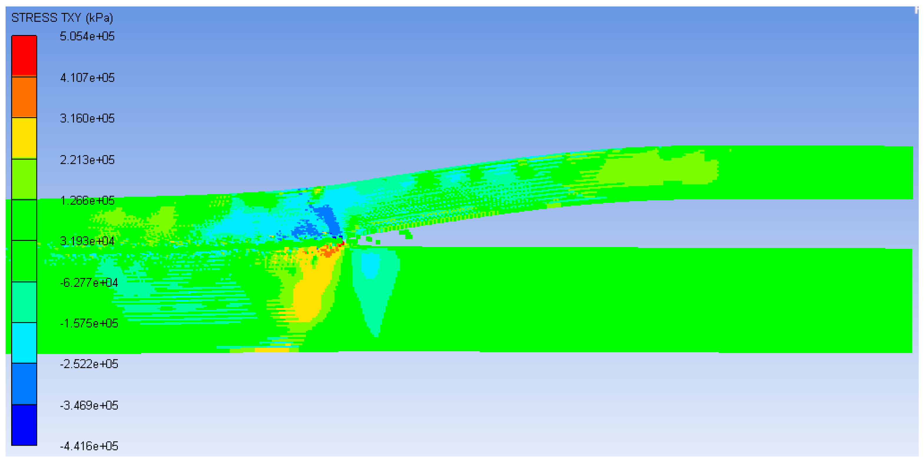
The shear stress can be regarded as an index for detecting the emergence of good bonding [5,14,19]. The distribution of shear stress is presented in Figure 9. It is indicated that the shear stress direction on the two plates is opposite, i.e., being negative in the flyer plate, while positive in the base plate, and the distributions of shear stresses in both plates are not uniform. Mousavi and Al-Hassani [5] concluded that the bonding could not be achieved if the shear stresses around the collision area were of the same sign. Moreover, the absolute value of shear stress in the base plate is larger than in the flyer plate, which may result in more material loss of the base plate in comparison with that of flyer plate, confirming the phenomenon that jetting mostly derives from the base plate.
3.5. Interface Morphology of Composite Plate
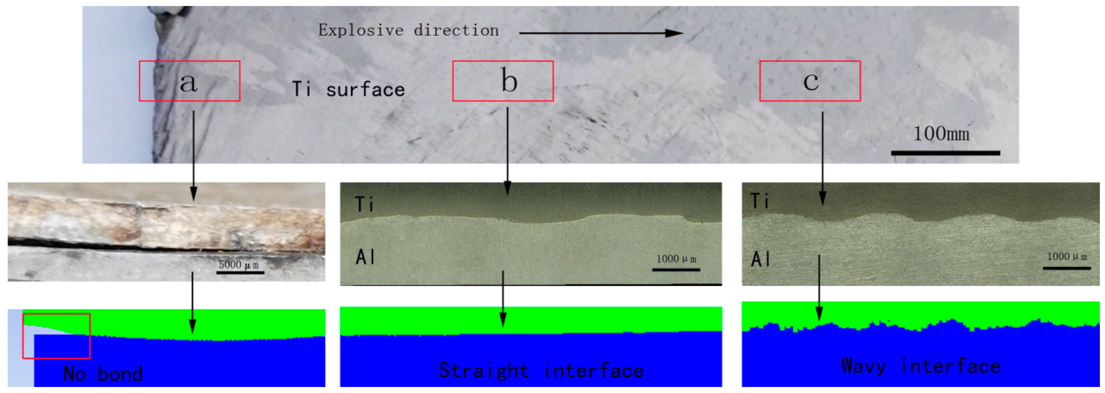
To validate the numerical model, an explosive welding experiment was conducted. Experimental parameters of explosive welding were chosen based on the above numerical simulation. As shown in Figure 10, the titanium surface showed no macroscopic cracks except for the small zones near the detonation position. In order to discuss the interface morphology of the composite plate, three cross-sections of the specimen were extracted along the detonation direction. In Figure 10, position “a” is the detonation position where no bonding was observed, this is the explosive welding boundary effect. As discussed before, the pressure at the detonating point was too small to achieve the bonding. “b” and “c” were the cross-sections of the composite at two selected positions away from the detonation point. It can be observed that the welding quality was sound, and no cracks or pores appeared in the simulation and experiment. According to the Figure 10, the Ti and Al plates were bonded successfully through explosive welding. In contrast, the bonding interface close to the detonation point showed a linear morphology (position “b”), while the bonding interface away from the detonation point achieved a wavy morphology (position “c”). It is generally accepted that the occurrence of jetting at the collision interface is one of the necessary conditions for the formation of a wavy interface [1,4,15]. According to Figure 3b,c, the jet did not exist at the initial stage of the explosion, with the collision point moving forward, periodic wave structures were formed as the jetting appeared.
Comparison of the experiment and numerical simulation, both of the results about the interface morphology are coherent, which further validated the accuracy of the explosive welding numerical model.
4. Conclusions
In this study, basing on the ANSYS/AUTODYN software package, a 2D numerical model that is more physically realistic was established for the simulation study of the complete process of Ti/Al explosive welding. The simulation results show some conclusions below:
- The typical physics of explosive welding process can be reproduced using the present model, such as the expansion of the explosives, flyer plate bending, oblique impact of metal plates, and jetting, which are not possible to capture in experiments. The jet phenomenon which originated mostly from the aluminum plate was observed in the collision region.
- After detonation, the flyer plate is accelerated gradually and collides with the base plate. The jet velocity is the highest and can reach 7402 m/s near the collision zone.
- The pressure at the detonation point is too small to achieve bonding between the two plates, which is the reason for the boundary effect of explosive welding. The pressure could reach an order of magnitude of 107 kPa when the detonation energy tends to be stable.
- There emerges an obvious narrow region of plastic strain near the collision zone. The shear stress between the two plates has opposite signs.
- The interface morphology changes from straight to wave along the propagation of the detonation wave in the simulation, which is consistent with the actual interface morphology of the Ti/Al bimetal composite acquired in the experiment.
Acknowledgments
This work is supported by the Graduate Education Innovation Project of Shanxi Province (No. 2017BY120), the Project of Joint Training Base for Graduate Students in Shanxi Province (No. 2017JD30), the National Key Technology Research and Development Program (No. 2012CB722800), the National Natural Science Foundation of China (No. 51275332), the Natural Science Foundation of Shanxi Province (No. 201601D011036), and the Natural Science Youth Foundation of Shanxi Province (No. 2015021130).
Author Contributions
Zhisheng Wu conceived and designed the research project; Yan Li performed the numerical simulation and wrote the paper; Cuirong Liu analyzed the data and contributed to the revision of the paper; Haibo Yu revised the language and designed the article structure; and Fei Zhao designed and performed the explosion welding experiment.
Conflicts of Interest
The authors declare no conflict of interest.
References
- Findik, F. Recent developments in explosive welding. Mater. Des. 2011, 32, 1081–1093. [Google Scholar] [CrossRef]
- Loureiro, A.; Mendes, R.; Ribeiro, J.B.; Leal, R.M.; Galvao, I. Effect of explosive mixture on quality of explosive welds of copper to aluminium. Mater. Des. 2016, 95, 256–267. [Google Scholar] [CrossRef]
- Fronczek, D.M.; Wojewoda-Budka, J.; Chulist, R.; Sypien, A.; Korneva, A.; Szulc, Z.; Schell, N.; Zieba, P. Structural properties of Ti/Al clads manufactured by explosive welding and annealing. Mater. Des. 2016, 91, 80–89. [Google Scholar] [CrossRef]
- Li, Y.; Wu, Z. Microstructural characteristics and mechanical properties of 2205/AZ31B laminates fabricated by explosive welding. Metals 2017, 7, 125. [Google Scholar] [CrossRef]
- Mousavi, A.; Al-Hassani, S.T.S. Numerical and experimental studies of the mechanism of the wavy interface formations in explosive/impact welding. J. Mech. Phys. Solids 2005, 53, 2501–2528. [Google Scholar]
- Nassiri, A.; Kinsey, B. Numerical studies on high-velocity impact welding: Smoothed particle hydrodynamics (SPH) and arbitrary Lagrangian-Eulerian (ALE). J. Manuf. Process. 2016, 24, 376–381. [Google Scholar] [CrossRef]
- Wang, X.; Zheng, Y.; Liu, H.; Shen, Z.; Hu, Y.; Gao, Y.; Guo, C. Numerical study of the mechanism of explosive/impact welding using smoothed particle hydrodynamics method. Mater. Des. 2012, 35, 210–219. [Google Scholar] [CrossRef]
- Nassiri, A.; Chini, G.; Vivek, A.; Daehn, G.; Kinsey, B. Arbitrary Lagrangian-Eulerian finite element simulation and experimental investigation of wavy interfacial morphology during high velocity impact welding. Mater. Des. 2015, 88, 345–358. [Google Scholar] [CrossRef]
- Aizawa, Y.; Nishiwaki, J.; Harada, Y.; Muraishi, S.; Kumai, S. Experimental and numerical analysis of the formation behavior of intermediate layers at explosive welded Al/Fe joint interfaces. J. Manuf. Process. 2016, 24, 100–106. [Google Scholar] [CrossRef]
- Abe, A. Numerical study of the mechanism of wavy interface generation in explosive welding. JSME Int. J. Ser. B Fluid. Therm. Eng. 1997, 40, 395–401. [Google Scholar] [CrossRef]
- Yuan, X.; Wang, W.; Cao, X.; Zhang, T.; Xie, R.; Liu, R. Numerical study on the interfacial behavior of Mg/Al plate in explosive/impact welding. Sci. Eng. Compos. Mater. 2017, 24. [Google Scholar] [CrossRef]
- Grignon, F.; Benson, D.; Vecchio, K.S.; Meyers, M.A. Explosive welding of aluminum to aluminum: Analysis, computations and experiments. Int. J. Impact Eng. 2004, 30, 1333–1351. [Google Scholar] [CrossRef]
- Carrino, L.; Paradiso, V.; Franchitti, S.; Squillace, A.; Russo, S. Superplastic forming/diffusion bonding of a titanium alloy for the realization of an aircraft structural component in multi-sheets configuration. Key Eng. Mater. 2012, 504–506, 717–722. [Google Scholar] [CrossRef]
- Li, X.J.; Mo, F.; Wang, X.H.; Liu, X.W. Numerical study on mechanism of explosive welding. Sci. Technol. Weld. Join. 2012, 17, 36–41. [Google Scholar] [CrossRef]
- Fan, M.; Domblesky, J.; Jin, K.; Qin, L.; Cui, S.; Guo, X.; Kim, N.; Tao, J. Effect of original layer thicknesses on the interface bonding and mechanical properties of Ti/Al laminate composites. Mater. Des. 2016, 99, 535–542. [Google Scholar] [CrossRef]
- Xia, H.B.; Wang, S.G.; Ben, H.F. Microstructure and mechanical properties of Ti/Al explosive cladding. Mater. Des. 2014, 56, 1014–1019. [Google Scholar] [CrossRef]
- Bataev, I.A.; Bataev, A.A.; Mali, V.I.; Pavliukova, D.V. Structural and mechanical properties of metallic-intermetallic laminate composites produced by explosive welding and annealing. Mater. Des. 2012, 35, 225–234. [Google Scholar] [CrossRef]
- Lee, E.; Finger, M.; Collins, W. JWL Equation of State Coefficients for High Explosives; Lawrance Livermore National Laboratory: Livermore, CA, USA, 1973. [Google Scholar]
- Liu, R.; Wang, W.; Zhang, T.; Yuan, X. Numerical study of Ti/Al/Mg three-layer plates on the interface behavior in explosive welding. Sci. Eng. Compos. Mater. 2016, 24. [Google Scholar] [CrossRef]
- AUTODYN, version 6.1; Century Dynamics Incorporated: Concord, CA, USA, 2007.
- Corbett, B.M. Numerical simulations of target hole diameters for hypervelocity impacts into elevated and room temperature bumpers. Int. J. Impact Eng. 2006, 33, 431–440. [Google Scholar] [CrossRef]
- Steinberg, D.J.; Cochran, S.G.; Guinan, M.W. A constitutive model for metals applicable at high-strain rate. J. Appl. Phys. 1980, 51, 1498–1504. [Google Scholar] [CrossRef]
- Zhou, C.E.; Liu, G.R.; Lou, K.Y. Three-dimensional penetration simulation using smoothed particle hydrodynamics. Int. J. Comput. Method 2007, 4, 671–691. [Google Scholar] [CrossRef]
- Liu, M.B.; Zhang, Z.L.; Feng, D.L. A density-adaptive SPH method with kernel gradient correction for modeling explosive welding. Comput. Mech. 2017, 1–17. [Google Scholar] [CrossRef]
- Nassiri, A. Investigation of Wavy Interfacial Morphology in Magnetic Pulsed Welding: Mathematical Modeling, Numerical Simulations and Experimental Tests. Ph.D. Thesis, University of New Hampshire, Durham, NH, USA, July 2015. [Google Scholar]
- Mousavi, A.; Burley, S.J.; Al-Hassani, S.T.S. Simulation of explosive welding using the Williamsburg equation of state to model low detonation velocity explosives. Int. J. Impact Eng. 2005, 31, 719–734. [Google Scholar] [CrossRef]
- Hayhurst, C.J.; Clegg, R.A. Cylindrically symmetric SPH simulations of hypervelocity impacts on thin plates. Int. J. Impact Eng. 1997, 20, 337–348. [Google Scholar] [CrossRef]
- Yan, Y.B.; Zhang, Z.W.; Shen, W.; Wang, J.H.; Zhang, L.K.; Chin, B.A. Microstructure and properties of magnesium AZ31B–aluminum 7075 explosively welded composite plate. Mater. Sci. Eng. A 2010, 527, 2241–2245. [Google Scholar] [CrossRef]
- Kahraman, N.; Gulenc, B.; Findik, F. Corrosion and mechanical-microstructural aspects of dissimilar joints of Ti-6Al-4V and Al plates. Int. J. Impact Eng. 2007, 34, 1423–1432. [Google Scholar] [CrossRef]
- Sui, G.F.; Li, J.S.; Sun, F.; Ma, B.; Li, H. 3D finite element simulation of explosive welding of three-layer plates. Sci. China Phys. Mech. Astron. 2011, 54, 890–896. [Google Scholar] [CrossRef]
- Akbari-Mousavi, S.A.A.; Barrett, L.M.; Al-Hassani, S.T.S. Explosive welding of metal plates. J. Mater. Process. Technol. 2008, 202, 224–239. [Google Scholar] [CrossRef]
- Mastanaiah, P.; Reddy, G.M.; Prasad, K.S.; Murthy, C.V.S. An investigation on microstructures and mechanical properties of explosive cladded C103 niobium alloy over C263 niobium alloy. J. Mater. Process. Technol. 2014, 214, 2316–2324. [Google Scholar] [CrossRef]
- Zheng, Y. Explosive Welding and Metallic Composite and Their Engineering Application; Central South University Press: Changsha, China, 2002. [Google Scholar]
Figure 1.
Schematic of the HVIW (high-velocity impact welding) model.

Figure 2.
The model of Ti/Al explosive welding in the simulation (ANFO: Ammonium-nitrate/fuel-oil).
Figure 3.
The explosive welding process in the simulation: (a) Before explosion; (b) initial explosion; (c) jet appearance; (d) welding completed.
Figure 3.
The explosive welding process in the simulation: (a) Before explosion; (b) initial explosion; (c) jet appearance; (d) welding completed.

Figure 4.
The contour of the velocity distribution.

Figure 5.
The Y-direction velocity-time curves of the special points.

Figure 6.
The contour of the pressure distribution.

Figure 7.
The pressure-time curves of special points.

Figure 8.
The contour of effective plastic strain distribution.
Figure 9.
The contour of shear stress distribution.

Figure 10.
The interface of the Ti/Al composite plate fabricated by explosive welding.


Table 1.
Geometry parameters of two-layer plates, explosive, and anvil used in the model (ANFO: Ammonium-nitrate/fuel-oil).
Table 1.
Geometry parameters of two-layer plates, explosive, and anvil used in the model (ANFO: Ammonium-nitrate/fuel-oil).
| Material | Geometry (Length × Height) (mm) |
|---|---|
| Explosive—ANFO | 20 × 5 |
| Flyer plate—TA1 | 20 × 2 |
| Base plate—Al 1060 | 20 × 3 |
| Anvil—Steel 1006 | 20 × 8 |
Table 2.
EOS (equation of state) parameters of the ANFO explosive [20].
Table 2.
EOS (equation of state) parameters of the ANFO explosive [20].
| V/(m·s−1) | ρ/(kg·m−3) | E0/GJ | A/GJ | B/GJ | R1 | R2 | ω |
|---|---|---|---|---|---|---|---|
| 2500 | 790 | 2.48 | 491 | 0.89 | 3.9 | 1.18 | 0.33 |
Table 3.
Parameters using EOS and constitutive models.
| Materials | ρ/(kg·m−3) | C | m | n | Tmelt/°C | Rτ/GPa | Y0/GPa |
|---|---|---|---|---|---|---|---|
| TA1 | 4520 | 0.03 | 0.8 | 0.32 | 1660 | 55 | 0.16 |
| Al 1060 | 2770 | 0.01 | 1 | 0.41 | 660 | 27 | 0.04 |
| Steel 1006 | 7896 | 0.22 | 1 | 0.36 | 1811 | 81.8 | 0.35 |
© 2017 by the authors. Licensee MDPI, Basel, Switzerland. This article is an open access article distributed under the terms and conditions of the Creative Commons Attribution (CC BY) license (http://creativecommons.org/licenses/by/4.0/).
Share and Cite
MDPI and ACS Style
Li, Y.; Liu, C.; Yu, H.; Zhao, F.; Wu, Z. Numerical Simulation of Ti/Al Bimetal Composite Fabricated by Explosive Welding. Metals 2017, 7, 407. https://doi.org/10.3390/met7100407
AMA Style
Li Y, Liu C, Yu H, Zhao F, Wu Z. Numerical Simulation of Ti/Al Bimetal Composite Fabricated by Explosive Welding. Metals. 2017; 7(10):407. https://doi.org/10.3390/met7100407
Chicago/Turabian StyleLi, Yan, Cuirong Liu, Haibo Yu, Fei Zhao, and Zhisheng Wu. 2017. "Numerical Simulation of Ti/Al Bimetal Composite Fabricated by Explosive Welding" Metals 7, no. 10: 407. https://doi.org/10.3390/met7100407
Note that from the first issue of 2016, this journal uses article numbers instead of page numbers. See further details here.